EP4495950A1 - Cooling device and cooling method for small modular reactor - Google Patents
Cooling device and cooling method for small modular reactor Download PDFInfo
- Publication number
- EP4495950A1 EP4495950A1 EP23771033.0A EP23771033A EP4495950A1 EP 4495950 A1 EP4495950 A1 EP 4495950A1 EP 23771033 A EP23771033 A EP 23771033A EP 4495950 A1 EP4495950 A1 EP 4495950A1
- Authority
- EP
- European Patent Office
- Prior art keywords
- coolant
- melted material
- small modular
- reactor vessel
- storage unit
- Prior art date
- Legal status (The legal status is an assumption and is not a legal conclusion. Google has not performed a legal analysis and makes no representation as to the accuracy of the status listed.)
- Pending
Links
Images


Classifications
-
- G—PHYSICS
- G21—NUCLEAR PHYSICS; NUCLEAR ENGINEERING
- G21C—NUCLEAR REACTORS
- G21C9/00—Emergency protection arrangements structurally associated with the reactor, e.g. safety valves provided with pressure equalisation devices
- G21C9/016—Core catchers
-
- G—PHYSICS
- G21—NUCLEAR PHYSICS; NUCLEAR ENGINEERING
- G21C—NUCLEAR REACTORS
- G21C1/00—Reactor types
- G21C1/32—Integral reactors, i.e. reactors wherein parts functionally associated with the reactor but not essential to the reaction, e.g. heat exchangers, are disposed inside the enclosure with the core
-
- G—PHYSICS
- G21—NUCLEAR PHYSICS; NUCLEAR ENGINEERING
- G21C—NUCLEAR REACTORS
- G21C15/00—Cooling arrangements within the pressure vessel containing the core; Selection of specific coolants
- G21C15/18—Emergency cooling arrangements; Removing shut-down heat
-
- G—PHYSICS
- G21—NUCLEAR PHYSICS; NUCLEAR ENGINEERING
- G21C—NUCLEAR REACTORS
- G21C15/00—Cooling arrangements within the pressure vessel containing the core; Selection of specific coolants
- G21C15/02—Arrangements or disposition of passages in which heat is transferred to the coolant; Coolant flow control devices
- G21C15/12—Arrangements or disposition of passages in which heat is transferred to the coolant; Coolant flow control devices from pressure vessel; from containment vessel
-
- Y—GENERAL TAGGING OF NEW TECHNOLOGICAL DEVELOPMENTS; GENERAL TAGGING OF CROSS-SECTIONAL TECHNOLOGIES SPANNING OVER SEVERAL SECTIONS OF THE IPC; TECHNICAL SUBJECTS COVERED BY FORMER USPC CROSS-REFERENCE ART COLLECTIONS [XRACs] AND DIGESTS
- Y02—TECHNOLOGIES OR APPLICATIONS FOR MITIGATION OR ADAPTATION AGAINST CLIMATE CHANGE
- Y02E—REDUCTION OF GREENHOUSE GAS [GHG] EMISSIONS, RELATED TO ENERGY GENERATION, TRANSMISSION OR DISTRIBUTION
- Y02E30/00—Energy generation of nuclear origin
- Y02E30/30—Nuclear fission reactors
Definitions
- the present disclosure relates to a cooling device and cooling method for small modular reactor.
- a representative facility is a core catcher, which collects and retains the core melted material and cools the core melted material by supplying a coolant in the lower cavity of the reactor building.
- the core catcher which was developed by installing a cooling flow path at the bottom of the conventional core melted material collection vessel to cool the core melted material, includes AREVA EPR and GE ESBWR application technologies.
- the AREVA EPR core catcher consists of a pre-catcher that collects the core melted material, a core melted material transfer channel, and a space for spreading and cooling the core melted material.
- the cooling flow path of the AREVA EPR is horizontal and has the form of a square cooling channel with the cooling flow path being separated by a structure that supports a vessel for retaining and spreading the core melted material.
- the GE ESBWR core catcher has a structure in which a funnel-shaped vessel that collects, spreads, and cools the core melted material is installed directly below the reactor. All of these existing core catchers are installed outside the reactor. However, in the case of SMR that does not have a containment building or is designed to be in close contact with the reactor vessel, such a core catcher may not be installed.
- aspects of the present disclosure are to enable in-vessel retention of an internal core melted material in the event of a serious accident in SMR.
- aspects of the present disclosure are also to ensure that the core melted material is caught on a coolant tank at a bottom of a reactor in the event of a serious accident.
- aspects of the present disclosure are also to ensure time for a stop cooling of a system to be smoothly performed by other passive or active safety equipment.
- a small modular reactor cooling method including: circulating a coolant inside a reactor vessel along a flow path structure; charging the coolant into a coolant storage unit inside the reactor vessel; generating a core melted material in the reactor vessel in the event of a serious accident; and preventing the core melted material from leaking out to the outside by cooling the core melted material through the coolant charged inside the coolant storage unit.
- the coolant storage unit may include a receptor positioned at a lower portion of an inner circumferential surface of the reactor vessel, and an injection body provided in the receptor and into which the coolant is injected according to the circulating flow.
- the injection body may allow the coolant to flow from the outside to the inside and prevent the coolant from leaking from the inside to the outside.
- the injection body may prevent the leakage through a unidirectional opening and closing operation.
- the injection body may perform the opening and closing operation using a check valve method.
- the receptor may be formed so that a lower portion corresponds to a lower inner circumferential surface of the reactor vessel and an upper portion is rounded downward.
- the injection body may be provided on at least a portion of an upper peripheral portion of the receptor, based on the upper portion that is rounded downward, and be injected with the coolant according to the circulating flow.
- a small modular reactor cooling device including: a reactor vessel in which a coolant circulates along a flow path structure; and a coolant storage unit provided inside the reactor vessel and charged with the coolant inside based on the circulating flow, wherein the coolant storage unit is in contact with a core melted material through the coolant charged therein when the core melted material is generated in the reactor vessel in the event of a serious accident and performs a cooling treatment on the core melted material to prevent the core melted material from leaking out to the outside.
- the present disclosure may perform in vessel retention of the internal core melted material in the event of a serious accident in SMR.
- the present disclosure may ensure that the core melted material is caught on the coolant tank at the bottom of the reactor in the event of a serious accident.
- the present disclosure may ensure time for the stop cooling of the system to be smoothly performed by other passive or active safety equipment.
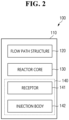
- a small modular reactor cooling device 100 includes a reactor vessel 110, a flow path structure 120, a reactor core 130, and a coolant storage unit 140.
- the coolant storage unit 140 includes a receptor 141 and an injection body 142.
- the reactor vessel 110 of the small modular reactor cooling device 100 is provided with the flow path structure 120 therein.
- the flow path structure 120 is intended to allow a coolant W1 inside the reactor vessel 110 to circulate.
- the flow path structure 120 corresponds to a predetermined structure or area for circulation of the coolant W1.
- the coolant storage unit 140 is provided inside the reactor vessel 110.
- the coolant storage unit 140 has the coolant W1 at least partially charged therein based on the circulating flow of the coolant W1.
- the coolant storage unit 140 comes into contact with the core melted material through the coolant W1 charged therein.
- the coolant storage unit 140 performs cooling treatment on the core melted material based on the contact with the core melted material. At the same time, the coolant storage unit 140 prevents the core melted material from leaking out to the outside.
- the coolant storage unit 140 serves to collect the core melted material and prevent direct heat transfer with a lower outer wall of the reactor vessel 110.
- the receptor 141 of the coolant storage unit 140 is positioned at a lower portion of an inner circumferential surface of the reactor vessel 110.
- the injection body 142 of the coolant storage unit 140 is provided in the receptor 141.
- the coolant W1 is injected into the injection body 142 according to the circulating flow of the coolant.
- the injection body 142 allows the coolant W1 to flow from the outside to the inside.
- the injection body 142 prevents the coolant W1 from leaking from the inside to the outside.
- the injection body 142 prevents the leakage through a unidirectional opening and closing operation.
- the injection body 142 allows the opening and closing operation to be performed using a check valve method, etc.
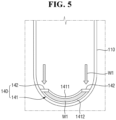
- the receptor 141 is formed so that a lower portion 1412 thereof corresponds to a lower inner circumferential surface of the reactor vessel 110.
- the receptor 141 is formed so that an upper portion 1411 thereof is rounded downward.
- the injection body 142 is provided on at least a portion of an upper peripheral portion of the receptor 141, based on the upper portion 1411 that is rounded downward.
- the coolant W1 is injected into the injection body 142 according to the circulating flow of the coolant W1.
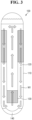
- the receptor 141 is provided so that a portion of an outer circumferential surface thereof has a double structure, as illustrated in FIG. 3 . Furthermore, the receptor 141 may also be provided so that the outer circumferential surfaces of the upper, lower, left, and right sides have an overall dual structure, as illustrated in FIG. 4 .
- a coolant W1 circulates along a flow path structure 120 inside a reactor vessel 110.
- the circulating coolant W1 is charged into a coolant storage unit 140 inside the reactor vessel 110.
- the coolant storage unit 140 cools the core melted material through the coolant W1 charged therein.
- the coolant storage unit 140 prevents the core melted material from leaking out to the outside.
- a receptor 141 of the coolant storage unit 140 is positioned at a lower portion of an inner circumferential surface of the reactor vessel 110.
- An injection body 142 of the coolant storage unit 140 is provided in the receptor 141, and the coolant W1 is injected into the injection body 142 according to the circulating flow.
- the injection body 142 allows the coolant W1 to flow from the outside to the inside, and prevents the coolant W1 from leaking out to the outside.
- the injection body 142 prevents the leakage through a unidirectional opening and closing operation.
- the injection body 142 performs the opening and closing operation using a check valve method.
- the receptor 141 is formed so that a lower portion 1412 thereof corresponds to a lower inner circumferential surface of the reactor vessel 110 and an upper portion 1411 thereof is rounded downward.
- the injection body 142 is provided on at least a portion of an upper peripheral portion of the receptor 141, based on the upper portion 1411 that is rounded downward.
- the coolant W1 is injected into the injection body 142 according to the circulating flow.
Landscapes
- Physics & Mathematics (AREA)
- Engineering & Computer Science (AREA)
- Plasma & Fusion (AREA)
- General Engineering & Computer Science (AREA)
- High Energy & Nuclear Physics (AREA)
- Chemical & Material Sciences (AREA)
- Chemical Kinetics & Catalysis (AREA)
- Structure Of Emergency Protection For Nuclear Reactors (AREA)
Abstract
Description
- The present disclosure relates to a cooling device and cooling method for small modular reactor.
- In the nuclear power plant related technology field, a small modular reactor (SMR) is being developed with a focus on improving safety. However, despite the existence of various safety stop systems related to safety, there have been no specific cases in which measures to prevent external leakage of a melted core material within an SMR reactor have been developed for serious accidents where the probability of occurrence is very low.
- To cope with a loss of integrity of a reactor building in the event of a major accident at a general large commercial nuclear power plant, there are several countermeasures to retain and cool the core melted material to prevent direct reaction between the core melted material and a lower cavity floor concrete of the reactor building. For example, a representative facility is a core catcher, which collects and retains the core melted material and cools the core melted material by supplying a coolant in the lower cavity of the reactor building.
- The core catcher, which was developed by installing a cooling flow path at the bottom of the conventional core melted material collection vessel to cool the core melted material, includes AREVA EPR and GE ESBWR application technologies. The AREVA EPR core catcher consists of a pre-catcher that collects the core melted material, a core melted material transfer channel, and a space for spreading and cooling the core melted material. The cooling flow path of the AREVA EPR is horizontal and has the form of a square cooling channel with the cooling flow path being separated by a structure that supports a vessel for retaining and spreading the core melted material.
- The GE ESBWR core catcher has a structure in which a funnel-shaped vessel that collects, spreads, and cools the core melted material is installed directly below the reactor. All of these existing core catchers are installed outside the reactor. However, in the case of SMR that does not have a containment building or is designed to be in close contact with the reactor vessel, such a core catcher may not be installed.
- Aspects of the present disclosure are to enable in-vessel retention of an internal core melted material in the event of a serious accident in SMR.
- Aspects of the present disclosure are also to ensure that the core melted material is caught on a coolant tank at a bottom of a reactor in the event of a serious accident.
- Aspects of the present disclosure are also to ensure time for a stop cooling of a system to be smoothly performed by other passive or active safety equipment.
- Aspects of the present disclosure are not limited to the aspects mentioned above, and other aspects not mentioned will be clearly understood by those skilled in the art from the following description.
- According to an aspect of the present disclosure, there is provided a small modular reactor cooling method including: circulating a coolant inside a reactor vessel along a flow path structure; charging the coolant into a coolant storage unit inside the reactor vessel; generating a core melted material in the reactor vessel in the event of a serious accident; and preventing the core melted material from leaking out to the outside by cooling the core melted material through the coolant charged inside the coolant storage unit.
- The coolant storage unit may include a receptor positioned at a lower portion of an inner circumferential surface of the reactor vessel, and an injection body provided in the receptor and into which the coolant is injected according to the circulating flow.
- The injection body may allow the coolant to flow from the outside to the inside and prevent the coolant from leaking from the inside to the outside.
- The injection body may prevent the leakage through a unidirectional opening and closing operation.
- The injection body may perform the opening and closing operation using a check valve method.
- The receptor may be formed so that a lower portion corresponds to a lower inner circumferential surface of the reactor vessel and an upper portion is rounded downward.
- The injection body may be provided on at least a portion of an upper peripheral portion of the receptor, based on the upper portion that is rounded downward, and be injected with the coolant according to the circulating flow.
- According to another aspect of the present disclosure, there is provided a small modular reactor cooling device including: a reactor vessel in which a coolant circulates along a flow path structure; and a coolant storage unit provided inside the reactor vessel and charged with the coolant inside based on the circulating flow, wherein the coolant storage unit is in contact with a core melted material through the coolant charged therein when the core melted material is generated in the reactor vessel in the event of a serious accident and performs a cooling treatment on the core melted material to prevent the core melted material from leaking out to the outside.
- According to the small modular reactor cooling device and cooling method of the present disclosure as described above, there are one or more of the following effects.
- The present disclosure may perform in vessel retention of the internal core melted material in the event of a serious accident in SMR.
- Furthermore, the present disclosure may ensure that the core melted material is caught on the coolant tank at the bottom of the reactor in the event of a serious accident.
- Furthermore, the present disclosure may ensure time for the stop cooling of the system to be smoothly performed by other passive or active safety equipment.
-
-
FIG. 1 is a block diagram illustrating a configuration of a small modular reactor cooling device according to an embodiment of the present disclosure; -
FIG. 2 is a block diagram illustrating the configuration according toFIG. 1 in detail; -
FIG. 3 is a configuration diagram illustrating the configuration according toFIG. 1 ; -
FIG. 4 is a schematic diagram illustrating an embodiment of the configuration according toFIG. 1 ; -
FIG. 5 is a schematic diagram illustrating another embodiment of the configuration according toFIG. 1 ; and -
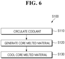
FIG. 6 is a flowchart sequentially illustrating a small modular reactor cooling method according to an embodiment of the present disclosure. - Hereinafter, embodiments of the present disclosure will be described in detail with reference to the accompanying drawings. Hereinafter, preferred embodiments of the present disclosure will be described in detail with reference to the attached drawings. Advantages and features of the present disclosure, and a method for achieving the advantages and features will become apparent with reference to the embodiments described below in detail in conjunction with the accompanying drawings. However, the present disclosure is not limited to the embodiments disclosed below, but may be implemented in a variety of different forms, these embodiments will be provided only in order to make the present disclosure complete and allow those skilled in the art to completely recognize the scope of the present disclosure, and the present disclosure is only defined by the scope of the claims. The same reference numbers indicate the same components throughout the specification.
- Referring to
FIG. 1 , a small modularreactor cooling device 100 according to an embodiment of the present disclosure includes areactor vessel 110, aflow path structure 120, areactor core 130, and acoolant storage unit 140. Referring toFIG. 2 , thecoolant storage unit 140 includes areceptor 141 and aninjection body 142. - Referring to
FIGS. 2 to 4 , thereactor vessel 110 of the small modularreactor cooling device 100 is provided with theflow path structure 120 therein. Theflow path structure 120 is intended to allow a coolant W1 inside thereactor vessel 110 to circulate. - The
flow path structure 120 corresponds to a predetermined structure or area for circulation of the coolant W1. Thecoolant storage unit 140 is provided inside thereactor vessel 110. - Referring to
FIG. 4 , thecoolant storage unit 140 has the coolant W1 at least partially charged therein based on the circulating flow of the coolant W1. When a core melted material is generated in thereactor vessel 110 in the event of a serious accident, thecoolant storage unit 140 comes into contact with the core melted material through the coolant W1 charged therein. - The
coolant storage unit 140 performs cooling treatment on the core melted material based on the contact with the core melted material. At the same time, thecoolant storage unit 140 prevents the core melted material from leaking out to the outside. - Here, the
coolant storage unit 140 serves to collect the core melted material and prevent direct heat transfer with a lower outer wall of thereactor vessel 110. Thereceptor 141 of thecoolant storage unit 140 is positioned at a lower portion of an inner circumferential surface of thereactor vessel 110. - The
injection body 142 of thecoolant storage unit 140 is provided in thereceptor 141. The coolant W1 is injected into theinjection body 142 according to the circulating flow of the coolant. - Furthermore, the
injection body 142 allows the coolant W1 to flow from the outside to the inside. Theinjection body 142 prevents the coolant W1 from leaking from the inside to the outside. - The
injection body 142 prevents the leakage through a unidirectional opening and closing operation. Theinjection body 142 allows the opening and closing operation to be performed using a check valve method, etc. - The
receptor 141 is formed so that alower portion 1412 thereof corresponds to a lower inner circumferential surface of thereactor vessel 110. Thereceptor 141 is formed so that anupper portion 1411 thereof is rounded downward. - The
injection body 142 is provided on at least a portion of an upper peripheral portion of thereceptor 141, based on theupper portion 1411 that is rounded downward. The coolant W1 is injected into theinjection body 142 according to the circulating flow of the coolant W1. - Here, the
receptor 141 is provided so that a portion of an outer circumferential surface thereof has a double structure, as illustrated inFIG. 3 . Furthermore, thereceptor 141 may also be provided so that the outer circumferential surfaces of the upper, lower, left, and right sides have an overall dual structure, as illustrated inFIG. 4 . - Referring to
FIG. 6 , in a small modular reactor cooling method (S100) according to an embodiment of the present disclosure, a coolant W1 circulates along aflow path structure 120 inside areactor vessel 110. The circulating coolant W1 is charged into acoolant storage unit 140 inside thereactor vessel 110. - Here, when a serious accident occurs, a core melted material is generated in the
reactor vessel 110. Thecoolant storage unit 140 cools the core melted material through the coolant W1 charged therein. - Furthermore, the
coolant storage unit 140 prevents the core melted material from leaking out to the outside. Areceptor 141 of thecoolant storage unit 140 is positioned at a lower portion of an inner circumferential surface of thereactor vessel 110. - An
injection body 142 of thecoolant storage unit 140 is provided in thereceptor 141, and the coolant W1 is injected into theinjection body 142 according to the circulating flow. Theinjection body 142 allows the coolant W1 to flow from the outside to the inside, and prevents the coolant W1 from leaking out to the outside. - The
injection body 142 prevents the leakage through a unidirectional opening and closing operation. Theinjection body 142 performs the opening and closing operation using a check valve method. Thereceptor 141 is formed so that alower portion 1412 thereof corresponds to a lower inner circumferential surface of thereactor vessel 110 and anupper portion 1411 thereof is rounded downward. - Here, the
injection body 142 is provided on at least a portion of an upper peripheral portion of thereceptor 141, based on theupper portion 1411 that is rounded downward. The coolant W1 is injected into theinjection body 142 according to the circulating flow. - Although the embodiments of the present disclosure have been described with reference to the accompanying drawings, those of ordinary skill in the art to which the present disclosure pertains will understand that the present disclosure may be embodied in other specific forms without changing the technical spirit or essential features thereof. Therefore, it should be understood that the exemplary embodiments described above are illustrative in all aspects and not restrictive.
Claims (9)
- A small modular reactor cooling method comprising:circulating a coolant inside a reactor vessel along a flow path structure;charging the coolant into a coolant storage unit inside the reactor vessel;generating a core melted material in the reactor vessel in the event of a serious accident; andpreventing the core melted material from leaking out to the outside by cooling the core melted material through the coolant charged inside the coolant storage unit.
- The small modular reactor cooling method of claim 1, wherein the coolant storage unit includes:a receptor positioned at a lower portion of an inner circumferential surface of the reactor vessel, andan injection body provided in the receptor and into which the coolant is injected according to the circulating flow.
- The small modular reactor cooling method of claim 2, wherein the injection body allows the coolant to flow from the outside to the inside and prevents the coolant from leaking from the inside to the outside.
- The small modular reactor cooling method of claim 3, wherein the injection body prevents the leakage through a unidirectional opening and closing operation.
- The small modular reactor cooling method of claim 4, wherein the injection body performs the opening and closing operation using a check valve method.
- The small modular reactor cooling method of claim 3, wherein the receptor is formed so that a lower portion corresponds to a lower inner circumferential surface of the reactor vessel and an upper portion is rounded downward.
- A small modular reactor cooling device comprising:a reactor vessel in which a coolant circulates along a flow path structure; anda coolant storage unit provided inside the reactor vessel and charged with the coolant inside based on the circulating flow,wherein the coolant storage unit is in contact with a core melted material through the coolant charged therein when the core melted material is generated in the reactor vessel in the event of a serious accident and performs a cooling treatment on the core melted material to prevent the core melted material from leaking out to the outside.
- The small modular reactor cooling device of claim 7, wherein the coolant storage unit includes:a receptor positioned at a lower portion of an inner circumferential surface of the reactor vessel, andan injection body provided in the receptor and into which the coolant is injected according to the circulating flow.
- The small modular reactor cooling device of claim 8, wherein the injection body allows the coolant to flow from the outside to the inside and prevents the coolant from leaking from the inside to the outside.
Applications Claiming Priority (2)
| Application Number | Priority Date | Filing Date | Title |
|---|---|---|---|
| KR1020220031448A KR102649036B1 (en) | 2022-03-14 | 2022-03-14 | Small modular reactor cooling apparatus and cooling method |
| PCT/KR2023/003289 WO2023177154A1 (en) | 2022-03-14 | 2023-03-10 | Cooling device and cooling method for small modular reactor |
Publications (2)
| Publication Number | Publication Date |
|---|---|
| EP4495950A1 true EP4495950A1 (en) | 2025-01-22 |
| EP4495950A4 EP4495950A4 (en) | 2026-02-25 |
Family
ID=88023949
Family Applications (1)
| Application Number | Title | Priority Date | Filing Date |
|---|---|---|---|
| EP23771033.0A Pending EP4495950A4 (en) | 2022-03-14 | 2023-03-10 | COOLING DEVICE AND COOLING METHOD FOR A SMALL MODULAR REACTOR |
Country Status (6)
| Country | Link |
|---|---|
| US (1) | US20250157682A1 (en) |
| EP (1) | EP4495950A4 (en) |
| JP (2) | JP7732104B2 (en) |
| KR (1) | KR102649036B1 (en) |
| CN (1) | CN118435292A (en) |
| WO (1) | WO2023177154A1 (en) |
Family Cites Families (15)
| Publication number | Priority date | Publication date | Assignee | Title |
|---|---|---|---|---|
| US4116764A (en) * | 1976-02-11 | 1978-09-26 | The United States Of America As Represented By The United States Department Of Energy | Apparatus for controlling nuclear core debris |
| JPH0326996A (en) * | 1989-06-26 | 1991-02-05 | Hitachi Ltd | Pressure vessel with built-in emergency core cooling system |
| KR0158584B1 (en) | 1995-08-11 | 1999-03-20 | 김종진 | The gain control device of industrial processing controller using expert system |
| DE69621656D1 (en) | 1996-09-25 | 2002-07-11 | Il Soon Hwang | SPACER AND COOLING STRUCTURE FOR A CORE REACTOR |
| HU218680B (en) * | 1997-07-25 | 2000-10-30 | Sanofi-Synthelabo | Process for the preparation of 1,3-diaza-spiro(4,4)non-1-en-4-one derivatives and 1-cyano-1-acylamino-cyclopentane intermediates |
| FR2784785B1 (en) * | 1998-10-14 | 2000-12-01 | Commissariat Energie Atomique | NUCLEAR WATER REACTOR HAVING A RECEPTACLE CONTAINING DEFORMABLE INTERNAL STRUCTURES |
| JP2003240887A (en) | 2002-02-15 | 2003-08-27 | Toshiba Corp | Reactor pressure vessel |
| FR2840100B1 (en) * | 2002-05-24 | 2005-07-08 | Technicatome | NUCLEAR REACTOR EQUIPPED WITH A PASSIVE DEVICE FOR HOLDING THE HEART IN CASES OF TEMPERATURE RAISING |
| KR100668048B1 (en) * | 2005-05-13 | 2007-01-12 | 재단법인서울대학교산학협력재단 | Reactor outer wall cooling direct injection system and method |
| KR100984017B1 (en) * | 2008-12-09 | 2010-09-28 | 한국수력원자력 주식회사 | Reactor inner wall structure to protect reactor vessel in case of core meltdown accident |
| JP5582858B2 (en) * | 2010-04-23 | 2014-09-03 | 株式会社東芝 | Core melt holding structure |
| KR101665059B1 (en) * | 2014-11-13 | 2016-10-12 | 한국과학기술원 | The in-vessel and ex-vessel melt cooling system and method having the core catcher |
| RU2576517C1 (en) * | 2014-12-16 | 2016-03-10 | Акционерное Общество "Атомэнергопроект" | System for localisation and cooling of water-water nuclear reactor core region melt |
| JP7182521B2 (en) * | 2019-06-27 | 2022-12-02 | 日立Geニュークリア・エナジー株式会社 | Reactor system |
| KR20210079954A (en) * | 2019-12-20 | 2021-06-30 | 울산과학기술원 | Passive heat removal system for micro liquid metal cooled reactor through shielding water tank |
-
2022
- 2022-03-14 KR KR1020220031448A patent/KR102649036B1/en active Active
-
2023
- 2023-03-10 WO PCT/KR2023/003289 patent/WO2023177154A1/en not_active Ceased
- 2023-03-10 EP EP23771033.0A patent/EP4495950A4/en active Pending
- 2023-03-10 CN CN202380015296.1A patent/CN118435292A/en active Pending
- 2023-03-10 JP JP2024537069A patent/JP7732104B2/en active Active
- 2023-03-10 US US18/720,162 patent/US20250157682A1/en active Pending
-
2025
- 2025-08-20 JP JP2025136679A patent/JP2025166217A/en active Pending
Also Published As
| Publication number | Publication date |
|---|---|
| CN118435292A (en) | 2024-08-02 |
| US20250157682A1 (en) | 2025-05-15 |
| EP4495950A4 (en) | 2026-02-25 |
| KR102649036B1 (en) | 2024-03-18 |
| JP2024544721A (en) | 2024-12-03 |
| JP7732104B2 (en) | 2025-09-01 |
| JP2025166217A (en) | 2025-11-05 |
| KR20230134308A (en) | 2023-09-21 |
| WO2023177154A1 (en) | 2023-09-21 |
Similar Documents
| Publication | Publication Date | Title |
|---|---|---|
| JP6243903B2 (en) | Safety system of modular small furnace | |
| KR102243711B1 (en) | Nuclear reactor long-term cooling system and nuclear plant having the same | |
| US20190035510A1 (en) | Cooling system for nuclear reactor | |
| US4587080A (en) | Compartmentalized safety coolant injection system | |
| EP2538415A2 (en) | Nuclear power plant | |
| US11915836B2 (en) | Cooling system in a nuclear plant | |
| EP0410667A1 (en) | Liquid metal cooled nuclear reactors with passive cooling system | |
| KR20170042511A (en) | Spent fuel storage rack | |
| US20250157682A1 (en) | Cooling device and cooling method for small modular reactor | |
| CN112201372B (en) | Method for realizing retention of molten material in reactor core of nuclear reactor | |
| Lee et al. | Overview of ex-vessel cooling strategies and perspectives | |
| JP2014173984A (en) | Nuclear reactor | |
| Song et al. | Improvement of molten core cooling strategy in a severe accident management guideline | |
| JP2000098078A (en) | Reactor safety equipment | |
| KR102267104B1 (en) | Cooling system for external wall of reactor vessel and cooling method of external wall of reactor vessel using the same | |
| US10079076B2 (en) | Emergency core cooling system for a water-cooled reactor system | |
| RU2833667C2 (en) | Integrated fast neutron nuclear reactor which includes protective device designed to minimize consequences of accidents with core melting | |
| US4316770A (en) | Liquid-metal-cooled reactor | |
| KR102890550B1 (en) | SMR Sytem comprising emergency cooling system and method of operating using the same | |
| Pingting et al. | Research on Severe Accident Management Guidelines for HPR1000 NPP | |
| JP3125596B2 (en) | Emergency core cooling equipment for nuclear reactors | |
| Cenerino et al. | TSO Perspectives to Review a Reactor Concept based on In-Vessel melt Retention (IVR) Strategy for Severe Accident Management | |
| KR20220148639A (en) | Atomic reactor passive cooling installation | |
| JPH01202694A (en) | Emergency core cooling system of nuclear reactor | |
| Li et al. | Study on Hydrogen Risk of Spent Fuel Compartment Induced by Containment Venting |
Legal Events
| Date | Code | Title | Description |
|---|---|---|---|
| STAA | Information on the status of an ep patent application or granted ep patent |
Free format text: STATUS: THE INTERNATIONAL PUBLICATION HAS BEEN MADE |
|
| PUAI | Public reference made under article 153(3) epc to a published international application that has entered the european phase |
Free format text: ORIGINAL CODE: 0009012 |
|
| STAA | Information on the status of an ep patent application or granted ep patent |
Free format text: STATUS: REQUEST FOR EXAMINATION WAS MADE |
|
| 17P | Request for examination filed |
Effective date: 20240617 |
|
| AK | Designated contracting states |
Kind code of ref document: A1 Designated state(s): AL AT BE BG CH CY CZ DE DK EE ES FI FR GB GR HR HU IE IS IT LI LT LU LV MC ME MK MT NL NO PL PT RO RS SE SI SK SM TR |
|
| DAV | Request for validation of the european patent (deleted) | ||
| DAX | Request for extension of the european patent (deleted) | ||
| REG | Reference to a national code |
Ref country code: DE Ref legal event code: R079 Free format text: PREVIOUS MAIN CLASS: G21C0009016000 Ipc: G21C0001320000 |
|
| A4 | Supplementary search report drawn up and despatched |
Effective date: 20260127 |
|
| RIC1 | Information provided on ipc code assigned before grant |
Ipc: G21C 1/32 20060101AFI20260121BHEP Ipc: G21C 15/18 20060101ALI20260121BHEP Ipc: G21C 9/016 20060101ALI20260121BHEP Ipc: G21C 15/12 20060101ALN20260121BHEP |