EP4495706A1 - Mécanisme d'horlogerie ou d'animation - Google Patents
Mécanisme d'horlogerie ou d'animation Download PDFInfo
- Publication number
- EP4495706A1 EP4495706A1 EP24189315.5A EP24189315A EP4495706A1 EP 4495706 A1 EP4495706 A1 EP 4495706A1 EP 24189315 A EP24189315 A EP 24189315A EP 4495706 A1 EP4495706 A1 EP 4495706A1
- Authority
- EP
- European Patent Office
- Prior art keywords
- extreme position
- mainspring
- control member
- mechanism according
- gear train
- Prior art date
- Legal status (The legal status is an assumption and is not a legal conclusion. Google has not performed a legal analysis and makes no representation as to the accuracy of the status listed.)
- Pending
Links
Images

Classifications
-
- G—PHYSICS
- G04—HOROLOGY
- G04B—MECHANICALLY-DRIVEN CLOCKS OR WATCHES; MECHANICAL PARTS OF CLOCKS OR WATCHES IN GENERAL; TIME PIECES USING THE POSITION OF THE SUN, MOON OR STARS
- G04B1/00—Driving mechanisms
- G04B1/10—Driving mechanisms with mainspring
- G04B1/22—Compensation of changes in the motive power of the mainspring
-
- G—PHYSICS
- G04—HOROLOGY
- G04B—MECHANICALLY-DRIVEN CLOCKS OR WATCHES; MECHANICAL PARTS OF CLOCKS OR WATCHES IN GENERAL; TIME PIECES USING THE POSITION OF THE SUN, MOON OR STARS
- G04B1/00—Driving mechanisms
- G04B1/10—Driving mechanisms with mainspring
- G04B1/105—Driving mechanisms with mainspring having a form other than a helix
-
- G—PHYSICS
- G04—HOROLOGY
- G04B—MECHANICALLY-DRIVEN CLOCKS OR WATCHES; MECHANICAL PARTS OF CLOCKS OR WATCHES IN GENERAL; TIME PIECES USING THE POSITION OF THE SUN, MOON OR STARS
- G04B1/00—Driving mechanisms
- G04B1/10—Driving mechanisms with mainspring
- G04B1/12—Driving mechanisms with mainspring with several mainsprings
-
- G—PHYSICS
- G04—HOROLOGY
- G04B—MECHANICALLY-DRIVEN CLOCKS OR WATCHES; MECHANICAL PARTS OF CLOCKS OR WATCHES IN GENERAL; TIME PIECES USING THE POSITION OF THE SUN, MOON OR STARS
- G04B13/00—Gearwork
- G04B13/001—Gearwork with the choice of adjustable or varying transmission ratio
-
- G—PHYSICS
- G04—HOROLOGY
- G04B—MECHANICALLY-DRIVEN CLOCKS OR WATCHES; MECHANICAL PARTS OF CLOCKS OR WATCHES IN GENERAL; TIME PIECES USING THE POSITION OF THE SUN, MOON OR STARS
- G04B21/00—Indicating the time by acoustic means
- G04B21/02—Regular striking mechanisms giving the full hour, half hour or quarter hour
-
- G—PHYSICS
- G04—HOROLOGY
- G04B—MECHANICALLY-DRIVEN CLOCKS OR WATCHES; MECHANICAL PARTS OF CLOCKS OR WATCHES IN GENERAL; TIME PIECES USING THE POSITION OF THE SUN, MOON OR STARS
- G04B21/00—Indicating the time by acoustic means
- G04B21/02—Regular striking mechanisms giving the full hour, half hour or quarter hour
- G04B21/12—Reiterating watches or clocks
-
- G—PHYSICS
- G04—HOROLOGY
- G04B—MECHANICALLY-DRIVEN CLOCKS OR WATCHES; MECHANICAL PARTS OF CLOCKS OR WATCHES IN GENERAL; TIME PIECES USING THE POSITION OF THE SUN, MOON OR STARS
- G04B23/00—Arrangements producing acoustic signals at preselected times
- G04B23/02—Alarm clocks
- G04B23/023—Driving, e.g. by springs or common drive with the clockwork; gears; escapements
-
- G—PHYSICS
- G04—HOROLOGY
- G04B—MECHANICALLY-DRIVEN CLOCKS OR WATCHES; MECHANICAL PARTS OF CLOCKS OR WATCHES IN GENERAL; TIME PIECES USING THE POSITION OF THE SUN, MOON OR STARS
- G04B47/00—Time-pieces combined with other articles which do not interfere with the running or the time-keeping of the time-piece
- G04B47/04—Time-pieces combined with other articles which do not interfere with the running or the time-keeping of the time-piece with attached ornaments or amusement apparatus
- G04B47/044—Movable decorations and parts thereof
-
- G—PHYSICS
- G10—MUSICAL INSTRUMENTS; ACOUSTICS
- G10F—AUTOMATIC MUSICAL INSTRUMENTS
- G10F5/00—Details or accessories
- G10F5/04—Tune barrels, sheets, rollers, spools, or the like
- G10F5/06—Driving or setting of tune barrels, discs, or the like; Winding, rewinding, or guiding of tune sheets or the like
Definitions
- the present invention relates to a clockwork or animation mechanism, more particularly a clockwork or animation mechanism whose mainspring comprises a portion, typically an end portion, which is movable by a user in one direction to wind the mainspring and which, as soon as it is released, is moved in the opposite direction by the relaxation of the mainspring, this movement in the opposite direction driving a gear train of the mechanism.
- the mechanism may be for example an automaton mechanism or a minute repeater mechanism.
- the present invention aims to provide a solution which allows the gear train of a clockwork or animation mechanism to receive a constant or more constant driving force.
- the present invention relates to a clockwork or animation mechanism comprising a mainspring, a gear train and a control member meshing with an input member of the gear train, the mainspring comprising a portion which can be moved by a user from a first extreme position to a second extreme position to wind the mainspring and which, as soon as it is released, returns to the first extreme position under the effect of the relaxation of the mainspring, this return of said portion to the first extreme position moving the control member from a third extreme position to a fourth extreme position, this movement of the control member from the third to the fourth extreme position extreme position driving the input member and therefore the gear train, the control member being arranged to move from the fourth to the third extreme position when said portion of the mainspring is moved by the user from the first to the second extreme position, the control member forming with the input member a non-circular gear.
- the variation in the force delivered by the mainspring can be compensated at least partially so that the gear train ultimately receives a substantially constant force. It is also possible to use the non-circular gear to smooth out one or more force peaks generated by the mechanism.
- the gear ratio between the control member and the input member, when the control member moves from the third to the fourth extreme position varies in the same direction as the force of the mainspring.
- this gear ratio, from the third extreme position to the fourth extreme position of the control member varies by at least 15%, preferably by at least 20%, preferably by at least 25%.
- Said portion of the mainspring is for example an end portion.
- the mainspring is preferably an unwound blade, curved or straight.
- the mainspring and the control member are in contact. Such an arrangement simplifies the construction of the mechanism.
- said portion of the motor spring can be moved by the user from the first extreme position to the second extreme position by means of the control member.
- the input member is part of a one-way clutch mobile of the gear train which decouples the input member from the rest of the gear train when the control member moves from the fourth extreme position to the third extreme position.
- the control organ is for example a rake.
- the input organ is for example a non-circular pinion or wheel.
- the mechanism is an automaton mechanism or a striking mechanism.
- the present invention further provides a timepiece, such as a watch or a clock, comprising a mechanism as defined above.
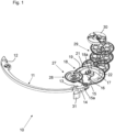
- the mechanism 10 partially illustrated in the figure 1 is an animation mechanism, that is to say a mechanism for purely decorative and entertaining purposes, and preferably an automaton mechanism.
- the mechanism 10 could nevertheless be a clockwork mechanism, for example a complication of the chime type such as a minute repeater.
- the mechanism 10 comprises a mainspring 11 consisting of a simple curved, unwound blade, working in flexion. Compared to the spiral springs of the barrels, such a mainspring makes it possible to simplify and optimize the size. On the other hand, the force it produces as a function of its degree of winding varies more than that of a spiral spring.
- the motor spring 11 is fixed by its base 12 to the frame of the mechanism 10 and ends with a free end portion 13 forming a step.
- the free end portion 13 bears against the handle 14 of a control rack 15 which is pivoted about an axis 15a and whose toothed sector 16 meshes with a pinion 17 with sectoral teeth.
- the pinion 17 is part of a one-way clutch mobile 18 further comprising a wheel 19 coaxial with the pinion 17 and a transmission member 20 integral in rotation with the pinion 17 (cf. Figures 2 and 3 ).
- a ring 21 projecting from the board of the wheel 19 has on its inner surface notches 22 regularly distributed around the axis 18a of the mobile 18.
- the transmission member 20 comprises a base 23 mounted on the axis 18a of the mobile 18 and from which extends a bent arm composed of a rigid radial portion 24 and an elastic circumferential portion 25 connected to the base 23 by the rigid radial portion 24.
- the shape of the free end 26 of the elastic circumferential portion 25 is adapted to that of the notches 22. The free end 26 can thus engage in the notches 22 (cf.
- the transmission member 20 could comprise a second arm symmetrical to the arm 24, 25 with respect to the axis 18a of the one-way clutch mobile 18 and also cooperating with the notches 22.
- the pinion 17 is the input member of a gear train 27 formed by the pinion 17, the wheel 19, a mobile 28 meshing with the wheel 19 and other mobiles not shown, this gear train 27 being arranged to actuate decorative elements of the animation.
- a second gear train 29 may be provided, to connect the wheel 19 of the one-way clutch mobile 18 to a regulating member 30 making it possible to regulate the speed of the gear train 27.
- the control rake 15 comprises, in addition to the handle 14 and the toothed sector 16, a heel 31 on which a manual actuating member (not shown) of the pusher or other type can act directly or indirectly.
- the manual actuator see arrow on the figure 3
- the latter pivots the control rack 15 in the direction corresponding to the clockwise direction in the figures, which rotates the pinion 17 and the transmission member 20 in the counterclockwise direction without driving the wheel 19 and therefore without driving the rest of the gear train 27, and which moves the end portion 13 of the mainspring 11 in the direction indicated by the arrow, thus arming the mainspring 11.
- the user can, by means of the manual actuating member, move the control rack 15 from an extreme position illustrated in figure 2 to another extreme position illustrated in the figure 3 , these two extreme positions being defined by stops (not shown). Simultaneously, the end portion 13 of the mainspring 11 is moved between two extreme positions, the first of these positions ( figure 2 ) corresponding to a disarmed state of the mainspring 11, the second of these positions ( figure 3 ) corresponding to an armed state of the mainspring 11.
- the control rack 15 and the pinion 17 together form a non-circular gear.
- the toothing of the control rack 15 is not on a circle centered on the axis of rotation 15a of the control rack 15 and the toothing of the pinion 17 is not on a circle centered on the axis of rotation 18a of the pinion 17.
- the gear ratio between the control rack 15 and the pinion 17 varies in the same direction as the force of the mainspring 11, i.e. it decreases when the mainspring 11 relaxes. In this way, the gear train 27 is driven with a constant torque, at least more constant than if the gear formed by the control rack 15 and the pinion 17 were circular.
- the gear ratio between the drive rake 15 and the pinion 17, from the relative extreme position illustrated in figure 3 to that illustrated in the figure 2 varies (decreases) by at least 15%, preferably by at least 20%, preferably by at least 25%.
- this variation of the gear ratio can be adapted to the variation of force of the mainspring 11, whether it is lower or higher.
- the gear ratio between the control rack 15 and the pinion 17 varies in a non-monotonic manner, for example to take into account, as an alternative or in addition to the variation in force of the mainspring 11, a torque peak required by the animation at a certain moment.
- the manual actuating member could act on the end portion 13 of the mainspring 11 other than via the control rack 15, for example by cooperating with an extension that this end portion 13 would include, and a return spring could keep the handle 14 of the control rack 15 in contact with this end portion 13.
- the mainspring 11 could have a shape other than that shown and be armed by a force applied at a point distant from its ends.
- the invention could also be applied to a mechanism not including a one-way clutch and in which, like the control rack 15, the gear train 27 would move back and forth.
Landscapes
- Physics & Mathematics (AREA)
- General Physics & Mathematics (AREA)
- Acoustics & Sound (AREA)
- Engineering & Computer Science (AREA)
- Multimedia (AREA)
- Toys (AREA)
Abstract
Description
- La présente invention concerne un mécanisme d'horlogerie ou d'animation, plus particulièrement un mécanisme d'horlogerie ou d'animation dont le ressort moteur comprend une portion, typiquement une portion d'extrémité, qui est déplaçable par un utilisateur dans un sens pour armer le ressort moteur et qui, dès qu'elle est libérée, est déplacée dans le sens opposé par la détente du ressort moteur, ce déplacement dans le sens opposé entraînant un rouage du mécanisme. Le mécanisme peut être par exemple un mécanisme d'automate ou un mécanisme de répétition à minutes.
- Dans un tel mécanisme, la force délivrée par le ressort moteur pendant sa détente n'est pas constante, et varie même rapidement d'une force maximale à une force minimale. Cette variation de force se transmet dans le rouage. Elle doit donc être anticipée lors de la conception du mécanisme par un dimensionnement adapté des différents composants qui peut être difficile à trouver, surtout lorsque le ressort moteur est sous la forme d'une simple lame, dont la force est moins stable que celle d'un ressort en spirale classique.
- La présente invention vise à proposer une solution qui permette au rouage d'un mécanisme d'horlogerie ou d'animation de recevoir une force d'entraînement constante ou plus constante.
- A cette fin, la présente invention a pour objet un mécanisme d'horlogerie ou d'animation comprenant un ressort moteur, un rouage et un organe de commande engrenant avec un organe d'entrée du rouage, le ressort moteur comprenant une portion qui est déplaçable par un utilisateur d'une première position extrême à une deuxième position extrême pour armer le ressort moteur et qui, dès qu'elle est libérée, revient à la première position extrême sous l'effet de la détente du ressort moteur, ce retour de ladite portion à la première position extrême déplaçant l'organe de commande d'une troisième position extrême à une quatrième position extrême, ce déplacement de l'organe de commande de la troisième à la quatrième position extrême entraînant l'organe d'entrée et donc le rouage, l'organe de commande étant agencé pour se déplacer de la quatrième à la troisième position extrême lorsque ladite portion du ressort moteur est déplacée par l'utilisateur de la première à la deuxième position extrême, l'organe de commande formant avec l'organe d'entrée un engrenage non circulaire.
- Grâce à l'engrenage non circulaire, la variation de la force délivrée par le ressort moteur peut être compensée au moins partiellement pour que le rouage reçoive au final une force sensiblement constante. Il est aussi possible d'utiliser l'engrenage non circulaire pour lisser un ou des pics de force que génère le mécanisme.
- Typiquement, le rapport d'engrenage entre l'organe de commande et l'organe d'entrée, lorsque l'organe de commande se déplace de la troisième à la quatrième position extrême, varie dans le même sens que la force du ressort moteur. Avantageusement, ce rapport d'engrenage, de la troisième position extrême à la quatrième position extrême de l'organe de commande, varie d'au moins 15%, de préférence d'au moins 20%, de préférence d'au moins 25%.
- Ladite portion du ressort moteur est par exemple une portion d'extrémité.
- Afin d'optimiser l'encombrement, le ressort moteur est de préférence une lame non enroulée, courbe ou droite.
- De préférence, le ressort moteur et l'organe de commande sont en contact. Un tel agencement simplifie en effet la construction du mécanisme.
- Selon une autre caractéristique avantageuse, ladite portion du ressort moteur est déplaçable par l'utilisateur de la première position extrême à la deuxième position extrême par l'intermédiaire de l'organe de commande.
- Dans un exemple typique de réalisation, l'organe d'entrée fait partie d'un mobile d'embrayage unidirectionnel du rouage qui découple l'organe d'entrée du reste du rouage lorsque l'organe de commande se déplace de la quatrième position extrême à la troisième position extrême.
- L'organe de commande est par exemple un râteau.
- L'organe d'entrée est par exemple un pignon ou roue non circulaire.
- Selon des applications particulières de l'invention, le mécanisme est un mécanisme d'automate ou un mécanisme de sonnerie.
- La présente invention propose en outre une pièce d'horlogerie, telle qu'une montre ou une pendulette, comprenant un mécanisme tel que défini ci-dessus.
- D'autres caractéristiques et avantages de la présente invention apparaîtront à la lecture de la description détaillée suivante faite en référence aux dessins annexés dans lesquels :
- la
figure 1 est une vue en perspective d'une partie d'un mécanisme d'horlogerie ou d'animation selon un mode de réalisation particulier l'invention ; - les
figures 2 et 3 sont des vues planes montrant les interactions entre un ressort moteur, un râteau de commande et un mobile d'embrayage unidirectionnel du mécanisme illustré à lafigure 1 . - Le mécanisme 10 illustré partiellement à la
figure 1 est un mécanisme d'animation, c'est-à-dire un mécanisme à but purement décoratif et divertissant, et de préférence un mécanisme d'automate. Le mécanisme 10 pourrait néanmoins être un mécanisme d'horlogerie, par exemple une complication du type sonnerie telle qu'une répétition à minutes. - Le mécanisme 10 comprend un ressort moteur 11 constitué d'une simple lame courbe, non enroulée, travaillant en flexion. Par rapport aux ressorts en spirale des barillets, un tel ressort moteur permet de simplifier et d'optimiser l'encombrement. En revanche, la force qu'il produit en fonction de son degré d'armage varie plus que celle d'un ressort en spirale.
- Le ressort moteur 11 est fixé par sa base 12 au bâti du mécanisme 10 et se termine par une portion d'extrémité libre 13 formant un décrochement. La portion d'extrémité libre 13 est en appui contre le manche 14 d'un râteau de commande 15 qui est pivoté autour d'un axe 15a et dont le secteur denté 16 engrène avec un pignon 17 à denture sectorielle.
- Le pignon 17 fait partie d'un mobile d'embrayage unidirectionnel 18 comprenant en outre une roue 19 coaxiale avec le pignon 17 et un organe de transmission 20 solidaire en rotation du pignon 17 (cf.
figures 2 et 3 ). Un anneau 21 faisant saillie sur la planche de la roue 19 présente sur sa surface intérieure des encoches 22 régulièrement réparties autour de l'axe 18a du mobile 18. L'organe de transmission 20 comprend une base 23 montée sur l'axe 18a du mobile 18 et de laquelle s'étend un bras coudé composé d'une portion radiale rigide 24 et d'une portion circonférentielle élastique 25 reliée à la base 23 par la portion radiale rigide 24. La forme de l'extrémité libre 26 de la portion circonférentielle élastique 25 est adaptée à celle des encoches 22. L'extrémité libre 26 peut ainsi s'engager dans les encoches 22 (cf.figure 2 ) pour permettre à l'organe de transmission 20 de pousser la roue 19 à la manière d'un cliquet lorsque le pignon 17 et l'organe de transmission 20 tournent dans le sens correspondant au sens horaire des figures. Lorsque le pignon 17 et l'organe de transmission 20 tournent dans l'autre sens, l'extrémité libre 26 sort de l'encoche 22 où elle se trouve en faisant fléchir la portion circonférentielle élastique 25 et glisse sur la surface intérieure de l'anneau 21 sans entraîner la roue 19. L'organe de transmission 20 pourrait comprendre un deuxième bras symétrique du bras 24, 25 par rapport à l'axe 18a du mobile d'embrayage unidirectionnel 18 et coopérant lui aussi avec les encoches 22. - Le pignon 17 est l'organe d'entrée d'un rouage 27 formé du pignon 17, de la roue 19, d'un mobile 28 engrenant avec la roue 19 et d'autres mobiles non représentés, ce rouage 27 étant agencé pour actionner des éléments décoratifs de l'animation. Un deuxième rouage 29 peut être prévu, pour relier la roue 19 du mobile d'embrayage unidirectionnel 18 à un organe régulateur 30 permettant de réguler la vitesse du rouage 27.
- Le râteau de commande 15 comprend, en plus du manche 14 et du secteur denté 16, un talon 31 sur lequel peut agir directement ou indirectement un organe d'actionnement manuel (non représenté) du type poussoir ou autre. Lorsque l'utilisateur actionne l'organe d'actionnement manuel (voir la flèche sur la
figure 3 ), ce dernier fait pivoter le râteau de commande 15 dans le sens correspondant au sens horaire sur les figures, ce qui fait tourner le pignon 17 et l'organe de transmission 20 dans le sens antihoraire sans entraîner la roue 19 donc sans entraîner le reste du rouage 27, et ce qui déplace la portion d'extrémité 13 du ressort moteur 11 dans le sens indiqué par la flèche, armant ainsi le ressort moteur 11. Plus concrètement, l'utilisateur peut, par l'intermédiaire de l'organe d'actionnement manuel, déplacer le râteau de commande 15 d'une position extrême illustrée à lafigure 2 à une autre position extrême illustrée à lafigure 3 , ces deux positions extrêmes étant définies par des butées (non représentées). Simultanément, la portion d'extrémité 13 du ressort moteur 11 est déplacée entre deux positions extrêmes, la première de ces positions (figure 2 ) correspondant à un état désarmé du ressort moteur 11, la deuxième de ces positions (figure 3 ) correspondant à un état armé du ressort moteur 11. - Lorsque le râteau de commande 15 et la portion d'extrémité 13 du ressort moteur 11 sont dans leur position extrême de la
figure 3 , l'extrémité libre 26 du bras 24, 25 est non seulement sortie de l'encoche 22 où elle se trouvait mais s'est également déplacée au-delà de l'encoche adjacente dans le sens antihoraire. Dès que l'utilisateur relâche l'organe d'actionnement manuel, le ressort moteur 11 se détend en repoussant le râteau de commande 15 par sa portion d'extrémité 13, lequel râteau de commande 15 fait pivoter le pignon 17 et l'organe de transmission 20 dans le sens horaire. Pendant ce déplacement, l'extrémité libre 26 du bras 24, 25 s'engage dans ladite encoche adjacente et pousse la roue 19 dans le sens horaire, entraînant ainsi par le rouage 27 les éléments décoratifs de l'animation, l'animation s'arrêtant lorsque le râteau de commande 15 atteint sa position extrême illustrée à lafigure 2 . - Conformément à l'invention, le râteau de commande 15 et le pignon 17 forment ensemble un engrenage non circulaire. En d'autres termes, la denture du râteau de commande 15 n'est pas sur un cercle centré sur l'axe de rotation 15a du râteau de commande 15 et la denture du pignon 17 n'est pas sur un cercle centré sur l'axe de rotation 18a du pignon 17. Cela conduit à un rapport d'engrenage variable entre les deux positions relatives extrêmes du râteau de commande 15 et du pignon 17. Typiquement, le rapport d'engrenage entre le râteau de commande 15 et le pignon 17 varie dans le même sens que la force du ressort moteur 11, c'est-à-dire qu'il diminue lorsque le ressort moteur 11 se détend. De la sorte, le rouage 27 est entraîné avec un couple constant, à tout le moins plus constant que si l'engrenage formé par le râteau de commande 15 et le pignon 17 était circulaire.
- Dans des exemples de réalisation typiques, le rapport d'engrenage entre le râteau de commande 15 et le pignon 17, de la position extrême relative illustrée à la
figure 3 à celle illustrée à lafigure 2 , varie (diminue) d'au moins 15%, de préférence d'au moins 20%, de préférence d'au moins 25%. Naturellement, cette variation du rapport d'engrenage peut être adaptée à la variation de force du ressort moteur 11, qu'elle soit plus faible ou plus élevée. - Dans d'autres exemples de réalisation, le rapport d'engrenage entre le râteau de commande 15 et le pignon 17 varie d'une manière non monotone, par exemple pour tenir compte, en alternative ou en complément à la variation de force du ressort moteur 11, d'un pic de couple que nécessite l'animation à un certain moment.
- L'homme du métier comprendra que des modifications pourraient être apportées à l'invention décrite ci-dessus sans sortir du cadre de l'invention revendiquée. En particulier, l'organe d'actionnement manuel pourrait agir sur la portion d'extrémité 13 du ressort moteur 11 autrement que par l'intermédiaire du râteau de commande 15, par exemple en coopérant avec une extension que comporterait cette portion d'extrémité 13, et un ressort de rappel pourrait maintenir le manche 14 du râteau de commande 15 en contact avec cette portion d'extrémité 13. Par ailleurs, le ressort moteur 11 pourrait avoir une autre forme que celle représentée et être armé par une force appliquée en un point distant de ses extrémités. On pourrait aussi appliquer l'invention à un mécanisme ne comprenant pas d'embrayage unidirectionnel et dans lequel, comme le râteau de commande 15, le rouage 27 effectuerait des va-et vient.
Claims (12)
- Mécanisme d'horlogerie ou d'animation comprenant un ressort moteur (11), un rouage (27) et un organe de commande (15) engrenant avec un organe d'entrée (17) du rouage (27), le ressort moteur (11) comprenant une portion (13) qui est déplaçable par un utilisateur d'une première position extrême à une deuxième position extrême pour armer le ressort moteur (11) et qui, dès qu'elle est libérée, revient à la première position extrême sous l'effet de la détente du ressort moteur (11), ce retour de ladite portion (13) à la première position extrême déplaçant l'organe de commande (15) d'une troisième position extrême à une quatrième position extrême, ce déplacement de l'organe de commande (15) de la troisième à la quatrième position extrême entraînant l'organe d'entrée (17) et donc le rouage (27), l'organe de commande (15) étant agencé pour se déplacer de la quatrième à la troisième position extrême lorsque ladite portion (13) du ressort moteur (11) est déplacée par l'utilisateur de la première à la deuxième position extrême, l'organe de commande (15) formant avec l'organe d'entrée (17) un engrenage non circulaire.
- Mécanisme selon la revendication 1, dans lequel le rapport d'engrenage entre l'organe de commande (15) et l'organe d'entrée (17), lorsque l'organe de commande (15) se déplace de la troisième à la quatrième position extrême, varie dans le même sens que la force du ressort moteur (11).
- Mécanisme selon la revendication 2, dans lequel le rapport d'engrenage entre l'organe de commande (15) et l'organe d'entrée (17), de la troisième position extrême à la quatrième position extrême de l'organe de commande (15), varie d'au moins 15%, de préférence d'au moins 20%, de préférence d'au moins 25%.
- Mécanisme selon l'une des revendications 1 à 3, dans lequel ladite portion (13) du ressort moteur (11) est une portion d'extrémité.
- Mécanisme selon l'une des revendications 1 à 4, dans lequel le ressort moteur (11) est une lame non enroulée.
- Mécanisme selon l'une des revendications 1 à 5, dans lequel le ressort moteur (11) et l'organe de commande (15) sont en contact.
- Mécanisme selon l'une des revendications 1 à 6, dans lequel ladite portion (13) du ressort moteur (11) est déplaçable par l'utilisateur de la première position extrême à la deuxième position extrême par l'intermédiaire de l'organe de commande (15).
- Mécanisme selon l'une des revendications 1 à 7, dans lequel l'organe d'entrée (17) fait partie d'un mobile d'embrayage unidirectionnel (18) du rouage (27) qui découple l'organe d'entrée (17) du reste du rouage (27) lorsque l'organe de commande (15) se déplace de la quatrième position extrême à la troisième position extrême.
- Mécanisme selon l'une des revendications 1 à 8, dans lequel l'organe de commande (15) est un râteau.
- Mécanisme selon l'une des revendications 1 à 9, dans lequel l'organe d'entrée (17) est un pignon ou roue non circulaire.
- Mécanisme selon l'une des revendications 1 à 10, consistant en un mécanisme d'automate ou un mécanisme de sonnerie.
- Pièce d'horlogerie comprenant un mécanisme selon l'une des revendications 1 à 11.
Applications Claiming Priority (1)
| Application Number | Priority Date | Filing Date | Title |
|---|---|---|---|
| CH000786/2023A CH720968A1 (fr) | 2023-07-21 | 2023-07-21 | Mécanisme d'horlogerie ou d'animation |
Publications (1)
| Publication Number | Publication Date |
|---|---|
| EP4495706A1 true EP4495706A1 (fr) | 2025-01-22 |
Family
ID=87555143
Family Applications (1)
| Application Number | Title | Priority Date | Filing Date |
|---|---|---|---|
| EP24189315.5A Pending EP4495706A1 (fr) | 2023-07-21 | 2024-07-18 | Mécanisme d'horlogerie ou d'animation |
Country Status (2)
| Country | Link |
|---|---|
| EP (1) | EP4495706A1 (fr) |
| CH (1) | CH720968A1 (fr) |
Citations (4)
| Publication number | Priority date | Publication date | Assignee | Title |
|---|---|---|---|---|
| US4020625A (en) * | 1976-01-02 | 1977-05-03 | The Singer Company | Expanded scale timer |
| FR2384291A1 (fr) * | 1977-03-17 | 1978-10-13 | Diehl | Mecanisme de minuterie |
| WO2023223193A1 (fr) * | 2022-05-16 | 2023-11-23 | Lvmh Swiss Manufactures Sa | Montre-chronographe |
| WO2024095067A1 (fr) * | 2022-11-04 | 2024-05-10 | Van Cleef & Arpels | Dispositif d'entraînement pour mécanisme horloger |
-
2023
- 2023-07-21 CH CH000786/2023A patent/CH720968A1/fr unknown
-
2024
- 2024-07-18 EP EP24189315.5A patent/EP4495706A1/fr active Pending
Patent Citations (4)
| Publication number | Priority date | Publication date | Assignee | Title |
|---|---|---|---|---|
| US4020625A (en) * | 1976-01-02 | 1977-05-03 | The Singer Company | Expanded scale timer |
| FR2384291A1 (fr) * | 1977-03-17 | 1978-10-13 | Diehl | Mecanisme de minuterie |
| WO2023223193A1 (fr) * | 2022-05-16 | 2023-11-23 | Lvmh Swiss Manufactures Sa | Montre-chronographe |
| WO2024095067A1 (fr) * | 2022-11-04 | 2024-05-10 | Van Cleef & Arpels | Dispositif d'entraînement pour mécanisme horloger |
Also Published As
| Publication number | Publication date |
|---|---|
| CH720968A1 (fr) | 2025-01-31 |
Similar Documents
| Publication | Publication Date | Title |
|---|---|---|
| EP2214065B1 (fr) | Mouvement d'horlogerie muni d'une alarme vibrante | |
| CH709508B1 (fr) | Mouvement horloger muni d'un mécanisme d'entraînement d'un indicateur analogique à déplacement périodique ou intermittent. | |
| EP3705949A1 (fr) | Mecanisme limiteur de couple d'horlogerie | |
| EP1978419B1 (fr) | Dispositif de remontage comprenant un accouplement à sens unique | |
| EP2226687B1 (fr) | Dispositif de débrayage pour mécanisme horloger, et mouvement de montre comportant ce dispositif | |
| CH720968A1 (fr) | Mécanisme d'horlogerie ou d'animation | |
| EP1562086B1 (fr) | Mécanisme indicateur de réserve de marche | |
| CH717217A2 (fr) | Mécanisme de réglage de balancier à même de redémarrer le fonctionnement du balancier, mouvement et pièce d'horlogerie le comprenant. | |
| EP2137578B1 (fr) | Organe moteur avec ressort helicoidal | |
| EP2096504A2 (fr) | Mécanisme d'affichage des secondes mortes | |
| EP4092492B1 (fr) | Mouvement horloger comprenant une génératrice | |
| EP3761122B1 (fr) | Mobile d'échappement horloger, mécanisme d'échappement et pièce d'horlogerie associés | |
| CH720212B1 (fr) | Mouvement horloger comprenant un module de liaison cinématique interposé entre un dispositif de sélection et de commande de fonctions et un dispositif d'affichage | |
| EP2488921B1 (fr) | Source d'énergie pour sonnerie et pièce d'horlogerie munie d'une telle source d'énergie | |
| EP0082110A1 (fr) | Montre électronique avec ou sans aiguilles de secondes | |
| EP1353244B1 (fr) | Montre comportant une boîte de forme allongée | |
| CH712451B1 (fr) | Mécanisme de remontage et de mise à l'heure d'un mouvement horloger. | |
| EP3783444B1 (fr) | Mécanisme horloger comprenant un dispositif de blocage | |
| EP3825786B1 (fr) | Mécanisme d'affichage d'une pièce d'horlogerie | |
| CH714617A2 (fr) | Mouvement et pièce d'horlogerie. | |
| CH705047B1 (fr) | Structure de ressort de rappel, mécanisme de remontage manuel comprenant une telle structure et pièce d'horlogerie comprenant un tel mécanisme. | |
| CH722200A2 (fr) | Pièce d'horlogerie comprenant un compteur d'une unité de temps | |
| EP4383013A1 (fr) | Dispositif horloger de transformation d'une première rotation en une deuxième rotation | |
| EP4513274A1 (fr) | Mouvement horloger | |
| CH720496B1 (fr) | Mécanisme d'entraînement d'affichage horloger |
Legal Events
| Date | Code | Title | Description |
|---|---|---|---|
| PUAI | Public reference made under article 153(3) epc to a published international application that has entered the european phase |
Free format text: ORIGINAL CODE: 0009012 |
|
| STAA | Information on the status of an ep patent application or granted ep patent |
Free format text: STATUS: THE APPLICATION HAS BEEN PUBLISHED |
|
| AK | Designated contracting states |
Kind code of ref document: A1 Designated state(s): AL AT BE BG CH CY CZ DE DK EE ES FI FR GB GR HR HU IE IS IT LI LT LU LV MC ME MK MT NL NO PL PT RO RS SE SI SK SM TR |
|
| REG | Reference to a national code |
Ref country code: HK Ref legal event code: DE Ref document number: 40114924 Country of ref document: HK |
|
| STAA | Information on the status of an ep patent application or granted ep patent |
Free format text: STATUS: REQUEST FOR EXAMINATION WAS MADE |
|
| 17P | Request for examination filed |
Effective date: 20250502 |