EP4495700A1 - Image carrier unit and image forming apparatus - Google Patents
Image carrier unit and image forming apparatus Download PDFInfo
- Publication number
- EP4495700A1 EP4495700A1 EP24158641.1A EP24158641A EP4495700A1 EP 4495700 A1 EP4495700 A1 EP 4495700A1 EP 24158641 A EP24158641 A EP 24158641A EP 4495700 A1 EP4495700 A1 EP 4495700A1
- Authority
- EP
- European Patent Office
- Prior art keywords
- image carrier
- image
- carrier unit
- transporter
- forming apparatus
- Prior art date
- Legal status (The legal status is an assumption and is not a legal conclusion. Google has not performed a legal analysis and makes no representation as to the accuracy of the status listed.)
- Pending
Links
Images



Classifications
-
- G—PHYSICS
- G03—PHOTOGRAPHY; CINEMATOGRAPHY; ANALOGOUS TECHNIQUES USING WAVES OTHER THAN OPTICAL WAVES; ELECTROGRAPHY; HOLOGRAPHY
- G03G—ELECTROGRAPHY; ELECTROPHOTOGRAPHY; MAGNETOGRAPHY
- G03G21/00—Arrangements not provided for by groups G03G13/00 - G03G19/00, e.g. cleaning, elimination of residual charge
- G03G21/0005—Arrangements not provided for by groups G03G13/00 - G03G19/00, e.g. cleaning, elimination of residual charge for removing solid developer or debris from the electrographic recording medium
- G03G21/0011—Arrangements not provided for by groups G03G13/00 - G03G19/00, e.g. cleaning, elimination of residual charge for removing solid developer or debris from the electrographic recording medium using a blade; Details of cleaning blades, e.g. blade shape, layer forming
-
- G—PHYSICS
- G03—PHOTOGRAPHY; CINEMATOGRAPHY; ANALOGOUS TECHNIQUES USING WAVES OTHER THAN OPTICAL WAVES; ELECTROGRAPHY; HOLOGRAPHY
- G03G—ELECTROGRAPHY; ELECTROPHOTOGRAPHY; MAGNETOGRAPHY
- G03G21/00—Arrangements not provided for by groups G03G13/00 - G03G19/00, e.g. cleaning, elimination of residual charge
- G03G21/16—Mechanical means for facilitating the maintenance of the apparatus, e.g. modular arrangements
-
- G—PHYSICS
- G03—PHOTOGRAPHY; CINEMATOGRAPHY; ANALOGOUS TECHNIQUES USING WAVES OTHER THAN OPTICAL WAVES; ELECTROGRAPHY; HOLOGRAPHY
- G03G—ELECTROGRAPHY; ELECTROPHOTOGRAPHY; MAGNETOGRAPHY
- G03G15/00—Apparatus for electrographic processes using a charge pattern
- G03G15/01—Apparatus for electrographic processes using a charge pattern for producing multicoloured copies
- G03G15/0142—Structure of complete machines
-
- G—PHYSICS
- G03—PHOTOGRAPHY; CINEMATOGRAPHY; ANALOGOUS TECHNIQUES USING WAVES OTHER THAN OPTICAL WAVES; ELECTROGRAPHY; HOLOGRAPHY
- G03G—ELECTROGRAPHY; ELECTROPHOTOGRAPHY; MAGNETOGRAPHY
- G03G15/00—Apparatus for electrographic processes using a charge pattern
- G03G15/06—Apparatus for electrographic processes using a charge pattern for developing
- G03G15/08—Apparatus for electrographic processes using a charge pattern for developing using a solid developer, e.g. powder developer
- G03G15/0806—Apparatus for electrographic processes using a charge pattern for developing using a solid developer, e.g. powder developer on a donor element, e.g. belt, roller
-
- G—PHYSICS
- G03—PHOTOGRAPHY; CINEMATOGRAPHY; ANALOGOUS TECHNIQUES USING WAVES OTHER THAN OPTICAL WAVES; ELECTROGRAPHY; HOLOGRAPHY
- G03G—ELECTROGRAPHY; ELECTROPHOTOGRAPHY; MAGNETOGRAPHY
- G03G15/00—Apparatus for electrographic processes using a charge pattern
- G03G15/50—Machine control of apparatus for electrographic processes using a charge pattern, e.g. regulating differents parts of the machine, multimode copiers, microprocessor control
- G03G15/5016—User-machine interface; Display panels; Control console
-
- G—PHYSICS
- G03—PHOTOGRAPHY; CINEMATOGRAPHY; ANALOGOUS TECHNIQUES USING WAVES OTHER THAN OPTICAL WAVES; ELECTROGRAPHY; HOLOGRAPHY
- G03G—ELECTROGRAPHY; ELECTROPHOTOGRAPHY; MAGNETOGRAPHY
- G03G21/00—Arrangements not provided for by groups G03G13/00 - G03G19/00, e.g. cleaning, elimination of residual charge
- G03G21/10—Collecting or recycling waste developer
- G03G21/105—Arrangements for conveying toner waste
-
- G—PHYSICS
- G03—PHOTOGRAPHY; CINEMATOGRAPHY; ANALOGOUS TECHNIQUES USING WAVES OTHER THAN OPTICAL WAVES; ELECTROGRAPHY; HOLOGRAPHY
- G03G—ELECTROGRAPHY; ELECTROPHOTOGRAPHY; MAGNETOGRAPHY
- G03G15/00—Apparatus for electrographic processes using a charge pattern
- G03G15/06—Apparatus for electrographic processes using a charge pattern for developing
- G03G15/08—Apparatus for electrographic processes using a charge pattern for developing using a solid developer, e.g. powder developer
- G03G15/0822—Arrangements for preparing, mixing, supplying or dispensing developer
- G03G15/0887—Arrangements for conveying and conditioning developer in the developing unit, e.g. agitating, removing impurities or humidity
- G03G15/0891—Arrangements for conveying and conditioning developer in the developing unit, e.g. agitating, removing impurities or humidity for conveying or circulating developer, e.g. augers
-
- G—PHYSICS
- G03—PHOTOGRAPHY; CINEMATOGRAPHY; ANALOGOUS TECHNIQUES USING WAVES OTHER THAN OPTICAL WAVES; ELECTROGRAPHY; HOLOGRAPHY
- G03G—ELECTROGRAPHY; ELECTROPHOTOGRAPHY; MAGNETOGRAPHY
- G03G21/00—Arrangements not provided for by groups G03G13/00 - G03G19/00, e.g. cleaning, elimination of residual charge
- G03G21/16—Mechanical means for facilitating the maintenance of the apparatus, e.g. modular arrangements
- G03G21/18—Mechanical means for facilitating the maintenance of the apparatus, e.g. modular arrangements using a processing cartridge, whereby the process cartridge comprises at least two image processing means in a single unit
- G03G21/1839—Means for handling the process cartridge in the apparatus body
- G03G21/1842—Means for handling the process cartridge in the apparatus body for guiding and mounting the process cartridge, positioning, alignment, locks
- G03G21/1846—Means for handling the process cartridge in the apparatus body for guiding and mounting the process cartridge, positioning, alignment, locks using a handle for carrying or pulling out of the main machine, legs of casings
-
- G—PHYSICS
- G03—PHOTOGRAPHY; CINEMATOGRAPHY; ANALOGOUS TECHNIQUES USING WAVES OTHER THAN OPTICAL WAVES; ELECTROGRAPHY; HOLOGRAPHY
- G03G—ELECTROGRAPHY; ELECTROPHOTOGRAPHY; MAGNETOGRAPHY
- G03G21/00—Arrangements not provided for by groups G03G13/00 - G03G19/00, e.g. cleaning, elimination of residual charge
- G03G21/16—Mechanical means for facilitating the maintenance of the apparatus, e.g. modular arrangements
- G03G21/18—Mechanical means for facilitating the maintenance of the apparatus, e.g. modular arrangements using a processing cartridge, whereby the process cartridge comprises at least two image processing means in a single unit
- G03G21/1839—Means for handling the process cartridge in the apparatus body
- G03G21/1842—Means for handling the process cartridge in the apparatus body for guiding and mounting the process cartridge, positioning, alignment, locks
- G03G21/185—Means for handling the process cartridge in the apparatus body for guiding and mounting the process cartridge, positioning, alignment, locks the process cartridge being mounted parallel to the axis of the photosensitive member
-
- G—PHYSICS
- G03—PHOTOGRAPHY; CINEMATOGRAPHY; ANALOGOUS TECHNIQUES USING WAVES OTHER THAN OPTICAL WAVES; ELECTROGRAPHY; HOLOGRAPHY
- G03G—ELECTROGRAPHY; ELECTROPHOTOGRAPHY; MAGNETOGRAPHY
- G03G2215/00—Apparatus for electrophotographic processes
- G03G2215/08—Details of powder developing device not concerning the development directly
- G03G2215/0802—Arrangements for agitating or circulating developer material
- G03G2215/0816—Agitator type
- G03G2215/0827—Augers
-
- G—PHYSICS
- G03—PHOTOGRAPHY; CINEMATOGRAPHY; ANALOGOUS TECHNIQUES USING WAVES OTHER THAN OPTICAL WAVES; ELECTROGRAPHY; HOLOGRAPHY
- G03G—ELECTROGRAPHY; ELECTROPHOTOGRAPHY; MAGNETOGRAPHY
- G03G2221/00—Processes not provided for by group G03G2215/00, e.g. cleaning or residual charge elimination
- G03G2221/16—Mechanical means for facilitating the maintenance of the apparatus, e.g. modular arrangements and complete machine concepts
- G03G2221/18—Cartridge systems
- G03G2221/183—Process cartridge
- G03G2221/1846—Process cartridge using a handle for carrying or pulling out of the main machine
Definitions
- the present disclosure relates to an image carrier unit and an image forming apparatus.
- Japanese Unexamined Patent Application Publication No. 2009-93099 discloses an electrophotographic image forming apparatus including a collector that collects a detachable unit containing a toner and/or a carrier by enclosing the unit when replacing the unit.
- the grip portion of the image carrier unit may be provided so that the user's hand is not stained. If the grip portion is a separate member, the external size of the image carrier unit increases and the size of a housing space in the image forming apparatus is not easily reduced. Thus, it is difficult to achieve space saving.
- an image carrier unit comprising: an image carrier configured to carry an image on a surface of the image carrier; a removal member configured to remove an adherent adhering to the surface of the image carrier; a transporter configured to transport the adherent removed by the removal member in an axial direction by axial rotation to discharge the adherent; and a grip portion to be gripped by a user to insert the image carrier unit into or remove the image carrier unit from an image forming apparatus configured to form, on a recording medium, the image on the image carrier, wherein the grip portion comprises a recessed portion that constitutes an outer surface while receding toward the transporter in a cross section intersecting the axial direction of the transporter, and has a curved wall serving as a partition from the transporter.
- the recessed portion is formed so that a thickness of the curved wall in the cross section does not change.
- the recessed portion has a bottom surface positioned deeper than a position of a rotation axis of the transporter.
- the grip portion comprises a reinforcing portion connected to the curved wall.
- the recessed portion comprises a first region in which a length in the axial direction is larger, and a second region in which the length in the axial direction is smaller, and the reinforcing portion is formed at a boundary position between the first region and the second region.
- a rib extending in a receding direction of the recessed portion in the cross section is formed on a facing wall that faces the curved wall in the cross section.
- the rib in the image carrier unit according to the sixth aspect, extends in a direction intersecting the receding direction.
- the image carrier unit is inclined by a weight of the image carrier unit relative to the image forming apparatus when the image carrier unit is pulled to a predetermined position in a direction in which the image carrier unit is pulled from the image forming apparatus.
- an image forming apparatus comprising: an image former configured to form an image; and an image carrier unit that constitutes the image former and is insertable into and removable from an apparatus body including the image former.
- the image carrier unit comprises: an image carrier configured to carry an image on a surface of the image carrier; a removal member configured to remove an adherent adhering to the surface of the image carrier; a transporter configured to transport the adherent removed by the removal member in an axial direction by axial rotation to discharge the adherent; and a grip portion to be gripped by a user to insert the image carrier unit into or remove the image carrier unit from the apparatus body, wherein the grip portion comprises a recessed portion that constitutes an outer surface while receding toward the transporter in a cross section intersecting the axial direction of the transporter, and has a curved wall serving as a partition from the transporter.
- space saving may be achieved compared with a case where the grip portion is provided as a separate member.
- the strength may be improved compared with a case without the structure in which the recessed portion is formed so that the thickness of the curved wall in the cross section does not change.
- the operability may be improved compared with a case without the structure in which the recessed portion has the bottom surface positioned deeper than the position of the rotation axis of the transporter.
- the strength may be improved compared with a case without the structure in which the grip portion includes the reinforcing portion connected to the curved wall.
- the strength may be improved compared with a case without the structure in which the recessed portion includes the first region in which the length in the axial direction is larger and the second region in which the length in the axial direction is smaller, and the reinforcing portion is formed at the boundary position between the first region and the second region.
- the insertion and removal work may be facilitated compared with a case without the structure in which the rib extending in the receding direction of the recessed portion in the cross section is formed on the facing wall that faces the curved wall in the cross section.
- the insertion and removal work may be facilitated compared with a case without the structure in which the rib extends in the direction intersecting the receding direction.
- the timing to grip the grip portion may be grasped more easily than in a case without the structure in which the image carrier unit is inclined by the weight of the image carrier unit relative to the image forming apparatus when the image carrier unit is pulled to the predetermined position in the direction in which the image carrier unit is pulled from the image forming apparatus.
- space saving may be achieved compared with a case where the grip portion is provided as a separate member.
- Fig. 1 is a schematic structural diagram of an image forming apparatus 100 according to this exemplary embodiment.
- the image forming apparatus 100 includes a document reading device 1 that reads information on a document G, an image former 2 that forms an image on recording paper S based on the information on the document read by the document reading device 1 (read image), and a paper feeder 3 that sends the recording paper S to be fed to the image former 2.
- the image former 2 and the paper feeder 3 are housed in a body 101, and the document reading device 1 is disposed above the body 101.
- the body 101 includes, at its top, an output paper receiver 102 that receives the output recording paper S on which the image is formed.
- the document reading device 1 includes a housing 103.
- the document reading device 1 includes, at the top of the housing 103, a light transmissive document stage 105 on which the document G is placed, and a document cover 106 that covers the document stage 105 and is openable and closable relative to the housing 103.
- the document cover 106 has an automatic document feeder 107 that transports the document G to a reading position and outputs the read document G, a document tray 108 on which the document G to be sent by the automatic document feeder 107 is placed, and a receiver 109 that receives the document G output by the automatic document feeder 107.
- the image former 2 includes an image forming unit 20 that forms yellow (Y), magenta (M), cyan (C), and black (K) toner images by, for example, an electrophotographic system, an intermediate transfer unit 26 that transports the toner images formed by the image forming unit 20 until they are transferred onto the recording paper S, and a fixing unit 27 that fixes the toner images transferred onto the recording paper S from the intermediate transfer unit 26.
- an image forming unit 20 that forms yellow (Y), magenta (M), cyan (C), and black (K) toner images by, for example, an electrophotographic system
- an intermediate transfer unit 26 that transports the toner images formed by the image forming unit 20 until they are transferred onto the recording paper S
- a fixing unit 27 that fixes the toner images transferred onto the recording paper S from the intermediate transfer unit 26.
- the image forming unit 20 includes photoconductor units 4 associated with the individual colors and represented by broken lines. Each photoconductor unit 4 is attachable to and removable from the body 101 by a user.
- the paper feeder 3 includes drawable containers 31 that contain a plurality of sheets of recording paper S in preset sizes, types, etc., and feeding devices 32 that send the sheets of recording paper S contained in the containers 31 one by one to transport paths.
- a feeding and transport path 28 is provided between the paper feeder 3 and the image former 2 to transport the recording paper S sent from the paper feeder 3 to a second transfer position.
- the document reading device 1 the user places the document G on the document stage 105 or the document tray 108.
- the document reading device 1 starts an operation of reading the document G. That is, the document reading device 1 acquires read information on the document G.
- the image former 2 performs an image forming operation based on the read information on the document G received from the document reading device 1.
- the paper feeder 3 sends out the recording paper S. After the toner images are fixed by the image former 2, the recording paper S is output to the output paper receiver 102.
- the image forming operation is repeated for the number of documents G or the number of images to be formed.
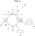
- the image forming unit 20 is described with reference to Fig. 2 . More specifically, each photoconductor unit 4 constituting the image forming unit 20 is described.
- the photoconductor unit 4 is an example of an image carrier unit.
- Fig. 2 illustrates the structure of the photoconductor unit 4 that is viewed from the front side of the image forming apparatus 100.
- the photoconductor unit 4 includes a photoconductor drum 11 that rotates in an arrow direction.
- the photoconductor unit 4 includes a charging roller 12, an exposing device 13, a developing device 14, a transfer roller 15, and a cleaning device 16 as members disposed around the photoconductor drum 11.
- the photoconductor unit 4 may have all of these members but part of the members may be omitted.
- the photoconductor drum 11 is a cylinder.
- a photoconductive layer (not illustrated) is formed on the surface of the cylinder.
- the charging roller 12 is a conductive rubber roller etc. and charges the photoconductor drum 11.
- the exposing device 13 irradiates the photoconductor drum 11 charged by the charging roller 12 with light from a laser light source, a light emitting diode (LED) light source, etc. to form an electrostatic latent image on the surface of the photoconductor drum 11.
- a laser light source a light emitting diode (LED) light source, etc.
- the developing device 14 causes a toner to adhere to the surface of the photoconductor drum 11 to develop the electrostatic latent image formed on the photoconductor drum 11 with the toner in a predetermined color. In this way, a toner image is formed on the surface of the photoconductor drum 11 in this exemplary embodiment.
- the developing device 14 contains a developer.
- the developer is a so-called two-component developer composed of a magnetic carrier and a colored toner.
- a developer container 19 contains the developer to be supplied to the developing device 14.
- a new developer is supplied from the developer container 19 to the developing device 14 through a developer transport path (not illustrated).
- the transfer roller 15 is a conductive rubber roller etc.
- the transfer roller 15 and the photoconductor drum 11 face each other to define a transfer portion T.
- a transfer bias is applied to the transfer roller 15.
- the toner image on the surface of the photoconductor drum 11, that is, the toner image carried by the photoconductor drum 11 is transferred onto a belt of the intermediate transfer unit 26 at the transfer portion T.
- the cleaning device 16 includes a contact member 16A disposed in contact with the photoconductor drum 11, and removes adherents such as a toner on the photoconductor drum 11.
- Fig. 3 is a sectional view illustrating the photoconductor unit 4.
- the photoconductor unit 4 illustrated in Fig. 3 includes a housing 41 and a transport auger 42 in addition to the photoconductor drum 11 and the cleaning device 16.
- the housing 41 is a member serving as the body of the photoconductor unit 4, and rotatably supports the photoconductor drum 11 and the transport auger 42. More specifically, the housing 41 supports the photoconductor drum 11 and the transport auger 42 so that the rotation shaft of the photoconductor drum 11 and the rotation shaft of the transport auger 42 extend in the same direction. The rotation shafts of the photoconductor drum 11 and the transport auger 42 extend in a direction perpendicular to the drawing sheet.
- the housing 41 includes a wall 43 positioned below the transport auger 42 to define a space that houses the transport auger 42.
- the wall 43 is positioned opposite to the photoconductor drum 11 across the transport auger 42.
- the wall 43 is an example of a curved wall.
- the transport auger 42 adjoins the photoconductor drum 11 and a spiral blade is attached around the rotation shaft. When the transport auger 42 rotates, adherents such as a toner removed by the cleaning device 16 are transported in one direction.
- the housing space for the transport auger 42 defined by the wall 43 serves as a collection path.
- the transport auger 42 is an example of a transporter.
- the cleaning device 16 illustrated in Fig. 3 cleans the surface of the photoconductor drum 11 by removing adherents such as a toner adhering to the surface of the photoconductor drum 11.
- the adherents such as a toner removed by the contact member 16A of the cleaning device 16 are collected on the collection path but partially scattered in a toner scattering direction 40.
- the contact member 16A of the cleaning device 16 is an example of a removal member.
- the housing 41 is described in more detail.
- the housing 41 includes a first operation portion 51 and a second operation portion 52 to be operated by the user to insert the photoconductor unit 4 into or remove the photoconductor unit 4 from the image forming apparatus 100.
- the first operation portion 51 is provided at the middle position in a vertical direction V of the housing 41, and the second operation portion 52 is provided at a lower part of the housing 41.
- the first operation portion 51 is formed in a space 53 separated from the transport auger 42 by the wall 43.
- the space 53 for the first operation portion 51 recedes from the outer surface in a receding direction D toward the transport auger 42.
- the cross section illustrated in Fig. 3 intersects the axial direction of the transport auger 42.
- the wall 43 and a bottom surface 44 described later that define the space 53 for the first operation portion 51 are examples of a recessed portion that constitutes the outer surface while receding toward the transport auger 42.
- the housing 41 includes a restrictor 54 that is positioned above the first operation portion 51 and restricts movement of the toner scattered in the toner scattering direction 40 toward the space 53.
- the restrictor 54 is shaped to extend upward in the vertical direction V and also extend in the toner scattering direction 40, and is formed along the axial direction of the transport auger 42 (direction perpendicular to the drawing sheet).
- the second operation portion 52 is positioned at the lower part of the housing 41 and has a flat surface 52a.
- the second operation portion 52 has a protrusion 52b that protrudes in a direction opposite to the first operation portion 51 to enlarge the surface 52a.
- Fig. 4 illustrates an example of how the user holds the photoconductor unit 4 to insert the photoconductor unit 4 into or remove the photoconductor unit 4 from the image forming apparatus 100.
- a thumb LH1 may be put on the first operation portion 51 and the four remaining fingers LH2 may support the second operation portion 52 from below.
- the space 53 is not positioned in the toner scattering direction 40 (see Fig. 3 ), and the toner adhesion amount is reduced by the restrictor 54 (see Fig. 3 ) corresponding to the toner scattering direction 40. Therefore, the toner does not contact the user's hand even if the user touches the first operation portion 51 during replacement of the photoconductor unit 4.
- Fig. 5 is a partially enlarged sectional view of the photoconductor unit 4 for description of the first operation portion 51.
- the first operation portion 51 is formed by using the wall 43. More specifically, the first operation portion 51 is formed by the wall 43 and the bottom surface 44. As illustrated in Fig. 5 , the wall 43 and the bottom surface 44 are disposed at different positions in the vertical direction, and the wall 43 is positioned above the bottom surface 44 in the vertical direction V. The bottom surface 44 faces the wall 43, and is an example of a facing wall.
- the wall 43 serves as a partition from the transport auger 42, and is curved to project toward the space 53.
- the wall 43 is formed so that the thickness does not change in the cross section. Thus, the strength of the wall 43 is improved.
- the bottom surface 44 of the wall 43 includes a portion 53a positioned deeper than a straight line 42b including a rotation axis 42a of the transport auger 42 and extending in the vertical direction V.
- the portion 53a is part of the bottom surface 44 but may be the entire bottom surface 44.
- the bottom surface 44 according to this exemplary embodiment is positioned deeper than the position of the rotation axis 42a. Thus, the operability of the first operation portion 51 to be used by the user is improved.
- Fig. 6 is a perspective view of the housing 41 from the first operation portion 51 side.
- the first operation portion 51 includes a first region 55 that is long in an axial direction J of the transport auger 42 (see, for example, Fig. 3 ), and second regions 56 that are short in the axial direction J.
- a reinforcing portion 57 connected to the wall 43 is formed at a boundary position between the first region 55 and each second region 56. The strength of the photoconductor unit 4 is improved compared with a case where the reinforcing portion 57 is not provided at the boundary position between the first region 55 and the second region 56.
- the strength is further improved when the reinforcing portion 57 is provided not only at the boundary position between the first region 55 and the second region 56 but also between the second regions 56.
- the first operation portion 51 has ribs 58 on the bottom surface 44 that faces the wall 43.
- the ribs 58 extend in the receding direction D.
- the ribs 58 increase the area of contact with the user's finger. Therefore, the photoconductor unit 4 may be inserted into and removed from the image forming apparatus 100 more easily than in a case where the ribs 58 are not provided.
- Fig. 7 is a partial perspective view illustrating a first operation portion 51 according to a modification, and illustrates the housing 41 that is viewed from the first operation portion 51 side as in Fig. 6 .
- the first operation portion 51 has ribs 59 on the bottom surface 44 in place of the ribs 58 (see Fig. 6 ) extending in the receding direction D.
- the ribs 59 extend in a direction intersecting the receding direction D at an angle ⁇ .
- the ribs 59 extend in an oblique direction with respect to the receding direction D, and increase the area of contact with the user's finger and reduce a slip of the finger.
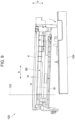
- the posture of the photoconductor unit 4 that is pulled from the body 101 of the image forming apparatus 100 is described with reference to Figs. 8 and 9 .
- the photoconductor unit 4 is pulled by the user's right hand and the first operation portion 51 is held by the user's left hand.
- Figs. 8 and 9 illustrate the postures of the photoconductor unit 4 that is pulled from the image forming apparatus 100.
- the posture of the photoconductor unit 4 thus changes depending on the position of the center of gravity 60 relative to the body 101 when the photoconductor unit 4 is pulled in the pulling direction H.
- the photoconductor unit 4 pulled in the direction H from the image forming apparatus 100 to a predetermined position is inclined by its weight relative to the image forming apparatus 100. Therefore, the user who is pulling the photoconductor unit 4 is visually notified that the rear side of the photoconductor unit 4 in the pulling direction H may be detached from the body 101 if the user continues to pull the photoconductor unit 4.
- the user may grasp the timing to grip the first operation portion 51 and the second operation portion 52 (see Fig. 3 ) of the photoconductor unit 4.
- the pulling direction H is an example of a direction of pulling, and the position where the center of gravity 60 of the photoconductor unit 4 is no longer within the body 101 of the image forming apparatus 100 is an example of the predetermined position.
- space saving may be achieved compared with a case where the grip portion is provided as a separate member.
- the strength may be improved compared with a case without the structure in which the recessed portion is formed so that the thickness of the curved wall in the cross section does not change.
- the operability may be improved compared with a case without the structure in which the recessed portion has the bottom surface positioned deeper than the position of the rotation axis of the transporter.
- the strength may be improved compared with a case without the structure in which the grip portion includes the reinforcing portion connected to the curved wall.
- the strength may be improved compared with a case without the structure in which the recessed portion includes the first region in which the length in the axial direction is larger and the second region in which the length in the axial direction is smaller, and the reinforcing portion is formed at the boundary position between the first region and the second region.
- the insertion and removal work may be facilitated compared with a case without the structure in which the rib extending in the receding direction of the recessed portion in the cross section is formed on the facing wall that faces the curved wall in the cross section.
- the insertion and removal work may be facilitated compared with a case without the structure in which the rib extends in the direction intersecting the receding direction.
- the timing to grip the grip portion may be grasped more easily than in a case without the structure in which the image carrier unit is inclined by the weight of the image carrier unit relative to the image forming apparatus when the image carrier unit is pulled to the predetermined position in the direction in which the image carrier unit is pulled from the image forming apparatus.
- space saving may be achieved compared with a case where the grip portion is provided as a separate member.
Landscapes
- Physics & Mathematics (AREA)
- General Physics & Mathematics (AREA)
- Engineering & Computer Science (AREA)
- Life Sciences & Earth Sciences (AREA)
- Environmental & Geological Engineering (AREA)
- Sustainable Development (AREA)
- Microelectronics & Electronic Packaging (AREA)
- Computer Vision & Pattern Recognition (AREA)
- Electrophotography Configuration And Component (AREA)
Abstract
An image carrier unit includes an image carrier configured to carry an image on a surface of the image carrier, a removal member configured to remove an adherent adhering to the surface of the image carrier, a transporter configured to transport the adherent removed by the removal member in an axial direction by axial rotation to discharge the adherent, and a grip portion to be gripped by a user to insert the image carrier unit into or remove the image carrier unit from an image forming apparatus configured to form, on a recording medium, the image on the image carrier. The grip portion includes a recessed portion that constitutes an outer surface while receding toward the transporter in a cross section intersecting the axial direction of the transporter, and has a curved wall serving as a partition from the transporter.
Description
- The present disclosure relates to an image carrier unit and an image forming apparatus.
- For example,
Japanese Unexamined Patent Application Publication No. 2009-93099 - To insert an image carrier unit into or remove the image carrier unit from an image forming apparatus by holding a grip portion of the image carrier unit, the grip portion of the image carrier unit may be provided so that the user's hand is not stained. If the grip portion is a separate member, the external size of the image carrier unit increases and the size of a housing space in the image forming apparatus is not easily reduced. Thus, it is difficult to achieve space saving.
- Accordingly, it is an object of the present disclosure to achieve space saving compared with a case where the grip portion is provided as a separate member.
- According to a first aspect of the present disclosure, there is provided an image carrier unit comprising: an image carrier configured to carry an image on a surface of the image carrier; a removal member configured to remove an adherent adhering to the surface of the image carrier; a transporter configured to transport the adherent removed by the removal member in an axial direction by axial rotation to discharge the adherent; and a grip portion to be gripped by a user to insert the image carrier unit into or remove the image carrier unit from an image forming apparatus configured to form, on a recording medium, the image on the image carrier, wherein the grip portion comprises a recessed portion that constitutes an outer surface while receding toward the transporter in a cross section intersecting the axial direction of the transporter, and has a curved wall serving as a partition from the transporter.
- According to a second aspect of the present disclosure, in the image carrier unit according to the first aspect, the recessed portion is formed so that a thickness of the curved wall in the cross section does not change.
- According to a third aspect of the present disclosure, in the image carrier unit according to the first or second aspect, the recessed portion has a bottom surface positioned deeper than a position of a rotation axis of the transporter.
- According to a fourth aspect of the present disclosure, in the image carrier unit according to any one of the first to third aspects, the grip portion comprises a reinforcing portion connected to the curved wall.
- According to a fifth aspect of the present disclosure, in the image carrier unit according to the fourth aspect, the recessed portion comprises a first region in which a length in the axial direction is larger, and a second region in which the length in the axial direction is smaller, and the reinforcing portion is formed at a boundary position between the first region and the second region.
- According to a sixth aspect of the present disclosure, in the image carrier unit according to any one of the first to third aspects, a rib extending in a receding direction of the recessed portion in the cross section is formed on a facing wall that faces the curved wall in the cross section.
- According to a seventh aspect of the present disclosure, in the image carrier unit according to the sixth aspect, the rib extends in a direction intersecting the receding direction.
- According to an eighth aspect of the present disclosure, in the image carrier unit according to any one of the first to third aspects, the image carrier unit is inclined by a weight of the image carrier unit relative to the image forming apparatus when the image carrier unit is pulled to a predetermined position in a direction in which the image carrier unit is pulled from the image forming apparatus.
- According to a ninth aspect of the present disclosure, there is provided an image forming apparatus comprising: an image former configured to form an image; and an image carrier unit that constitutes the image former and is insertable into and removable from an apparatus body including the image former. The image carrier unit comprises: an image carrier configured to carry an image on a surface of the image carrier; a removal member configured to remove an adherent adhering to the surface of the image carrier; a transporter configured to transport the adherent removed by the removal member in an axial direction by axial rotation to discharge the adherent; and a grip portion to be gripped by a user to insert the image carrier unit into or remove the image carrier unit from the apparatus body, wherein the grip portion comprises a recessed portion that constitutes an outer surface while receding toward the transporter in a cross section intersecting the axial direction of the transporter, and has a curved wall serving as a partition from the transporter.
- According to the first aspect of the present disclosure, space saving may be achieved compared with a case where the grip portion is provided as a separate member.
- According to the second aspect of the present disclosure, the strength may be improved compared with a case without the structure in which the recessed portion is formed so that the thickness of the curved wall in the cross section does not change.
- According to the third aspect of the present disclosure, the operability may be improved compared with a case without the structure in which the recessed portion has the bottom surface positioned deeper than the position of the rotation axis of the transporter.
- According to the fourth aspect of the present disclosure, the strength may be improved compared with a case without the structure in which the grip portion includes the reinforcing portion connected to the curved wall.
- According to the fifth aspect of the present disclosure, the strength may be improved compared with a case without the structure in which the recessed portion includes the first region in which the length in the axial direction is larger and the second region in which the length in the axial direction is smaller, and the reinforcing portion is formed at the boundary position between the first region and the second region.
- According to the sixth aspect of the present disclosure, the insertion and removal work may be facilitated compared with a case without the structure in which the rib extending in the receding direction of the recessed portion in the cross section is formed on the facing wall that faces the curved wall in the cross section.
- According to the seventh aspect of the present disclosure, the insertion and removal work may be facilitated compared with a case without the structure in which the rib extends in the direction intersecting the receding direction.
- According to the eighth aspect of the present disclosure, the timing to grip the grip portion may be grasped more easily than in a case without the structure in which the image carrier unit is inclined by the weight of the image carrier unit relative to the image forming apparatus when the image carrier unit is pulled to the predetermined position in the direction in which the image carrier unit is pulled from the image forming apparatus.
- According to the ninth aspect of the present disclosure, space saving may be achieved compared with a case where the grip portion is provided as a separate member.
- An exemplary embodiment of the present disclosure will be described in detail based on the following figures, wherein:
-
Fig. 1 is a schematic structural diagram of an image forming apparatus according to an exemplary embodiment; -
Fig. 2 illustrates the structure of a photoconductor unit; -
Fig. 3 is a sectional view illustrating the photoconductor unit; -
Fig. 4 illustrates an example of how a user holds the photoconductor unit to insert the photoconductor unit into or remove the photoconductor unit from the image forming apparatus; -
Fig. 5 is a partially enlarged sectional view of the photoconductor unit for description of a first operation portion; -
Fig. 6 is a perspective view of a housing from the first operation portion side; -
Fig. 7 is a partial perspective view illustrating a first operation portion according to a modification; -
Fig. 8 illustrates the posture of the photoconductor unit that is pulled from the image forming apparatus; and -
Fig. 9 illustrates the posture of the photoconductor unit that is pulled from the image forming apparatus. - An exemplary embodiment of the disclosure is described in detail below with reference to the accompanying drawings. The sizes and thicknesses of components in the drawings to be referred to in the following description may differ from actual dimensions.
-
Fig. 1 is a schematic structural diagram of animage forming apparatus 100 according to this exemplary embodiment. - As illustrated in
Fig. 1 , theimage forming apparatus 100 includes adocument reading device 1 that reads information on a document G, an image former 2 that forms an image on recording paper S based on the information on the document read by the document reading device 1 (read image), and apaper feeder 3 that sends the recording paper S to be fed to the image former 2. In theimage forming apparatus 100, the image former 2 and thepaper feeder 3 are housed in abody 101, and thedocument reading device 1 is disposed above thebody 101. Thebody 101 includes, at its top, anoutput paper receiver 102 that receives the output recording paper S on which the image is formed. - The
document reading device 1 includes ahousing 103. Thedocument reading device 1 includes, at the top of thehousing 103, a lighttransmissive document stage 105 on which the document G is placed, and adocument cover 106 that covers thedocument stage 105 and is openable and closable relative to thehousing 103. Thedocument cover 106 has anautomatic document feeder 107 that transports the document G to a reading position and outputs the read document G, adocument tray 108 on which the document G to be sent by theautomatic document feeder 107 is placed, and areceiver 109 that receives the document G output by theautomatic document feeder 107. - The image former 2 includes an
image forming unit 20 that forms yellow (Y), magenta (M), cyan (C), and black (K) toner images by, for example, an electrophotographic system, anintermediate transfer unit 26 that transports the toner images formed by theimage forming unit 20 until they are transferred onto the recording paper S, and afixing unit 27 that fixes the toner images transferred onto the recording paper S from theintermediate transfer unit 26. - The
image forming unit 20 includesphotoconductor units 4 associated with the individual colors and represented by broken lines. Eachphotoconductor unit 4 is attachable to and removable from thebody 101 by a user. - The
paper feeder 3 includesdrawable containers 31 that contain a plurality of sheets of recording paper S in preset sizes, types, etc., andfeeding devices 32 that send the sheets of recording paper S contained in thecontainers 31 one by one to transport paths. A feeding andtransport path 28 is provided between thepaper feeder 3 and the image former 2 to transport the recording paper S sent from thepaper feeder 3 to a second transfer position. - Next, a basic operation of the
image forming apparatus 100 is described. - In the
document reading device 1, the user places the document G on thedocument stage 105 or thedocument tray 108. When the user operates an operation button (not illustrated) etc. and thedocument reading device 1 receives a document reading instruction, thedocument reading device 1 starts an operation of reading the document G. That is, thedocument reading device 1 acquires read information on the document G. The image former 2 performs an image forming operation based on the read information on the document G received from thedocument reading device 1. In synchronization with the operation of the image former 2, thepaper feeder 3 sends out the recording paper S. After the toner images are fixed by the image former 2, the recording paper S is output to theoutput paper receiver 102. The image forming operation is repeated for the number of documents G or the number of images to be formed. - Next, the
image forming unit 20 according to this exemplary embodiment is described with reference toFig. 2 . More specifically, eachphotoconductor unit 4 constituting theimage forming unit 20 is described. Thephotoconductor unit 4 is an example of an image carrier unit. -
Fig. 2 illustrates the structure of thephotoconductor unit 4 that is viewed from the front side of theimage forming apparatus 100. - As illustrated in
Fig. 2 , thephotoconductor unit 4 includes aphotoconductor drum 11 that rotates in an arrow direction. Thephotoconductor unit 4 includes a chargingroller 12, an exposingdevice 13, a developingdevice 14, atransfer roller 15, and acleaning device 16 as members disposed around thephotoconductor drum 11. Thephotoconductor unit 4 may have all of these members but part of the members may be omitted. - The
photoconductor drum 11 is a cylinder. A photoconductive layer (not illustrated) is formed on the surface of the cylinder. - The charging
roller 12 is a conductive rubber roller etc. and charges thephotoconductor drum 11. - The exposing
device 13 irradiates thephotoconductor drum 11 charged by the chargingroller 12 with light from a laser light source, a light emitting diode (LED) light source, etc. to form an electrostatic latent image on the surface of thephotoconductor drum 11. - The developing
device 14 causes a toner to adhere to the surface of thephotoconductor drum 11 to develop the electrostatic latent image formed on thephotoconductor drum 11 with the toner in a predetermined color. In this way, a toner image is formed on the surface of thephotoconductor drum 11 in this exemplary embodiment. - The developing
device 14 contains a developer. In this exemplary embodiment, the developer is a so-called two-component developer composed of a magnetic carrier and a colored toner. - In this exemplary embodiment, a
developer container 19 contains the developer to be supplied to the developingdevice 14. In this exemplary embodiment, a new developer is supplied from thedeveloper container 19 to the developingdevice 14 through a developer transport path (not illustrated). - The
transfer roller 15 is a conductive rubber roller etc. - In this exemplary embodiment, the
transfer roller 15 and thephotoconductor drum 11 face each other to define a transfer portion T. A transfer bias is applied to thetransfer roller 15. The toner image on the surface of thephotoconductor drum 11, that is, the toner image carried by thephotoconductor drum 11 is transferred onto a belt of theintermediate transfer unit 26 at the transfer portion T. - The
cleaning device 16 includes acontact member 16A disposed in contact with thephotoconductor drum 11, and removes adherents such as a toner on thephotoconductor drum 11. - Next, a specific structure of the
photoconductor unit 4 is described. -
Fig. 3 is a sectional view illustrating thephotoconductor unit 4. - The
photoconductor unit 4 illustrated inFig. 3 includes ahousing 41 and atransport auger 42 in addition to thephotoconductor drum 11 and thecleaning device 16. - The
housing 41 is a member serving as the body of thephotoconductor unit 4, and rotatably supports thephotoconductor drum 11 and thetransport auger 42. More specifically, thehousing 41 supports thephotoconductor drum 11 and thetransport auger 42 so that the rotation shaft of thephotoconductor drum 11 and the rotation shaft of thetransport auger 42 extend in the same direction. The rotation shafts of thephotoconductor drum 11 and thetransport auger 42 extend in a direction perpendicular to the drawing sheet. - The
housing 41 includes awall 43 positioned below thetransport auger 42 to define a space that houses thetransport auger 42. Thewall 43 is positioned opposite to thephotoconductor drum 11 across thetransport auger 42. - The
wall 43 is an example of a curved wall. - The
transport auger 42 adjoins thephotoconductor drum 11 and a spiral blade is attached around the rotation shaft. When thetransport auger 42 rotates, adherents such as a toner removed by thecleaning device 16 are transported in one direction. The housing space for thetransport auger 42 defined by thewall 43 serves as a collection path. - The
transport auger 42 is an example of a transporter. - The
cleaning device 16 illustrated inFig. 3 cleans the surface of thephotoconductor drum 11 by removing adherents such as a toner adhering to the surface of thephotoconductor drum 11. The adherents such as a toner removed by thecontact member 16A of thecleaning device 16 are collected on the collection path but partially scattered in atoner scattering direction 40. - The
contact member 16A of thecleaning device 16 is an example of a removal member. - The
housing 41 is described in more detail. Thehousing 41 includes afirst operation portion 51 and asecond operation portion 52 to be operated by the user to insert thephotoconductor unit 4 into or remove thephotoconductor unit 4 from theimage forming apparatus 100. - The
first operation portion 51 is provided at the middle position in a vertical direction V of thehousing 41, and thesecond operation portion 52 is provided at a lower part of thehousing 41. Thefirst operation portion 51 is formed in aspace 53 separated from thetransport auger 42 by thewall 43. Thespace 53 for thefirst operation portion 51 recedes from the outer surface in a receding direction D toward thetransport auger 42. - The cross section illustrated in
Fig. 3 intersects the axial direction of thetransport auger 42. Thewall 43 and abottom surface 44 described later that define thespace 53 for thefirst operation portion 51 are examples of a recessed portion that constitutes the outer surface while receding toward thetransport auger 42. - The
housing 41 includes a restrictor 54 that is positioned above thefirst operation portion 51 and restricts movement of the toner scattered in thetoner scattering direction 40 toward thespace 53. The restrictor 54 is shaped to extend upward in the vertical direction V and also extend in thetoner scattering direction 40, and is formed along the axial direction of the transport auger 42 (direction perpendicular to the drawing sheet). - The
second operation portion 52 is positioned at the lower part of thehousing 41 and has aflat surface 52a. Thesecond operation portion 52 has aprotrusion 52b that protrudes in a direction opposite to thefirst operation portion 51 to enlarge thesurface 52a. -
Fig. 4 illustrates an example of how the user holds thephotoconductor unit 4 to insert thephotoconductor unit 4 into or remove thephotoconductor unit 4 from theimage forming apparatus 100. - When the user holds the
photoconductor unit 4, for example, with his/her left hand LH as illustrated inFig. 4 , a thumb LH1 may be put on thefirst operation portion 51 and the four remaining fingers LH2 may support thesecond operation portion 52 from below. - The
space 53 is not positioned in the toner scattering direction 40 (seeFig. 3 ), and the toner adhesion amount is reduced by the restrictor 54 (seeFig. 3 ) corresponding to thetoner scattering direction 40. Therefore, the toner does not contact the user's hand even if the user touches thefirst operation portion 51 during replacement of thephotoconductor unit 4. -
Fig. 5 is a partially enlarged sectional view of thephotoconductor unit 4 for description of thefirst operation portion 51. - As illustrated in
Fig. 5 , thefirst operation portion 51 is formed by using thewall 43. More specifically, thefirst operation portion 51 is formed by thewall 43 and thebottom surface 44. As illustrated inFig. 5 , thewall 43 and thebottom surface 44 are disposed at different positions in the vertical direction, and thewall 43 is positioned above thebottom surface 44 in the vertical direction V. Thebottom surface 44 faces thewall 43, and is an example of a facing wall. - The
wall 43 serves as a partition from thetransport auger 42, and is curved to project toward thespace 53. Thewall 43 is formed so that the thickness does not change in the cross section. Thus, the strength of thewall 43 is improved. - The
bottom surface 44 of thewall 43 includes aportion 53a positioned deeper than astraight line 42b including arotation axis 42a of thetransport auger 42 and extending in the vertical direction V. Theportion 53a is part of thebottom surface 44 but may be theentire bottom surface 44. - The
bottom surface 44 according to this exemplary embodiment is positioned deeper than the position of therotation axis 42a. Thus, the operability of thefirst operation portion 51 to be used by the user is improved. -
Fig. 6 is a perspective view of thehousing 41 from thefirst operation portion 51 side. - As illustrated in
Fig. 6 , thefirst operation portion 51 includes afirst region 55 that is long in an axial direction J of the transport auger 42 (see, for example,Fig. 3 ), andsecond regions 56 that are short in the axial direction J.A reinforcing portion 57 connected to thewall 43 is formed at a boundary position between thefirst region 55 and eachsecond region 56. The strength of thephotoconductor unit 4 is improved compared with a case where the reinforcingportion 57 is not provided at the boundary position between thefirst region 55 and thesecond region 56. - The strength is further improved when the reinforcing
portion 57 is provided not only at the boundary position between thefirst region 55 and thesecond region 56 but also between thesecond regions 56. - As illustrated in
Fig. 6 , thefirst operation portion 51 hasribs 58 on thebottom surface 44 that faces thewall 43. Theribs 58 extend in the receding direction D. Theribs 58 increase the area of contact with the user's finger. Therefore, thephotoconductor unit 4 may be inserted into and removed from theimage forming apparatus 100 more easily than in a case where theribs 58 are not provided. -
Fig. 7 is a partial perspective view illustrating afirst operation portion 51 according to a modification, and illustrates thehousing 41 that is viewed from thefirst operation portion 51 side as inFig. 6 . - The
first operation portion 51 according to the modification illustrated inFig. 7 hasribs 59 on thebottom surface 44 in place of the ribs 58 (seeFig. 6 ) extending in the receding direction D. Theribs 59 extend in a direction intersecting the receding direction D at an angle θ. Theribs 59 extend in an oblique direction with respect to the receding direction D, and increase the area of contact with the user's finger and reduce a slip of the finger. - Next, the posture of the
photoconductor unit 4 that is pulled from thebody 101 of theimage forming apparatus 100 is described with reference toFigs. 8 and9 . For example, thephotoconductor unit 4 is pulled by the user's right hand and thefirst operation portion 51 is held by the user's left hand. -
Figs. 8 and9 illustrate the postures of thephotoconductor unit 4 that is pulled from theimage forming apparatus 100. - If the
photoconductor unit 4 is pulled from thebody 101 in a pulling direction H and a center ofgravity 60 of thephotoconductor unit 4 is within thebody 101 as illustrated inFig. 8 , the posture relative to thebody 101 before the pulling is maintained. - If the
photoconductor unit 4 is further pulled and the center ofgravity 60 is no longer within thebody 101 as illustrated inFig. 9 , the front side of thephotoconductor unit 4 in the pulling direction H moves down by its weight and thephotoconductor unit 4 is inclined by an inclination angle α unlikeFig. 8 . - In this exemplary embodiment, the posture of the
photoconductor unit 4 thus changes depending on the position of the center ofgravity 60 relative to thebody 101 when thephotoconductor unit 4 is pulled in the pulling direction H. In other words, thephotoconductor unit 4 pulled in the direction H from theimage forming apparatus 100 to a predetermined position is inclined by its weight relative to theimage forming apparatus 100. Therefore, the user who is pulling thephotoconductor unit 4 is visually notified that the rear side of thephotoconductor unit 4 in the pulling direction H may be detached from thebody 101 if the user continues to pull thephotoconductor unit 4. Thus, the user may grasp the timing to grip thefirst operation portion 51 and the second operation portion 52 (seeFig. 3 ) of thephotoconductor unit 4. - The pulling direction H is an example of a direction of pulling, and the position where the center of
gravity 60 of thephotoconductor unit 4 is no longer within thebody 101 of theimage forming apparatus 100 is an example of the predetermined position. - The foregoing description of the exemplary embodiments of the present disclosure has been provided for the purposes of illustration and description. It is not intended to be exhaustive or to limit the disclosure to the precise forms disclosed. Obviously, many modifications and variations will be apparent to practitioners skilled in the art. The exemplary embodiments were chosen and described in order to best explain the principles of the disclosure and its practical applications, thereby enabling others skilled in the art to understand the disclosure for various exemplary embodiments and with the various modifications as are suited to the particular use contemplated. It is intended that the scope of the disclosure be defined by the following claims and their equivalents.
-
- (((1)))
An image carrier unit comprising:- an image carrier configured to carry an image on a surface of the image carrier;
- a removal member configured to remove an adherent adhering to the surface of the image carrier;
- a transporter configured to transport the adherent removed by the removal member in an axial direction by axial rotation to discharge the adherent; and
- a grip portion to be gripped by a user to insert the image carrier unit into or remove the image carrier unit from an image forming apparatus configured to form, on a recording medium, the image on the image carrier,
- wherein the grip portion comprises a recessed portion that constitutes an outer surface while receding toward the transporter in a cross section intersecting the axial direction of the transporter, and has a curved wall serving as a partition from the transporter.
- (((2)))
The image carrier unit according to (((1))), wherein the recessed portion is formed so that a thickness of the curved wall in the cross section does not change. - (((3)))
The image carrier unit according to (((1))) or (((2))), wherein the recessed portion has a bottom surface positioned deeper than a position of a rotation axis of the transporter. - (((4)))
The image carrier unit according to any one of (((1))) to (((3))), wherein the grip portion comprises a reinforcing portion connected to the curved wall. - (((5)))
The image carrier unit according to (((4))),- wherein the recessed portion comprises a first region in which a length in the axial direction is larger, and a second region in which the length in the axial direction is smaller, and
- wherein the reinforcing portion is formed at a boundary position between the first region and the second region.
- (((6)))
The image carrier unit according to any one of (((1))) to (((3))), wherein a rib extending in a receding direction of the recessed portion in the cross section is formed on a facing wall that faces the curved wall in the cross section. - (((7)))
The image carrier unit according to (((6))), wherein the rib extends in a direction intersecting the receding direction. - (((8)))
The image carrier unit according to any one of (((1))) to (((3))), wherein the image carrier unit is inclined by a weight of the image carrier unit relative to the image forming apparatus when the image carrier unit is pulled to a predetermined position in a direction in which the image carrier unit is pulled from the image forming apparatus. - (((9)))
An image forming apparatus comprising:- an image former configured to form an image; and
- an image carrier unit that constitutes the image former and is insertable into and removable from an apparatus body including the image former,
- wherein the image carrier unit comprises:
- an image carrier configured to carry an image on a surface of the image carrier;
- a removal member configured to remove an adherent adhering to the surface of the image carrier;
- a transporter configured to transport the adherent removed by the removal member in an axial direction by axial rotation to discharge the adherent; and
- a grip portion to be gripped by a user to insert the image carrier unit into or remove the image carrier unit from the apparatus body, and
- wherein the grip portion comprises a recessed portion that constitutes an outer surface while receding toward the transporter in a cross section intersecting the axial direction of the transporter, and has a curved wall serving as a partition from the transporter.
- According to (((1))), space saving may be achieved compared with a case where the grip portion is provided as a separate member.
- According to (((2))), the strength may be improved compared with a case without the structure in which the recessed portion is formed so that the thickness of the curved wall in the cross section does not change.
- According to (((3))), the operability may be improved compared with a case without the structure in which the recessed portion has the bottom surface positioned deeper than the position of the rotation axis of the transporter.
- According to (((4))), the strength may be improved compared with a case without the structure in which the grip portion includes the reinforcing portion connected to the curved wall.
- According to (((5))), the strength may be improved compared with a case without the structure in which the recessed portion includes the first region in which the length in the axial direction is larger and the second region in which the length in the axial direction is smaller, and the reinforcing portion is formed at the boundary position between the first region and the second region.
- According to (((6))), the insertion and removal work may be facilitated compared with a case without the structure in which the rib extending in the receding direction of the recessed portion in the cross section is formed on the facing wall that faces the curved wall in the cross section.
- According to (((7))), the insertion and removal work may be facilitated compared with a case without the structure in which the rib extends in the direction intersecting the receding direction.
- According to (((8))), the timing to grip the grip portion may be grasped more easily than in a case without the structure in which the image carrier unit is inclined by the weight of the image carrier unit relative to the image forming apparatus when the image carrier unit is pulled to the predetermined position in the direction in which the image carrier unit is pulled from the image forming apparatus.
- According to (((9))), space saving may be achieved compared with a case where the grip portion is provided as a separate member.
Claims (9)
- An image carrier unit comprising:an image carrier configured to carry an image on a surface of the image carrier;a removal member configured to remove an adherent adhering to the surface of the image carrier;a transporter configured to transport the adherent removed by the removal member in an axial direction by axial rotation to discharge the adherent; anda grip portion to be gripped by a user to insert the image carrier unit into or remove the image carrier unit from an image forming apparatus configured to form, on a recording medium, the image on the image carrier,wherein the grip portion comprises a recessed portion that constitutes an outer surface while receding toward the transporter in a cross section intersecting the axial direction of the transporter, and has a curved wall serving as a partition from the transporter.
- The image carrier unit according to claim 1, wherein the recessed portion is formed so that a thickness of the curved wall in the cross section does not change.
- The image carrier unit according to claim 1 or 2, wherein the recessed portion has a bottom surface positioned deeper than a position of a rotation axis of the transporter.
- The image carrier unit according to any one of claims 1 to 3, wherein the grip portion comprises a reinforcing portion connected to the curved wall.
- The image carrier unit according to claim 4,wherein the recessed portion comprises a first region in which a length in the axial direction is larger, and a second region in which the length in the axial direction is smaller, andwherein the reinforcing portion is formed at a boundary position between the first region and the second region.
- The image carrier unit according to any one of claims 1 to 3, wherein a rib extending in a receding direction of the recessed portion in the cross section is formed on a facing wall that faces the curved wall in the cross section.
- The image carrier unit according to claim 6, wherein the rib extends in a direction intersecting the receding direction.
- The image carrier unit according to any one of claims 1 to 3, wherein the image carrier unit is inclined by a weight of the image carrier unit relative to the image forming apparatus when the image carrier unit is pulled to a predetermined position in a direction in which the image carrier unit is pulled from the image forming apparatus.
- An image forming apparatus comprising:an image former configured to form an image; andan image carrier unit that constitutes the image former and is insertable into and removable from an apparatus body including the image former,wherein the image carrier unit comprises:an image carrier configured to carry an image on a surface of the image carrier;a removal member configured to remove an adherent adhering to the surface of the image carrier;a transporter configured to transport the adherent removed by the removal member in an axial direction by axial rotation to discharge the adherent; anda grip portion to be gripped by a user to insert the image carrier unit into or remove the image carrier unit from the apparatus body, andwherein the grip portion comprises a recessed portion that constitutes an outer surface while receding toward the transporter in a cross section intersecting the axial direction of the transporter, and has a curved wall serving as a partition from the transporter.
Applications Claiming Priority (1)
| Application Number | Priority Date | Filing Date | Title |
|---|---|---|---|
| JP2023119180A JP2025016121A (en) | 2023-07-21 | 2023-07-21 | Image holding unit and image forming apparatus |
Publications (1)
| Publication Number | Publication Date |
|---|---|
| EP4495700A1 true EP4495700A1 (en) | 2025-01-22 |
Family
ID=90014539
Family Applications (1)
| Application Number | Title | Priority Date | Filing Date |
|---|---|---|---|
| EP24158641.1A Pending EP4495700A1 (en) | 2023-07-21 | 2024-02-20 | Image carrier unit and image forming apparatus |
Country Status (4)
| Country | Link |
|---|---|
| US (1) | US20250028276A1 (en) |
| EP (1) | EP4495700A1 (en) |
| JP (1) | JP2025016121A (en) |
| CN (1) | CN119335836A (en) |
Citations (6)
| Publication number | Priority date | Publication date | Assignee | Title |
|---|---|---|---|---|
| JP2000132039A (en) * | 1998-10-26 | 2000-05-12 | Canon Inc | Cleaning frame, process cartridge, and electrophotographic image forming apparatus |
| JP2009093099A (en) | 2007-10-12 | 2009-04-30 | Ricoh Co Ltd | Image forming apparatus and unit replacement method |
| US20120121278A1 (en) * | 2010-11-12 | 2012-05-17 | Fuji Xerox Co., Ltd. | Storage container for developer and image forming apparatus |
| CN208834103U (en) * | 2018-08-27 | 2019-05-07 | 宁波得力科贝技术有限公司 | A kind of toner cartridge shell |
| US20200050143A1 (en) * | 2017-05-31 | 2020-02-13 | Canon Kabushiki Kaisha | Cartridge and image forming apparatus |
| US20220197187A1 (en) * | 2020-12-21 | 2022-06-23 | Kyocera Document Solutions Inc. | Toner conveying device, cleaning device, image forming apparatus |
-
2023
- 2023-07-21 JP JP2023119180A patent/JP2025016121A/en active Pending
-
2024
- 2024-02-16 US US18/443,757 patent/US20250028276A1/en active Pending
- 2024-02-19 CN CN202410183967.1A patent/CN119335836A/en active Pending
- 2024-02-20 EP EP24158641.1A patent/EP4495700A1/en active Pending
Patent Citations (6)
| Publication number | Priority date | Publication date | Assignee | Title |
|---|---|---|---|---|
| JP2000132039A (en) * | 1998-10-26 | 2000-05-12 | Canon Inc | Cleaning frame, process cartridge, and electrophotographic image forming apparatus |
| JP2009093099A (en) | 2007-10-12 | 2009-04-30 | Ricoh Co Ltd | Image forming apparatus and unit replacement method |
| US20120121278A1 (en) * | 2010-11-12 | 2012-05-17 | Fuji Xerox Co., Ltd. | Storage container for developer and image forming apparatus |
| US20200050143A1 (en) * | 2017-05-31 | 2020-02-13 | Canon Kabushiki Kaisha | Cartridge and image forming apparatus |
| CN208834103U (en) * | 2018-08-27 | 2019-05-07 | 宁波得力科贝技术有限公司 | A kind of toner cartridge shell |
| US20220197187A1 (en) * | 2020-12-21 | 2022-06-23 | Kyocera Document Solutions Inc. | Toner conveying device, cleaning device, image forming apparatus |
Also Published As
| Publication number | Publication date |
|---|---|
| CN119335836A (en) | 2025-01-21 |
| JP2025016121A (en) | 2025-01-31 |
| US20250028276A1 (en) | 2025-01-23 |
Similar Documents
| Publication | Publication Date | Title |
|---|---|---|
| US8275285B2 (en) | Process cartridge and image forming apparatus | |
| JP2008268445A (en) | Powder conveying member, powder conveying device using the same, frame, image forming apparatus, and device of manufacturing the powder conveying member | |
| US8744307B2 (en) | Process cartridge and image forming apparatus | |
| US20040223782A1 (en) | Process cartridge smoothly and stably attached to and detached from an image forming apparatus, and an image forming apparatus including the process cartridge | |
| EP3796092B1 (en) | Image forming apparatus | |
| USRE47827E1 (en) | Image forming apparatus including a recessed handle portion for an extension portion | |
| JP2011131951A (en) | Carrier roller, carrier assembly with built-in carrier roller, and image forming apparatus with built-in carrier assembly | |
| JP7338343B2 (en) | Container mounting device and image forming device | |
| US20250028276A1 (en) | Image carrier unit and image forming apparatus | |
| JP2019066877A (en) | Image formation apparatus | |
| US9785089B2 (en) | Toner case and image forming apparatus including the same | |
| EP3229081A1 (en) | Toner case and image forming apparatus | |
| JP2004198768A (en) | Waste powder recovery device and image forming apparatus | |
| JP2000231312A (en) | Waste toner storing device | |
| JP2021081547A (en) | Waste toner recovery device and image forming apparatus | |
| JP6372481B2 (en) | Toner container and image forming apparatus having the same | |
| JP5129225B2 (en) | Developing device and image forming apparatus having the same | |
| EP4068002B1 (en) | Manual sheet feeding device and image forming apparatus | |
| US11231679B2 (en) | Attachable-detachable unit and image forming apparatus | |
| JPH04365083A (en) | Cleaning device for image forming device | |
| JP5241948B2 (en) | Toner conveying apparatus and image forming apparatus having the same | |
| JP2002072704A (en) | Transfer paper transport device and image forming apparatus including the same | |
| CN104516237B (en) | Toner container and image forming apparatus | |
| JP2021076733A (en) | Container mounting device and image forming apparatus | |
| JPH08202240A (en) | Replacement unit for electrophotographic device |
Legal Events
| Date | Code | Title | Description |
|---|---|---|---|
| PUAI | Public reference made under article 153(3) epc to a published international application that has entered the european phase |
Free format text: ORIGINAL CODE: 0009012 |
|
| STAA | Information on the status of an ep patent application or granted ep patent |
Free format text: STATUS: THE APPLICATION HAS BEEN PUBLISHED |
|
| AK | Designated contracting states |
Kind code of ref document: A1 Designated state(s): AL AT BE BG CH CY CZ DE DK EE ES FI FR GB GR HR HU IE IS IT LI LT LU LV MC ME MK MT NL NO PL PT RO RS SE SI SK SM TR |
|
| STAA | Information on the status of an ep patent application or granted ep patent |
Free format text: STATUS: REQUEST FOR EXAMINATION WAS MADE |
|
| 17P | Request for examination filed |
Effective date: 20250721 |