EP4495524A1 - Verfahren und vorrichtung zur tieftemperaturzerlegung von luft mit gewinnung eines krypton-xenon-konzentrats - Google Patents
Verfahren und vorrichtung zur tieftemperaturzerlegung von luft mit gewinnung eines krypton-xenon-konzentrats Download PDFInfo
- Publication number
- EP4495524A1 EP4495524A1 EP23020349.9A EP23020349A EP4495524A1 EP 4495524 A1 EP4495524 A1 EP 4495524A1 EP 23020349 A EP23020349 A EP 23020349A EP 4495524 A1 EP4495524 A1 EP 4495524A1
- Authority
- EP
- European Patent Office
- Prior art keywords
- pressure
- pressure column
- column
- low
- medium
- Prior art date
- Legal status (The legal status is an assumption and is not a legal conclusion. Google has not performed a legal analysis and makes no representation as to the accuracy of the status listed.)
- Withdrawn
Links
Images

Classifications
-
- F—MECHANICAL ENGINEERING; LIGHTING; HEATING; WEAPONS; BLASTING
- F25—REFRIGERATION OR COOLING; COMBINED HEATING AND REFRIGERATION SYSTEMS; HEAT PUMP SYSTEMS; MANUFACTURE OR STORAGE OF ICE; LIQUEFACTION SOLIDIFICATION OF GASES
- F25J—LIQUEFACTION, SOLIDIFICATION OR SEPARATION OF GASES OR GASEOUS OR LIQUEFIED GASEOUS MIXTURES BY PRESSURE AND COLD TREATMENT OR BY BRINGING THEM INTO THE SUPERCRITICAL STATE
- F25J3/00—Processes or apparatus for separating the constituents of gaseous or liquefied gaseous mixtures involving the use of liquefaction or solidification
- F25J3/02—Processes or apparatus for separating the constituents of gaseous or liquefied gaseous mixtures involving the use of liquefaction or solidification by rectification, i.e. by continuous interchange of heat and material between a vapour stream and a liquid stream
- F25J3/04—Processes or apparatus for separating the constituents of gaseous or liquefied gaseous mixtures involving the use of liquefaction or solidification by rectification, i.e. by continuous interchange of heat and material between a vapour stream and a liquid stream for air
- F25J3/04248—Generation of cold for compensating heat leaks or liquid production, e.g. by Joule-Thompson expansion
- F25J3/04284—Generation of cold for compensating heat leaks or liquid production, e.g. by Joule-Thompson expansion using internal refrigeration by open-loop gas work expansion, e.g. of intermediate or oxygen enriched (waste-)streams
- F25J3/0429—Generation of cold for compensating heat leaks or liquid production, e.g. by Joule-Thompson expansion using internal refrigeration by open-loop gas work expansion, e.g. of intermediate or oxygen enriched (waste-)streams of feed air, e.g. used as waste or product air or expanded into an auxiliary column
- F25J3/04296—Claude expansion, i.e. expanded into the main or high pressure column
-
- F—MECHANICAL ENGINEERING; LIGHTING; HEATING; WEAPONS; BLASTING
- F25—REFRIGERATION OR COOLING; COMBINED HEATING AND REFRIGERATION SYSTEMS; HEAT PUMP SYSTEMS; MANUFACTURE OR STORAGE OF ICE; LIQUEFACTION SOLIDIFICATION OF GASES
- F25J—LIQUEFACTION, SOLIDIFICATION OR SEPARATION OF GASES OR GASEOUS OR LIQUEFIED GASEOUS MIXTURES BY PRESSURE AND COLD TREATMENT OR BY BRINGING THEM INTO THE SUPERCRITICAL STATE
- F25J3/00—Processes or apparatus for separating the constituents of gaseous or liquefied gaseous mixtures involving the use of liquefaction or solidification
- F25J3/02—Processes or apparatus for separating the constituents of gaseous or liquefied gaseous mixtures involving the use of liquefaction or solidification by rectification, i.e. by continuous interchange of heat and material between a vapour stream and a liquid stream
- F25J3/04—Processes or apparatus for separating the constituents of gaseous or liquefied gaseous mixtures involving the use of liquefaction or solidification by rectification, i.e. by continuous interchange of heat and material between a vapour stream and a liquid stream for air
- F25J3/04006—Providing pressurised feed air or process streams within or from the air fractionation unit
- F25J3/04048—Providing pressurised feed air or process streams within or from the air fractionation unit by compression of cold gaseous streams, e.g. intermediate or oxygen enriched (waste) streams
- F25J3/04054—Providing pressurised feed air or process streams within or from the air fractionation unit by compression of cold gaseous streams, e.g. intermediate or oxygen enriched (waste) streams of air
-
- F—MECHANICAL ENGINEERING; LIGHTING; HEATING; WEAPONS; BLASTING
- F25—REFRIGERATION OR COOLING; COMBINED HEATING AND REFRIGERATION SYSTEMS; HEAT PUMP SYSTEMS; MANUFACTURE OR STORAGE OF ICE; LIQUEFACTION SOLIDIFICATION OF GASES
- F25J—LIQUEFACTION, SOLIDIFICATION OR SEPARATION OF GASES OR GASEOUS OR LIQUEFIED GASEOUS MIXTURES BY PRESSURE AND COLD TREATMENT OR BY BRINGING THEM INTO THE SUPERCRITICAL STATE
- F25J3/00—Processes or apparatus for separating the constituents of gaseous or liquefied gaseous mixtures involving the use of liquefaction or solidification
- F25J3/02—Processes or apparatus for separating the constituents of gaseous or liquefied gaseous mixtures involving the use of liquefaction or solidification by rectification, i.e. by continuous interchange of heat and material between a vapour stream and a liquid stream
- F25J3/04—Processes or apparatus for separating the constituents of gaseous or liquefied gaseous mixtures involving the use of liquefaction or solidification by rectification, i.e. by continuous interchange of heat and material between a vapour stream and a liquid stream for air
- F25J3/04006—Providing pressurised feed air or process streams within or from the air fractionation unit
- F25J3/04078—Providing pressurised feed air or process streams within or from the air fractionation unit providing pressurized products by liquid compression and vaporisation with cold recovery, i.e. so-called internal compression
- F25J3/04084—Providing pressurised feed air or process streams within or from the air fractionation unit providing pressurized products by liquid compression and vaporisation with cold recovery, i.e. so-called internal compression of nitrogen
-
- F—MECHANICAL ENGINEERING; LIGHTING; HEATING; WEAPONS; BLASTING
- F25—REFRIGERATION OR COOLING; COMBINED HEATING AND REFRIGERATION SYSTEMS; HEAT PUMP SYSTEMS; MANUFACTURE OR STORAGE OF ICE; LIQUEFACTION SOLIDIFICATION OF GASES
- F25J—LIQUEFACTION, SOLIDIFICATION OR SEPARATION OF GASES OR GASEOUS OR LIQUEFIED GASEOUS MIXTURES BY PRESSURE AND COLD TREATMENT OR BY BRINGING THEM INTO THE SUPERCRITICAL STATE
- F25J3/00—Processes or apparatus for separating the constituents of gaseous or liquefied gaseous mixtures involving the use of liquefaction or solidification
- F25J3/02—Processes or apparatus for separating the constituents of gaseous or liquefied gaseous mixtures involving the use of liquefaction or solidification by rectification, i.e. by continuous interchange of heat and material between a vapour stream and a liquid stream
- F25J3/04—Processes or apparatus for separating the constituents of gaseous or liquefied gaseous mixtures involving the use of liquefaction or solidification by rectification, i.e. by continuous interchange of heat and material between a vapour stream and a liquid stream for air
- F25J3/04006—Providing pressurised feed air or process streams within or from the air fractionation unit
- F25J3/04078—Providing pressurised feed air or process streams within or from the air fractionation unit providing pressurized products by liquid compression and vaporisation with cold recovery, i.e. so-called internal compression
- F25J3/0409—Providing pressurised feed air or process streams within or from the air fractionation unit providing pressurized products by liquid compression and vaporisation with cold recovery, i.e. so-called internal compression of oxygen
-
- F—MECHANICAL ENGINEERING; LIGHTING; HEATING; WEAPONS; BLASTING
- F25—REFRIGERATION OR COOLING; COMBINED HEATING AND REFRIGERATION SYSTEMS; HEAT PUMP SYSTEMS; MANUFACTURE OR STORAGE OF ICE; LIQUEFACTION SOLIDIFICATION OF GASES
- F25J—LIQUEFACTION, SOLIDIFICATION OR SEPARATION OF GASES OR GASEOUS OR LIQUEFIED GASEOUS MIXTURES BY PRESSURE AND COLD TREATMENT OR BY BRINGING THEM INTO THE SUPERCRITICAL STATE
- F25J3/00—Processes or apparatus for separating the constituents of gaseous or liquefied gaseous mixtures involving the use of liquefaction or solidification
- F25J3/02—Processes or apparatus for separating the constituents of gaseous or liquefied gaseous mixtures involving the use of liquefaction or solidification by rectification, i.e. by continuous interchange of heat and material between a vapour stream and a liquid stream
- F25J3/04—Processes or apparatus for separating the constituents of gaseous or liquefied gaseous mixtures involving the use of liquefaction or solidification by rectification, i.e. by continuous interchange of heat and material between a vapour stream and a liquid stream for air
- F25J3/04151—Purification and (pre-)cooling of the feed air; recuperative heat-exchange with product streams
- F25J3/04163—Hot end purification of the feed air
- F25J3/04169—Hot end purification of the feed air by adsorption of the impurities
- F25J3/04175—Hot end purification of the feed air by adsorption of the impurities at a pressure of substantially more than the highest pressure column
-
- F—MECHANICAL ENGINEERING; LIGHTING; HEATING; WEAPONS; BLASTING
- F25—REFRIGERATION OR COOLING; COMBINED HEATING AND REFRIGERATION SYSTEMS; HEAT PUMP SYSTEMS; MANUFACTURE OR STORAGE OF ICE; LIQUEFACTION SOLIDIFICATION OF GASES
- F25J—LIQUEFACTION, SOLIDIFICATION OR SEPARATION OF GASES OR GASEOUS OR LIQUEFIED GASEOUS MIXTURES BY PRESSURE AND COLD TREATMENT OR BY BRINGING THEM INTO THE SUPERCRITICAL STATE
- F25J3/00—Processes or apparatus for separating the constituents of gaseous or liquefied gaseous mixtures involving the use of liquefaction or solidification
- F25J3/02—Processes or apparatus for separating the constituents of gaseous or liquefied gaseous mixtures involving the use of liquefaction or solidification by rectification, i.e. by continuous interchange of heat and material between a vapour stream and a liquid stream
- F25J3/04—Processes or apparatus for separating the constituents of gaseous or liquefied gaseous mixtures involving the use of liquefaction or solidification by rectification, i.e. by continuous interchange of heat and material between a vapour stream and a liquid stream for air
- F25J3/04248—Generation of cold for compensating heat leaks or liquid production, e.g. by Joule-Thompson expansion
- F25J3/04284—Generation of cold for compensating heat leaks or liquid production, e.g. by Joule-Thompson expansion using internal refrigeration by open-loop gas work expansion, e.g. of intermediate or oxygen enriched (waste-)streams
- F25J3/0429—Generation of cold for compensating heat leaks or liquid production, e.g. by Joule-Thompson expansion using internal refrigeration by open-loop gas work expansion, e.g. of intermediate or oxygen enriched (waste-)streams of feed air, e.g. used as waste or product air or expanded into an auxiliary column
- F25J3/04303—Lachmann expansion, i.e. expanded into oxygen producing or low pressure column
-
- F—MECHANICAL ENGINEERING; LIGHTING; HEATING; WEAPONS; BLASTING
- F25—REFRIGERATION OR COOLING; COMBINED HEATING AND REFRIGERATION SYSTEMS; HEAT PUMP SYSTEMS; MANUFACTURE OR STORAGE OF ICE; LIQUEFACTION SOLIDIFICATION OF GASES
- F25J—LIQUEFACTION, SOLIDIFICATION OR SEPARATION OF GASES OR GASEOUS OR LIQUEFIED GASEOUS MIXTURES BY PRESSURE AND COLD TREATMENT OR BY BRINGING THEM INTO THE SUPERCRITICAL STATE
- F25J3/00—Processes or apparatus for separating the constituents of gaseous or liquefied gaseous mixtures involving the use of liquefaction or solidification
- F25J3/02—Processes or apparatus for separating the constituents of gaseous or liquefied gaseous mixtures involving the use of liquefaction or solidification by rectification, i.e. by continuous interchange of heat and material between a vapour stream and a liquid stream
- F25J3/04—Processes or apparatus for separating the constituents of gaseous or liquefied gaseous mixtures involving the use of liquefaction or solidification by rectification, i.e. by continuous interchange of heat and material between a vapour stream and a liquid stream for air
- F25J3/04248—Generation of cold for compensating heat leaks or liquid production, e.g. by Joule-Thompson expansion
- F25J3/04375—Details relating to the work expansion, e.g. process parameter etc.
- F25J3/04387—Details relating to the work expansion, e.g. process parameter etc. using liquid or hydraulic turbine expansion
-
- F—MECHANICAL ENGINEERING; LIGHTING; HEATING; WEAPONS; BLASTING
- F25—REFRIGERATION OR COOLING; COMBINED HEATING AND REFRIGERATION SYSTEMS; HEAT PUMP SYSTEMS; MANUFACTURE OR STORAGE OF ICE; LIQUEFACTION SOLIDIFICATION OF GASES
- F25J—LIQUEFACTION, SOLIDIFICATION OR SEPARATION OF GASES OR GASEOUS OR LIQUEFIED GASEOUS MIXTURES BY PRESSURE AND COLD TREATMENT OR BY BRINGING THEM INTO THE SUPERCRITICAL STATE
- F25J3/00—Processes or apparatus for separating the constituents of gaseous or liquefied gaseous mixtures involving the use of liquefaction or solidification
- F25J3/02—Processes or apparatus for separating the constituents of gaseous or liquefied gaseous mixtures involving the use of liquefaction or solidification by rectification, i.e. by continuous interchange of heat and material between a vapour stream and a liquid stream
- F25J3/04—Processes or apparatus for separating the constituents of gaseous or liquefied gaseous mixtures involving the use of liquefaction or solidification by rectification, i.e. by continuous interchange of heat and material between a vapour stream and a liquid stream for air
- F25J3/04248—Generation of cold for compensating heat leaks or liquid production, e.g. by Joule-Thompson expansion
- F25J3/04375—Details relating to the work expansion, e.g. process parameter etc.
- F25J3/04393—Details relating to the work expansion, e.g. process parameter etc. using multiple or multistage gas work expansion
-
- F—MECHANICAL ENGINEERING; LIGHTING; HEATING; WEAPONS; BLASTING
- F25—REFRIGERATION OR COOLING; COMBINED HEATING AND REFRIGERATION SYSTEMS; HEAT PUMP SYSTEMS; MANUFACTURE OR STORAGE OF ICE; LIQUEFACTION SOLIDIFICATION OF GASES
- F25J—LIQUEFACTION, SOLIDIFICATION OR SEPARATION OF GASES OR GASEOUS OR LIQUEFIED GASEOUS MIXTURES BY PRESSURE AND COLD TREATMENT OR BY BRINGING THEM INTO THE SUPERCRITICAL STATE
- F25J3/00—Processes or apparatus for separating the constituents of gaseous or liquefied gaseous mixtures involving the use of liquefaction or solidification
- F25J3/02—Processes or apparatus for separating the constituents of gaseous or liquefied gaseous mixtures involving the use of liquefaction or solidification by rectification, i.e. by continuous interchange of heat and material between a vapour stream and a liquid stream
- F25J3/04—Processes or apparatus for separating the constituents of gaseous or liquefied gaseous mixtures involving the use of liquefaction or solidification by rectification, i.e. by continuous interchange of heat and material between a vapour stream and a liquid stream for air
- F25J3/04406—Processes or apparatus for separating the constituents of gaseous or liquefied gaseous mixtures involving the use of liquefaction or solidification by rectification, i.e. by continuous interchange of heat and material between a vapour stream and a liquid stream for air using a dual pressure main column system
- F25J3/04412—Processes or apparatus for separating the constituents of gaseous or liquefied gaseous mixtures involving the use of liquefaction or solidification by rectification, i.e. by continuous interchange of heat and material between a vapour stream and a liquid stream for air using a dual pressure main column system in a classical double column flowsheet, i.e. with thermal coupling by a main reboiler-condenser in the bottom of low pressure respectively top of high pressure column
-
- F—MECHANICAL ENGINEERING; LIGHTING; HEATING; WEAPONS; BLASTING
- F25—REFRIGERATION OR COOLING; COMBINED HEATING AND REFRIGERATION SYSTEMS; HEAT PUMP SYSTEMS; MANUFACTURE OR STORAGE OF ICE; LIQUEFACTION SOLIDIFICATION OF GASES
- F25J—LIQUEFACTION, SOLIDIFICATION OR SEPARATION OF GASES OR GASEOUS OR LIQUEFIED GASEOUS MIXTURES BY PRESSURE AND COLD TREATMENT OR BY BRINGING THEM INTO THE SUPERCRITICAL STATE
- F25J3/00—Processes or apparatus for separating the constituents of gaseous or liquefied gaseous mixtures involving the use of liquefaction or solidification
- F25J3/02—Processes or apparatus for separating the constituents of gaseous or liquefied gaseous mixtures involving the use of liquefaction or solidification by rectification, i.e. by continuous interchange of heat and material between a vapour stream and a liquid stream
- F25J3/04—Processes or apparatus for separating the constituents of gaseous or liquefied gaseous mixtures involving the use of liquefaction or solidification by rectification, i.e. by continuous interchange of heat and material between a vapour stream and a liquid stream for air
- F25J3/04642—Recovering noble gases from air
-
- F—MECHANICAL ENGINEERING; LIGHTING; HEATING; WEAPONS; BLASTING
- F25—REFRIGERATION OR COOLING; COMBINED HEATING AND REFRIGERATION SYSTEMS; HEAT PUMP SYSTEMS; MANUFACTURE OR STORAGE OF ICE; LIQUEFACTION SOLIDIFICATION OF GASES
- F25J—LIQUEFACTION, SOLIDIFICATION OR SEPARATION OF GASES OR GASEOUS OR LIQUEFIED GASEOUS MIXTURES BY PRESSURE AND COLD TREATMENT OR BY BRINGING THEM INTO THE SUPERCRITICAL STATE
- F25J3/00—Processes or apparatus for separating the constituents of gaseous or liquefied gaseous mixtures involving the use of liquefaction or solidification
- F25J3/02—Processes or apparatus for separating the constituents of gaseous or liquefied gaseous mixtures involving the use of liquefaction or solidification by rectification, i.e. by continuous interchange of heat and material between a vapour stream and a liquid stream
- F25J3/04—Processes or apparatus for separating the constituents of gaseous or liquefied gaseous mixtures involving the use of liquefaction or solidification by rectification, i.e. by continuous interchange of heat and material between a vapour stream and a liquid stream for air
- F25J3/04642—Recovering noble gases from air
- F25J3/04648—Recovering noble gases from air argon
- F25J3/04654—Producing crude argon in a crude argon column
- F25J3/04666—Producing crude argon in a crude argon column as a parallel working rectification column of the low pressure column in a dual pressure main column system
- F25J3/04672—Producing crude argon in a crude argon column as a parallel working rectification column of the low pressure column in a dual pressure main column system having a top condenser
- F25J3/04678—Producing crude argon in a crude argon column as a parallel working rectification column of the low pressure column in a dual pressure main column system having a top condenser cooled by oxygen enriched liquid from high pressure column bottoms
-
- F—MECHANICAL ENGINEERING; LIGHTING; HEATING; WEAPONS; BLASTING
- F25—REFRIGERATION OR COOLING; COMBINED HEATING AND REFRIGERATION SYSTEMS; HEAT PUMP SYSTEMS; MANUFACTURE OR STORAGE OF ICE; LIQUEFACTION SOLIDIFICATION OF GASES
- F25J—LIQUEFACTION, SOLIDIFICATION OR SEPARATION OF GASES OR GASEOUS OR LIQUEFIED GASEOUS MIXTURES BY PRESSURE AND COLD TREATMENT OR BY BRINGING THEM INTO THE SUPERCRITICAL STATE
- F25J3/00—Processes or apparatus for separating the constituents of gaseous or liquefied gaseous mixtures involving the use of liquefaction or solidification
- F25J3/02—Processes or apparatus for separating the constituents of gaseous or liquefied gaseous mixtures involving the use of liquefaction or solidification by rectification, i.e. by continuous interchange of heat and material between a vapour stream and a liquid stream
- F25J3/04—Processes or apparatus for separating the constituents of gaseous or liquefied gaseous mixtures involving the use of liquefaction or solidification by rectification, i.e. by continuous interchange of heat and material between a vapour stream and a liquid stream for air
- F25J3/04642—Recovering noble gases from air
- F25J3/04648—Recovering noble gases from air argon
- F25J3/04721—Producing pure argon, e.g. recovered from a crude argon column
- F25J3/04727—Producing pure argon, e.g. recovered from a crude argon column using an auxiliary pure argon column for nitrogen rejection
-
- F—MECHANICAL ENGINEERING; LIGHTING; HEATING; WEAPONS; BLASTING
- F25—REFRIGERATION OR COOLING; COMBINED HEATING AND REFRIGERATION SYSTEMS; HEAT PUMP SYSTEMS; MANUFACTURE OR STORAGE OF ICE; LIQUEFACTION SOLIDIFICATION OF GASES
- F25J—LIQUEFACTION, SOLIDIFICATION OR SEPARATION OF GASES OR GASEOUS OR LIQUEFIED GASEOUS MIXTURES BY PRESSURE AND COLD TREATMENT OR BY BRINGING THEM INTO THE SUPERCRITICAL STATE
- F25J3/00—Processes or apparatus for separating the constituents of gaseous or liquefied gaseous mixtures involving the use of liquefaction or solidification
- F25J3/02—Processes or apparatus for separating the constituents of gaseous or liquefied gaseous mixtures involving the use of liquefaction or solidification by rectification, i.e. by continuous interchange of heat and material between a vapour stream and a liquid stream
- F25J3/04—Processes or apparatus for separating the constituents of gaseous or liquefied gaseous mixtures involving the use of liquefaction or solidification by rectification, i.e. by continuous interchange of heat and material between a vapour stream and a liquid stream for air
- F25J3/04642—Recovering noble gases from air
- F25J3/04745—Krypton and/or Xenon
-
- F—MECHANICAL ENGINEERING; LIGHTING; HEATING; WEAPONS; BLASTING
- F25—REFRIGERATION OR COOLING; COMBINED HEATING AND REFRIGERATION SYSTEMS; HEAT PUMP SYSTEMS; MANUFACTURE OR STORAGE OF ICE; LIQUEFACTION SOLIDIFICATION OF GASES
- F25J—LIQUEFACTION, SOLIDIFICATION OR SEPARATION OF GASES OR GASEOUS OR LIQUEFIED GASEOUS MIXTURES BY PRESSURE AND COLD TREATMENT OR BY BRINGING THEM INTO THE SUPERCRITICAL STATE
- F25J3/00—Processes or apparatus for separating the constituents of gaseous or liquefied gaseous mixtures involving the use of liquefaction or solidification
- F25J3/02—Processes or apparatus for separating the constituents of gaseous or liquefied gaseous mixtures involving the use of liquefaction or solidification by rectification, i.e. by continuous interchange of heat and material between a vapour stream and a liquid stream
- F25J3/04—Processes or apparatus for separating the constituents of gaseous or liquefied gaseous mixtures involving the use of liquefaction or solidification by rectification, i.e. by continuous interchange of heat and material between a vapour stream and a liquid stream for air
- F25J3/04763—Start-up or control of the process; Details of the apparatus used
- F25J3/04866—Construction and layout of air fractionation equipments, e.g. valves, machines
- F25J3/04872—Vertical layout of cold equipments within in the cold box, e.g. columns, heat exchangers etc.
-
- F—MECHANICAL ENGINEERING; LIGHTING; HEATING; WEAPONS; BLASTING
- F25—REFRIGERATION OR COOLING; COMBINED HEATING AND REFRIGERATION SYSTEMS; HEAT PUMP SYSTEMS; MANUFACTURE OR STORAGE OF ICE; LIQUEFACTION SOLIDIFICATION OF GASES
- F25J—LIQUEFACTION, SOLIDIFICATION OR SEPARATION OF GASES OR GASEOUS OR LIQUEFIED GASEOUS MIXTURES BY PRESSURE AND COLD TREATMENT OR BY BRINGING THEM INTO THE SUPERCRITICAL STATE
- F25J3/00—Processes or apparatus for separating the constituents of gaseous or liquefied gaseous mixtures involving the use of liquefaction or solidification
- F25J3/02—Processes or apparatus for separating the constituents of gaseous or liquefied gaseous mixtures involving the use of liquefaction or solidification by rectification, i.e. by continuous interchange of heat and material between a vapour stream and a liquid stream
- F25J3/04—Processes or apparatus for separating the constituents of gaseous or liquefied gaseous mixtures involving the use of liquefaction or solidification by rectification, i.e. by continuous interchange of heat and material between a vapour stream and a liquid stream for air
- F25J3/04763—Start-up or control of the process; Details of the apparatus used
- F25J3/04866—Construction and layout of air fractionation equipments, e.g. valves, machines
- F25J3/04951—Arrangements of multiple air fractionation units or multiple equipments fulfilling the same process step, e.g. multiple trains in a network
- F25J3/04957—Arrangements of multiple air fractionation units or multiple equipments fulfilling the same process step, e.g. multiple trains in a network and inter-connecting equipments upstream of the fractionation unit (s), i.e. at the "front-end"
-
- F—MECHANICAL ENGINEERING; LIGHTING; HEATING; WEAPONS; BLASTING
- F25—REFRIGERATION OR COOLING; COMBINED HEATING AND REFRIGERATION SYSTEMS; HEAT PUMP SYSTEMS; MANUFACTURE OR STORAGE OF ICE; LIQUEFACTION SOLIDIFICATION OF GASES
- F25J—LIQUEFACTION, SOLIDIFICATION OR SEPARATION OF GASES OR GASEOUS OR LIQUEFIED GASEOUS MIXTURES BY PRESSURE AND COLD TREATMENT OR BY BRINGING THEM INTO THE SUPERCRITICAL STATE
- F25J3/00—Processes or apparatus for separating the constituents of gaseous or liquefied gaseous mixtures involving the use of liquefaction or solidification
- F25J3/02—Processes or apparatus for separating the constituents of gaseous or liquefied gaseous mixtures involving the use of liquefaction or solidification by rectification, i.e. by continuous interchange of heat and material between a vapour stream and a liquid stream
- F25J3/04—Processes or apparatus for separating the constituents of gaseous or liquefied gaseous mixtures involving the use of liquefaction or solidification by rectification, i.e. by continuous interchange of heat and material between a vapour stream and a liquid stream for air
- F25J3/04763—Start-up or control of the process; Details of the apparatus used
- F25J3/04866—Construction and layout of air fractionation equipments, e.g. valves, machines
- F25J3/04951—Arrangements of multiple air fractionation units or multiple equipments fulfilling the same process step, e.g. multiple trains in a network
- F25J3/04963—Arrangements of multiple air fractionation units or multiple equipments fulfilling the same process step, e.g. multiple trains in a network and inter-connecting equipment within or downstream of the fractionation unit(s)
-
- F—MECHANICAL ENGINEERING; LIGHTING; HEATING; WEAPONS; BLASTING
- F25—REFRIGERATION OR COOLING; COMBINED HEATING AND REFRIGERATION SYSTEMS; HEAT PUMP SYSTEMS; MANUFACTURE OR STORAGE OF ICE; LIQUEFACTION SOLIDIFICATION OF GASES
- F25J—LIQUEFACTION, SOLIDIFICATION OR SEPARATION OF GASES OR GASEOUS OR LIQUEFIED GASEOUS MIXTURES BY PRESSURE AND COLD TREATMENT OR BY BRINGING THEM INTO THE SUPERCRITICAL STATE
- F25J2200/00—Processes or apparatus using separation by rectification
- F25J2200/32—Processes or apparatus using separation by rectification using a side column fed by a stream from the high pressure column
-
- F—MECHANICAL ENGINEERING; LIGHTING; HEATING; WEAPONS; BLASTING
- F25—REFRIGERATION OR COOLING; COMBINED HEATING AND REFRIGERATION SYSTEMS; HEAT PUMP SYSTEMS; MANUFACTURE OR STORAGE OF ICE; LIQUEFACTION SOLIDIFICATION OF GASES
- F25J—LIQUEFACTION, SOLIDIFICATION OR SEPARATION OF GASES OR GASEOUS OR LIQUEFIED GASEOUS MIXTURES BY PRESSURE AND COLD TREATMENT OR BY BRINGING THEM INTO THE SUPERCRITICAL STATE
- F25J2200/00—Processes or apparatus using separation by rectification
- F25J2200/34—Processes or apparatus using separation by rectification using a side column fed by a stream from the low pressure column
-
- F—MECHANICAL ENGINEERING; LIGHTING; HEATING; WEAPONS; BLASTING
- F25—REFRIGERATION OR COOLING; COMBINED HEATING AND REFRIGERATION SYSTEMS; HEAT PUMP SYSTEMS; MANUFACTURE OR STORAGE OF ICE; LIQUEFACTION SOLIDIFICATION OF GASES
- F25J—LIQUEFACTION, SOLIDIFICATION OR SEPARATION OF GASES OR GASEOUS OR LIQUEFIED GASEOUS MIXTURES BY PRESSURE AND COLD TREATMENT OR BY BRINGING THEM INTO THE SUPERCRITICAL STATE
- F25J2200/00—Processes or apparatus using separation by rectification
- F25J2200/50—Processes or apparatus using separation by rectification using multiple (re-)boiler-condensers at different heights of the column
- F25J2200/52—Processes or apparatus using separation by rectification using multiple (re-)boiler-condensers at different heights of the column in the high pressure column of a double pressure main column system
-
- F—MECHANICAL ENGINEERING; LIGHTING; HEATING; WEAPONS; BLASTING
- F25—REFRIGERATION OR COOLING; COMBINED HEATING AND REFRIGERATION SYSTEMS; HEAT PUMP SYSTEMS; MANUFACTURE OR STORAGE OF ICE; LIQUEFACTION SOLIDIFICATION OF GASES
- F25J—LIQUEFACTION, SOLIDIFICATION OR SEPARATION OF GASES OR GASEOUS OR LIQUEFIED GASEOUS MIXTURES BY PRESSURE AND COLD TREATMENT OR BY BRINGING THEM INTO THE SUPERCRITICAL STATE
- F25J2200/00—Processes or apparatus using separation by rectification
- F25J2200/90—Details relating to column internals, e.g. structured packing, gas or liquid distribution
- F25J2200/94—Details relating to the withdrawal point
-
- F—MECHANICAL ENGINEERING; LIGHTING; HEATING; WEAPONS; BLASTING
- F25—REFRIGERATION OR COOLING; COMBINED HEATING AND REFRIGERATION SYSTEMS; HEAT PUMP SYSTEMS; MANUFACTURE OR STORAGE OF ICE; LIQUEFACTION SOLIDIFICATION OF GASES
- F25J—LIQUEFACTION, SOLIDIFICATION OR SEPARATION OF GASES OR GASEOUS OR LIQUEFIED GASEOUS MIXTURES BY PRESSURE AND COLD TREATMENT OR BY BRINGING THEM INTO THE SUPERCRITICAL STATE
- F25J2215/00—Processes characterised by the type or other details of the product stream
- F25J2215/30—Helium
-
- F—MECHANICAL ENGINEERING; LIGHTING; HEATING; WEAPONS; BLASTING
- F25—REFRIGERATION OR COOLING; COMBINED HEATING AND REFRIGERATION SYSTEMS; HEAT PUMP SYSTEMS; MANUFACTURE OR STORAGE OF ICE; LIQUEFACTION SOLIDIFICATION OF GASES
- F25J—LIQUEFACTION, SOLIDIFICATION OR SEPARATION OF GASES OR GASEOUS OR LIQUEFIED GASEOUS MIXTURES BY PRESSURE AND COLD TREATMENT OR BY BRINGING THEM INTO THE SUPERCRITICAL STATE
- F25J2215/00—Processes characterised by the type or other details of the product stream
- F25J2215/32—Neon
-
- F—MECHANICAL ENGINEERING; LIGHTING; HEATING; WEAPONS; BLASTING
- F25—REFRIGERATION OR COOLING; COMBINED HEATING AND REFRIGERATION SYSTEMS; HEAT PUMP SYSTEMS; MANUFACTURE OR STORAGE OF ICE; LIQUEFACTION SOLIDIFICATION OF GASES
- F25J—LIQUEFACTION, SOLIDIFICATION OR SEPARATION OF GASES OR GASEOUS OR LIQUEFIED GASEOUS MIXTURES BY PRESSURE AND COLD TREATMENT OR BY BRINGING THEM INTO THE SUPERCRITICAL STATE
- F25J2230/00—Processes or apparatus involving steps for increasing the pressure of gaseous process streams
- F25J2230/24—Multiple compressors or compressor stages in parallel
-
- F—MECHANICAL ENGINEERING; LIGHTING; HEATING; WEAPONS; BLASTING
- F25—REFRIGERATION OR COOLING; COMBINED HEATING AND REFRIGERATION SYSTEMS; HEAT PUMP SYSTEMS; MANUFACTURE OR STORAGE OF ICE; LIQUEFACTION SOLIDIFICATION OF GASES
- F25J—LIQUEFACTION, SOLIDIFICATION OR SEPARATION OF GASES OR GASEOUS OR LIQUEFIED GASEOUS MIXTURES BY PRESSURE AND COLD TREATMENT OR BY BRINGING THEM INTO THE SUPERCRITICAL STATE
- F25J2230/00—Processes or apparatus involving steps for increasing the pressure of gaseous process streams
- F25J2230/40—Processes or apparatus involving steps for increasing the pressure of gaseous process streams the fluid being air
-
- F—MECHANICAL ENGINEERING; LIGHTING; HEATING; WEAPONS; BLASTING
- F25—REFRIGERATION OR COOLING; COMBINED HEATING AND REFRIGERATION SYSTEMS; HEAT PUMP SYSTEMS; MANUFACTURE OR STORAGE OF ICE; LIQUEFACTION SOLIDIFICATION OF GASES
- F25J—LIQUEFACTION, SOLIDIFICATION OR SEPARATION OF GASES OR GASEOUS OR LIQUEFIED GASEOUS MIXTURES BY PRESSURE AND COLD TREATMENT OR BY BRINGING THEM INTO THE SUPERCRITICAL STATE
- F25J2240/00—Processes or apparatus involving steps for expanding of process streams
- F25J2240/02—Expansion of a process fluid in a work-extracting turbine (i.e. isentropic expansion), e.g. of the feed stream
- F25J2240/04—Multiple expansion turbines in parallel
-
- F—MECHANICAL ENGINEERING; LIGHTING; HEATING; WEAPONS; BLASTING
- F25—REFRIGERATION OR COOLING; COMBINED HEATING AND REFRIGERATION SYSTEMS; HEAT PUMP SYSTEMS; MANUFACTURE OR STORAGE OF ICE; LIQUEFACTION SOLIDIFICATION OF GASES
- F25J—LIQUEFACTION, SOLIDIFICATION OR SEPARATION OF GASES OR GASEOUS OR LIQUEFIED GASEOUS MIXTURES BY PRESSURE AND COLD TREATMENT OR BY BRINGING THEM INTO THE SUPERCRITICAL STATE
- F25J2240/00—Processes or apparatus involving steps for expanding of process streams
- F25J2240/02—Expansion of a process fluid in a work-extracting turbine (i.e. isentropic expansion), e.g. of the feed stream
- F25J2240/10—Expansion of a process fluid in a work-extracting turbine (i.e. isentropic expansion), e.g. of the feed stream the fluid being air
-
- F—MECHANICAL ENGINEERING; LIGHTING; HEATING; WEAPONS; BLASTING
- F25—REFRIGERATION OR COOLING; COMBINED HEATING AND REFRIGERATION SYSTEMS; HEAT PUMP SYSTEMS; MANUFACTURE OR STORAGE OF ICE; LIQUEFACTION SOLIDIFICATION OF GASES
- F25J—LIQUEFACTION, SOLIDIFICATION OR SEPARATION OF GASES OR GASEOUS OR LIQUEFIED GASEOUS MIXTURES BY PRESSURE AND COLD TREATMENT OR BY BRINGING THEM INTO THE SUPERCRITICAL STATE
- F25J2245/00—Processes or apparatus involving steps for recycling of process streams
- F25J2245/02—Recycle of a stream in general, e.g. a by-pass stream
-
- F—MECHANICAL ENGINEERING; LIGHTING; HEATING; WEAPONS; BLASTING
- F25—REFRIGERATION OR COOLING; COMBINED HEATING AND REFRIGERATION SYSTEMS; HEAT PUMP SYSTEMS; MANUFACTURE OR STORAGE OF ICE; LIQUEFACTION SOLIDIFICATION OF GASES
- F25J—LIQUEFACTION, SOLIDIFICATION OR SEPARATION OF GASES OR GASEOUS OR LIQUEFIED GASEOUS MIXTURES BY PRESSURE AND COLD TREATMENT OR BY BRINGING THEM INTO THE SUPERCRITICAL STATE
- F25J2245/00—Processes or apparatus involving steps for recycling of process streams
- F25J2245/42—Processes or apparatus involving steps for recycling of process streams the recycled stream being nitrogen
-
- F—MECHANICAL ENGINEERING; LIGHTING; HEATING; WEAPONS; BLASTING
- F25—REFRIGERATION OR COOLING; COMBINED HEATING AND REFRIGERATION SYSTEMS; HEAT PUMP SYSTEMS; MANUFACTURE OR STORAGE OF ICE; LIQUEFACTION SOLIDIFICATION OF GASES
- F25J—LIQUEFACTION, SOLIDIFICATION OR SEPARATION OF GASES OR GASEOUS OR LIQUEFIED GASEOUS MIXTURES BY PRESSURE AND COLD TREATMENT OR BY BRINGING THEM INTO THE SUPERCRITICAL STATE
- F25J2245/00—Processes or apparatus involving steps for recycling of process streams
- F25J2245/50—Processes or apparatus involving steps for recycling of process streams the recycled stream being oxygen
Definitions
- main (air) compressor/booster air compressor processes MAC/BAC
- high air pressure processes HAP
- the main air compressor/booster air compressor processes are the more conventional processes, while high air pressure processes have increasingly been used as alternatives in recent times. Reference is made to the further explanations below.
- high air pressure processes generally have certain advantages, in particular a relatively small number of rotating machines and thus lower construction costs.
- the invention is generally a two-column process for air separation, possibly with an attached argon column. Such processes are usually operated with the lowest possible pressure in the feed air, i.e. the total air is only compressed to approximately medium-pressure column pressure (the first pressure level). Deviating from this, in the HAP process of the invention the total air is compressed to a pressure that is at least 4 bar above the pressure level of the medium pressure column. (All column pressures refer to the top of the column unless otherwise stated below.)
- the object of the invention is to also remove krypton and xenon from the operating air.
- the processing can also take place at the site of the air separation plant, for example if Kr-Xe concentrates are available at other, possibly neighboring air separation plants.
- this type of krypton-xenon extraction could also be carried out in a HAP plant, i.e. the Kr-Xe column could be heated out with an air stream.
- a purely gaseous air stream is often not available in a HAP system because the turbine air that is fed into the bottom of the medium-pressure column already contains a certain amount of liquid, for example 5 mol% or more.
- HAP processes (as well as MAC-BAC processes) have used the mainly gaseous air from the medium-pressure column as the heating medium for the Kr-Xe reboiler.
- this is a) not optimal in terms of energy and can b) lead to operational problems in controlling the Kr-Xe reboiler.
- air product here refers in particular to a fluid that is at least partially provided by low-temperature decomposition of atmospheric air.
- An air product according to the understanding underlying this has one or more air gases contained in the atmospheric air in a different composition than in the atmospheric air.
- An air product can basically be present or provided in a gaseous, liquid or supercritical state and can be converted from one of these states of aggregation to another.
- a liquid air product can be converted into the gaseous state (evaporated) or into the supercritical state (pseudo-evaporated) by heating to a certain pressure, depending on whether the pressure during heating is below or above the critical pressure. If "evaporation" is mentioned below, this should also include a corresponding pseudo-evaporation.
- Air separation plants have rectification column arrangements that can be designed in different ways.
- rectification columns distillation systems
- rectification columns for nitrogen-oxygen separation which can be combined in a known double column
- rectification columns can be provided for obtaining other air components, in particular noble gases, or pure oxygen.
- the rectification columns of typical rectification column arrangements are operated at different pressure levels.
- Known double columns have a so-called medium-pressure column (also referred to as a high-pressure column, pressure column or lower column) and a so-called low-pressure column (upper column).
- the high-pressure column is typically operated in a pressure range of 4 to 7 bar, in particular at approx. 5.3 bar, while the low-pressure column is typically operated in a pressure range of 1 to 2 bar, in particular at approx. 1.4 bar.
- multi-stage turbo compressors are used to compress the feed air volume, which are referred to here as main air compressors.
- the mechanical structure of turbo compressors is generally known to those skilled in the art.
- a turbo compressor the medium to be compressed is compressed by means of turbine blades that are arranged on a turbine wheel or directly on a shaft.
- a turbo compressor forms a structural unit, which can, however, have several compressor stages in the case of a multi-stage turbo compressor.
- a compressor stage usually comprises a turbine wheel or a corresponding arrangement of turbine blades. All of these compressor stages can be driven by a common shaft. However, it can also be provided to drive the compressor stages in groups with different shafts, whereby the shafts can also be connected to one another via gears.
- the main air compressor is also characterized by the fact that it compresses the entire amount of air fed into the rectification column arrangement and used to produce air products, i.e. the entire amount of feed air.
- a secondary compressor can also be provided in a corresponding manner, but only a portion of the feed air quantity compressed in the main air compressor is brought to an even higher pressure.
- This can also be designed as a turbo compressor.
- additional turbo compressors are typically provided, also referred to as boosters, but in comparison to the main air compressor or the secondary compressor, they typically only compress to a relatively small extent, particularly in relation to the compressed air quantity.
- a secondary compressor can also be present in a high-air pressure process (see below), but this compresses a portion of the feed air quantity starting from a higher pressure.
- the secondary compressor can be operated in warm conditions or as a cold compressor.
- a cold compressor or cold booster is understood here to mean a compressor or booster to which fluid is supplied at a temperature in a temperature range significantly below the ambient temperature of the air separation plant, in particular at a temperature of less than -50 °C or -100 °C and in particular more than -150 °C or -200 °C.
- a warm compressor or warm booster is supplied with fluid at a temperature in a temperature range of more than -30 °C, 0 °C, 20 °C or 50 °C and in particular up to 100 °C or 200 °C.
- Air can also be expanded at several points in air separation plants, for which expansion machines in the form of turbo expanders, also referred to here as expansion turbines or turbines for short, can be used.
- Turbo expanders can also be coupled to turbo compressors and drive them. If one or more turbo compressors are driven without externally supplied energy, i.e. only via one or more turbo expanders, the term turbine booster is also used for such an arrangement.
- the turbo expander (the expansion turbine) and the turbo compressor (the booster) are mechanically coupled, whereby the coupling can take place at the same speed (for example via a common shaft) or at different speeds (for example via an intermediate gear).
- Main air compressor/post-compressor processes are characterized by the fact that only a portion of the total amount of feed air fed to the rectification column arrangement is compressed to a pressure level that is significantly, i.e. at least 3, 4, 5, 6, 7, 8, 9 or 10 bar, above the pressure level of the pressure column, and thus above the highest pressure level used in the rectification column arrangement. Another portion of the feed air is only compressed to the pressure level of the pressure column or at most to a pressure level that differs from this by no more than 1 to 2 bar, and is fed into the pressure column at this level without expansion.
- An example of such a main air compressor/post-compressor process is shown in Häring (see above) in Figure 2.3A.
- High-pressure processes are particularly well-known, in which the Lachmann turbines mentioned above are used.
- the air expanded in a Lachmann turbine is fed (blown) into the low-pressure column, which is why this is also known as Injection turbine (also known as upper column expander).
- the Lachmann turbine can be provided as an additional turbine unit next to a turbine unit by means of which gaseous compressed air is expanded into the pressure column, i.e. a Claude turbine.
- the amount of air injected into the low-pressure column by means of a Lachmann turbine, plus the nitrogen taken from the pressure column and discharged from the air separation plant, plus the liquid nitrogen discharged from the air separation plant, plus the internally compressed nitrogen discharged from the air separation plant (if any) can be expressed in relation to the total amount of air fed to the rectification column arrangement.
- the value obtained in this way is called the injection equivalent.
- a throttle flow or Joule-Thomson flow is understood to be a quantity of air that is at least predominantly liquefied under pressure in the main heat exchanger of an air separation plant and is then fed into the pressure column, in particular via a throttle valve.
- a Joule-Thomson turbine can also be used instead of a throttle valve. If the throttle flow is supercritical, liquefaction only occurs during expansion.
- Liquid, gaseous or supercritical fluids can be rich or poor in one or more components, where "rich” can mean a content of at least 75%, 90%, 95%, 99%, 99.5%, 99.9% or 99.99% and “poor” can mean a content of no more than 25%, 10%, 5%, 1%, 0.1% or 0.01% on a mole, weight or volume basis.
- the term “predominantly” can correspond to the definition of "rich” just given, but in particular refers to a content of more than 90%.
- nitrogen is mentioned here, it can mean a pure gas, but also a gas rich in nitrogen.
- the intermediate fraction used as heating medium for the Kr-Xe enrichment column preferably has an oxygen content of 4 to 15 mol%, in particular 6 to 10 mol%. This leads to an optimal temperature difference in the bottom evaporator, which is regularly designed as a condenser evaporator.
- a portion of the high-pressure feed air stream is cooled in the main heat exchanger up to its cold end, expanded to a pressure in the first pressure range and then introduced at least partially in liquid form at a second intermediate point into the medium-pressure column.
- This stream can in particular represent the throttle stream for internal compression.
- the turbine stream which is fed to the work-performing expansion to medium-pressure column pressure, is previously only cooled to an intermediate temperature of, for example, 115 to 140 K; after the work-performing expansion, it has a temperature of, for example, 96 to 105 K.
- a portion of the liquid fed in at the second intermediate point can be removed again at the second intermediate point (immediately below the feed) and introduced into the low-pressure column at a first low-pressure column intermediate point.
- At least part of the intermediate fraction is introduced into the low-pressure column downstream of the evaporator.
- the part of the intermediate fraction introduced into the low-pressure column can be fed into a second low-pressure column intermediate point.
- a mass transfer section 53 comprising at least 4 theoretical plates is arranged between the first and second low-pressure column intermediate points. This measure further improves the distillation performance of the low-pressure column.
- At least part of the intermediate fraction is introduced into the medium-pressure column downstream of the evaporator, in particular at a third intermediate point which is at least 3 theoretical plates above the first intermediate point. This measure further improves the distillation performance of the medium-pressure column.
- the first part of the relaxed feed air stream is fed in particular to the medium-pressure column at the bottom.
- the relaxed feed air stream advantageously has a liquid content of 2 to 20 mol-%, in particular of 8 to 13 mol-%.
- the process of the invention can be designed as a single-turbine process.
- two turbines are used which expand independently of one another from the third or fourth pressure or a further pressure range to just above the pressure of the medium-pressure column and have different inlet and outlet temperatures.
- two turbines are used which are connected in parallel to one another and have the same outlet temperature.
- the first part of the high-pressure feed air stream is then divided between the two turbines and, after the work-performing expansion, is recombined to form the expanded feed air stream.
- the two individual streams can have different liquid contents after the work-performing expansion. The total generally results in a liquid content which is in the same numerical range as with a single turbine.
- one of the turbines can also be designed as a so-called Lachmann turbine, whereby this turbine expands the air to a pressure slightly above the low-pressure column and supplies it to the low-pressure column.
- the intermediate fraction is cooled downstream of the evaporator before it is introduced into the low-pressure column.
- the cooling can be carried out in a conventional countercurrent subcooler in indirect heat exchange with one or more cold gas streams from the low-pressure column.
- the invention also relates to a corresponding device for the low-temperature separation of air.
- This device can be supplemented by further device features which correspond to the process features of the dependent claims.
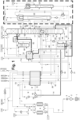
- the cleaned high-pressure feed air flow 7 is divided into a total of three partial flows 71, 72, 73 and introduced into a main heat exchanger 8.
- the first partial flow 71 is first passed through line 9 and the after-compressor 10 with after-cooler 11 and is thereby recompressed to a fourth pressure level, which in the example is 1.5 times higher than the third pressure level.
- the recompressed first partial flow 71 is Main heat exchanger cooled only to an intermediate temperature and then fed via line 12 to a work-performing expansion in a turbine 13. (The turbine 13 drives the secondary compressor 10 via a common shaft.)
- the feed air stream 14, which has been work-performingly expanded to about 5.5 bar, has a liquid content of about 11.5 mol%.
- the medium-pressure column is introduced completely into the medium-pressure column 15, directly into its bottom area.
- This column is part of a distillation system (10) for nitrogen-oxygen separation, which also has a condenser-evaporator 16, usually referred to as the main condenser, and a low-pressure column 17.
- the medium-pressure column is operated under a pressure of 5.5 bar, the low-pressure column under 1.4 bar ("first" and "second pressure level").
- a second part 72 of the high-pressure feed air stream is introduced into the main heat exchanger 8 as a so-called throttle stream under the third pressure level and is cooled there to the cold end. It is then expanded in a throttle valve 18 to just above the medium-pressure column pressure.
- a Joule-Thomson turbine can also be used instead of a throttle valve.
- the throttle stream which is now at least partially liquid, is fed via line 19 into the medium-pressure column, namely at a "second intermediate point" which is, for example, 3 to 12, preferably 5 to 8 theoretical plates above the bottom.
- a third part 73 of the high-pressure feed air flow forms a second throttle flow. Before it is fed into the main heat exchanger, it is recompressed together with the first part 71, but is then cooled in the main heat exchanger under the particularly high pressure to the cold end, where it is expanded in a similar way to the other throttle flow 72 and is led together with it via line 19 in a predominantly liquid state to the "second intermediate point".
- the distillation system for nitrogen-oxygen separation with the two columns 15, 17, the main condenser 16 functions together with the countercurrent subcooling device 21 as is known and therefore does not need to be described in detail here, as does the argon system 24 with the crude argon column 22 and the pure argon column 23.
- liquid nitrogen "LIN Inj.” can also be introduced into the distillation system from the outside as a cold source (liquid injection).
- the product of the argon system 24 is liquid pure argon LAR.
- residual streams can be vented into the atmosphere (ATM, GOX venting).
- krypton and xenon are also separated in a Kr-Xe enrichment column 40.
- liquid oxygen 41 is taken from the bottom of the low-pressure column 17 (or from the evaporation space of the main condenser 16), freed from impurities such as dinitrogen monoxide in a liquid adsorber and fed into the column 40 via line 43.
- Part of the krypton- and xenon-free liquid oxygen 45 is used as reflux liquid; this is withdrawn from the low-pressure column above some barrier plates 46 and the rest is mainly or completely fed to the internal compression (pump 31).
- helium and neon are also enriched to a He-Ne concentrate (crude He/Ne) in an additional column 60, which is connected in the known manner.
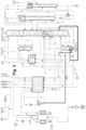
- Figure 2 corresponds in large parts Figure 1
- Figure 1 Deviating from Figure 1
- the liquid 149 produced in the bottom evaporator 47 (the intermediate fraction downstream of the bottom evaporator) is introduced into the medium-pressure column at a third intermediate point, which in the example is located about 3 to 10 theoretical plates above the first intermediate point.
- liquid 149 can also be mixed with the remaining liquid air in line 19 and fed together with it into the medium pressure column, as described in Figure 3 is shown.
Landscapes
- Engineering & Computer Science (AREA)
- Physics & Mathematics (AREA)
- Mechanical Engineering (AREA)
- Thermal Sciences (AREA)
- General Engineering & Computer Science (AREA)
- Health & Medical Sciences (AREA)
- Emergency Medicine (AREA)
- Separation By Low-Temperature Treatments (AREA)
Abstract
Bei dem Verfahren der Erfindung handelt es sich um einen Hochdruckprozess zur Tieftemperaturzerlegung von Luft unter Verwendung einer Luftzerlegungsanlage, die ein Destillationssystem zur Stickstoff-Sauerstofftrennung mit einer Mitteldruckkolonne (15) und einer Niederdruckkolonne (17) und außerdem eine Kr-Xe-Anreicherungskolonne (40). Ein erster Teil (71, 13) des Hochdruckeinsatzluftstroms (7) wird arbeitsleistend entspannt (13) und in die Mitteldruckkolonne (15) eingeleitet. Der Sumpfverdampfer (47) der Anreicherungskolonne (40) wird mit einer Zwischenfraktion (48) beheizt, die gasförmig aus der der Mitteldruckkolonne (15) entnommen wird.
Description
- Die Erfindung betrifft ein Verfahren und eine Vorrichtung gemäß den Oberbegriffen der unabhängigen Patentansprüche.
- Die Herstellung von Luftprodukten in flüssigem oder gasförmigem Zustand durch Tieftemperaturzerlegung von Luft in Luftzerlegungsanlagen ist bekannt und beispielsweise bei H.-W. Häring (Hrsg.), Industrial Gases Processing, Wiley-VCH, 2006, insbesondere Abschnitt 2.2.5, "Cryogenic Rectification", beschrieben. Sofern nicht ausdrücklich abweichend definiert, besitzen die nachfolgend verwendeten Begriffe den in der Fachliteratur üblichen Bedeutungsgehalt.
- Zur Luftzerlegung können bekanntermaßen sogenannte Haupt(luft)verdichter/Nachverdichter-Verfahren (Main Air Compressor/Booster Air Compressor, MAC/BAC) oder sogenannte Hochluftdruck-Verfahren (High Air Pressure, HAP) eingesetzt werden. Bei den Hauptluftverdichter/Nachverdichter-Verfahren handelt es sich um die eher konventionelleren Verfahren, Hochluftdruck-Verfahren kommen zunehmend in jüngerer Zeit als Alternativen zum Einsatz. Auf die weiteren Erläuterungen unten wird verwiesen. Abhängig von der Produktkonfiguration weisen Hochluftdruck-Verfahren generell bestimmte Vorteile auf, insbesondere eine relativ geringe Anzahl an drehenden Maschinen und damit geringeren Baukosten. Bei der Erfindung handelt es sich in der Regel um ein Zweisäulenverfahren zur Luftzerlegung, gegebenenfalls mit angeschlossener Argonsäule. Solche Prozesse werden üblicherweise mit möglichst niedrigem Druck in der Einsatzluft betrieben, das heißt die Gesamtluft wird lediglich auf etwa Mitteldruckkolonnendruck (das erste Druckniveau) verdichtet. Abweichend davon wird bei dem HAP-Verfahren der Erfindung die Gesamtluft auf einen Druck verdichtet, der mindestens 4 bar oberhalb des Druckniveaus der Mitteldruckkolonne liegt. (Alle Kolonnendrücke beziehen sich auf den Kopf der Kolonne, sofern im Folgenden nichts Anderes gesagt ist.)
- Die Aufgabe der Erfindung besteht darin, auch Krypton und Xenon aus der Einsatzluft auszuschleusen.
- Diese Aufgabe wird durch die kennzeichnenden Merkmale der unabhängigen Patentansprüche gelöst.
- Allgemeines Fachwissen zur Gewinnung eines Krypton-Xenon-Konzentrats ist ebenfalls der Monografie von Häring, Industrial Gases Processing, Wiley-VCH, 2006 zu entnehmen, nämlich dem Abschnitt 3.3 "Recovery of Krypton and Xenon". Dazu ist es üblich, aus einer Niederdruckkolonne eine flüssige Sauerstofffraktion zu entnehmen und einer luftbeheizten Kr-Xe-Anreicherungskolonne zuzuleiten, an deren Sumpf ein Kr-Xe-Konzentrat entnommen wird. Dieses Konzentrat wird üblicherweise am Ort der Luftzerlegungsanlage in einem Tank gesammelt und von Zeit zu Zeit zu einer Aufbereitungsanlage transportiert, in der reines Krypton und reines Xenon produziert werden. Grundsätzlich kann die Aufarbeitung auch am Ort der Luftzerlegungsanlage erfolgen, zum Beispiel, wenn Kr-Xe-Konzentrate auf weiteren, eventuell benachbarten Luftzerlegungsanlagen zur Verfügung steht. Grundsätzlich könnte man diese Art der Krypton-Xenon-Gewinnung auch an einer HAP-Anlage durchführen, das heißt die Kr-Xe-Kolonne mit einem Luftstrom ausheizen. Allerdings steht bei einem HAP-System oftmals kein rein gasförmiger Luftstrom zur Verfügung, weil auch die Turbinenluft, die in den Sumpf der Mitteldruckkolonne geführt wird, bereits eine gewisse Menge, zum Beispiel 5 mol-% oder mehr, Flüssigkeit enthält. Dies macht den Anschluss einer üblichen Krypton-Xenon-Anreicherung an eine HAP-Anlage ineffizient und führt zu Schwierigkeiten bei der Regelung des Sumpfverdampfers der Kr-Xe-Anreicherungssäule. Bislang wurde bei HAP-Prozessen (genauso wie MAC-BAC-Prozessen) als Heizmedium des Kr-Xe-Aufkochers die hauptsächlich gasförmige Luft des Einsatzes der Mitteldruckkolonne verwendet. Dies ist jedoch a) energetisch nicht optimal und kann b) zu Betriebsproblemen in der Regelung des Kr-Xe-Aufkochers führen.
- Im Rahmen der Erfindung hat sich überraschenderweise herausgestellt, dass die Verwendung einer gasförmigen Zwischenfraktion aus der Mitteldruckkolonne, die einen moderaten Sauerstoffgehalt aufweist, nicht nur die oben geschilderten Probleme vermeidet, sondern sogar zu einer Energieeinsparung von etwa 1 % für die Gesamtanlage durch Verbesserung der Sauerstoff-Produktausbeute führt; auch wird die Belastung des Sauerstoffabschnitts der Niederdrucksäule verringert. Außerdem treten mangels eines zweiphasigen Heizmediums keine besonderen Probleme bei der Regelung des Kr-Xe-Sumpfverdampfers auf. Ferner kann die Kr-Xe-Anreicherungskolonne auf einer geodätisch höheren Position angeordnet werden, was die Einleitung des kondensierten Heizmediums in die Niederdruckkolonne einfacher macht. Insgesamt ergibt sich damit ein HAP-Verfahren, in dem auf wirtschaftliche Weise auch Krypton und Xenon abgetrennt werden können.
- Ausgestaltungen der Erfindung sind Gegenstand der abhängigen Patentansprüche und der nachfolgenden Beschreibung.
- Es werden zunächst weitere Grundlagen der Erfindung näher erläutert und zur Beschreibung der Erfindung verwendete Begriffe definiert.
- So soll sich der Begriff Luftprodukt hier insbesondere auf ein Fluid beziehen, das zumindest teilweise durch Tieftemperaturzerlegung von atmosphärischer Luft bereitgestellt wird. Ein Luftprodukt gemäß dem hier zugrundeliegenden Verständnis weist ein oder mehrere in der atmosphärischen Luft enthaltene Luftgase in einer abweichenden Zusammensetzung als in der atmosphärischen Luft auf. Ein Luftprodukt kann grundsätzlich in gasförmigem, flüssigem oder überkritischem Zustand vorliegen oder bereitgestellt werden und von einem dieser Aggregatzustände in einen anderen überführt werden. Insbesondere kann ein flüssiges Luftprodukt durch Erwärmen auf einem bestimmten Druck in den gasförmigen Zustand überführt (verdampft) oder in den überkritischen Zustand überführt (pseudoverdampft) werden, je nachdem, ob der Druck bei der Erwärmung unterhalb oder oberhalb des kritischen Drucks liegt. Ist nachfolgend von einem "Verdampfen" die Rede, soll dies auch eine entsprechende Pseudoverdampfung einschließen.
- Luftzerlegungsanlagen weisen Rektifikationskolonnenanordnungen auf, die unterschiedlich ausgestaltet sein können. Neben Rektifikationskolonnen (Destillationssystemen) zur Gewinnung von Stickstoff und/oder Sauerstoff in flüssigem und/oder gasförmigem Zustand, also Rektifikationskolonnen zur Stickstoff-SauerstoffTrennung, die insbesondere in einer bekannten Doppelkolonne zusammengefasst sein können, können Rektifikationskolonnen zur Gewinnung weiterer Luftkomponenten, insbesondere von Edelgasen, oder von Reinsauerstoff vorgesehen sein.
- Die Rektifikationskolonnen typischer Rektifikationskolonnenanordnungen werden auf unterschiedlichen Druckniveaus betrieben. Bekannte Doppelkolonnen weisen eine sogenannte Mitteldruckkolonne (auch als Hochdruckkolonne, Druckkolonne oder untere Kolonne bezeichnet) und eine sogenannte Niederdruckkolonne (obere Kolonne) auf. Die Hochdruckkolonne wird typischerweise in einem Druckbereich von 4 bis 7 bar, insbesondere auf ca. 5,3 bar, betrieben, die Niederdruckkolonne dagegen in einem Druckbereich von typischerweise 1 bis 2 bar, insbesondere bei ca. 1,4 bar.
- In Luftzerlegungsanlagen kommen zur Verdichtung der Einsatzluftmenge mehrstufige Turboverdichter zum Einsatz, die hier als Hauptluftverdichter bezeichnet werden. Der mechanische Aufbau von Turboverdichtern ist dem Fachmann grundsätzlich bekannt. In einem Turboverdichter erfolgt die Verdichtung des zu verdichtenden Mediums mittels Turbinenschaufeln, die auf einem Turbinenrad oder direkt auf einer Welle angeordnet sind. Ein Turboverdichter bildet dabei eine bauliche Einheit, die jedoch bei einem mehrstufigen Turboverdichter mehrere Verdichterstufen aufweisen kann. Eine Verdichterstufe umfasst dabei in der Regel ein Turbinenrad oder eine entsprechende Anordnung von Turbinenschaufeln. Alle dieser Verdichterstufen können von einer gemeinsamen Welle angetrieben werden. Es kann jedoch auch vorgesehen sein, die Verdichterstufen gruppenweise mit unterschiedlichen Wellen anzutreiben, wobei die Wellen auch über Getriebe miteinander verbunden sein können.
- Der Hauptluftverdichter zeichnet sich ferner dadurch aus, dass durch diesen die gesamte in die Rektifikationskolonnenanordnung eingespeiste und zur Herstellung von Luftprodukten verwendete Luftmenge, also die gesamte Einsatzluftmenge, verdichtet wird. Entsprechend kann auch ein Nachverdichter vorgesehen sein, in dem aber nur ein Teil der im Hauptluftverdichter verdichteten Einsatzluftmenge auf einen nochmals höheren Druck gebracht wird. Auch dieser kann als Turboverdichter ausgebildet sein. Zur Verdichtung von Teilluftmengen sind typischerweise weitere Turboverdichter vorgesehen, die auch als Booster bezeichnet werden, im Vergleich zu dem Hauptluftverdichter oder dem Nachverdichter jedoch typischerweise nur eine Verdichtung in relativ geringem Umfang, insbesondere bezogen auf die verdichtete Luftmenge, vornehmen. Auch in einem Hochluftdruck-Verfahren (s.u.) kann ein Nachverdichter vorhanden sein, dieser verdichtet jedoch eine Teilmenge der Einsatzluftmenge dann ausgehend von einem höheren Druck. Der Nachverdichter kann im Warmen oder auch als Kaltverdichter betrieben werden.
- Unter einem Kaltverdichter bzw. Kaltbooster soll hier ein Verdichter bzw. Booster verstanden werden, dem Fluid auf einer Temperatur in einem Temperaturbereich deutlich unterhalb der Umgebungstemperatur der Luftzerlegungsanlage, insbesondere bei einer Temperatur von weniger als -50 °C oder -100 °C und insbesondere mehr als -150 °C oder -200 °C zugeführt wird. Einem Warmverdichter bzw. Warmbooster wird dagegen Fluid auf einer Temperatur in einem Temperaturbereich von mehr als -30 °C, 0 °C, 20 °C oder 50 °C und insbesondere bis zu 100 °C oder 200 °C zugeführt.
- An mehreren Stellen in Luftzerlegungsanlagen kann ferner Luft entspannt werden, wozu unter anderem Entspannungsmaschinen in Form von Turboexpandern, hier auch als Entspannungsturbinen oder kurz Turbinen bezeichnet, zum Einsatz kommen können. Turboexpander können auch mit Turboverdichtern gekoppelt sein und diese antreiben. Werden ein oder mehrere Turboverdichter ohne extern zugeführte Energie, d.h. nur über einen oder mehrere Turboexpander, angetrieben, wird für eine derartige Anordnung auch der Begriff Turbinenbooster verwendet. In einem Turbinenbooster sind der Turboexpander (die Entspannungsturbine) und der Turboverdichter (der Booster) mechanisch gekoppelt, wobei die Kopplung drehzahlgleich (beispielsweise über eine gemeinsame Welle) oder drehzahlunterschiedlich (beispielsweise über ein zwischengeschaltetes Getriebe) erfolgen kann. Ist hier von einer Turbineneinheit die Rede, soll hierunter insbesondere eine Anordnung mit wenigstens einer Entspannungsturbine verstanden werden.
- Hauptluftverdichter/Nachverdichter-Verfahren zeichnen sich dadurch aus, dass nur ein Teil der der Rektifikationskolonnenanordnung insgesamt zugeführten Einsatzluftmenge auf ein Druckniveau verdichtet wird, das wesentlich, d.h. um mindestens 3, 4, 5, 6, 7, 8, 9 oder 10 bar, oberhalb des Druckniveaus der Druckkolonne, und damit über dem höchsten in der Rektifikationskolonnenanordnung verwendeten Druckniveau, liegt. Ein weiterer Teil der Einsatzluftmenge wird lediglich auf das Druckniveau der Druckkolonne oder höchstens auf ein Druckniveau, das sich um nicht mehr als 1 bis 2 bar hiervon unterscheidet, verdichtet, und auf diesem ohne Entspannung in die Druckkolonne eingespeist. Ein Beispiel für ein derartiges Hauptluftverdichter/Nachverdichter-Verfahren ist bei Häring (s.o.) in Figur 2.3A gezeigt.
- Bei einem Hochluftdruck-Verfahren wird hingegen typischerweise die gesamte der Rektifikationskolonnenanordnung insgesamt zugeführte Einsatzluftmenge auf ein Druckniveau verdichtet, das wesentlich, d.h. um 3, 4, 5, 6, 7, 8, 9 oder 10 bar oder mehr oberhalb des Druckniveaus der Druckkolonne und damit über dem höchsten in der Rektifikationskolonnenanordnung verwendeten Druckniveau, liegt. Der Druckunterschied kann beispielsweise bis zu 14, 16, 18 oder 20 bar oder mehr betragen. Hochluftdruck-Verfahren sind vielfach beschrieben worden und beispielsweise aus der
EP 2 980 514 A1 und derEP 2 963 367 A1 bekannt. - Hochluftdruck-Verfahren kommen typischerweise mit der sogenannten Innenverdichtung (IV, Internal Compression, IC) zum Einsatz. Bei der Innenverdichtung wird wenigstens ein gasförmiges, druckbeaufschlagtes Luftprodukt, das mittels der Luftzerlegungsanlage bereitgestellt wird, dadurch gebildet, dass der Rektifikationskolonnenanordnung ein tiefkaltes, flüssiges Luftprodukt entnommen, einer Druckerhöhung auf einen Produktdruck unterworfen, und auf dem Produktdruck durch Erwärmen in den gasförmigen oder überkritischen Zustand überführt wird. Beispielsweise können mittels Innenverdichtung gasförmiger, druckbeaufschlagter Sauerstoff (GOX IV, GOX IC) gasförmiger, druckbeaufschlagter Stickstoff (GAN IV, GAN IC) und/oder gasförmiges, druckbeaufschlagtes Argon (GAR IV, GAR IC) erzeugt werden. Die Innenverdichtung bietet eine Reihe von Vorteilen gegenüber einer alternativ ebenfalls möglichen externen Verdichtung und ist z.B. bei Häring (s.o.) in Abschnitt 2.2.5.2, "Internal Compression", erläutert.
- In typischen Luftzerlegungsanlagen sind zur Kälteerzeugung und Verflüssigung von Stoffströmen an unterschiedlichen Stellen entsprechende Entspannungsturbinen vorhanden. Hierbei handelt es sich insbesondere um Claude-Turbinen und Lachmann-Turbinen sowie ggf. um Joule-Thomson-Turbinen. Zur Funktion und zum Zweck entsprechender Turbinen wird auf die Fachliteratur, beispielsweise F.G. Kerry, Industrial Gas Handbook: Gas Separation and Purification, CRC Press, 2006, insbesondere die Abschnitte 2.4, "Contemporary Liquefaction Cycles", 2.6, "Theoretical Analysis of the Claude Cycle" und 3.8.1, "The Lachmann Principle", verwiesen.
- Bekannt sind insbesondere Hochluftdruck-Verfahren, in denen die erwähnten Lachmann-Turbinen eingesetzt werden. Die in einer Lachmannturbine entspannte Luft wird in die Niederdruckkolonne eingespeist (eingeblasen), weshalb diese auch als Einblaseturbine (engl. auch Upper Column Expander) bezeichnet wird. Die Lachmannturbine kann dabei als weitere Turbineneinheit neben einer Turbineneinheit, mittels derer gasförmige Druckluft in die Druckkolonne entspannt wird, also einer Claude-Turbine, bereitgestellt sein.
- Der Begriff der eingeblasenen Luftmenge bezieht sich auf die mit einer typischen Lachmann-Turbine (Einblaseturbine) entspannte und in die Niederdruckkolonne eingespeiste (eingeblasene) Druckluft. Die auf diese Weise in die Niederdruckkolonne entspannte Luft stört die Rektifikation, weshalb die Menge der in der Einblaseturbine entspannbaren Luft und damit die für eine entsprechende Anlage auf diese Weise erzeugbare Kälte begrenzt sind. Auch stickstoffreiche Luftprodukte, die der Druckkolonne als Druckstickstoff entnommen und aus der Luftzerlegungsanlage ausgeführt werden, und auch aus der Luftzerlegungsanlage ausgeführter Flüssigstickstoff sowie aus der Luftzerlegungsanlage ausgeführter innenverdichteter Stickstoff beeinflussen die Rektifikation entsprechend und/oder und weisen gemeinsame Effekte auf.
- Die Menge der in die Niederdruckkolonne mittels einer Lachmann-Turbine eingeblasenen Luft zuzüglich des der Druckkolonne entnommenen und aus der Luftzerlegungsanlage ausgeführten Stickstoffs sowie zuzüglich des aus der Luftzerlegungsanlage ausgeführten Flüssigstickstoffs sowie zuzüglich des aus der Luftzerlegungsanlage ausgeführten innenverdichteten Stickstoffs (soweit jeweils vorhanden) kann im Verhältnis zur gesamten, der Rektifikationskolonnenanordnung zugeführten Luftmenge angegeben werden. Der auf diese Weise erhaltene Wert wird als Einblaseäquivalent bezeichnet.
- Unter einem Drosselstrom oder Joule-Thomson-Strom wird eine Luftmenge verstanden, die im Hauptwärmetauscher einer Luftzerlegungsanlage zumindest zum überwiegenden Anteil unter Druck verflüssigt und danach, insbesondere über ein Drosselventil, insbesondere in die Druckkolonne eingespeist wird. Anstelle eines Drosselventils kann auch eine Joule-Thomson-Turbine eingesetzt werden. Wenn der Drosselstrom überkritisch ist, tritt die Verflüssigung erst bei der Entspannung ein.
- Flüssige, gasförmige oder auch im überkritischen Zustand vorliegende Fluide können im hier verwendeten Sprachgebrauch reich oder arm an einer oder mehreren Komponenten sein, wobei "reich" für einen Gehalt von wenigstens 75%, 90%, 95%, 99%, 99,5%, 99,9% oder 99,99% und "arm" für einen Gehalt von höchstens 25%, 10%, 5%, 1%, 0,1% oder 0,01% auf Mol-, Gewichts- oder Volumenbasis stehen kann. Der Begriff "überwiegend" kann der soeben getroffenen Definition von "reich" entsprechen, bezeichnet jedoch insbesondere einen Gehalt von mehr als 90%. Ist hier beispielsweise von "Stickstoff" die Rede, kann es sich um ein Reingas, aber auch ein an Stickstoff reiches Gas handeln.
- Hochluftdruck-Verfahren können in unterschiedlichen Ausgestaltungen eingesetzt werden. Diese werden oft nach Flüssigleistung der Anlage, d.h. nach der Menge an flüssig bereitgestellten und flüssig der Anlage entnommenen Luftprodukten (hier auch als Flüssigprodukte bezeichnet), bzw. nach dem Verhältnis von innenverdichteten Luftprodukten zu Flüssigprodukten klassifiziert und unterschieden.
- Die Zwischenfraktion, die als Heizmittel für die Kr-Xe-Anreicherungskolonne verwendet wird, weist vorzugsweise einen Sauerstoffgehalt von 4 bis 15 mol-%, insbesondere von 6 bis 10 mol-% auf. Dies führt zu einer optimalen Temperaturdifferenz in dem Sumpfverdampfer, der regelmäßig als Kondensatorverdampfer ausgebildet ist.
- Bei der Erfindung ist es günstig, wenn ein Teil des Hochdruckeinsatzluftstroms im Hauptwärmetauscher bis zu dessen kaltem Ende abgekühlt, auf einen Druck im ersten Druckbereich entspannt und anschließend wenigstens teilweise flüssig an einer zweiten Zwischenstelle in die Mitteldruckkolonne eingeleitet wird. Dieser Strom kann insbesondere den Drosselstrom für eine Innenverdichtung darstellen. Der Turbinenstrom, welcher der arbeitsleistenden Entspannung auf Mitteldrucksäulendruck zugeführt wird, wird vorher lediglich auf eine Zwischentemperatur von beispielweise 115 bis 140 K abgekühlt; nach der arbeitsleistenden Entspannung weist er eine Temperatur von beispielsweise 96 bis 105 K auf. Ein Teil, der an der zweiten Zwischenstelle eingespeisten Flüssigkeit kann an der zweiten Zwischenstelle (unmittelbar unterhalb der Zuspeisung) wieder entnommen und in die Niederdrucksäule an einer ersten Niederdrucksäulenzwischenstelle eingeleitet werden.
- Es kann ferner vorteilhaft sein, wenn zwischen der ersten Zwischenstelle, an der die Zwischenfraktion aus der Mitteldruckkolonne entnommen wird und der zweiten Zwischenstelle kein Stoffaustauschabschnitt oder ein Stoffaustauschabschnitt von weniger als 15, insbesondere weniger als 10 theoretischen Böden liegt.
- Die Zwischenfraktion wird in dem Sumpfverdampfer der Kr-Xe-Anreicherungskolonne teilweise oder vollständig verflüssigt, das heißt der Sumpfverdampfer ist als Kondensatorverdampfer ausgebildet. Die dabei gebildete Flüssigkeit kann an jeder geeigneten Stelle des Destillationssystems eingespeist werden, insbesondere in die Mitteldruckkolonne oder die Niederdruckkolonne. Auch eine Aufteilung zwischen den beiden Kolonnen ist möglich. Eine Einleitung in die Mitteldruckkolonne kann auch gemeinsam mit anderen Flüssigluftströmen erfolgen.
- In einer ersten Variante wird mindestens ein Teil der Zwischenfraktion stromabwärts des Verdampfers in die Niederdrucksäule eingeleitet. Insbesondere kann der in die Niederdruckkolonne eingeleitete Teil der Zwischenfraktion an einer zweiten Niederdrucksäulenzwischenstelle eingespeist werden. Dabei ist zwischen der ersten und der zweiten Niederdrucksäulenzwischenstelle ein Stoffaustauschabschnitt 53 angeordnet, der mindestens 4 theoretische Böden umfasst. Diese Maßnahme verbessert die Destillationsleistung der Niederdruckkolonne weiter.
- Alternativ oder zusätzlich wird mindestens ein Teil der Zwischenfraktion stromabwärts des Verdampfers in die Mitteldrucksäule eingeleitet, insbesondere an einer dritten Zwischenstelle, die mindestens 3 theoretische Böden oberhalb der ersten Zwischenstelle liegt. Diese Maßnahme verbessert die Destillationsleistung der Mitteldruckkolonne weiter. Der erste Teil des entspannten Einsatzluftstroms wird insbesondere der Mitteldruckkolonne am Sumpf zugeleitet
- Der entspannte Einsatzluftstrom weist vorteilhafterweise einen Flüssiganteil von 2 bis 20 mol-%, insbesondere von 8 bis 13 mol-% auf.
- Ähnlich wie andere HAP-Verfahren ist auch der Prozess der Erfindung für die Erzeugung von Sauerstoff- und Stickstoffgasprodukten unter erhöhtem Druck durch die Methode der Innenverdichtung geeignet. Hierzu wird eine zweite flüssige Sauerstofffraktion aus der Niederdruckkolonne entnommen, mittels einer Pumpe auf einen ersten Produkthochdruck gebracht, im Hauptwärmetauscher angewärmt und schließlich als gasförmiges Drucksauerstoffprodukt (GOX-IC1) gewonnen. Alternativ oder zusätzlich wird ein flüssiger Stickstoffstrom aus der Niederdruckkolonne entnommen, mittels einer Pumpe auf einen zweiten Produkthochdruck gebracht, im Hauptwärmetauscher angewärmt und schließlich als gasförmiges Druckstickstoffprodukt (HP-GAN) gewonnen.
- Der erste Teil des Hochdruckeinsatzluftstroms kann stromaufwärts der arbeitsleistenden Entspannung in einem Nachverdichter weiter verdichtet werden, wobei der Nachverdichter insbesondere von einer Turbine angetrieben wird, in der die arbeitsleistende Entspannung durchgeführt wird. Der Nachverdichter kann grundsätzlich
- die gesamte Einsatzluft
- nur die Turbinenluft (den ersten Teil des Hochdruckeinsatzluftstroms) oder auch
- die Turbinenluft plus einen zweiten Drosselstrom, der unter weiter erhöhtem Druck in den Hauptwärmetauscher eingeleitet wird,
- Das Verfahren der Erfindung kann als Ein-Turbinen-Verfahren ausgebildet sein. Alternativ werden zwei Turbinen eingesetzt, die unabhängig von einander von dem dritten oder vierten Druck oder einem weiteren Druckbereich auf knapp über den Druck der Mitteldruckkolonne entspannen und verschiedene Ein- und Austrittstemperaturen aufweisen. Alternativ werden zwei Turbinen eingesetzt, die parallel zu einander geschaltet sind und die gleiche Austrittstemperatur ausweisen. Der erste Teil des Hochdruckeinsatzluftstroms wird dann auf die beiden Turbinen aufgeteilt und nach der arbeitsleistenden Entspannung wieder vereinigt, um den entspannten Einsatzluftstrom zu bilden. Die beiden einzelnen Ströme können nach der arbeitsleistenden Entspannung unterschiedliche Flüssiggehalte aufweisen. In der Summe ergibt sich im Allgemeinen ein Flüssiganteil, der im selben Zahlenbereich liegt wie bei einer einzigen Turbine.
- In einer weiteren Ausführung kann auch eine der Turbinen als eine sogenannte Lachmann-Turbine ausgeführt werden, wobei diese Turbine die Luft auf einen Druck leicht oberhalb der Niederdruckkolonne entspannt und der Niederdruckkolonne zuführt.
- Es kann bei dem Verfahren der Erfindung günstig sein, wenn mindestens ein Teil der Zwischenfraktion stromabwärts des Verdampfers vor seiner Einleitung in die Niederdrucksäule abgekühlt wird. Die Abkühlung kann in einem üblichen Unterkühlungsgegenströmer durchgeführt werden in indirektem Wärmeaustausch mit einem oder mehreren kalten Gasströmen aus der Niederdruckkolonne.
- Die Erfindung betrifft außerdem eine entsprechende Vorrichtung zur Tieftemperaturzerlegung von Luft. Diese Vorrichtung kann durch weitere Vorrichtungsmerkmale ergänzt werden, die den Verfahrensmerkmalen der abhängigen Ansprüche entsprechen.
- Die Erfindung sowie weitere Einzelheiten der Erfindung werden im Folgenden anhand von in den Zeichnungen schematisch dargestellten Ausführungsbeispielen näher erläutert. Hierbei zeigen:
- Figur 1
- ein erstes Ausführungsbeispiel der Erfindung mit Einleitung der flüssigen Zwischenfraktion in die Niederdrucksäule,
- Figur 2
- ein zweites Ausführungsbeispiel der Erfindung mit Einleitung der flüssigen Zwischenfraktion in die Mitteldrucksäule und
- Figur 3
- ein drittes Ausführungsbeispiel der Erfindung mit Einleitung der flüssigen Zwischenfraktion in die Mitteldrucksäule an einer anderen Stelle.
- In der Luftzerlegungsanlage der
Figur 1 wird Luft (AIR) mittels eines Hauptluftverdichters 2 über ein Filter 1 angesaugt und auf ein "drittes Druckniveau" verdichtet, das in dem Beispiel bei 12 bis 24 bar liegt. Der auf diese Weise gebildete Hochdruckeinsatzluftstrom 4, 5, 7 wird nach Vorkühlung in einer Vorkühleinrichtung 3 in eine Vorreinigungseinheit 4 geführt, die in an sich bekannter Art ausgestaltet sein kann. Dort wird sie von Restwasser und Kohlendioxid befreit. Zur Ausgestaltung der angesprochenen Komponenten sei, auf die eingangs zitierte Fachliteratur verwiesen. - Der gereinigte Hochdruckeinsatzluftstrom 7 wird in insgesamt drei Teilströme 71, 72, 73 aufgeteilt in einem Hauptwärmetauscher 8 eingeleitet. Der erste Teilstrom 71 wird vorher über Leitung 9 und den Nachverdichter 10 mit Nachkühler 11 geleitet und dabei auf ein viertes Druckniveau nachverdichtet, das in dem Beispiel um den Faktor 1,5 höher liegt als das dritte Druckniveau. Der nachverdichtete erste Teilstrom 71 wird im Hauptwärmetauscher nur auf eine Zwischentemperatur abgekühlt und dann über Leitung 12 einer arbeitsleistenden Entspannung in einer Turbine 13 zugeführt. (Die Turbine 13 treibt über eine gemeinsame Welle den Nachverdichter 10 an.) Der auf etwa 5,5 bar arbeitsleistend entspannte Einsatzluftstrom 14 weist einen Flüssiganteil von etwa 11,5 mol-% auf. Er wird in diesem Beispiel vollständig in die Mitteldruckkolonne 15 eingeführt, unmittelbar in deren Sumpfbereich. Diese Kolonne ist Teil eines Destillationssystems (10) zur Stickstoff-Sauerstofftrennung, das außerdem einen üblicherweise als Hauptkondensator bezeichneten Kondensatorverdampfer 16 und eine Niederdruckkolonne 17 aufweist. In dem Beispiel wird die Mitteldruckkolonne unter einem Druck von 5,5 bar betrieben, die Niederdruckkolonne unter 1,4 bar ("erstes" und "zweites Druckniveau").
- Ein zweiter Teil 72 der Hochdruckeinsatzluftstroms wird als so genannter Drosselstrom unter dem dritten Druckniveau in den Hauptwärmetauscher 8 eingeführt und dort bis zum kalten Ende abgekühlt. Anschließend wird er in einem Drosselventil 18 auf knapp über Mitteldrucksäulendruck entspannt. Anstelle eines Drosselventils kann auch eine Joule-Thomson-Turbine eingesetzt werden. Der nun mindestens teilweise flüssig vorliegende Drosselstrom wird über Leitung 19 in die Mitteldruckkolonne geleitet, und zwar an einer "zweiten Zwischenstelle", die beispielsweise 3 bis 12 vorzugsweise 5 bis 8 theoretische Böden oberhalb des Sumpfs liegt.
- Ein dritter Teil 73 des Hochdruckeinsatzluftstroms bildet einen zweiten Drosselstrom. Er wird vor seiner Einspeisung in den Hauptwärmetauscher gemeinsam mit dem ersten Teil 71 nachverdichtet, dann aber im Hauptwärmetauscher unter dem besonders hohen Druck bis zum kalten Ende abgekühlt, dort analog zum anderen Drosselstrom 72 entspannt und zusammen mit diesem über Leitung 19 in überwiegend flüssigem Zustand zur "zweiten Zwischenstelle" geführt.
- Das Destillationssystem zur Stickstoff-Sauerstofftrennung mit den beiden Kolonnen 15, 17, dem Hauptkondensator 16 funktioniert zusammen mit dem Unterkühlungsgegenströmer 21 wie bekannt und braucht deshalb hier nicht im Detail beschrieben zu werden, ebenso wie das Argonsystem 24 mit der Rohargonkolonne 22 und der Reinargonkolonne 23.
- Die Sumpfflüssigkeit aus der Mitteldruckkolonne wird in dem Beispiel indirekt in die Niederdruckkolonne geleitet, nachdem sie zum Heizen und Kühlen des Sumpfverdampfers und der Kopfkondensatoren des Argonsystems 24 eingesetzt wurde. Sie strömt dabei über Leitung 25, durch den Unterkühlungsgegenströmer 21 und weiter über Leitung 26 in das Argonsystem 24 und von dort teilweise gasförmig über die Leitungen 27 und 29 und teilweise flüssig über die Leitungen 28 und 30 in die Niederdruckkolonne. Hauptprodukte der Anlage sind innenverdichteter Sauerstoff GOX-IC1 und innenverdichteter Stickstoff HP-GAN, die flüssig aus dem Destillationssystem abgezogen und mittels Pumpen 31, 32 auf den gewünschten Produktdruck gebracht werden. Außerdem können flüssiger Stickstoff LIN und flüssiger Sauerstoff LOX gewonnen werden. Umgekehrt kann auch flüssiger Stickstoff "LIN Inj." von außen als Kältequelle in das Destillationssystem eingeführt werden (Liquid Injection). Das Produkt des Argonsystems 24 ist flüssiges Reinargon LAR. An verschiedenen Stellen können Restströme in die die Atmosphäre abgeblasen werden (ATM, GOX Abblasung).
- Gemäß der Erfindung werden außerdem Krypton und Xenon in einer Kr-Xe-Anreicherungskolonne 40 abgetrennt. Hierzu wird flüssiger Sauerstoff 41 aus dem Sumpf der Niederdruckkolonne 17 (beziehungsweise aus dem Verdampfungsraum des Hauptkondensators 16) entnommen, in einem Flüssigadsorber von Verunreinigungen wie Distickstoffmonoxid befreit und über Leitung 43 in die Kolonne 40 eingespeist. Als Rücklaufflüssigkeit wird ein Teil des krypton- und xenonfreien flüssigen Sauerstoffs 45 verwendet; dieser wird oberhalb einiger Sperrböden 46 aus der Niederdruckkolonne abgezogen und im Übrigen hauptsächlich oder vollständig der Innenverdichtung (Pumpe 31) zugeführt. In der Kr-Xe-Anreicherungskolonne 40 wird der Krypton-Xenon-Gehalt von 1,1 ppm Krypton und 86 ppb Xenon im Einsatzstrom 43 auf 500 bis 5000 ppm Krypton und 40 bis 500 ppm Xenon erhöht. Entsprechend angereichertes Konzentrat (Crude Kr Xe) verlässt die Kolonne am Sumpf.
- Die Kolonne wird mit einem als Kondensatorverdampfer betriebenen Sumpfverdampfer 47 beheizt. Erfindungsgemäß wird dieser Sumpfverdampfer mit einer Zwischenfraktion 48 aus der Mitteldruckkolonne 15 beheizt. Die Zwischenfraktion 48 wird an einer "ersten Zwischenstelle" in Gasform entnommen und weist in dem Beispiel eine Sauerstoffkonzentration von etwa 8 mol-% auf. Die "erste Zwischenstelle" liegt bei dem Beispiel auf derselben Höhe wie die "zweite Zwischenstelle", das heißt zwischen den gleichen beiden Stoffaustauschabschnitten der Mitteldruckkolonne 15. Die Zwischenfraktion wird in dem Sumpfverdampfer mindestens teilweise verflüssigt; in dem Beispiel wird eine vollständige oder fast vollständige Verflüssigung durchgeführt. Die im Sumpfverdampfer 47 erzeugte Flüssigkeit 49 wird in dem Unterkühlungsgegenströmer 21 abgekühlt und in dem Beispiel der
Figur 1 über Leitung 50 in die Niederdruckkolonne eingeleitet. Die Einspeisestelle liegt 3 bis 10 theoretische Böden oberhalb der Stelle, an der mindestens ein Teil 51, 52 der flüssigen Luft aus der Innenverdichtung eingeleitet wird. - Bei dem Ausführungsbeispiel werden außerdem Helium und Neon zu einem He-Ne-Konzentrat (Crude He/Ne) angereichert in einer Zusatzkolonne 60, die auf die bekannte Weise verschaltet ist.
-
Figur 2 entspricht in weiten TeilenFigur 1 . Insofern wird auf die Beschreibung zuFigur 1 verwiesen. Abweichend vonFigur 1 wird hier die im Sumpfverdampfer 47 erzeugte Flüssigkeit 149 (die Zwischenfraktion stromabwärts des Sumpfverdampfers) in die Mitteldrucksäule eingeleitet, und zwar an einer dritten Zwischenstelle, die in dem Beispiel etwa 3 bis1 0 theoretische Böden oberhalb der ersten Zwischenstelle liegt. - Alternativ kann die Flüssigkeit 149 auch der übrigen Flüssigluft in Leitung 19 zugemischt werden und zusammen mit dieser in die Mitteldrucksäule eingespeist werden, wie es in
Figur 3 dargestellt ist. - Grundsätzlich können die Einleitung in die Niederdruckkolonne (
Figur 1 ) und in die Mitteldruckkolonne (Figur 2 und/oderFigur 3 ) auch kombiniert werden. Die Flüssigkeit 49, 149 aus dem Sumpfverdampfer 47 wird dann entsprechend aufgeteilt.
Claims (16)
- Verfahren zur Tieftemperaturzerlegung von Luft unter Verwendung einer Luftzerlegungsanlage, die ein Destillationssystem zur Stickstoff-Sauerstofftrennung mit einer Mitteldruckkolonne (15) und einer Niederdruckkolonne (17) aufweist, wobei- die Druckkolonne (11) in einem ersten Druckbereich und die Niederdruckkolonne (12) in einem zweiten Druckbereich, der unterhalb des ersten Druckbereichs liegt, betrieben werden, und- Einsatzluft in einem Hauptwärmetauscher (8) abgekühlt und dann in das Destillationssystem eingeleitet wird,- mindestens 90 % der gesamten in das Destillationssystem eingeleiteten Einsatzluft auf einen Druck in einem dritten Druckbereich verdichtet wird, der mehr als 4 bar oberhalb des ersten Druckbereichs liegt, um einen Hochdruckeinsatzluftstrom (7) zu bilden,- ein erster Teil (71, 13) des Hochdruckeinsatzluftstroms (7) arbeitsleistend entspannt (13) wird, um einen entspannten Einsatzluftstrom (14) zu bilden,- mindestens ein erster Teil des arbeitsleistend entspannten Einsatzluftstroms (14) in die Mitteldruckkolonne (15) eingeleitet wird,- Sumpfflüssigkeit aus der Mitteldruckkolonne (25) direkt oder indirekt in die Niederdruckkolonne (17) geleitet (27, 28, 29, 30) wird und- im Sumpf der Niederdruckkolonne eine erste flüssige Sauerstofffraktion (41) gewonnen wird,
dadurch gekennzeichnet, dass- mindestens ein Teil der ersten flüssigen Sauerstofffraktion (41) aus dem Sumpf der Niederdruckkolonne (17) in eine Kr-Xe-Anreicherungskolonne (40) eingeleitet wird,- dem Sumpf der Kr-Xe-Anreicherungskolonne (40) ein Kr-Xe-Konzentrat (Crude Kr Xe) entnommen wird,- die Anreicherungskolonne einen Sumpfverdampfer (47) aufweist, der mit einem Heizmedium betrieben wird,- der Mitteldruckkolonne (15) an einer ersten Zwischenstelle eine Zwischenfraktion (48) in Gasform entnommen wird und- die Zwischenfraktion als Heizmedium in dem Sumpfverdampfer (47) eingesetzt, dabei mindestens teilweise verflüssigt wird und anschließend in das Destillationssystem zur Stickstoff-Sauerstofftrennung eingeleitet (49, 50, 149) wird. - Verfahren nach Anspruch 1, bei dem die Zwischenfraktion (48) einen Sauerstoffgehalt von 4 bis 18 mol-%, insbesondere von 6 bis 10 mol-% aufweist.
- Verfahren nach Anspruch 1 oder 2, bei dem ein zweiter Teil (72) des Hochdruckeinsatzluftstroms (7) im Hauptwärmetauscher (8) bis zu dessen kaltem Ende abgekühlt, auf einen Druck im ersten Druckbereich entspannt (18) und anschließend wenigstens teilweise flüssig an einer zweiten Zwischenstelle in die Mitteldruckkolonne (15) eingeleitet (19) wird.
- Verfahren nach Anspruch 3, bei dem mindestens ein Teil 51 der an der zweiten Zwischenstelle eingespeisten Flüssigkeit an der zweiten Zwischenstelle wieder entnommen und in die Niederdrucksäule (17) an einer ersten Niederdrucksäulenzwischenstelle eingeleitet (52 wird.
- Verfahren nach Anspruch 3 oder 4, bei dem zwischen der ersten Zwischenstelle, an der die Zwischenfraktion (48) aus der Mitteldruckkolonne (15) entnommen wird, und der zweiten Zwischenstelle kein Stoffaustauschabschnitt oder ein Stoffaustauschabschnitt von weniger als 15 theoretischen Böden liegt.
- Verfahren nach einem der vorstehenden Ansprüche, bei dem mindestens ein Teil (49, 50) der Zwischenfraktion stromabwärts des Verdampfers (47) in die Niederdrucksäule (17) eingeleitet wird.
- Verfahren nach Anspruch 6, bei dem der in die Niederdruckkolonne (17) eingeleitete Teil der Zwischenfraktion (49, 50) an einer zweiten Niederdrucksäulenzwischenstelle eingespeist wird, wobei zwischen der ersten und der zweiten Niederdrucksäulenzwischenstelle ein Stoffaustauschabschnitt angeordnet ist, der mindestens 3 theoretische Böden umfasst.
- Verfahren nach einem der Ansprüche 1 bis 7, bei dem mindestens ein Teil der Zwischenfraktion (149) stromabwärts des Verdampfers (47) in die Mitteldrucksäule (15) eingeleitet wird, insbesondere an einer dritten Zwischenstelle, die mindestens 3 theoretische Böden oberhalb der ersten Zwischenstelle liegt.
- Verfahren nach einem der vorstehenden Ansprüche, bei dem der erste Teil des entspannten Einsatzluftstroms (14) der Mitteldruckkolonne am Sumpf zugeleitet wird.
- Verfahren nach einem der vorstehenden Ansprüche, bei dem entspannte Einsatzluftstrom (14) einen Flüssiganteil von 2 bis 20 mol-%, insbesondere 8 bis 13 mol-% aufweist.
- Verfahren nach einem der vorstehenden Ansprüche, bei dem eine zweite flüssige Sauerstofffraktion (45) aus der Niederdruckkolonne (17) entnommen wird, mittels einer Pumpe (31) auf einen ersten Produkthochdruck gebracht, im Hauptwärmetauscher (8) angewärmt und schließlich als gasförmiges Drucksauerstoffprodukt (GOX-IC1) gewonnen wird.
- Verfahren nach einem der vorstehenden Ansprüche, bei dem ein flüssiger Stickstoffstrom aus der Niederdruckkolonne entnommen wird, mittels einer Pumpe (32) auf einen zweiten Produkthochdruck gebracht, im Hauptwärmetauscher (8) angewärmt und schließlich als gasförmiges Druckstickstoffprodukt (HP-GAN) gewonnen wird.
- Verfahren nach einem der vorstehenden Ansprüche, bei dem der erste Teil des Hochdruckeinsatzluftstroms stromaufwärts der arbeitsleistenden Entspannung in einem Nachverdichter (10) weiter verdichtet wird, wobei der Nachverdichter (10) insbesondere von einer Turbine (13) angetrieben wird, in der die arbeitsleistende Entspannung durchgeführt wird.
- Verfahren nach einem der vorstehenden Ansprüche, bei dem mindestens ein Teil (49, 50) der Zwischenfraktion stromabwärts des Verdampfers (47) vor seiner Einleitung in die Niederdrucksäule (17) abgekühlt wird.
- Vorrichtung zur Tieftemperaturzerlegung von Luft unter Verwendung einer Luftzerlegungsanlage (100), die ein Destillationssystem (10) zur Stickstoff-Sauerstofftrennung mit einer Mitteldruckkolonne (11) und einer Niederdruckkolonne (12) aufweist, wobei
die ein Destillationssystem zur Stickstoff-Sauerstofftrennung mit einer Mitteldruckkolonne (15) und einer Niederdruckkolonne (17) aufweist, wobei die Luftzerlegungsanlage dazu eingerichtet ist, dass- die Druckkolonne (11) in einem ersten Druckbereich und die Niederdruckkolonne (12) in einem zweiten Druckbereich, der unterhalb des ersten Druckbereichs liegt, betrieben werden,- Einsatzluft in einem Hauptwärmetauscher (8) abgekühlt und dann in das Destillationssystem eingeleitet wird,- mindestens 90 % der gesamten in das Destillationssystem eingeleiteten Einsatzluft auf einen Druck in einem dritten Druckbereich verdichtet wird, der mehr als 4 bar oberhalb des ersten Druckbereichs liegt, um einen Hochdruckeinsatzluftstrom (7) zu bilden,- ein erster Teil (71, 13) des Hochdruckeinsatzluftstroms (7) arbeitsleistend entspannt (13) wird, um einen entspannten Einsatzluftstrom (14) zu bilden,- mindestens ein erster Teil des arbeitsleistend entspannten Einsatzluftstroms (14) in die Mitteldruckkolonne (15) eingeleitet wird,- Sumpfflüssigkeit aus der Mitteldruckkolonne (25) direkt oder indirekt in die Niederdruckkolonne (17) geleitet (27, 28, 29, 30) wird und- im Sumpf der Niederdruckkolonne eine erste flüssige Sauerstofffraktion (41) gewonnen wird,
dadurch gekennzeichnet, dass die Luftzerlegungsanlage ferner dazu eingerichtet ist, dass- mindestens ein Teil der ersten flüssigen Sauerstofffraktion (41) aus dem Sumpf der Niederdruckkolonne (17) in eine Kr-Xe-Anreicherungskolonne (40) eingeleitet wird,- dem Sumpf der Kr-Xe-Anreicherungskolonne (40) ein Kr-Xe-Konzentrat (Crude Kr Xe) entnommen wird,- die Anreicherungskolonne einen Sumpfverdampfer (47) aufweist, der mit einem Heizmedium betrieben wird,- der Mitteldruckkolonne (15) an einer ersten Zwischenstelle eine Zwischenfraktion (48) in Gasform entnommen wird und- die Zwischenfraktion als Heizmedium in dem Sumpfverdampfer (47) eingesetzt, dabei mindestens teilweise verflüssigt wird und anschließend in das Destillationssystem zur Stickstoff-Sauerstofftrennung eingeleitet (49, 50, 149) wird. -
Priority Applications (1)
| Application Number | Priority Date | Filing Date | Title |
|---|---|---|---|
| EP23020349.9A EP4495524A1 (de) | 2023-07-18 | 2023-07-18 | Verfahren und vorrichtung zur tieftemperaturzerlegung von luft mit gewinnung eines krypton-xenon-konzentrats |
Applications Claiming Priority (1)
| Application Number | Priority Date | Filing Date | Title |
|---|---|---|---|
| EP23020349.9A EP4495524A1 (de) | 2023-07-18 | 2023-07-18 | Verfahren und vorrichtung zur tieftemperaturzerlegung von luft mit gewinnung eines krypton-xenon-konzentrats |
Publications (1)
| Publication Number | Publication Date |
|---|---|
| EP4495524A1 true EP4495524A1 (de) | 2025-01-22 |
Family
ID=87419210
Family Applications (1)
| Application Number | Title | Priority Date | Filing Date |
|---|---|---|---|
| EP23020349.9A Withdrawn EP4495524A1 (de) | 2023-07-18 | 2023-07-18 | Verfahren und vorrichtung zur tieftemperaturzerlegung von luft mit gewinnung eines krypton-xenon-konzentrats |
Country Status (1)
| Country | Link |
|---|---|
| EP (1) | EP4495524A1 (de) |
Citations (6)
| Publication number | Priority date | Publication date | Assignee | Title |
|---|---|---|---|---|
| US1945366A (en) * | 1932-05-05 | 1934-01-30 | Air Reduction | Apparatus for separating the rare gases krypton and xenon from the atmosphere |
| JPS62194179A (ja) * | 1986-02-20 | 1987-08-26 | 日本酸素株式会社 | 空気分離装置におけるクリプトン,キセノンの濃縮方法 |
| US20100037656A1 (en) * | 2008-08-14 | 2010-02-18 | Neil Mark Prosser | Krypton and xenon recovery method |
| EP2784420A1 (de) * | 2013-03-26 | 2014-10-01 | Linde Aktiengesellschaft | Verfahren zur Luftzerlegung und Luftzerlegungsanlage |
| EP2963367A1 (de) | 2014-07-05 | 2016-01-06 | Linde Aktiengesellschaft | Verfahren und Vorrichtung zur Tieftemperaturzerlegung von Luft mit variablem Energieverbrauch |
| EP2980514A1 (de) | 2014-07-31 | 2016-02-03 | Linde Aktiengesellschaft | Verfahren zur Tieftemperaturzerlegung von Luft und Luftzerlegungsanlage |
-
2023
- 2023-07-18 EP EP23020349.9A patent/EP4495524A1/de not_active Withdrawn
Patent Citations (6)
| Publication number | Priority date | Publication date | Assignee | Title |
|---|---|---|---|---|
| US1945366A (en) * | 1932-05-05 | 1934-01-30 | Air Reduction | Apparatus for separating the rare gases krypton and xenon from the atmosphere |
| JPS62194179A (ja) * | 1986-02-20 | 1987-08-26 | 日本酸素株式会社 | 空気分離装置におけるクリプトン,キセノンの濃縮方法 |
| US20100037656A1 (en) * | 2008-08-14 | 2010-02-18 | Neil Mark Prosser | Krypton and xenon recovery method |
| EP2784420A1 (de) * | 2013-03-26 | 2014-10-01 | Linde Aktiengesellschaft | Verfahren zur Luftzerlegung und Luftzerlegungsanlage |
| EP2963367A1 (de) | 2014-07-05 | 2016-01-06 | Linde Aktiengesellschaft | Verfahren und Vorrichtung zur Tieftemperaturzerlegung von Luft mit variablem Energieverbrauch |
| EP2980514A1 (de) | 2014-07-31 | 2016-02-03 | Linde Aktiengesellschaft | Verfahren zur Tieftemperaturzerlegung von Luft und Luftzerlegungsanlage |
Non-Patent Citations (3)
| Title |
|---|
| DAUER H: "New Developments Resulting in Improved Production of Argon, Krypton, Xenon", 5TH LINDE AIR SEPARATION PLANTS SYMPOSIUM, 25-27 JUNE 1986, LINDE AG, MÜNCHEN, DE, 25 June 1986 (1986-06-25), pages 1 - 21, XP009134652 * |
| F.G. KERRY: "Industrial Gas Handbook: Gas Separation and Purification", 2006, CRC PRESS, article "Contemporary Liquefaction Cycles" |
| HÄRING: "Industrial Gases Processing", 2006, WILEY-VCH, article "Recovery of Krypton and Xenon" |
Similar Documents
| Publication | Publication Date | Title |
|---|---|---|
| EP3164654B1 (de) | Verfahren und vorrichtung zur tieftemperaturzerlegung von luft mit variablem energieverbrauch | |
| EP2235460B1 (de) | Verfahren und vorrichtung zur tieftemperatur-luftzerlegung | |
| EP3410050B1 (de) | Verfahren zur gewinnung eines oder mehrerer luftprodukte und luftzerlegungsanlage | |
| EP1243882B1 (de) | Argongewinnung mit einem Drei-Säulen-System zur Luftzerlegung und einer Rohargonsäule | |
| EP1994344A1 (de) | Vefahren und vorrichtung zur tieftemperaturzerlegung von luft | |
| EP2015012A2 (de) | Verfahren zur Tieftemperaturzerlegung von Luft | |
| EP2963370B1 (de) | Verfahren und vorrichtung zur tieftemperaturzerlegung von luft | |
| EP2015013A2 (de) | Verfahren und Vorrichtung zur Erzeugung von gasförmigem Druckprodukt durch Tieftemperaturzerlegung von Luft | |
| EP3290843A2 (de) | Verfahren und vorrichtung zur erzeugung von druckstickstoff und flüssigstickstoff durch tieftemperaturzerlegung von luft | |
| DE102010052545A1 (de) | Verfahren und Vorrichtung zur Gewinnung eines gasförmigen Druckprodukts durch Tieftemperaturzerlegung von Luft | |
| EP1357342A1 (de) | Drei-Säulen-System zur Tieftemperaturzerlegung mit Argongewinnung | |
| WO2021204424A2 (de) | Verfahren zur tieftemperaturzerlegung von luft, luftzerlegungsanlage und verbund aus wenigstens zwei luftzerlegungsanlagen | |
| WO2020164799A1 (de) | Verfahren und anlage zur bereitstellung eines oder mehrerer sauerstoffreicher, gasförmiger luftprodukte | |
| EP2963369B1 (de) | Verfahren und vorrichtung zur tieftemperaturzerlegung von luft | |
| WO2019214847A1 (de) | Verfahren zur gewinnung eines oder mehrerer luftprodukte und luftzerlegungsanlage | |
| EP1199532B1 (de) | Drei-Säulen-System zur Tieftemperatur-Zerlegung von Luft | |
| WO2011110301A2 (de) | Verfahren und vorrichtung zur tieftemperaturzerlegung von luft | |
| WO2020083525A1 (de) | Verfahren und anlage zur tieftemperaturzerlegung von luft | |
| EP3870917B1 (de) | Verfahren und anlage zur tieftemperaturzerlegung von luft | |
| EP4356052B1 (de) | Verfahren und anlage zur bereitstellung eines druckbeaufschlagten sauerstoffreichen, gasförmigen luftprodukts | |
| WO2020187449A1 (de) | Verfahren und anlage zur tieftemperaturzerlegung von luft | |
| WO2020048634A1 (de) | Verfahren zur tieftemperaturzerlegung von luft und luftzerlegungsanlage | |
| EP4409212A1 (de) | Verfahren zur tieftemperaturzerlegung von luft und luftzerlegungsanlage | |
| DE10139097A1 (de) | Verfahren und Vorrichtung zur Erzeugung von Sauerstoff durch Tieftemperatur-Zerlegung von Luft | |
| WO2022053172A1 (de) | Verfahren zur gewinnung eines oder mehrerer luftprodukte und luftzerlegungsanlage |
Legal Events
| Date | Code | Title | Description |
|---|---|---|---|
| PUAI | Public reference made under article 153(3) epc to a published international application that has entered the european phase |
Free format text: ORIGINAL CODE: 0009012 |
|
| STAA | Information on the status of an ep patent application or granted ep patent |
Free format text: STATUS: THE APPLICATION HAS BEEN PUBLISHED |
|
| AK | Designated contracting states |
Kind code of ref document: A1 Designated state(s): AL AT BE BG CH CY CZ DE DK EE ES FI FR GB GR HR HU IE IS IT LI LT LU LV MC ME MK MT NL NO PL PT RO RS SE SI SK SM TR |
|
| STAA | Information on the status of an ep patent application or granted ep patent |
Free format text: STATUS: THE APPLICATION IS DEEMED TO BE WITHDRAWN |
|
| 18D | Application deemed to be withdrawn |
Effective date: 20250723 |