EP4495349A1 - Structural flooring for use in a construction system - Google Patents
Structural flooring for use in a construction system Download PDFInfo
- Publication number
- EP4495349A1 EP4495349A1 EP23187107.0A EP23187107A EP4495349A1 EP 4495349 A1 EP4495349 A1 EP 4495349A1 EP 23187107 A EP23187107 A EP 23187107A EP 4495349 A1 EP4495349 A1 EP 4495349A1
- Authority
- EP
- European Patent Office
- Prior art keywords
- ply
- strips
- strip
- panel
- degrees
- Prior art date
- Legal status (The legal status is an assumption and is not a legal conclusion. Google has not performed a legal analysis and makes no representation as to the accuracy of the status listed.)
- Withdrawn
Links
Images








Classifications
-
- E—FIXED CONSTRUCTIONS
- E04—BUILDING
- E04B—GENERAL BUILDING CONSTRUCTIONS; WALLS, e.g. PARTITIONS; ROOFS; FLOORS; CEILINGS; INSULATION OR OTHER PROTECTION OF BUILDINGS
- E04B5/00—Floors; Floor construction with regard to insulation; Connections specially adapted therefor
- E04B5/02—Load-carrying floor structures formed substantially of prefabricated units
- E04B5/12—Load-carrying floor structures formed substantially of prefabricated units with wooden beams
-
- E—FIXED CONSTRUCTIONS
- E04—BUILDING
- E04B—GENERAL BUILDING CONSTRUCTIONS; WALLS, e.g. PARTITIONS; ROOFS; FLOORS; CEILINGS; INSULATION OR OTHER PROTECTION OF BUILDINGS
- E04B5/00—Floors; Floor construction with regard to insulation; Connections specially adapted therefor
- E04B5/02—Load-carrying floor structures formed substantially of prefabricated units
- E04B5/14—Load-carrying floor structures formed substantially of prefabricated units with beams or girders laid in two directions
-
- E—FIXED CONSTRUCTIONS
- E04—BUILDING
- E04C—STRUCTURAL ELEMENTS; BUILDING MATERIALS
- E04C2/00—Building elements of relatively thin form for the construction of parts of buildings, e.g. sheet materials, slabs, or panels
- E04C2/02—Building elements of relatively thin form for the construction of parts of buildings, e.g. sheet materials, slabs, or panels characterised by specified materials
- E04C2/10—Building elements of relatively thin form for the construction of parts of buildings, e.g. sheet materials, slabs, or panels characterised by specified materials of wood, fibres, chips, vegetable stems, or the like; of plastics; of foamed products
- E04C2/12—Building elements of relatively thin form for the construction of parts of buildings, e.g. sheet materials, slabs, or panels characterised by specified materials of wood, fibres, chips, vegetable stems, or the like; of plastics; of foamed products of solid wood
-
- E—FIXED CONSTRUCTIONS
- E04—BUILDING
- E04C—STRUCTURAL ELEMENTS; BUILDING MATERIALS
- E04C2/00—Building elements of relatively thin form for the construction of parts of buildings, e.g. sheet materials, slabs, or panels
- E04C2/44—Building elements of relatively thin form for the construction of parts of buildings, e.g. sheet materials, slabs, or panels characterised by the purpose
- E04C2/50—Self-supporting slabs specially adapted for making floors ceilings, or roofs, e.g. able to be loaded
-
- E—FIXED CONSTRUCTIONS
- E04—BUILDING
- E04C—STRUCTURAL ELEMENTS; BUILDING MATERIALS
- E04C2/00—Building elements of relatively thin form for the construction of parts of buildings, e.g. sheet materials, slabs, or panels
- E04C2/30—Building elements of relatively thin form for the construction of parts of buildings, e.g. sheet materials, slabs, or panels characterised by the shape or structure
- E04C2/34—Building elements of relatively thin form for the construction of parts of buildings, e.g. sheet materials, slabs, or panels characterised by the shape or structure composed of two or more spaced sheet-like parts
- E04C2002/3488—Building elements of relatively thin form for the construction of parts of buildings, e.g. sheet materials, slabs, or panels characterised by the shape or structure composed of two or more spaced sheet-like parts spaced apart by frame like structures
Definitions
- the present disclosure relates to the field of buildings, construction systems, and panels therefor, particularly those using wood-based structural members in flooring applications.
- a "construction system” refers to a plurality of structural elements in structural cooperation with one another to define a space in which vertical and/or horizontal incursion and/or excursion of electromagnetic radiation, fluid, and/or one or more solids is limited or prevented.
- a construction system is typically used to limit vertical and/or horizontal incursion and/or excursion of light, wind, precipitation, and/or animal life into and/or out of a space.
- a "building” refers to a construction system defining an enclosed space.
- CLT cross-laminated timber
- the inventor(s) have realized that a need exists for a wood-based structural flooring panel that offers requires less wood than is needed for CLT panels, while still ensuring suitable structural performance for use in buildings and/or construction systems, and which may be even adaptable in terms of its construction to meet local performance and/or functional requirements within a building and/or construction system.
- the inventor(s) provide a wood-based structural flooring panel for use in a construction system, the panel comprising a series of at least three superimposed plies in a substantially horizontal plane.
- a first ply of the series of plies comprises first, second, and third wood-based strips, which are distributed along the first ply, and which are oriented in a lengthwise direction of the panel.
- the first strip of the first ply is arranged at a left end of the panel.
- the second strip of the first ply is arranged at a right end of the panel.
- the third strip of the first ply is arranged intermediate the first and second strips of the first ply and offset from the first and second strips of the first ply in a widthwise direction of the panel.
- a second ply of the series of plies, adjacent to the first ply, comprises first and second wood-based strips, which are distributed along the second ply, and which are oriented in a widthwise direction of the panel.
- the first strip of the second ply is arranged at a front end of the panel.
- the second strip of the second ply being arranged at a back end of the panel.
- the first and second strips of the second ply each are attached to the first, second, and third strips of the first ply by attachment means.
- a third ply of the series of plies, adjacent to the second ply such that the second ply is intermediate the first and third plies, comprises first and second wood-based strips, which are distributed along the third ply, and which are oriented in the lengthwise direction.
- the first strip of the third ply is arranged at the left end of the panel and attached to the first and second strips of the second ply by attachment means.
- the second strip of the third ply is arranged at the right end of the panel and attached to the first and second strips of the second ply by attachment means.
- the third strip of the first ply may be offset from each of the first and second strips of the first ply such that a gap between the third strip of the first ply and the first strip of the first ply measures more than 15 cm (centimeters) in the widthwise direction, and such that a gap between the third strip of the first ply and the second strip of the first ply measures more than 15 cm (centimeters) in the widthwise direction.
- An uppermost ply of the series of plies may comprise one or more wood-based strips, arranged parallel to the uppermost ply's first and second strips so as to adjoin one or both of them, or so as to be separated from one or both of them by a gap of 2 centimeters or less as measured perpendicular to said one or more strips and parallel to the substantially horizontal plane.
- Each of said one or more strips of the uppermost ply may be attached by attachment means to the first and second strips of a ply adjacent to the uppermost ply.
- the panel may present a filled uppermost ply.
- a lowermost ply of the series of plies may comprise one or more wood-based strips, arranged parallel to the lowermost ply's first and second strips so as to adjoin one or both of them, or so as to be separated from one or both of them by a gap of 2 centimeters or less (for example less than 5 millimeters, or 5 to 20 millimeters inclusive) as measured perpendicular to said one or more strips and parallel to the substantially horizontal plane.
- Each of said one or more strips of the lowermost ply may be attached by attachment means to the first and second strips of a ply adjacent to the lowermost ply.
- the panel may present a filled lowermost ply.
- a thickness, as measured normal to the substantially horizontal plane, of the strips in a given ply of the series of plies, may be greater than a width of one of said strips, as measured in the substantially horizontal plane and perpendicular to a length of said one of said strips.
- the strips of a given ply may be thicker than they are wide.
- the second ply may comprise a third wood-based strip, intermediate the first and second strips of the second ply, oriented along a first direction, which is different from the lengthwise and widthwise directions, and attached to the first and second strips of the first and third plies and to the third strip of the first ply by attachment means.
- Such an orientation may strengthen the panel against shearing within the substantially horizontal plane. Such an orientation may allow the second ply's third strip to contribute to the strength of the panel in bending along the panel's lengthwise direction.
- the second ply may comprise third and fourth wood-based strips, intermediate the first and second strips of the second ply.
- the second ply's third strip may be oriented in a first direction, different from the lengthwise and widthwise directions, and attached to the first and third strips of the first ply by attachment means.
- the second ply's fourth strip may be oriented in a second direction, different from the lengthwise, widthwise, and first directions, and attached to the second and third strips of the first ply by attachment means.
- the panel may thus include multiple strips oriented in multiple directions, which are different from each other and from the panel's lengthwise and widthwise directions.
- the use of multiple directions may allow for improved mechanical performance of the panel under certain types of loading.
- the second ply's third and fourth strips may be attached to one another by attachment means, so as to allow at least some force to be transmitted between the second ply's third and fourth strips while bypassing the first and third plies.
- the first and second directions may be selected such that the second ply's third strip is attached to the first ply's first strip nearer to the front end of the panel than the position where the second ply's third strip is attached to the first ply's third strip, and the second ply's fourth strip is attached to the first ply's second strip nearer to the front end of the panel than the position where the second ply's fourth strip is attached to the first ply's third strip.
- the second ply may comprise fifth, sixth, and seventh wood-based strips.
- the fifth strip of the second ply may be intermediate the first and second strips of the second ply, and oriented in the widthwise direction.
- the third and fourth strips of the second ply may be intermediate the first and fifth strips of the second ply.
- the sixth and seventh strips of the second ply may be intermediate the second and fifth strips of the second ply.
- the seventh strip of the second ply may be oriented along the first direction, and attached to the second and third strips of the first ply by attachment means.
- the sixth strip of the second ply may be oriented along the second direction, and attached to the first and third strips of the first ply by attachment means.
- the second ply may thus include a first set of strips oriented along the first and second directions near the front end of the panel, an opposing second set of strips oriented along the first and second directions near the back end of the panel, and a strip oriented along the widthwise direction separating the first and second sets of strips from one another.
- An acute angle between the lengthwise direction and the first direction may be 45 degrees, or within an angular range.
- the angular range may 30 degrees or more to 60 degrees or less, 30 degrees or more to 55 degrees or less, 30 degrees or more to 50 degrees or less, 30 degrees or more to 48 degrees or less, 30 degrees or more to 45 degrees or less, 35 degrees or more to 60 degrees or less, 35 degrees or more to 55 degrees or less, 35 degrees or more to 50 degrees or less, 35 degrees or more to 48 degrees or less, 35 degrees or more to 45 degrees or less, 40 degrees or more to 60 degrees or less, 40 degrees or more to 55 degrees or less, 40 degrees or more to 50 degrees or less, 40 degrees or more to 48 degrees or less, 40 degrees or more to 45 degrees or less, 42 degrees or more to 60 degrees or less, 42 degrees or more to 55 degrees or less, 42 degrees or more to 50 degrees or less, 42 degrees or more to 48 degrees or less, 42 degrees or more to 45 degrees or less, 45 degrees or more to 60 degrees or less, 45 degrees or more to 55 degrees or less, 42
- the length(s) of the second ply's third strip increases in order to ensure contact with the strips of the first ply to which it is attached, but the second ply's third strip's contribution to strengthening the panel against bending loads in the lengthwise direction increases as well.
- the first and second directions may intersect one another.
- An acute angle between the lengthwise direction and the second direction may be 45 degrees, or within an angular range.
- the angular range may 30 degrees or more to 60 degrees or less, 30 degrees or more to 55 degrees or less, 30 degrees or more to 50 degrees or less, 30 degrees or more to 48 degrees or less, 30 degrees or more to 45 degrees or less, 35 degrees or more to 60 degrees or less, 35 degrees or more to 55 degrees or less, 35 degrees or more to 50 degrees or less, 35 degrees or more to 48 degrees or less, 35 degrees or more to 45 degrees or less, 40 degrees or more to 60 degrees or less, 40 degrees or more to 55 degrees or less, 40 degrees or more to 50 degrees or less, 40 degrees or more to 48 degrees or less, 40 degrees or more to 45 degrees or less, 42 degrees or more to 60 degrees or less, 42 degrees or more to 55 degrees or less, 42 degrees or more to 50 degrees or less, 42 degrees or more to 48 degrees or less, 42 degrees or more to 45 degrees or less, 45 degrees or more to 60 degrees or less
- the strip When a strip oriented in the first direction is subjected to bending in the lengthwise direction, the strip may have a tendency to deflect in the widthwise direction. This deflection may be counteracted at least partially by an opposing tendency arising from subjecting a strip oriented in the second direction to bending in the lengthwise direction.
- the second ply may comprise a third wood-based strip neighboring the first strip of the second ply, and a fourth wood-based strip neighboring the second strip of the second ply.
- a separation distance, as measured in the lengthwise direction, between the first and third strips of the second ply, may be greater than a separation distance, as measured in the lengthwise direction, between the third strip of the second ply and a neighboring strip of the second ply's third strip arranged towards the back end with respect to the third strip of the second ply.
- a separation distance, as measured in the lengthwise direction, between the second and fourth strips of the second ply may be greater than a separation distance, as measured in the lengthwise direction, between the fourth strip of the second ply and a neighboring strip of the second ply's fourth strip arranged towards the front end with respect to the fourth strip of the second ply.
- spacing may be varied to provide localized strengthening of the panel against certain loading phenomena.
- a given third-or-higher-numbered strip of one ply of the series of plies and a corresponding third-or-higher-numbered strip of another ply of the series of plies, of like parity to the one ply of the series of plies, may be arranged parallel to one another and non-overlapping one another when viewed normal to the substantially horizontal plane.
- the absence of overlap may improve acoustic insulation by discouraging resonance and/or sound propagation within the panel. Additionally or alternatively, the absence of overlap may improve thermal insulation by disrupting thermal bridges within the panel in the thickness direction of the panel. Additionally or alternatively, the absence of overlap may facilitate integration of functional elements within the panel because strips of plies of like parity occupy different horizontal positions from one another.
- the panel may comprise a fourth ply of the series of plies, adjacent to the first ply such that the first ply is intermediate the second and fourth plies.
- the fourth ply may comprise first and second wood-based strips, which are distributed along the fourth ply, and which are oriented in the widthwise direction.
- the first strip of the fourth ply may be arranged at the front end of the panel and attached to the first and second strips of the first ply by attachment means.
- the second strip of the fourth ply may be arranged at the back end of the panel and attached to the first and second strips of the first ply by attachment means.
- the fourth ply may help to stabilize the first ply.
- the panel may comprise a fifth ply of the series of plies, adjacent to the fourth ply such that the fourth ply is intermediate the first and fifth plies.
- the fifth ply may comprise first and second wood-based strips, which are distributed along the fifth ply, and which are oriented in the lengthwise direction.
- the first strip of the fifth ply may be arranged at the left end of the panel and attached to the first and second strips of the fourth ply by attachment means.
- the second strip of the fifth ply may be arranged at the right end of the panel and attached to the first and second strips of the fourth ply by attachment means.
- the fifth ply may help to stabilize the fourth ply.
- the fourth ply may comprise a third wood-based strip, intermediate the first and second strips of the fourth ply, and attached to the first, second, and third strips of the first ply by attachment means.
- the fourth ply's third strip may be oriented along the first direction, or along a second direction, which is different from the lengthwise, widthwise, and first directions.
- the panel may be provided with multiple plies having one or more strips oriented obliquely to the lengthwise and widthwise directions, possibly in multiple directions oblique to the lengthwise and widthwise directions.
- the fourth ply may comprise third and fourth wood-based strips, intermediate the first and second strips of the fourth ply.
- the third strip of the fourth ply may be attached to the first and third strips of the first ply by attachment means.
- the fourth strip of the fourth ply may be attached to the second and third strips of the first ply by attachment means.
- the third and fourth strips of the fourth ply may respectively be oriented along the first and second directions, or vice versa.
- a given ply may contain multiple strips oriented in different directions obliquely to the lengthwise and widthwise directions.
- the fourth ply may comprise fifth, sixth, and seventh wood-based strips.
- the fifth strip of the fourth ply may be intermediate the first and second strips of the fourth ply and oriented in the widthwise direction.
- the third and fourth strips of the fourth ply may be intermediate the first and fifth strips of the fourth ply.
- the sixth and seventh strips of the fourth ply may be intermediate the second and fifth strips of the fourth ply.
- the sixth strip of the fourth ply may be attached to the second and third strips of the first ply by attachment means.
- the seventh strip of the fourth ply may be attached to the first and third strips of the first ply by attachment means.
- the sixth and seventh strips of the fourth ply may respectively be oriented along the first and second directions, or vice versa.
- the panel may include multiple plies with multiple strips oriented in different directions obliquely to the lengthwise and widthwise directions.
- the inventor(s) also propose a building or construction system comprising a panel as described earlier herein.
- first may be used herein to describe various panels, buildings, construction systems, levels, floors, ceilings, walls, roofs, strips, plies, layers, steps, elements, components, regions, layers, sections, and/or parameters
- these panels, buildings, construction systems, levels, floors, ceilings, walls, roofs, strips, plies, layers, steps, elements, components, regions, layers, sections, and/or parameters should not be limited by these terms.
- first panel, building, construction system, level, floor, ceiling, wall, roof, strip, ply, layer, step, element, component, region, layer, section, and/or parameter discussed herein could be termed a second panel, building, construction system, level, floor, ceiling, wall, roof, strip, ply, layer, step, element, component, region, layer, section, and/or parameter without departing from the teachings of the present inventive subject matter.
- P01 stands for application PCT/FR2017/052723
- P02 stands for application PCT/EP2018/054936
- P03 stands for application PCT/EP2018/071166
- P04 stands for application PCT/EP2021/025339
- P05 stands for application PCT/EP2021/025340
- P06 stands for application PCT/EP2022/052986
- P07 stands for application PCT/EP2022/057658 .
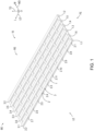
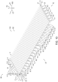
- Fig. 1 shows an exemplary structural flooring panel 10 for a construction system, as seen in an isometric or perspective view.
- a "structural flooring panel” is a panel for a building or construction system that is capable of supporting - or serving as - a floor.
- the panel 10 is arranged to lie in a substantially horizontal plane OLW.
- the panel 10 is wood-based.
- a panel may be considered to be "wood-based” when 15% or more of the global volume of the panel is occupied by wood, wood-based strips, and/or wood-based elements.
- a strip may be considered to be "wood-based” when it has a composition of at least 50 % wood by volume and/or by mass, and/or is composed of one or more wood-based elements.
- an element may be considered to be "wood-based” when it comprises at least 50 % wood by volume and/or by mass.
- a wood-based element or strip may be made partially or entirely of a wood-polymer composite as disclosed in P06, incorporated herein by reference to the fullest extent permitted under local patent law.
- the material used to make a wood-based strip/element is referred to herein as "wood-based material”.
- the panel 10 includes a front end FE and a back end BE arranged at opposing extremities of the panel as considered along a lengthwise direction LD of the panel.
- the lengthwise direction LD of the panel 10 is parallel to the plane OLW.
- the panel 10 includes a left end LE and a right end RE arranged along a widthwise direction WD of the panel.
- the widthwise direction WD of the panel 10 is parallel to the plane OLW, and is substantially orthogonal to the lengthwise direction LD.
- two directions are "substantially orthogonal" to one another when their projections onto a plane parallel to both directions form a right angle or an acute angle of 80 degrees or more.
- a thickness direction TD of the panel 10 is appreciated as being substantially orthogonal to the panel's lengthwise direction LD and widthwise direction WD.
- the panel 10 includes strips arranged in a first ply 1, a second ply 2, and a third ply 3.
- the first ply 1, the second ply 2, and the third ply 3 are arranged in series with one another along the thickness direction TD of the panel 10.
- the first ply 1 includes a first strip 1.1, a second strip 1.2, and a third strip 1.3.
- the first strip is wood-based.
- a wood-based element presents a length, a width, and a thickness.
- a strip or element when a strip or element is described as being “oriented along” or “extending along” a given direction, it should be understood that the length of the strip or element is in this direction.
- the "width” of a strip or element denotes a dimension perpendicular to the length of the strip or element and parallel to the plane OLW.
- the "thickness" of a strip or element denotes a dimension orthogonal to the length and width of the strip or element.
- a strip - be it composed of multiple elements or not - will generally be fixed to other strips in the panel at least at its lengthwise extremities.
- two or more elements and/or strips within a given panel be composed of different wood-based materials from one another.
- one wood-based material may contain a first species of wood
- another wood-based material may contain a second species of wood.
- two different wood-based materials may contain a different concentration of wood from one another.
- the first strip 1.1 of the first ply 1 may have a width of 100 mm (millimeters) or more and 250 mm or less, as measured in the plane OLW perpendicular to the panel's lengthwise direction LD. However, other widths are contemplated.
- the first strip 1.1 of the first ply 1 may have a thickness of 20 mm or more to 300 mm or less, as measured in a thickness direction TD, which is perpendicular to the plane OLW.
- TD thickness direction
- other thicknesses are contemplated.
- an increase in the thickness of strips in a given ply can lead to an increase in the amount space available within the interior of the panel for accommodation of functional elements.
- functional elements refer to components which are primarily intended to provide functions to the panel other than merely resistance to loading. Insulation elements, ventilation elements (such as mechanical and/or flow guidance components), plumbing elements, wiring elements, etc. are all non-limiting examples of functional elements.
- the first strip 1.1 of the first ply 1 is arranged on the left end LE of the panel 10 and extends along the lengthwise direction LD of the panel.
- the second strip 1.2 of the first ply 1 differs from the first strip 1.1 of the first ply in that the second strip of the first ply is arranged on the right end RE of the panel 10.
- the third strip 1.3 of the first ply 1 differs from the second strip 1.2 of the first ply in that the third strip of the first ply is arranged at a position in the widthwise direction WD of the panel 10 that is intermediate the first strip 1.1 of the first ply and the second strip of the first ply.
- first ply 1 Although only three strips have been described in detail for the first ply 1, it is contemplated to provide the first ply with more than one strip arranged at a position in the widthwise direction WD of the panel 10 that is intermediate the first ply's first strip 1.1 and second strip 1.2.
- Fig. 1 shows the first ply 1 as having four strips (1.3, 1.4, 1.5, 1.6) arranged at positions in the widthwise direction WD of the panel 10 that are intermediate the first ply's first strip 1.1 and second strip 1.2.
- Other quantities are contemplated for such "intermediate strips" of the first ply 1 besides one (as described) or four (as illustrated), for example two, three, five, or more.
- Increasing the number of intermediate strips of a given ply may increase the ability of the panel 10 to support loads in the gravity direction (typically - but in a non-limiting fashion - the thickness direction TD).
- the second ply 2 is adjacent to the first ply 1 and includes a first strip 2.1, a second strip 2.2, and a third strip 2.3.
- the first strip 2.1 of the second ply 2 is fixed to the first strip 1.1 of the first ply 1, the second strip 1.2 of the first ply, the third strip 1.3 of the first ply. Fixation of the first strip 2.1 of the second ply 2 to a given strip of the first ply 1 may be accomplished as described in P07. When additional intermediate strips of the first ply 1 are present, the first strip 2.1 of the second ply 2 may also be attached to some/all of said additional intermediate strips of the first ply, in the same manner.
- the first strip 2.1 of the second ply 2 differs from the first strip 1.1 of the first ply 1 in that the first strip 2.1 of the second ply 2 is arranged on the front end FE of the panel 10 and extends along the widthwise direction WD of the panel.
- the second strip 2.2 of the second ply 2 differs from the first strip 2.1 of the second ply in that the second strip of the second ply is arranged on the back end BE of the panel 10.
- the third strip 2.3 of the second ply 2 differs from the second strip 2.2 of the second ply in that the third strip of the second ply is arranged at a position in the lengthwise direction LD of the panel 10 that is intermediate the first strip 2.1 of the second ply and the second strip of the second ply.
- Fig. 1 shows the second ply 2 as having nine strips (2.3, 2.4, 2.5, 2.6, 2.7, 2.8, 2.9, 2.10, 2.11) arranged at positions in the lengthwise direction LD of the panel 10 that are intermediate the second ply's first strip 2.1 and second strip 2.2.
- Other quantities are contemplated for such "intermediate strips" of the second ply 1 besides one (as described) or nine (as illustrated), for example two, three, five, six, seven, eight, ten or more.
- the third ply 3 differs from the first ply 1 in that the third ply is arranged on an opposite side of the second ply 2 from the first ply, as considered in the thickness direction TD of the panel 10.
- the second ply 2 is also fixed to the third ply 3, for example in the same manner used to fix the second ply to the first ply 1.
- the third ply 3 may cooperate with the first ply 1 to stabilize the second ply 2.
- Fig. 2-17 show panels with five plies, in the same view as used for Fig. 1 , discussion of each of these panels' first, second, and third plies is respectively applicable to the first, second, and third plies of panel having as few as three plies. Moreover, discussion of each of these panels' fourth plies is applicable to the fourth ply of a panel having as few as four plies. Additionally, panels with more than five plies are contemplated, and so discussion of a first ply, a second ply, a third ply, a fourth ply, or a fifth ply of a panel with three, four, or five plies is also applicable to such plies of a panel with more than five plies.
- a panel's strength may be increased by increasing the number of plies it contains.
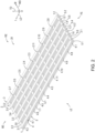
- Fig. 2 shows an exemplary panel 20, which differs from the panel 10 described with respect to Fig. 1 in that the panel 20 includes a fourth ply 4.
- the fourth ply 4 differs from the second ply 2 of the panel 20 as follows.
- the position of the fourth ply 4 along the thickness direction TD of the panel 20 is such that the first ply 1 is positioned intermediate the second ply 2 and the fourth ply.
- the strips of the fourth ply are not fixed to those of the third ply.
- the fourth ply 4 may cooperate with the second ply 2 to stabilize the first ply 1.
- the panel 20 may also include a fifth ply 5.
- the fifth ply 5 differs from the first ply 1 in that the fifth ply is arranged on an opposite side of the fourth ply 4 from the first ply, as considered in the thickness direction TD of the panel 20.
- the strips of the fifth ply 5 are not fixed to those of the second ply 2; however, the strips of the fourth ply 4 are fixed to those of the fifth ply, for example in the same manner used to fix the fourth ply to the first ply 1.
- the fifth ply 5 may cooperate with the first ply 1 to stabilize the fourth ply 4.
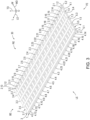
- Fig. 3 shows an exemplary panel 30, which differs from the panel 20 described with respect to Fig. 2 as follows.
- the spacings of intermediate strips 2.3, 2.4, 2.5... of the second ply 2 relative to their respective neighboring strips within the second ply vary when moving along the lengthwise direction of the panel.
- each intermediate strip of the second ply 2 is arranged nearer in the lengthwise direction LD to its neighbor that is disposed towards the nearest extremity in the lengthwise direction than it is to its other neighbor.
- Such a configuration may increase the ability of the panel 10 to withstand shear loads (in a substantially vertical plane parallel to the panel's lengthwise direction LD) while limiting the amount of wood in the panel, by providing reinforcement against such loads in areas where such loading is highest.
- shear loads in a substantially vertical plane parallel to the panel's lengthwise direction LD
- other variations in spacing within a given ply are contemplated.
- FIG. 3 shows the second ply 2 as having twenty-one intermediate strips, variations in spacing within a given ply are contemplated with more than twenty one intermediate strips, or as few as twenty, nineteen, eighteen, seventeen, sixteen, fifteen, fourteen, thirteen, twelve, or eleven intermediate strips, or any other quantity of intermediate strips disclosed herein.
- the first ply 1 illustrated in Fig. 3 has only three intermediate strips; however, the number of intermediate strips in the first ply is without incidence on the remarks presented above for the second ply 2 illustrated in Fig. 3 - indeed these remarks are applicable for any quantity of intermediate strips disclosed herein for the first ply.
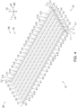
- Fig. 4 shows an exemplary panel 40 which differs from the panel 20 described with respect to Fig. 2 as follows.
- the first ply 1 has 5 intermediate strips, but any other quantity disclosed herein for quantities of intermediate strips of the first ply, the third ply 3, or the fifth ply 5 (when present) is also contemplated.
- the second ply has 19 intermediate strips, but any other quantity disclosed herein for quantities of intermediate strips of the second ply 2 or the fourth ply 4 (when present) is also contemplated.
- the thickness of the third ply 3 may be different from the thickness of the first ply 1.
- the thickness of the second ply 2 is different from the thickness of the first ply 1 and/or the thickness of the third ply 3.
- Fig. 5 shows an exemplary panel 50 which differs from the panel 40 described with respect to Fig. 4 as follows.
- the first ply 1 has 4 intermediate strips, but any other quantity disclosed herein is also contemplated.
- the second ply 2 has 9 intermediate strips, but any other quantity disclosed herein is also contemplated.
- the fourth ply 4 has a different thickness from the second ply 2. Although the fourth ply 4 is illustrated as being thinner than the second ply 2, an inverse relationship is also contemplated.
- the thickness of the fifth ply 5 may be different from the thickness of the first ply 1 and/or the thickness of the third ply 3. Although the fifth ply 5 is illustrated as being thicker than the first ply and thinner than the third ply, the contrary of one or both of these relationships is/are contemplated.
- Variations in ply thicknesses are contemplated for each panel described herein. Generally, an increase in ply thickness gives rise to an increase in ply strength.
- Fig. 6 shows an exemplary panel 60 which differs from the panel 20 described with respect to Fig. 2 as follows.
- each strip of the second ply 2 is different from (illustrated as greater than, though less than is also contemplated) the width of each strip of the first ply 1.
- two or more strips within a given ply have different widths from one another.
- the first ply, the second ply, and/or the third ply may have different thicknesses from one another, and/or from the thickness(es) of the fourth ply (when present) and/or of the fifth ply (when present).
- Fig. 7 shows an exemplary panel 70, which differs from the panel 20 described with respect to Fig. 2 as follows.
- the first ply 1 has 5 intermediate strips, but any other quantity disclosed herein is also contemplated.
- the second ply 2 has 19 intermediate strips, but any other quantity disclosed herein is also contemplated.
- the third ply 3 is "filled” with intermediate strips.
- a ply can be considered “filled” when no two neighboring strips within the ply that are oriented along a common direction to one another are separated by a distance of more than 2 centimeters (cm) as measured perpendicular to said direction. Such strips may even adjoin one another.
- a filled uppermost ply may allow the panel to provide a walkable surface for the construction system.
- the strips of the uppermost ply may have a relatively uniform thickness to one another, so that the walkable surface may be relatively flat.
- an uppermost ply that is not filled may be made to support one or more superficial layers in order to provide a walkable surface for the construction system.
- the thickness of the filled ply's strips may be selected to allow the strips to withstand demands associated with possible exposure of the strips to traffic (walking, rolling, sliding%), storage (furniture, merchandise, equipment, machinery%), and the environment (humidity, aesthetic and/or maintenance products, maintenance activities).
- the term "uppermost ply” refers to the third ply 3 in a panel with three, four, our five plies. If more plies are present, then the uppermost ply of the panel is whichever ply is arranged on the same side of the second ply as the third ply and furthest from the second ply, as considered along the thickness direction TD.
- the term “uppermost” refers to the fact that, when the panel is in use as flooring in a construction system, it would typically (though in a non-limiting fashion) be placed substantially horizontally, such that the "uppermost ply" is arranged farthest from the ground.
- Fig. 8 shows an exemplary panel 80, which differs from the panel 70 described with respect to Fig. 7 as follows.
- the lowermost ply (fifth ply 5 in the illustration) is filled.
- the term "lowermost ply” refers to the fifth ply 5 in a panel with five plies (as illustrated, for example), the fourth ply 4 in a panel with four plies, and the first ply 1 in a panel with three plies.
- Use of the term “lowermost ply” denotes that whatever is disclosed with respect to the lowermost ply illustrated in the relevant figure is also contemplated for the lowermost ply of a panel with a different number of plies.
- the term "lowermost ply” designates whichever ply is located on the same side of the first ply as the fifth ply, and furthest from the first ply, as considered along the thickness direction TD.
- the panel When the lowermost ply is filled, the panel may provide a ceiling for the construction system.
- a filled lowermost ply may allow for functional elements installed in the panel to be concealed, as viewed from below the panel.
- the thickness of the strips of the lowermost ply may be selected according to the mechanical and/or environmental requirements associated with providing a ceiling and/or supporting functional elements from below.
- the panel 80 With both its uppermost ply (third ply 3) and its lowermost ply (fifth ply 5) filled, the panel 80 has one or more intermediate plies (in this case the first ply 1, the second ply 2, and the fourth ply 4), which are not filled, separating a pair of filled plies in the thickness direction TD.
- intermediate plies in this case the first ply 1, the second ply 2, and the fourth ply 4
- the panel 80 includes one or more enclosed spaces between the filled plies.
- An enclosed space within a panel may be understood as a three-dimensional region delimited on either side in the thickness direction TD by filled plies of the panel.
- the intermediate strip(s) of the open ply may divide the three-dimensional region between the filled plies into multiple enclosed spaces.
- the three-dimensional region between the filled plies may remain undivided.
- Fig. 9 shows an exemplary panel 90, which differs from the panel 80 described with respect to Fig. 8 as follows.
- the strips of the third ply 3 are thicker than they are wide.
- the third ply 3 is not filled; however, it is also contemplated for the strips of the third ply 3 of any of the panels described herein to be thicker than they are wide, without regard for whether any ply of the panel is filled or not filled.
- Using strips that are thicker than they are wide in the uppermost ply may facilitate installation of functional elements from above.
- Fig. 10 shows an exemplary panel 100, which differs from the panel 80 described with respect to Fig. 8 as follows.
- the strips of the lowermost ply are thicker than they are wide.
- the lowermost ply is not filled.
- strips that are thicker than they are wide in the lowermost ply may facilitate installation of functional elements from below.
- Fig. 11 shows an exemplary panel 110, which differs from the panel 80 described with respect to Fig. 8 as follows.
- the strips of the median ply are thicker than they are wide.
- the term “median ply” refers to the first ply 1 in a panel with five plies, the first and/or second ply 2 in a panel with four plies, and the second ply in a panel with three plies.
- Use of the term “median ply” denotes that whatever is disclosed with respect to the median ply illustrated in the relevant figure is also contemplated for the median ply of a panel with a different number of plies.
- the strips of the median ply (or median plies) of any of the panels described herein may be thicker than they are wide, without regard for whether any ply of the panel is filled or not filled.
- Using strips that are thicker than they are wide in the median ply (or median plies) may substantially increase the distance between the panel's uppermost ply and lowermost ply while incurring minor or no increases in material use.
- any ply (or plies) of any panel disclosed herein to include one or more strips that are thicker than they are wide.
- Fig. 12 shows an exemplary panel 120, which differs from the panel 20 described with respect to Fig. 2 as follows.
- the first ply 1 has 3 intermediate strips, but any other quantity disclosed herein is also contemplated.
- the second ply 2 has 17 intermediate strips, but any other quantity disclosed herein is also contemplated.
- the intermediate strips of the second ply 2 are oriented along a first direction D1, which is different from the lengthwise direction LD and the widthwise direction WD.
- the first direction D1 may define an acute angle ⁇ 1 with respect to the panel's lengthwise direction LD of 30 degrees or more to 60 degrees or less.
- other ranges for the angle ⁇ 1 defined by the first direction D1 and the panel's lengthwise direction LD are also contemplated, such as 30 degrees or more to 55 degrees or less, 30 degrees or more to 50 degrees or less, 30 degrees or more to 48 degrees or less, 30 degrees or more to 45 degrees or less, 35 degrees or more to 60 degrees or less, 35 degrees or more to 55 degrees or less, 35 degrees or more to 50 degrees or less, 35 degrees or more to 48 degrees or less, 35 degrees or more to 45 degrees or less, 40 degrees or more to 60 degrees or less, 40 degrees or more to 55 degrees or less, 40 degrees or more to 50 degrees or less, 40 degrees or more to 48 degrees or less, 40 degrees or more to 45 degrees or less, 42 degrees or more to 60 degrees or less, 42 degrees or more to 55 degrees or less, 42 degrees or more to 50 degrees or less, 42 degrees or more to 48 degrees or less, 42 degrees
- the third strip 2.3 of the second ply 2 is fixed to at least two strips of the first 1 and/or second 2 ply (plies) - this may be true for some or all of any other intermediate strips (if present) of the second ply.
- the intermediate strip(s) of the second ply is/are offset from a position where the first strip 1.1 of the first ply 1 and the first strip 2.1 of the second ply 2 are attached to each other, as considered along a direction within the plane OLW perpendicular to the first direction D1.
- Such orientation is also contemplated for the fourth ply (when present), regardless of whether such orientation is present in the second ply.
- the orientation and arrangement of the third strip 2.3 (and/or other intermediate strip/s) of the second ply 2 may increase the ability of the panel to support shear loads within the plane OLW.
- the strip(s) of the second ply oriented along the first direction D1 provide relatively large contributions to the strength of the panel against bending in the lengthwise direction LD. However, for the amount of wood that they contain, but relatively small (but nonzero) contributions to the strength of the panel against bending in the widthwise direction WD.
- the strip(s) of the second ply oriented along the first direction D1 provide relatively small (but nonzero) contributions to the strength of the panel against bending in the lengthwise direction LD, while preserving relatively large contributions to the strength of the panel against bending in the widthwise direction WD.
- the strip(s) of the second ply oriented in the first direction D1 offer favorable combinations of contributions to the strength of the panel against bending in the lengthwise direction LD and in the widthwise direction WD, in view of the amount of wood used.
- the second ply's contribution to the strength of the panel against bending in the lengthwise direction increases, it may be possible to reduce the number of strips and/or the width(s) and/or thickness(es) of one or more strips in an odd-numbered ply. Such a reduction in the amount of wood used in the odd-numbered ply may help to compensate for the increased amount of wood used in the second ply.
- Strips of the fourth ply 4 are indicated using reference numerals with dashed lead lines when the strips themselves are hidden in the present view.
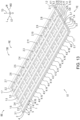
- Fig. 13 shows an exemplary panel 130, which differs from the panel 20 described with respect to Fig. 2 as follows.
- the first ply 1 has five intermediate strips, but six or more, or any other quantity of intermediate strips disclosed for the first ply are also contemplated.
- the third ply 3 illustrated in Fig. 13 has two intermediate strips; however, the following discussion of the first ply 1 and third ply 3 illustrated in Fig. 13 is applicable to any numbers of intermediate strips of these plies, as long as the third ply has at least one intermediate strip.
- the first ply 1 includes at least one superposed intermediate strip and at least one non-superposed intermediate strip.
- Each superposed intermediate strip of the first ply 1 is arranged in the widthwise direction WD of the panel 130 so as to be in superposition with an intermediate strip of the third ply 3.
- Each non-superposed intermediate strip of the first ply 1 is arranged in the widthwise direction WD of the panel 130 so as to neighbor a superposed intermediate strip of the first ply without itself being in superposition with an intermediate strip of the third ply 3.
- the first ply's intermediate strips may be arranged such that superposed and non-superposed intermediate strips alternate with one another when viewed along the widthwise direction.
- Fig. 13 shows the first ply 1 as having more intermediate strips than the third ply 3, it is also contemplated for this relationship to be reversed - in this case, the third ply has the superposed intermediate strip(s) and the non-superposed intermediate strip(s), but the remainder of the foregoing discussion remains applicable.
- the fourth ply 4 incudes at least one superposed intermediate strip and at least one non-superposed intermediate strip.
- Each superposed intermediate strip of the fourth ply 4 is arranged in the lengthwise direction LD of the panel 130 so as to be in superposition with an intermediate strip of the second ply 2.
- Each non-superposed intermediate strip of the fourth ply 4 is arranged in the lengthwise direction LD of the panel 130 so as to neighbor a superposed intermediate strip of the fourth ply without itself being in superposition with an intermediate strip of the second ply 2.
- Fig. 13 shows the fourth ply 4 as having more intermediate strips than the second ply 2, it is also contemplated for this relationship to be reversed - in this case, the second ply has the superposed intermediate strip(s) and the non-superposed intermediate strip(s), but the remainder of the foregoing discussion remains applicable.
- first ply 1 and third ply 3 may be applicable with respect to the fifth ply and one or more of the first and third plies, independently of whether the intermediate strips of the first ply and the third ply are arranged to ensure or avoid superposition with each other.
- the superposition of intermediate strips of plies of like parity creates columns in oriented in the thickness direction TD of the panel 130.
- the superposition of some-but-not-all intermediate strips in a given ply of non-unique parity may result in reduced wood use in the panel as a whole.
- first ply 1 is shown as having five intermediate strips, any other quantity of intermediate strips disclosed herein for the first ply is contemplated insofar as it differs from the quantity of intermediate strips in the first ply (and/or the fifth ply, when present).
- fourth ply 4 when present is shown as having 19 intermediate strips, any other quantity of intermediate strips disclosed herein for the fourth ply (or second ply 2) is contemplated insofar as it differs from the quantity of intermediate strips in the second ply.
- Fig. 14 shows an exemplary panel 140 which differs from the panel 130 described with respect to Fig. 13 in that the intermediate strips of a given ply of non-unique parity are arranged to reduce superposition with intermediate strips of one or more other plies of like parity.
- Fig. 14 shows plies of like parity having differing numbers of intermediate strips, the contrary is also contemplated.
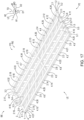
- Fig. 15 shows an exemplary panel 150, which differs from the panel 120 discussed with respect to Fig. 12 as follows.
- the intermediate strips of the fourth ply 4 are oriented along a second direction D2, which is different from the lengthwise direction LD, the widthwise direction WD, and the first direction D1, and are offset from a position where the second strip 1.2 of the first ply 1 and the first strip 2.1 of the second ply 2 are attached to each other, as considered along a direction within the plane OLW perpendicular to the second direction D2.
- first direction D1 and the second direction D2 have a common component to one another, as considered along the lengthwise direction LD, and opposite components
- the second direction D2 defines an acute angle ⁇ 2 with respect to the panel's lengthwise direction LD of 30 degrees or more to 60 degrees or less.
- other ranges for the angle defined by D2 are also contemplated, such as 30 degrees or more to 55 degrees or less, 30 degrees or more to 50 degrees or less, 30 degrees or more to 48 degrees or less, 30 degrees or more to 45 degrees or less, 35 degrees or more to 60 degrees or less, 35 degrees or more to 55 degrees or less, 35 degrees or more to 50 degrees or less, 35 degrees or more to 48 degrees or less, 35 degrees or more to 45 degrees or less, 40 degrees or more to 60 degrees or less, 40 degrees or more to 55 degrees or less, 40 degrees or more to 50 degrees or less, 40 degrees or more to 48 degrees or less, 40 degrees or more to 45 degrees or less, 42 degrees or more to 60 degrees or less, 42 degrees or more to 55 degrees or less, 42 degrees or more to 50 degrees or less, 42 degrees or more to 48 degrees or less, 42 degrees or more to 45 degrees or less, 45 degrees or more to 60 degrees or less
- the acute angle ⁇ 2 defined by the second direction D2 and the panel's lengthwise direction LD may be independent of the acute angle ⁇ 1 defined by the first direction D1 and the panel's lengthwise direction LD.
- the angles ⁇ 1 and ⁇ 2 are arranged on opposite sides with respect to the lengthwise direction LD: the first direction D1 extends towards the left end LE of the panel with respect to the lengthwise direction LD, and the second direction D2 extends towards the right end RE of the panel with respect to the lengthwise direction, or vice versa.
- the second ply is able to strengthen the panel against bending loads along the lengthwise direction LD thanks to the strip(s) oriented along the first direction D1; however, as the(se) strip(s) is/are subjected to these loads, it/they induce(s) a component to the deflection of the panel that is oriented along the widthwise direction WD.
- the fourth ply also strengthens the panel against bending loads in the lengthwise direction LD thanks to the strip(s) oriented along the second direction D2, and induces a component to the deflection of the panel that is oriented along the widthwise direction WD, but counter to the component induced by the second ply.
- Fig. 16 shows an exemplary panel 160, which differs from the panel 20 described with respect to Fig. 2 as follows.
- the first ply 1 has 3 intermediate strips, but any other quantity disclosed herein is also contemplated.
- the second ply 2 has 33 intermediate strips, but it is also contemplated to have 34 or more, or as few as 31, 30, 29, 28, 27, 26, 25, 24, 23, or any other quantity disclosed herein.
- the second ply 2 has a first set of one or more intermediate strip(s) and a second set of one or more intermediate strip(s).
- the first set of intermediate strips of the second ply 2 is oriented along the first direction D1 discussed in connection with Fig. 12 & 15 .
- the second set of intermediate strips of the second ply 2 is oriented along the second direction D2 discussed in connection with Fig. 15 .
- the first set of intermediate strips of the second ply 2 is fixed to at least one of the first strip 1.1 of the first ply 1 and the third strip 1.3 of the first ply.
- the second set of intermediate strips of the second ply 2 is fixed to at least one of the second strip 1.2 of the first ply 1 and the third strip 1.3 of the first ply.
- the third strip 2.3 of the second ply 2 is optionally parallel to the second ply's first strip 2.1 and second strip 2.2.
- the second ply 2 optionally has a third set of one or more intermediate strip(s) and a fourth set of one or more intermediate strip(s).
- the third set of intermediate strips of the second ply 2 may be oriented along the second direction D2 and fixed to at least one of the first strip 1.1 of the first ply 1 and the third strip 1.3 of the first ply.
- the fourth set of intermediate strips of the second ply 2 may be oriented along the first direction D1 and fixed to at least one of the second strip 1.2 of the first ply 1 and the third strip 1.3 of the first ply.
- Strips of the fourth ply 4 are indicated using reference numerals with dashed lead lines when the strips themselves are hidden in the present view.
- Fig. 17 shows an exemplary panel 170, which differs from the panel 160 described with respect to Fig. 16 as follows.
- the second ply 2 has a different number of intermediate strips from the fourth ply 4, but the contrary is also contemplated.
- the intermediate strips of the second ply 2 are arranged to be superposed on some-but-not-all of the intermediate strips of the fourth ply 4, as described with respect to Fig. 13 ; however, it is also contemplated for the intermediate strips of the second ply to be arranged to not be superposed on any of the intermediate strips of the fourth ply, as described with respect to Fig. 14 .
- Strips of the fourth ply 4 are indicated using reference numerals with dashed lead lines when the strips themselves are hidden in the present view.
- Fig. 18 shows a schematic sectional view of a portion a construction system including a wall and an exemplary wood-based structural flooring panel 180.
- the panel 180 may be any panel as disclosed herein.
- the panel 180 may be attached to the wall using the same techniques used for CLT flooring panels.
- the wall may be provided using one or more wood-based load-bearing panels 11, 12 as disclosed in P07.
- the wall includes a horizontal-facing recess 13 in which an end (illustrated here as the front end FE, though the right end, the back end, and the left end are each contemplated as well) of the structural flooring panel 180 is received, such that the flooring panel's lowermost ply rests on the lower surface 14 of the recess 13, the end of the flooring panel 180 faces the wall, and the flooring panel's uppermost ply faces the upper surface 15 of the recess 13.
- a construction system, or building comprise multiple such walls and flooring panels 180.
- Fig. 19 shows a schematic sectional view of a portion of a construction system including a beam 21 and multiple structural flooring panels 190, 191.
- Each panel 190, 191 may be any panel as disclosed herein.
- FIG. 19 shows two flooring panels 190, 191, it is contemplated for more or fewer flooring panels to be used as needed.
- the beam 21 presents a recess 23 in which the (front, back, left, right) end of a flooring panel 190, 191 is received.
- Each flooring panel 190, 191 is secured to the beam 21 by means of screws, which traverses the beam 21 and terminates in the first ply of the flooring panel 190.
- first and/or second strips of a given ply be composed of multiple adjoining wood-based elements arranged so as to produce a strip(s) that is/are wider than the intermediate strip(s) of the ply, in order to increase shear resistance of the ply and/or to facilitate fastening of the panel within the construction system or building.
- FIG. 19 shows the second strips 2.2, 4.2 of the second 2 and fourth 4 plies of the panel 191 being composed of a first element 2.2A, 4.2A and a second element 2.2B, 4.2B, and the first strips 2.1, 4.1 of the second 2 and fourth 4 plies of the panel 190 as being composed of a first element 2.1A, 4.1A and a second element 2.1B, 4.1B, such a configuration is contemplated for any first and/or second strip of any ply of any panel disclosed herein.
- edges of the panels shown in the above-described drawings are shown as having openings along their edges, defined in the thickness direction TD by consecutive plies of like parity and defined in the lengthwise and/or widthwise direction(s) by strips of these plies' common neighboring ply, it is contemplated for one or more edges of a given panel to be at least partially closed. Closure or partial closure of an edge of a panel may be accomplished by providing one or more strips in the common neighboring ply which (collectively) contact(s) both of the strips of said ply that define the opening in the lengthwise and/or widthwise direction(s), and which (collectively) contact(s) the strips of both of the plies that define the opening in the thickness direction. Closure or partial closure of one or more edges of a given panel may improve insulation properties, and/or limit or prevent ingress/egress of fluids and/or animals at the construction site and/or during the lifetime of the building/construction system.
- At least the second ply contains two neighboring strips which at some position in the widthwise direction are separated by more than 2 cm (centimeters) in the lengthwise direction.
- at least the first ply contains at least two neighboring strips which at some position in the lengthwise direction are separated by more than 2 cm (centimeters) in the widthwise direction.
- at least the fourth ply contains at least two neighboring strips which at some position in the widthwise direction are separated by more than 2 cm (centimeters) in the lengthwise direction.
- neighboring flooring panels may be joined to one another through known means.
Landscapes
- Engineering & Computer Science (AREA)
- Architecture (AREA)
- Civil Engineering (AREA)
- Structural Engineering (AREA)
- Life Sciences & Earth Sciences (AREA)
- Wood Science & Technology (AREA)
- Physics & Mathematics (AREA)
- Electromagnetism (AREA)
- Floor Finish (AREA)
Abstract
Wood-based structural flooring panel (10) for use in a construction system, and building or construction system comprising same. The panel comprises a series of at least three superimposed plies in a substantially horizontal plane (OLW) wherein:
a first ply (1) of the series of plies comprises first (1.1), second (1.2), and third (1.3) wood-based strips, which are distributed along the first ply, and which are oriented in a lengthwise direction (LD) of the panel, the first strip of the first ply being arranged at a left end (LE) of the panel, the second strip of the first ply being arranged at a right end (RE) of the panel, and the third strip of the first ply being arranged intermediate the first and second strips of the first ply;
a second ply (2) of the series of plies, adjacent to the first ply, comprises first (2.1) and second (2.2) wood-based strips, which are distributed along the second ply, and which are oriented in a widthwise direction (WD) of the panel, the first strip of the second ply being arranged at a front end (FE) of the panel, the second strip of the second ply being arranged at a back end (BE) of the panel, the first and second strips of the second ply each being attached to the first, second, and third strips of the first ply by attachment means; and
a third ply (3) of the series of plies, adjacent to the second ply such that the second ply is intermediate the first and third plies, comprises first (3.1) and second (3.2) wood-based strips, which are distributed along the third ply, and which are oriented in the lengthwise direction, the first strip of the third ply being arranged at the left end of the panel and attached to the first and second strips of the second ply by attachment means, the second strip of the third ply being arranged at the right end of the panel and attached to the first and second strips of the second ply by attachment means.
a first ply (1) of the series of plies comprises first (1.1), second (1.2), and third (1.3) wood-based strips, which are distributed along the first ply, and which are oriented in a lengthwise direction (LD) of the panel, the first strip of the first ply being arranged at a left end (LE) of the panel, the second strip of the first ply being arranged at a right end (RE) of the panel, and the third strip of the first ply being arranged intermediate the first and second strips of the first ply;
a second ply (2) of the series of plies, adjacent to the first ply, comprises first (2.1) and second (2.2) wood-based strips, which are distributed along the second ply, and which are oriented in a widthwise direction (WD) of the panel, the first strip of the second ply being arranged at a front end (FE) of the panel, the second strip of the second ply being arranged at a back end (BE) of the panel, the first and second strips of the second ply each being attached to the first, second, and third strips of the first ply by attachment means; and
a third ply (3) of the series of plies, adjacent to the second ply such that the second ply is intermediate the first and third plies, comprises first (3.1) and second (3.2) wood-based strips, which are distributed along the third ply, and which are oriented in the lengthwise direction, the first strip of the third ply being arranged at the left end of the panel and attached to the first and second strips of the second ply by attachment means, the second strip of the third ply being arranged at the right end of the panel and attached to the first and second strips of the second ply by attachment means.
Description
- The present disclosure relates to the field of buildings, construction systems, and panels therefor, particularly those using wood-based structural members in flooring applications.
- Within the present disclosure, a "construction system" refers to a plurality of structural elements in structural cooperation with one another to define a space in which vertical and/or horizontal incursion and/or excursion of electromagnetic radiation, fluid, and/or one or more solids is limited or prevented. For example, a construction system is typically used to limit vertical and/or horizontal incursion and/or excursion of light, wind, precipitation, and/or animal life into and/or out of a space.
- Within the present disclosure, a "building" refers to a construction system defining an enclosed space.
- It is known to use so-called cross-laminated timber (CLT) panels to serve as flooring within a building/construction system. Such panels are defined according to standard EN 16351 - Timber Structures - Cross Laminated Timber - Requirements. The current version of the standard in effect is EN 16351:2021.
- The inventor(s) have realized that a need exists for a wood-based structural flooring panel that offers requires less wood than is needed for CLT panels, while still ensuring suitable structural performance for use in buildings and/or construction systems, and which may be even adaptable in terms of its construction to meet local performance and/or functional requirements within a building and/or construction system.
- To that end, the inventor(s) provide a wood-based structural flooring panel for use in a construction system, the panel comprising a series of at least three superimposed plies in a substantially horizontal plane.
- A first ply of the series of plies comprises first, second, and third wood-based strips, which are distributed along the first ply, and which are oriented in a lengthwise direction of the panel.
- The first strip of the first ply is arranged at a left end of the panel.
- The second strip of the first ply is arranged at a right end of the panel.
- The third strip of the first ply is arranged intermediate the first and second strips of the first ply and offset from the first and second strips of the first ply in a widthwise direction of the panel.
- A second ply of the series of plies, adjacent to the first ply, comprises first and second wood-based strips, which are distributed along the second ply, and which are oriented in a widthwise direction of the panel.
- The first strip of the second ply is arranged at a front end of the panel.
- The second strip of the second ply being arranged at a back end of the panel.
- The first and second strips of the second ply each are attached to the first, second, and third strips of the first ply by attachment means.
- A third ply of the series of plies, adjacent to the second ply such that the second ply is intermediate the first and third plies, comprises first and second wood-based strips, which are distributed along the third ply, and which are oriented in the lengthwise direction.
- The first strip of the third ply is arranged at the left end of the panel and attached to the first and second strips of the second ply by attachment means.
- The second strip of the third ply is arranged at the right end of the panel and attached to the first and second strips of the second ply by attachment means.
- The third strip of the first ply may be offset from each of the first and second strips of the first ply such that a gap between the third strip of the first ply and the first strip of the first ply measures more than 15 cm (centimeters) in the widthwise direction, and such that a gap between the third strip of the first ply and the second strip of the first ply measures more than 15 cm (centimeters) in the widthwise direction.
- An uppermost ply of the series of plies may comprise one or more wood-based strips, arranged parallel to the uppermost ply's first and second strips so as to adjoin one or both of them, or so as to be separated from one or both of them by a gap of 2 centimeters or less as measured perpendicular to said one or more strips and parallel to the substantially horizontal plane. Each of said one or more strips of the uppermost ply may be attached by attachment means to the first and second strips of a ply adjacent to the uppermost ply.
- Thus, the panel may present a filled uppermost ply.
- Additionally or alternatively, a lowermost ply of the series of plies may comprise one or more wood-based strips, arranged parallel to the lowermost ply's first and second strips so as to adjoin one or both of them, or so as to be separated from one or both of them by a gap of 2 centimeters or less (for example less than 5 millimeters, or 5 to 20 millimeters inclusive) as measured perpendicular to said one or more strips and parallel to the substantially horizontal plane. Each of said one or more strips of the lowermost ply may be attached by attachment means to the first and second strips of a ply adjacent to the lowermost ply.
- Thus, the panel may present a filled lowermost ply.
- A thickness, as measured normal to the substantially horizontal plane, of the strips in a given ply of the series of plies, may be greater than a width of one of said strips, as measured in the substantially horizontal plane and perpendicular to a length of said one of said strips.
- Thus, the strips of a given ply may be thicker than they are wide.
- The second ply may comprise a third wood-based strip, intermediate the first and second strips of the second ply, oriented along a first direction, which is different from the lengthwise and widthwise directions, and attached to the first and second strips of the first and third plies and to the third strip of the first ply by attachment means.
- Such an orientation may strengthen the panel against shearing within the substantially horizontal plane. Such an orientation may allow the second ply's third strip to contribute to the strength of the panel in bending along the panel's lengthwise direction.
- The second ply may comprise third and fourth wood-based strips, intermediate the first and second strips of the second ply. The second ply's third strip may be oriented in a first direction, different from the lengthwise and widthwise directions, and attached to the first and third strips of the first ply by attachment means. The second ply's fourth strip may be oriented in a second direction, different from the lengthwise, widthwise, and first directions, and attached to the second and third strips of the first ply by attachment means.
- The panel may thus include multiple strips oriented in multiple directions, which are different from each other and from the panel's lengthwise and widthwise directions. The use of multiple directions may allow for improved mechanical performance of the panel under certain types of loading.
- Since the first and second directions are different from each other, the second ply's third and fourth strips may be attached to one another by attachment means, so as to allow at least some force to be transmitted between the second ply's third and fourth strips while bypassing the first and third plies.
- The first and second directions may be selected such that the second ply's third strip is attached to the first ply's first strip nearer to the front end of the panel than the position where the second ply's third strip is attached to the first ply's third strip, and the second ply's fourth strip is attached to the first ply's second strip nearer to the front end of the panel than the position where the second ply's fourth strip is attached to the first ply's third strip.
- The second ply may comprise fifth, sixth, and seventh wood-based strips. The fifth strip of the second ply may be intermediate the first and second strips of the second ply, and oriented in the widthwise direction. The third and fourth strips of the second ply may be intermediate the first and fifth strips of the second ply. The sixth and seventh strips of the second ply may be intermediate the second and fifth strips of the second ply. The seventh strip of the second ply may be oriented along the first direction, and attached to the second and third strips of the first ply by attachment means. The sixth strip of the second ply may be oriented along the second direction, and attached to the first and third strips of the first ply by attachment means.
- The second ply may thus include a first set of strips oriented along the first and second directions near the front end of the panel, an opposing second set of strips oriented along the first and second directions near the back end of the panel, and a strip oriented along the widthwise direction separating the first and second sets of strips from one another.
- An acute angle between the lengthwise direction and the first direction may be 45 degrees, or within an angular range. The angular range may 30 degrees or more to 60 degrees or less, 30 degrees or more to 55 degrees or less, 30 degrees or more to 50 degrees or less, 30 degrees or more to 48 degrees or less, 30 degrees or more to 45 degrees or less, 35 degrees or more to 60 degrees or less, 35 degrees or more to 55 degrees or less, 35 degrees or more to 50 degrees or less, 35 degrees or more to 48 degrees or less, 35 degrees or more to 45 degrees or less, 40 degrees or more to 60 degrees or less, 40 degrees or more to 55 degrees or less, 40 degrees or more to 50 degrees or less, 40 degrees or more to 48 degrees or less, 40 degrees or more to 45 degrees or less, 42 degrees or more to 60 degrees or less, 42 degrees or more to 55 degrees or less, 42 degrees or more to 50 degrees or less, 42 degrees or more to 48 degrees or less, 42 degrees or more to 45 degrees or less, 45 degrees or more to 60 degrees or less, 45 degrees or more to 55 degrees or less, 45 degrees or more to 50 degrees or less, or 45 degrees or more to 48 degrees or less.
- As the acute angle between the first direction and the lengthwise direction decreases, the length(s) of the second ply's third strip increases in order to ensure contact with the strips of the first ply to which it is attached, but the second ply's third strip's contribution to strengthening the panel against bending loads in the lengthwise direction increases as well.
- The first and second directions may intersect one another. An acute angle between the lengthwise direction and the second direction may be 45 degrees, or within an angular range. The angular range may 30 degrees or more to 60 degrees or less, 30 degrees or more to 55 degrees or less, 30 degrees or more to 50 degrees or less, 30 degrees or more to 48 degrees or less, 30 degrees or more to 45 degrees or less, 35 degrees or more to 60 degrees or less, 35 degrees or more to 55 degrees or less, 35 degrees or more to 50 degrees or less, 35 degrees or more to 48 degrees or less, 35 degrees or more to 45 degrees or less, 40 degrees or more to 60 degrees or less, 40 degrees or more to 55 degrees or less, 40 degrees or more to 50 degrees or less, 40 degrees or more to 48 degrees or less, 40 degrees or more to 45 degrees or less, 42 degrees or more to 60 degrees or less, 42 degrees or more to 55 degrees or less, 42 degrees or more to 50 degrees or less, 42 degrees or more to 48 degrees or less, 42 degrees or more to 45 degrees or less, 45 degrees or more to 60 degrees or less, 45 degrees or more to 55 degrees or less, 45 degrees or more to 50 degrees or less, or 45 degrees or more to 48 degrees or less.
- When a strip oriented in the first direction is subjected to bending in the lengthwise direction, the strip may have a tendency to deflect in the widthwise direction. This deflection may be counteracted at least partially by an opposing tendency arising from subjecting a strip oriented in the second direction to bending in the lengthwise direction.
- The second ply may comprise a third wood-based strip neighboring the first strip of the second ply, and a fourth wood-based strip neighboring the second strip of the second ply. A separation distance, as measured in the lengthwise direction, between the first and third strips of the second ply, may be greater than a separation distance, as measured in the lengthwise direction, between the third strip of the second ply and a neighboring strip of the second ply's third strip arranged towards the back end with respect to the third strip of the second ply. Additionally or alternatively, a separation distance, as measured in the lengthwise direction, between the second and fourth strips of the second ply, may be greater than a separation distance, as measured in the lengthwise direction, between the fourth strip of the second ply and a neighboring strip of the second ply's fourth strip arranged towards the front end with respect to the fourth strip of the second ply.
- Thus, spacing may be varied to provide localized strengthening of the panel against certain loading phenomena.
- A given third-or-higher-numbered strip of one ply of the series of plies and a corresponding third-or-higher-numbered strip of another ply of the series of plies, of like parity to the one ply of the series of plies, may be arranged parallel to one another and non-overlapping one another when viewed normal to the substantially horizontal plane.
- The absence of overlap may improve acoustic insulation by discouraging resonance and/or sound propagation within the panel. Additionally or alternatively, the absence of overlap may improve thermal insulation by disrupting thermal bridges within the panel in the thickness direction of the panel. Additionally or alternatively, the absence of overlap may facilitate integration of functional elements within the panel because strips of plies of like parity occupy different horizontal positions from one another.
- The panel may comprise a fourth ply of the series of plies, adjacent to the first ply such that the first ply is intermediate the second and fourth plies. The fourth ply may comprise first and second wood-based strips, which are distributed along the fourth ply, and which are oriented in the widthwise direction. The first strip of the fourth ply may be arranged at the front end of the panel and attached to the first and second strips of the first ply by attachment means. The second strip of the fourth ply may be arranged at the back end of the panel and attached to the first and second strips of the first ply by attachment means.
- The fourth ply may help to stabilize the first ply.
- Additionally, the panel may comprise a fifth ply of the series of plies, adjacent to the fourth ply such that the fourth ply is intermediate the first and fifth plies. The fifth ply may comprise first and second wood-based strips, which are distributed along the fifth ply, and which are oriented in the lengthwise direction. The first strip of the fifth ply may be arranged at the left end of the panel and attached to the first and second strips of the fourth ply by attachment means. The second strip of the fifth ply may be arranged at the right end of the panel and attached to the first and second strips of the fourth ply by attachment means.
- The fifth ply may help to stabilize the fourth ply.
- The fourth ply may comprise a third wood-based strip, intermediate the first and second strips of the fourth ply, and attached to the first, second, and third strips of the first ply by attachment means. The fourth ply's third strip may be oriented along the first direction, or along a second direction, which is different from the lengthwise, widthwise, and first directions.
- The panel may be provided with multiple plies having one or more strips oriented obliquely to the lengthwise and widthwise directions, possibly in multiple directions oblique to the lengthwise and widthwise directions.
- The fourth ply may comprise third and fourth wood-based strips, intermediate the first and second strips of the fourth ply. The third strip of the fourth ply may be attached to the first and third strips of the first ply by attachment means. The fourth strip of the fourth ply may be attached to the second and third strips of the first ply by attachment means. The third and fourth strips of the fourth ply may respectively be oriented along the first and second directions, or vice versa.
- A given ply may contain multiple strips oriented in different directions obliquely to the lengthwise and widthwise directions.
- The fourth ply may comprise fifth, sixth, and seventh wood-based strips. The fifth strip of the fourth ply may be intermediate the first and second strips of the fourth ply and oriented in the widthwise direction. The third and fourth strips of the fourth ply may be intermediate the first and fifth strips of the fourth ply. The sixth and seventh strips of the fourth ply may be intermediate the second and fifth strips of the fourth ply. The sixth strip of the fourth ply may be attached to the second and third strips of the first ply by attachment means. The seventh strip of the fourth ply may be attached to the first and third strips of the first ply by attachment means. The sixth and seventh strips of the fourth ply may respectively be oriented along the first and second directions, or vice versa.
- The panel may include multiple plies with multiple strips oriented in different directions obliquely to the lengthwise and widthwise directions.
- The inventor(s) also propose a building or construction system comprising a panel as described earlier herein.
- The disclosure may be more completely understood in consideration of the following detailed description of aspects of the disclosure in connection with the accompanying drawings, in which:
-
Fig. 1 shows an isometric or perspective view of an exemplary wood-based structural flooring panel for a construction system. -
Fig. 2 shows an isometric or perspective view of an exemplary wood-based structural flooring panel, presenting more than three plies, for a construction system. -
Fig. 3 shows an isometric or perspective view of an exemplary wood-based structural flooring panel, presenting a ply in which strip spacing is variable, for a construction system. -
Fig. 4 shows an isometric or perspective view of an exemplary wood-based structural flooring panel, presenting plies of different thicknesses, for a construction system. -
Fig. 5 shows an isometric or perspective view of an exemplary wood-based structural flooring panel, presenting plies of different thicknesses, for a construction system. -
Fig. 6 shows an isometric or perspective view of an exemplary wood-based structural flooring panel, presenting strips of different widths, for a construction system. -
Fig. 7 shows an isometric or perspective view of an exemplary wood-based structural flooring panel, presenting a filled ply, for a construction system. -
Fig. 8 shows an isometric or perspective view of an exemplary wood-based structural flooring panel, presenting multiple filled plies, for a construction system. -
Fig. 9 shows an isometric or perspective view of an exemplary wood-based structural flooring panel, presenting a(n uppermost) ply with strips that are thicker than they are wide, for a construction system. -
Fig. 10 shows an isometric or perspective view of an exemplary wood-based structural flooring panel, a (lowermost) ply with strips that are thicker than they are wide, for a construction system. -
Fig. 11 shows an isometric or perspective view of an exemplary wood-based structural flooring panel, one or more median plies with strips that are thicker than they are wide, for a construction system. -
Fig. 12 shows an isometric or perspective view of an exemplary wood-based structural flooring panel, presenting at least one ply with strips oriented obliquely to the panel's length direction and width direction, for a construction system. -
Fig. 13 shows an isometric or perspective view of an exemplary wood-based structural flooring panel, presenting superposition of some but not all intermediate strips of plies of like parity, for a construction system. -
Fig. 14 shows an isometric or perspective view of an exemplary wood-based structural flooring panel, plies an absence of superposition of all intermediate strips of plies of like parity, for a construction system. -
Fig. 15 shows an isometric or perspective view of an exemplary wood-based structural flooring panel, presenting at least one ply with strips oriented obliquely to the panel's length direction and width direction, at least another ply with strips oriented obliquely or perpendicularly to the orientation of the strips of said at least one ply, and obliquely to the panel's length direction and width direction, for a construction system. -
Fig. 16 shows an isometric or perspective view of an exemplary wood-based structural flooring panel, presenting at least one ply with strips oriented obliquely to the panel's length direction and width direction and to each other, for a construction system. -
Fig. 17 shows an isometric or perspective view of an exemplary wood-based structural flooring panel, presenting at least one ply with strips oriented obliquely to the panel's length direction and width direction and to each other, and at least another ply with strips oriented obliquely to the panel's length direction and width direction and to each other, the intermediate strips of said at least one ply being superposed on some but not all of the intermediate strips of said at least another ply, for a construction system. -
Fig. 18 shows a sectional view of an interface between a load-bearing panel and a structural flooring panel in a construction system. -
Fig. 19 shows a sectional view of an interface between a load-bearing beam and a structural flooring panel in a construction system. - The term "exemplary" is used in the sense of "example," rather than "ideal." While aspects of the disclosure are amenable to various modifications and alternative forms, specifics thereof have been shown by way of example in the drawings and will be described in detail. It should be understood, however, that the intention is not to limit aspects of the disclosure to the particular embodiment(s) described. On the contrary, the intention of this disclosure is to cover all modifications, equivalents, and alternatives falling within the scope of the disclosure.
- As used in this disclosure and the appended claims, the singular forms "a", "an", and "the" include plural referents unless the content clearly dictates otherwise. As used in this disclosure and the appended claims, the term "or" is generally employed in its sense including "and/or" unless the content clearly dictates otherwise.
- The following detailed description should be read with reference to the drawings. The detailed description and the drawings, which are not necessarily to scale, depict illustrative aspects and are not intended to limit the scope of the disclosure. The illustrative aspects depicted are intended only as exemplary.
- Although the terms "first," "second," etc. may be used herein to describe various panels, buildings, construction systems, levels, floors, ceilings, walls, roofs, strips, plies, layers, steps, elements, components, regions, layers, sections, and/or parameters, these panels, buildings, construction systems, levels, floors, ceilings, walls, roofs, strips, plies, layers, steps, elements, components, regions, layers, sections, and/or parameters should not be limited by these terms. These terms are only used to distinguish one panel, building, construction system, level, floor, ceiling, wall, roof, strip, ply, layer, step, element, component, region, layer, section, or parameter, from another panel, building, construction system, level, floor, ceiling, wall, roof, strip, ply, layer, step, element, component, region, layer, section, or parameter. Thus, a first panel, building, construction system, level, floor, ceiling, wall, roof, strip, ply, layer, step, element, component, region, layer, section, and/or parameter discussed herein could be termed a second panel, building, construction system, level, floor, ceiling, wall, roof, strip, ply, layer, step, element, component, region, layer, section, and/or parameter without departing from the teachings of the present inventive subject matter.
- Herein, "P01" stands for application
PCT/FR2017/052723 PCT/EP2018/054936 PCT/EP2018/071166 PCT/EP2021/025339 PCT/EP2021/025340 PCT/EP2022/052986 PCT/EP2022/057658 -
Fig. 1 shows an exemplarystructural flooring panel 10 for a construction system, as seen in an isometric or perspective view. As used in the present disclosure, a "structural flooring panel" is a panel for a building or construction system that is capable of supporting - or serving as - a floor. - The
panel 10 is arranged to lie in a substantially horizontal plane OLW. - The
panel 10 is wood-based. Within the present disclosure, a panel may be considered to be "wood-based" when 15% or more of the global volume of the panel is occupied by wood, wood-based strips, and/or wood-based elements. Within the present disclosure, a strip may be considered to be "wood-based" when it has a composition of at least 50 % wood by volume and/or by mass, and/or is composed of one or more wood-based elements. Within the present disclosure, an element may be considered to be "wood-based" when it comprises at least 50 % wood by volume and/or by mass. As a non-limiting example, a wood-based element or strip may be made partially or entirely of a wood-polymer composite as disclosed in P06, incorporated herein by reference to the fullest extent permitted under local patent law. The material used to make a wood-based strip/element is referred to herein as "wood-based material". - The
panel 10 includes a front end FE and a back end BE arranged at opposing extremities of the panel as considered along a lengthwise direction LD of the panel. The lengthwise direction LD of thepanel 10 is parallel to the plane OLW. - The
panel 10 includes a left end LE and a right end RE arranged along a widthwise direction WD of the panel. The widthwise direction WD of thepanel 10 is parallel to the plane OLW, and is substantially orthogonal to the lengthwise direction LD. As used herein, two directions are "substantially orthogonal" to one another when their projections onto a plane parallel to both directions form a right angle or an acute angle of 80 degrees or more. - A thickness direction TD of the
panel 10 is appreciated as being substantially orthogonal to the panel's lengthwise direction LD and widthwise direction WD. - The
panel 10 includes strips arranged in afirst ply 1, asecond ply 2, and athird ply 3. Thefirst ply 1, thesecond ply 2, and thethird ply 3 are arranged in series with one another along the thickness direction TD of thepanel 10. - The
first ply 1 includes a first strip 1.1, a second strip 1.2, and a third strip 1.3. - The first strip is wood-based.
- Generally, a wood-based element, or a wood-based strip, presents a length, a width, and a thickness. Within the present disclosure, when a strip or element is described as being "oriented along" or "extending along" a given direction, it should be understood that the length of the strip or element is in this direction. Within the present disclosure, the "width" of a strip or element denotes a dimension perpendicular to the length of the strip or element and parallel to the plane OLW. Within the present disclosure, the "thickness" of a strip or element denotes a dimension orthogonal to the length and width of the strip or element. A strip - be it composed of multiple elements or not - will generally be fixed to other strips in the panel at least at its lengthwise extremities.
- It is contemplated that two or more elements and/or strips within a given panel be composed of different wood-based materials from one another. As a non-limiting example, one wood-based material may contain a first species of wood, and another wood-based material may contain a second species of wood. Additionally or alternatively, two different wood-based materials may contain a different concentration of wood from one another.
- The first strip 1.1 of the
first ply 1 may have a width of 100 mm (millimeters) or more and 250 mm or less, as measured in the plane OLW perpendicular to the panel's lengthwise direction LD. However, other widths are contemplated. - As a non-limiting example, the first strip 1.1 of the
first ply 1 may have a thickness of 20 mm or more to 300 mm or less, as measured in a thickness direction TD, which is perpendicular to the plane OLW. However, other thicknesses are contemplated. - Generally, an increase in the thickness of strips in a given ply can lead to an increase in the amount space available within the interior of the panel for accommodation of functional elements.
- As used herein, "functional elements" refer to components which are primarily intended to provide functions to the panel other than merely resistance to loading. Insulation elements, ventilation elements (such as mechanical and/or flow guidance components), plumbing elements, wiring elements, etc. are all non-limiting examples of functional elements.
- The first strip 1.1 of the
first ply 1 is arranged on the left end LE of thepanel 10 and extends along the lengthwise direction LD of the panel. - The second strip 1.2 of the
first ply 1 differs from the first strip 1.1 of the first ply in that the second strip of the first ply is arranged on the right end RE of thepanel 10. - The third strip 1.3 of the
first ply 1 differs from the second strip 1.2 of the first ply in that the third strip of the first ply is arranged at a position in the widthwise direction WD of thepanel 10 that is intermediate the first strip 1.1 of the first ply and the second strip of the first ply. - Although only three strips have been described in detail for the
first ply 1, it is contemplated to provide the first ply with more than one strip arranged at a position in the widthwise direction WD of thepanel 10 that is intermediate the first ply's first strip 1.1 and second strip 1.2. For example,Fig. 1 shows thefirst ply 1 as having four strips (1.3, 1.4, 1.5, 1.6) arranged at positions in the widthwise direction WD of thepanel 10 that are intermediate the first ply's first strip 1.1 and second strip 1.2. Other quantities are contemplated for such "intermediate strips" of thefirst ply 1 besides one (as described) or four (as illustrated), for example two, three, five, or more. - Increasing the number of intermediate strips of a given ply may increase the ability of the
panel 10 to support loads in the gravity direction (typically - but in a non-limiting fashion - the thickness direction TD). - The
second ply 2 is adjacent to thefirst ply 1 and includes a first strip 2.1, a second strip 2.2, and a third strip 2.3. - The first strip 2.1 of the
second ply 2 is fixed to the first strip 1.1 of thefirst ply 1, the second strip 1.2 of the first ply, the third strip 1.3 of the first ply. Fixation of the first strip 2.1 of thesecond ply 2 to a given strip of thefirst ply 1 may be accomplished as described in P07. When additional intermediate strips of thefirst ply 1 are present, the first strip 2.1 of thesecond ply 2 may also be attached to some/all of said additional intermediate strips of the first ply, in the same manner. - The first strip 2.1 of the
second ply 2 differs from the first strip 1.1 of thefirst ply 1 in that the first strip 2.1 of thesecond ply 2 is arranged on the front end FE of thepanel 10 and extends along the widthwise direction WD of the panel. - The second strip 2.2 of the
second ply 2 differs from the first strip 2.1 of the second ply in that the second strip of the second ply is arranged on the back end BE of thepanel 10. - The third strip 2.3 of the
second ply 2 differs from the second strip 2.2 of the second ply in that the third strip of the second ply is arranged at a position in the lengthwise direction LD of thepanel 10 that is intermediate the first strip 2.1 of the second ply and the second strip of the second ply. - Although only three strips have been described in detail for the
second ply 2, it is contemplated to provide the second ply with more than one strip arranged at a position in the lengthwise direction LD of thepanel 10 that is intermediate the second ply's first strip 2.1 and second strip 2.2. For example,Fig. 1 shows thesecond ply 2 as having nine strips (2.3, 2.4, 2.5, 2.6, 2.7, 2.8, 2.9, 2.10, 2.11) arranged at positions in the lengthwise direction LD of thepanel 10 that are intermediate the second ply's first strip 2.1 and second strip 2.2. Other quantities are contemplated for such "intermediate strips" of thesecond ply 1 besides one (as described) or nine (as illustrated), for example two, three, five, six, seven, eight, ten or more. - The
third ply 3 differs from thefirst ply 1 in that the third ply is arranged on an opposite side of thesecond ply 2 from the first ply, as considered in the thickness direction TD of thepanel 10. Thesecond ply 2 is also fixed to thethird ply 3, for example in the same manner used to fix the second ply to thefirst ply 1. - The
third ply 3 may cooperate with thefirst ply 1 to stabilize thesecond ply 2. - Although
Fig. 2-17 show panels with five plies, in the same view as used forFig. 1 , discussion of each of these panels' first, second, and third plies is respectively applicable to the first, second, and third plies of panel having as few as three plies. Moreover, discussion of each of these panels' fourth plies is applicable to the fourth ply of a panel having as few as four plies. Additionally, panels with more than five plies are contemplated, and so discussion of a first ply, a second ply, a third ply, a fourth ply, or a fifth ply of a panel with three, four, or five plies is also applicable to such plies of a panel with more than five plies. - Generally, a panel's strength may be increased by increasing the number of plies it contains.
-
Fig. 2 shows anexemplary panel 20, which differs from thepanel 10 described with respect toFig. 1 in that thepanel 20 includes afourth ply 4. - The
fourth ply 4 differs from thesecond ply 2 of thepanel 20 as follows. - The position of the
fourth ply 4 along the thickness direction TD of thepanel 20 is such that thefirst ply 1 is positioned intermediate thesecond ply 2 and the fourth ply. The strips of the fourth ply are not fixed to those of the third ply. - The
fourth ply 4 may cooperate with thesecond ply 2 to stabilize thefirst ply 1. - As seen in
Fig. 2 , thepanel 20 may also include afifth ply 5. - The
fifth ply 5 differs from thefirst ply 1 in that the fifth ply is arranged on an opposite side of thefourth ply 4 from the first ply, as considered in the thickness direction TD of thepanel 20. The strips of thefifth ply 5 are not fixed to those of thesecond ply 2; however, the strips of thefourth ply 4 are fixed to those of the fifth ply, for example in the same manner used to fix the fourth ply to thefirst ply 1. - The
fifth ply 5 may cooperate with thefirst ply 1 to stabilize thefourth ply 4. -
Fig. 3 shows anexemplary panel 30, which differs from thepanel 20 described with respect toFig. 2 as follows. - Rather than being evenly-distributed in the lengthwise direction LD of the
panel 30, the spacings of intermediate strips 2.3, 2.4, 2.5... of thesecond ply 2 relative to their respective neighboring strips within the second ply vary when moving along the lengthwise direction of the panel. - Specifically, each intermediate strip of the
second ply 2 is arranged nearer in the lengthwise direction LD to its neighbor that is disposed towards the nearest extremity in the lengthwise direction than it is to its other neighbor. Such a configuration may increase the ability of thepanel 10 to withstand shear loads (in a substantially vertical plane parallel to the panel's lengthwise direction LD) while limiting the amount of wood in the panel, by providing reinforcement against such loads in areas where such loading is highest. However, other variations in spacing within a given ply are contemplated. - Although
Fig. 3 shows thesecond ply 2 as having twenty-one intermediate strips, variations in spacing within a given ply are contemplated with more than twenty one intermediate strips, or as few as twenty, nineteen, eighteen, seventeen, sixteen, fifteen, fourteen, thirteen, twelve, or eleven intermediate strips, or any other quantity of intermediate strips disclosed herein. - Remarks for the
second ply 2 illustrated inFig. 3 also apply to thefourth ply 4 illustrated inFig. 3 , however it is also contemplated for plies of like parity to employ differing spacings from one another (e.g. one ply with constant spacing and another ply of like parity with variable spacing, or one ply with one spacing variation and another ply of like parity with another spacing variation...). - Rather than having four intermediate strips as illustrated for the
first ply 1 inFig. 2 , thefirst ply 1 illustrated inFig. 3 has only three intermediate strips; however, the number of intermediate strips in the first ply is without incidence on the remarks presented above for thesecond ply 2 illustrated inFig. 3 - indeed these remarks are applicable for any quantity of intermediate strips disclosed herein for the first ply. - Remarks for the
first ply 1 illustrated inFig. 3 also apply to thethird ply 3 and to thefifth ply 5. - Regardless of the number of plies present in the panel, the above-described variations in spacing are considered for application, mutatis mutandis, to the first ply and/or third ply (and/or fifth ply, when present), regardless of whether such variations are employed in the panel's second ply (and/or fourth ply, when present).
- Variations in spacings between neighboring strips within a given ply, as discussed with respect to
Fig. 3 , are also contemplated for each panel described herein. -
Fig. 4 shows anexemplary panel 40 which differs from thepanel 20 described with respect toFig. 2 as follows. - The
first ply 1 has 5 intermediate strips, but any other quantity disclosed herein for quantities of intermediate strips of the first ply, thethird ply 3, or the fifth ply 5 (when present) is also contemplated. - The second ply has 19 intermediate strips, but any other quantity disclosed herein for quantities of intermediate strips of the
second ply 2 or the fourth ply 4 (when present) is also contemplated. - The thickness of the
third ply 3 may be different from the thickness of thefirst ply 1. - The thickness of the
second ply 2 is different from the thickness of thefirst ply 1 and/or the thickness of thethird ply 3. -
Fig. 5 shows anexemplary panel 50 which differs from thepanel 40 described with respect toFig. 4 as follows. - The
first ply 1 has 4 intermediate strips, but any other quantity disclosed herein is also contemplated. - The
second ply 2 has 9 intermediate strips, but any other quantity disclosed herein is also contemplated. - The
fourth ply 4 has a different thickness from thesecond ply 2. Although thefourth ply 4 is illustrated as being thinner than thesecond ply 2, an inverse relationship is also contemplated. - The thickness of the
fifth ply 5 may be different from the thickness of thefirst ply 1 and/or the thickness of thethird ply 3. Although thefifth ply 5 is illustrated as being thicker than the first ply and thinner than the third ply, the contrary of one or both of these relationships is/are contemplated. - Variations in ply thicknesses, as described with respect to
Fig. 4 and/orFig. 5 , are contemplated for each panel described herein. Generally, an increase in ply thickness gives rise to an increase in ply strength. -
Fig. 6 shows anexemplary panel 60 which differs from thepanel 20 described with respect toFig. 2 as follows. - The width of each strip of the
second ply 2 is different from (illustrated as greater than, though less than is also contemplated) the width of each strip of thefirst ply 1. - Moreover, it is contemplated that two or more strips within a given ply have different widths from one another.
- Optionally, and without regard for the width of any strip in any ply of the
panel 60, the first ply, the second ply, and/or the third ply may have different thicknesses from one another, and/or from the thickness(es) of the fourth ply (when present) and/or of the fifth ply (when present). - Variations in strip widths, as described with respect to
Fig. 6 , are contemplated for each panel described herein. -
Fig. 7 shows anexemplary panel 70, which differs from thepanel 20 described with respect toFig. 2 as follows. - The
first ply 1 has 5 intermediate strips, but any other quantity disclosed herein is also contemplated. - The
second ply 2 has 19 intermediate strips, but any other quantity disclosed herein is also contemplated. - The
third ply 3 is "filled" with intermediate strips. As used herein, a ply can be considered "filled" when no two neighboring strips within the ply that are oriented along a common direction to one another are separated by a distance of more than 2 centimeters (cm) as measured perpendicular to said direction. Such strips may even adjoin one another. - It is also contemplated to fill the
third ply 3 of any of the panels discussed above. - A filled uppermost ply may allow the panel to provide a walkable surface for the construction system. The strips of the uppermost ply may have a relatively uniform thickness to one another, so that the walkable surface may be relatively flat.
- In contrast, an uppermost ply that is not filled may be made to support one or more superficial layers in order to provide a walkable surface for the construction system.
- When a filled ply is used to provide a walkable surface for the construction system, the thickness of the filled ply's strips may be selected to allow the strips to withstand demands associated with possible exposure of the strips to traffic (walking, rolling, sliding...), storage (furniture, merchandise, equipment, machinery...), and the environment (humidity, aesthetic and/or maintenance products, maintenance activities...).
- As used in the present disclosure, the term "uppermost ply" refers to the
third ply 3 in a panel with three, four, our five plies. If more plies are present, then the uppermost ply of the panel is whichever ply is arranged on the same side of the second ply as the third ply and furthest from the second ply, as considered along the thickness direction TD. The term "uppermost" refers to the fact that, when the panel is in use as flooring in a construction system, it would typically (though in a non-limiting fashion) be placed substantially horizontally, such that the "uppermost ply" is arranged farthest from the ground. -
Fig. 8 shows anexemplary panel 80, which differs from thepanel 70 described with respect toFig. 7 as follows. - The lowermost ply (
fifth ply 5 in the illustration) is filled. - As used in the present disclosure, the term "lowermost ply" refers to the
fifth ply 5 in a panel with five plies (as illustrated, for example), thefourth ply 4 in a panel with four plies, and thefirst ply 1 in a panel with three plies. Use of the term "lowermost ply" denotes that whatever is disclosed with respect to the lowermost ply illustrated in the relevant figure is also contemplated for the lowermost ply of a panel with a different number of plies. - When the panel includes more than five plies, the term "lowermost ply" designates whichever ply is located on the same side of the first ply as the fifth ply, and furthest from the first ply, as considered along the thickness direction TD.
- It is also contemplated to fill the lowermost ply of any of the panels described above.
- When the lowermost ply is filled, the panel may provide a ceiling for the construction system.
- A filled lowermost ply may allow for functional elements installed in the panel to be concealed, as viewed from below the panel.
- The thickness of the strips of the lowermost ply may be selected according to the mechanical and/or environmental requirements associated with providing a ceiling and/or supporting functional elements from below.
- With both its uppermost ply (third ply 3) and its lowermost ply (fifth ply 5) filled, the
panel 80 has one or more intermediate plies (in this case thefirst ply 1, thesecond ply 2, and the fourth ply 4), which are not filled, separating a pair of filled plies in the thickness direction TD. - Because the filled plies are separated from one another in the thickness direction TD, the
panel 80 includes one or more enclosed spaces between the filled plies. An enclosed space within a panel may be understood as a three-dimensional region delimited on either side in the thickness direction TD by filled plies of the panel. - When only a single open ply separates a pair of filled plies, the intermediate strip(s) of the open ply may divide the three-dimensional region between the filled plies into multiple enclosed spaces.
- When multiple consecutive unfilled plies separate a pair of filled plies, the three-dimensional region between the filled plies may remain undivided.
-
Fig. 9 shows an exemplary panel 90, which differs from thepanel 80 described with respect toFig. 8 as follows. - The strips of the
third ply 3 are thicker than they are wide. - The
third ply 3 is not filled; however, it is also contemplated for the strips of thethird ply 3 of any of the panels described herein to be thicker than they are wide, without regard for whether any ply of the panel is filled or not filled. - Using strips that are thicker than they are wide in the uppermost ply (in this case the third ply 3) may facilitate installation of functional elements from above.
-
Fig. 10 shows anexemplary panel 100, which differs from thepanel 80 described with respect toFig. 8 as follows. - The strips of the lowermost ply (
fifth ply 5 in the illustration) are thicker than they are wide. - Optionally, and without regard for whether the strips of the lowermost ply are thicker than they are wide, the lowermost ply is not filled.
- It is also contemplated for the strips of the lowermost ply of any of the panels described herein to be thicker than they are wide.
- Using strips that are thicker than they are wide in the lowermost ply may facilitate installation of functional elements from below.
-
Fig. 11 shows anexemplary panel 110, which differs from thepanel 80 described with respect toFig. 8 as follows. - The strips of the median ply (
first ply 1 in the illustration) are thicker than they are wide. - As used in the present disclosure, the term "median ply" refers to the
first ply 1 in a panel with five plies, the first and/orsecond ply 2 in a panel with four plies, and the second ply in a panel with three plies. Use of the term "median ply" denotes that whatever is disclosed with respect to the median ply illustrated in the relevant figure is also contemplated for the median ply of a panel with a different number of plies. - It is also contemplated for the strips of the median ply (or median plies) of any of the panels described herein to be thicker than they are wide, without regard for whether any ply of the panel is filled or not filled.
- Using strips that are thicker than they are wide in the median ply (or median plies) may substantially increase the distance between the panel's uppermost ply and lowermost ply while incurring minor or no increases in material use.
- More generally, it is contemplated for any ply (or plies) of any panel disclosed herein to include one or more strips that are thicker than they are wide.
-
Fig. 12 shows anexemplary panel 120, which differs from thepanel 20 described with respect toFig. 2 as follows. - The
first ply 1 has 3 intermediate strips, but any other quantity disclosed herein is also contemplated. - The
second ply 2 has 17 intermediate strips, but any other quantity disclosed herein is also contemplated. - The intermediate strips of the
second ply 2 are oriented along a first direction D1, which is different from the lengthwise direction LD and the widthwise direction WD. - The first direction D1 may define an acute angle θ1 with respect to the panel's lengthwise direction LD of 30 degrees or more to 60 degrees or less. However, other ranges for the angle θ1 defined by the first direction D1 and the panel's lengthwise direction LD are also contemplated, such as 30 degrees or more to 55 degrees or less, 30 degrees or more to 50 degrees or less, 30 degrees or more to 48 degrees or less, 30 degrees or more to 45 degrees or less, 35 degrees or more to 60 degrees or less, 35 degrees or more to 55 degrees or less, 35 degrees or more to 50 degrees or less, 35 degrees or more to 48 degrees or less, 35 degrees or more to 45 degrees or less, 40 degrees or more to 60 degrees or less, 40 degrees or more to 55 degrees or less, 40 degrees or more to 50 degrees or less, 40 degrees or more to 48 degrees or less, 40 degrees or more to 45 degrees or less, 42 degrees or more to 60 degrees or less, 42 degrees or more to 55 degrees or less, 42 degrees or more to 50 degrees or less, 42 degrees or more to 48 degrees or less, 42 degrees or more to 45 degrees or less, 45 degrees or more to 60 degrees or less, 45 degrees or more to 55 degrees or less, 45 degrees or more to 50 degrees or less, or 45 degrees or more to 48 degrees or less.
- The third strip 2.3 of the
second ply 2 is fixed to at least two strips of the first 1 and/or second 2 ply (plies) - this may be true for some or all of any other intermediate strips (if present) of the second ply. - The intermediate strip(s) of the second ply is/are offset from a position where the first strip 1.1 of the
first ply 1 and the first strip 2.1 of thesecond ply 2 are attached to each other, as considered along a direction within the plane OLW perpendicular to the first direction D1. - Such orientation is also contemplated for the fourth ply (when present), regardless of whether such orientation is present in the second ply.
- Orientation of the intermediate strip(s) of the second ply and/or fourth ply along the first direction is contemplated for each of the panels described above.
- Orienting the second ply's third (and/or other intermediate) strip(s) along the first direction D1 allows it (them) to contribute to the strength of the panel against bending in the lengthwise direction LD and in the widthwise direction WD, while incurring only a limited increase in the amount of wood present in the panel. Additionally or alternatively, the orientation and arrangement of the third strip 2.3 (and/or other intermediate strip/s) of the
second ply 2 may increase the ability of the panel to support shear loads within the plane OLW. - At lower values of θ1 (e.g. 30 to 37.5 degrees inclusive), the strip(s) of the second ply oriented along the first direction D1 provide relatively large contributions to the strength of the panel against bending in the lengthwise direction LD. However, for the amount of wood that they contain, but relatively small (but nonzero) contributions to the strength of the panel against bending in the widthwise direction WD.
- At higher values of θ1 (e.g. 52.5 to 60 degrees inclusive), the strip(s) of the second ply oriented along the first direction D1 provide relatively small (but nonzero) contributions to the strength of the panel against bending in the lengthwise direction LD, while preserving relatively large contributions to the strength of the panel against bending in the widthwise direction WD.
- At intermediate values of θ1 (e.g. 45 degrees, or any of the abovementioned ranges with bounds between 37.5 and 52.5 degrees), the strip(s) of the second ply oriented in the first direction D1 offer favorable combinations of contributions to the strength of the panel against bending in the lengthwise direction LD and in the widthwise direction WD, in view of the amount of wood used.
- As the second ply's contribution to the strength of the panel against bending in the lengthwise direction increases, it may be possible to reduce the number of strips and/or the width(s) and/or thickness(es) of one or more strips in an odd-numbered ply. Such a reduction in the amount of wood used in the odd-numbered ply may help to compensate for the increased amount of wood used in the second ply.
- Strips of the fourth ply 4 (when present) are indicated using reference numerals with dashed lead lines when the strips themselves are hidden in the present view.
-
Fig. 13 shows anexemplary panel 130, which differs from thepanel 20 described with respect toFig. 2 as follows. - The
first ply 1 has five intermediate strips, but six or more, or any other quantity of intermediate strips disclosed for the first ply are also contemplated. - The
third ply 3 illustrated inFig. 13 has two intermediate strips; however, the following discussion of thefirst ply 1 andthird ply 3 illustrated inFig. 13 is applicable to any numbers of intermediate strips of these plies, as long as the third ply has at least one intermediate strip. - The
first ply 1 includes at least one superposed intermediate strip and at least one non-superposed intermediate strip. Each superposed intermediate strip of thefirst ply 1 is arranged in the widthwise direction WD of thepanel 130 so as to be in superposition with an intermediate strip of thethird ply 3. Each non-superposed intermediate strip of thefirst ply 1 is arranged in the widthwise direction WD of thepanel 130 so as to neighbor a superposed intermediate strip of the first ply without itself being in superposition with an intermediate strip of thethird ply 3. - Superposition / non-superposition of intermediate strips of plies of like parity can be appreciated as viewed along the thickness direction TD of the
panel 130. - As a non-limiting example, the first ply's intermediate strips may be arranged such that superposed and non-superposed intermediate strips alternate with one another when viewed along the widthwise direction.
- Although
Fig. 13 shows thefirst ply 1 as having more intermediate strips than thethird ply 3, it is also contemplated for this relationship to be reversed - in this case, the third ply has the superposed intermediate strip(s) and the non-superposed intermediate strip(s), but the remainder of the foregoing discussion remains applicable. - The
fourth ply 4 incudes at least one superposed intermediate strip and at least one non-superposed intermediate strip. Each superposed intermediate strip of thefourth ply 4 is arranged in the lengthwise direction LD of thepanel 130 so as to be in superposition with an intermediate strip of thesecond ply 2. Each non-superposed intermediate strip of thefourth ply 4 is arranged in the lengthwise direction LD of thepanel 130 so as to neighbor a superposed intermediate strip of the fourth ply without itself being in superposition with an intermediate strip of thesecond ply 2. - Although
Fig. 13 shows thefourth ply 4 as having more intermediate strips than thesecond ply 2, it is also contemplated for this relationship to be reversed - in this case, the second ply has the superposed intermediate strip(s) and the non-superposed intermediate strip(s), but the remainder of the foregoing discussion remains applicable. - The foregoing discussion of the
first ply 1 andthird ply 3 may be applicable with respect to the fifth ply and one or more of the first and third plies, independently of whether the intermediate strips of the first ply and the third ply are arranged to ensure or avoid superposition with each other. - The superposition of intermediate strips of plies of like parity creates columns in oriented in the thickness direction TD of the
panel 130. As compared to the panels illustrated inFig. 1-12 , where all intermediate strips of any non-filled ply with non-unique parity are in superposition with the intermediate strips of another ply of like parity, the superposition of some-but-not-all intermediate strips in a given ply of non-unique parity may result in reduced wood use in the panel as a whole. Accordingly, although thefirst ply 1 is shown as having five intermediate strips, any other quantity of intermediate strips disclosed herein for the first ply is contemplated insofar as it differs from the quantity of intermediate strips in the first ply (and/or the fifth ply, when present). Likewise, although the fourth ply 4 (when present) is shown as having 19 intermediate strips, any other quantity of intermediate strips disclosed herein for the fourth ply (or second ply 2) is contemplated insofar as it differs from the quantity of intermediate strips in the second ply. - The some-but-not-all superposition of intermediate strips of plies of like parity, as described with respect to
Fig. 13 is contemplated for each of the panels described above. -
Fig. 14 shows anexemplary panel 140 which differs from thepanel 130 described with respect toFig. 13 in that the intermediate strips of a given ply of non-unique parity are arranged to reduce superposition with intermediate strips of one or more other plies of like parity. - As compared to panels with whose plies of like parity contain many superposed intermediate strips, reductions in the incidence of superposition can lead to improvements in acoustic and/or thermal insulation.
- Although
Fig. 14 shows plies of like parity having differing numbers of intermediate strips, the contrary is also contemplated. - The non-superposition of intermediate strips of plies of like parity, as described with respect to
Fig. 14 , is contemplated for each of the panels described above, except when the some-but-not-all superposition, as described with respect toFig. 13 , is present. -
Fig. 15 shows anexemplary panel 150, which differs from thepanel 120 discussed with respect toFig. 12 as follows. - The intermediate strips of the
fourth ply 4 are oriented along a second direction D2, which is different from the lengthwise direction LD, the widthwise direction WD, and the first direction D1, and are offset from a position where the second strip 1.2 of thefirst ply 1 and the first strip 2.1 of thesecond ply 2 are attached to each other, as considered along a direction within the plane OLW perpendicular to the second direction D2. - The effects described above with respect to the first direction D1 (in connection with
Fig. 12 ) apply as well to the second direction D2; however, when a panel presents strips along the second direction D2, as well as along the first direction D1 (e.g. as inFig. 15 ), those oriented along the second direction D2 may perform favorably under loading conditions that are unfavorable for the strips oriented along the first direction D1. - One such example is illustrated, whereby the first direction D1 and the second direction D2 have a common component to one another, as considered along the lengthwise direction LD, and opposite components
- The second direction D2 defines an acute angle θ2 with respect to the panel's lengthwise direction LD of 30 degrees or more to 60 degrees or less. However, other ranges for the angle defined by D2 are also contemplated, such as 30 degrees or more to 55 degrees or less, 30 degrees or more to 50 degrees or less, 30 degrees or more to 48 degrees or less, 30 degrees or more to 45 degrees or less, 35 degrees or more to 60 degrees or less, 35 degrees or more to 55 degrees or less, 35 degrees or more to 50 degrees or less, 35 degrees or more to 48 degrees or less, 35 degrees or more to 45 degrees or less, 40 degrees or more to 60 degrees or less, 40 degrees or more to 55 degrees or less, 40 degrees or more to 50 degrees or less, 40 degrees or more to 48 degrees or less, 40 degrees or more to 45 degrees or less, 42 degrees or more to 60 degrees or less, 42 degrees or more to 55 degrees or less, 42 degrees or more to 50 degrees or less, 42 degrees or more to 48 degrees or less, 42 degrees or more to 45 degrees or less, 45 degrees or more to 60 degrees or less, 45 degrees or more to 55 degrees or less, 45 degrees or more to 50 degrees or less, or 45 degrees or more to 48 degrees or less.
- The benefits associated with particular values/ranges for the first angle θ1 are also applicable for θ2.
- The acute angle θ2 defined by the second direction D2 and the panel's lengthwise direction LD may be independent of the acute angle θ1 defined by the first direction D1 and the panel's lengthwise direction LD.
- In the panel illustrated in
Fig. 6 , the angles θ1 and θ2 are arranged on opposite sides with respect to the lengthwise direction LD: the first direction D1 extends towards the left end LE of the panel with respect to the lengthwise direction LD, and the second direction D2 extends towards the right end RE of the panel with respect to the lengthwise direction, or vice versa. The second ply is able to strengthen the panel against bending loads along the lengthwise direction LD thanks to the strip(s) oriented along the first direction D1; however, as the(se) strip(s) is/are subjected to these loads, it/they induce(s) a component to the deflection of the panel that is oriented along the widthwise direction WD. The fourth ply also strengthens the panel against bending loads in the lengthwise direction LD thanks to the strip(s) oriented along the second direction D2, and induces a component to the deflection of the panel that is oriented along the widthwise direction WD, but counter to the component induced by the second ply. -
Fig. 16 shows anexemplary panel 160, which differs from thepanel 20 described with respect toFig. 2 as follows. - The
first ply 1 has 3 intermediate strips, but any other quantity disclosed herein is also contemplated. - The
second ply 2 has 33 intermediate strips, but it is also contemplated to have 34 or more, or as few as 31, 30, 29, 28, 27, 26, 25, 24, 23, or any other quantity disclosed herein. - The
second ply 2 has a first set of one or more intermediate strip(s) and a second set of one or more intermediate strip(s). - The first set of intermediate strips of the
second ply 2 is oriented along the first direction D1 discussed in connection withFig. 12 &15 . - The second set of intermediate strips of the
second ply 2 is oriented along the second direction D2 discussed in connection withFig. 15 . - The first set of intermediate strips of the
second ply 2 is fixed to at least one of the first strip 1.1 of thefirst ply 1 and the third strip 1.3 of the first ply. - The second set of intermediate strips of the
second ply 2 is fixed to at least one of the second strip 1.2 of thefirst ply 1 and the third strip 1.3 of the first ply. - The third strip 2.3 of the
second ply 2 is optionally parallel to the second ply's first strip 2.1 and second strip 2.2. - The
second ply 2 optionally has a third set of one or more intermediate strip(s) and a fourth set of one or more intermediate strip(s). - The third set of intermediate strips of the
second ply 2 may be oriented along the second direction D2 and fixed to at least one of the first strip 1.1 of thefirst ply 1 and the third strip 1.3 of the first ply. - The fourth set of intermediate strips of the
second ply 2 may be oriented along the first direction D1 and fixed to at least one of the second strip 1.2 of thefirst ply 1 and the third strip 1.3 of the first ply. - Strips of the fourth ply 4 (when present) are indicated using reference numerals with dashed lead lines when the strips themselves are hidden in the present view.
-
Fig. 17 shows anexemplary panel 170, which differs from thepanel 160 described with respect toFig. 16 as follows. - The
second ply 2 has a different number of intermediate strips from thefourth ply 4, but the contrary is also contemplated. - The intermediate strips of the
second ply 2 are arranged to be superposed on some-but-not-all of the intermediate strips of thefourth ply 4, as described with respect toFig. 13 ; however, it is also contemplated for the intermediate strips of the second ply to be arranged to not be superposed on any of the intermediate strips of the fourth ply, as described with respect toFig. 14 . - Strips of the fourth ply 4 (when present) are indicated using reference numerals with dashed lead lines when the strips themselves are hidden in the present view.
-
Fig. 18 shows a schematic sectional view of a portion a construction system including a wall and an exemplary wood-basedstructural flooring panel 180. Thepanel 180 may be any panel as disclosed herein. Thepanel 180 may be attached to the wall using the same techniques used for CLT flooring panels. - As a non-limiting example, the wall may be provided using one or more wood-based load-
bearing panels 11, 12 as disclosed in P07. - The wall includes a horizontal-facing
recess 13 in which an end (illustrated here as the front end FE, though the right end, the back end, and the left end are each contemplated as well) of thestructural flooring panel 180 is received, such that the flooring panel's lowermost ply rests on thelower surface 14 of therecess 13, the end of theflooring panel 180 faces the wall, and the flooring panel's uppermost ply faces theupper surface 15 of therecess 13. - It is contemplated that a construction system, or building, comprise multiple such walls and
flooring panels 180. -
Fig. 19 shows a schematic sectional view of a portion of a construction system including abeam 21 and multiplestructural flooring panels panel - Although
Fig. 19 shows twoflooring panels - The
beam 21 presents arecess 23 in which the (front, back, left, right) end of aflooring panel flooring panel beam 21 by means of screws, which traverses thebeam 21 and terminates in the first ply of theflooring panel 190. - As can be seen in
Fig. 19 , it is contemplated for the first and/or second strips of a given ply to be composed of multiple adjoining wood-based elements arranged so as to produce a strip(s) that is/are wider than the intermediate strip(s) of the ply, in order to increase shear resistance of the ply and/or to facilitate fastening of the panel within the construction system or building. AlthoughFig. 19 shows the second strips 2.2, 4.2 of the second 2 and fourth 4 plies of thepanel 191 being composed of a first element 2.2A, 4.2A and a second element 2.2B, 4.2B, and the first strips 2.1, 4.1 of the second 2 and fourth 4 plies of thepanel 190 as being composed of a first element 2.1A, 4.1A and a second element 2.1B, 4.1B, such a configuration is contemplated for any first and/or second strip of any ply of any panel disclosed herein. - Although the edges of the panels shown in the above-described drawings are shown as having openings along their edges, defined in the thickness direction TD by consecutive plies of like parity and defined in the lengthwise and/or widthwise direction(s) by strips of these plies' common neighboring ply, it is contemplated for one or more edges of a given panel to be at least partially closed. Closure or partial closure of an edge of a panel may be accomplished by providing one or more strips in the common neighboring ply which (collectively) contact(s) both of the strips of said ply that define the opening in the lengthwise and/or widthwise direction(s), and which (collectively) contact(s) the strips of both of the plies that define the opening in the thickness direction. Closure or partial closure of one or more edges of a given panel may improve insulation properties, and/or limit or prevent ingress/egress of fluids and/or animals at the construction site and/or during the lifetime of the building/construction system.
- Throughout the present disclosure, and for each of the aforementioned exemplary panels, it is contemplated that no ply of a given panel, with the possible exception(s) of its uppermost and/or lowermost ply/plies, be closed. In other words, for a panel of at least three plies, at least the second ply contains two neighboring strips which at some position in the widthwise direction are separated by more than 2 cm (centimeters) in the lengthwise direction. For a panel of at least four plies, at least the first ply contains at least two neighboring strips which at some position in the lengthwise direction are separated by more than 2 cm (centimeters) in the widthwise direction. For a panel of at least five plies, at least the fourth ply contains at least two neighboring strips which at some position in the widthwise direction are separated by more than 2 cm (centimeters) in the lengthwise direction.
- Within a construction system, neighboring flooring panels may be joined to one another through known means.
Claims (15)
- A wood-based structural flooring panel (10) for use in a construction system, the panel comprising a series of at least three superimposed plies in a substantially horizontal plane (OLW) wherein:a first ply (1) of the series of plies comprises first (1.1), second (1.2), and third (1.3) wood-based strips, which are distributed along the first ply, and which are oriented in a lengthwise direction (LD) of the panel, the first strip of the first ply being arranged at a left end (LE) of the panel, the second strip of the first ply being arranged at a right end (RE) of the panel, and the third strip of the first ply being arranged intermediate the first and second strips of the first ply and offset from the first and second strips of the first ply in a widthwise direction of the panel (WD);a second ply (2) of the series of plies, adjacent to the first ply, comprises first (2.1) and second (2.2) wood-based strips, which are distributed along the second ply, and which are oriented in the widthwise direction of the panel, the first strip of the second ply being arranged at a front end (FE) of the panel, the second strip of the second ply being arranged at a back end (BE) of the panel, the first and second strips of the second ply each being attached to the first, second, and third strips of the first ply by attachment means; anda third ply (3) of the series of plies, adjacent to the second ply such that the second ply is intermediate the first and third plies, comprises first (3.1) and second (3.2) wood-based strips, which are distributed along the third ply, and which are oriented in the lengthwise direction, the first strip of the third ply being arranged at the left end of the panel and attached to the first and second strips of the second ply by attachment means, the second strip of the third ply being arranged at the right end of the panel and attached to the first and second strips of the second ply by attachment means.
- The panel (10) of claim 1, wherein:a) an uppermost ply (3) of the series of plies comprises one or more wood-based strips (3.3), arranged parallel to the first (3.1) and second (3.2) strips of the uppermost ply so as to adjoin the first and/or second strips of the uppermost ply, or so as to be separated from the first and/or second strips of the uppermost ply by a gap of 2 centimeters or less as measured perpendicular to said one or more strips and parallel to the substantially horizontal plane, each of said one or more strips of the uppermost ply being attached by attachment means to the first (2.1) and second (2.2) strips of a ply (2) adjacent to the uppermost ply; and/orb) a lowermost ply (5) of the series of plies comprises one or more wood-based strips (5.3), arranged parallel to the first (5.1) and second (5.2) strips of the lowermost ply so as to adjoin the first and second strips of the lowermost ply, or so as to be separated from the first and/or second strips of the uppermost ply by a gap of 2 centimeters or less as measured perpendicular to said one or more strips and parallel to the substantially horizontal plane, each of said one or more strips of the lowermost ply being attached by attachment means to the first (4.1) and second (4.2) strips of a ply adjacent to the lowermost ply.
- The panel (10) of any of claims 1 to 2, wherein a thickness, as measured normal to the substantially horizontal plane (OLW), of the strips in a given ply of the series of plies, is greater than a width of one of said strips, as measured in the substantially horizontal plane and perpendicular to a length of said one of said strips.
- The panel (10) of any of claims 1 to 3, wherein the second ply (2) comprises a third wood-based strip (2.3), intermediate the first (2.1) and second (2.2) strips of the second ply, oriented along a first direction (D1) different from the lengthwise (LD) and widthwise (WD) directions, and attached to the first (1.1, 3.1) and second (1.2, 3.2) strips of the first (1) and third (3) plies and to the third strip (1.3) of the first ply by attachment means.
- The panel (10) of any of claims 1 to 3, wherein:the second ply (2) comprises third (2.3) and fourth (2.4) wood-based strips, intermediate the first (2.1) and second (2.2) strips of the second ply;the third strip of the second ply is oriented in a first direction (D1), different from the lengthwise (LD) and widthwise (WD) directions, and attached to the first (1.1) and third (1.3) strips of the first ply (1) by attachment means; andthe fourth strip of the second ply is oriented in a second direction (D2), different from the lengthwise, widthwise, and first directions, and attached to the second and third strips of the first ply by attachment means.
- The panel (10) of claim 5, wherein:the second ply (2) comprises fifth (2.5), sixth (2.6), and seventh (2.7) wood-based strips;the fifth strip of the second ply is intermediate the first (2.1) and second (2.2) strips of the second ply, and oriented in the widthwise direction (WD);the third (2.3) and fourth (2.4) strips of the second ply are intermediate the first and fifth strips of the second ply;the sixth and seventh strips of the second ply are intermediate the second and fifth strips of the second ply;the seventh strip of the second ply is oriented along the first direction (D1), and attached to the second (1.2) and third (1.3) strips of the first ply (1) by attachment means;the sixth strip of the second ply is oriented along the second direction (D2), and attached to the first (1.1) and third strips of the first ply by attachment means.
- The panel (10) of any of claims 4 to 6, wherein an acute angle (θ1) between the first direction (D1) and the lengthwise direction (LD) is 45 degrees, or within an angular range whose inclusive minimum is:c) 30 degrees,d) 35 degrees,e) 40 degrees, orf) 42 degrees;and whose inclusive maximum is:g) 48 degrees,h) 50 degrees,i) 55 degrees, orj) 60 degrees.
- The panel (10) of claim 7, wherein the first (D1) and second (D2) directions intersect one another and an acute angle (θ2) between the second direction and the lengthwise direction (LD) is 45 degrees, or within an angular range whose inclusive minimum is:k) 30 degrees,l) 35 degrees,m) 40 degrees, orn) 42 degrees;and whose inclusive maximum is:o) 48 degrees,p) 50 degrees,q) 55 degrees, orr) 60 degrees.
- The panel (10) of any of claims 1 to 8, whereinthe second ply (2) comprises a third wood-based strip (2.23) neighboring the first strip (2.1) of the second ply, and a fourth wood-based strip (2.22) neighboring the second strip (2.2) of the second ply;a separation distance, as measured in the lengthwise direction (LD), between the first and third strips of the second ply, is greater than a separation distance, as measured in the lengthwise direction, between the third strip of the second ply and a neighboring strip (2.21) of the second ply's third strip arranged towards the back end (BE) with respect to the third strip of the second ply; and/ora separation distance, as measured in the lengthwise direction, between the second and fourth strips of the second ply, is greater than a separation distance, as measured in the lengthwise direction, between the fourth strip of the second ply and a neighboring strip (2.20) of the second ply's fourth strip arranged towards the front end (FE) with respect to the fourth strip of the second ply.
- The panel (10) of any of claims 1 to 9, wherein a given third-or-higher-numbered strip of one ply of the series of plies and a corresponding third-or-higher-numbered strip of another ply of the series of plies are arranged parallel to one another and non-overlapping one another when viewed normal to the substantially horizontal plane (OLW), said plies of the series of plies being consecutive plies of like parity to one another.
- The panel (10) of any of claims 1 to 9, comprising a fourth ply (4) of the series of plies, adjacent to the first ply (10) such that the first ply (1) is intermediate the second (2) and fourth plies, the fourth ply comprising first (4.1) and second (4.2) wood-based strips which are distributed along the fourth ply, and which are oriented in the widthwise direction (WD), the first strip of the fourth ply being arranged at the front end (FE) of the panel and attached to the first (1.1) and second (1.2) strips of the first ply by attachment means, the second strip of the fourth ply being arranged at the back end (BE) of the panel and attached to the first and second strips of the first ply by attachment means; the panel optionally comprising a fifth ply (5) of the series of plies, adjacent to the fourth ply such that the fourth ply is intermediate the first and fifth plies, comprising first (5.1) and second (5.2) wood-based strips which are distributed along the fifth ply, and which are oriented in the lengthwise direction (LD), the first strip of the fifth ply being arranged at the left end (LE) of the panel and attached to the first and second strips of the fourth ply by attachment means, the second strip of the fifth ply being arranged at the right end (RE) of the panel and attached to the first and second strips of the fourth ply by attachment means.
- The panel (10) of claim 10, wherein:the fourth ply (4) comprises a third wood-based strip (4.3), intermediate the first (4.1) and second (4.2) strips of the fourth ply, and attached to the first (1.1), second (1.2), and third (1.3) strips of the first ply (1) by attachment means; andthe fourth ply's third strip is oriented along the first direction (D1), or along a second direction (D2) different from the lengthwise (LD), widthwise (WD), and first directions.
- The panel (10) of claim 10, wherein:the fourth ply (4) comprises third (4.3) and fourth (4.4) wood-based strips, intermediate the first (4.1) and second (4.2) strips of the fourth ply;the third strip of the fourth ply is attached to the first (1.1) and third (1.3) strips of the first ply (1) by attachment means;the fourth strip of the fourth ply is attached to the second (1.2) and third strips of the first ply by attachment means; andthe third and fourth strips of the fourth ply are respectively oriented along the first (D1) and second (D2) directions, or vice versa.
- The panel (10) of claim 12, wherein:the fourth ply (4) comprises fifth (4.5), sixth (4.6), and seventh (4.7) wood-based strips, the fifth strip of the fourth ply being intermediate the first (4.1) and second (4.2) strips of the fourth ply and oriented in the widthwise direction (WD), the third (4.3) and fourth (4.4) strips of the fourth ply being intermediate the first and fifth strips of the fourth ply, the sixth and seventh strips of the fourth ply being intermediate the second and fifth strips of the fourth ply;the sixth strip of the fourth ply is attached to the second (1.2) and third (1.3) strips of the first ply (1) by attachment means;the seventh strip of the fourth ply is attached to the first (1.1) and third strips of the first ply by attachment means;the sixth and seventh strips of the fourth ply are respectively oriented along the first (D1) and second (D2) directions, or vice versa.
- A building or construction system comprising a panel (10) of any of claims 1 to 14.
Priority Applications (2)
| Application Number | Priority Date | Filing Date | Title |
|---|---|---|---|
| EP23187107.0A EP4495349A1 (en) | 2023-07-21 | 2023-07-21 | Structural flooring for use in a construction system |
| PCT/EP2024/070768 WO2025021768A1 (en) | 2023-07-21 | 2024-07-22 | Structural flooring for use in a construction system |
Applications Claiming Priority (1)
| Application Number | Priority Date | Filing Date | Title |
|---|---|---|---|
| EP23187107.0A EP4495349A1 (en) | 2023-07-21 | 2023-07-21 | Structural flooring for use in a construction system |
Publications (1)
| Publication Number | Publication Date |
|---|---|
| EP4495349A1 true EP4495349A1 (en) | 2025-01-22 |
Family
ID=87429504
Family Applications (1)
| Application Number | Title | Priority Date | Filing Date |
|---|---|---|---|
| EP23187107.0A Withdrawn EP4495349A1 (en) | 2023-07-21 | 2023-07-21 | Structural flooring for use in a construction system |
Country Status (2)
| Country | Link |
|---|---|
| EP (1) | EP4495349A1 (en) |
| WO (1) | WO2025021768A1 (en) |
Citations (3)
| Publication number | Priority date | Publication date | Assignee | Title |
|---|---|---|---|---|
| EP0259223A1 (en) * | 1986-08-29 | 1988-03-09 | Ixi Etude Recherche Developpement | Wooden construction panel, especially for buildings, structures and furniture |
| DE202008014889U1 (en) * | 2008-11-10 | 2009-03-05 | Reinverbund S.R.L., Prad Am Stilfersjoch | Building wall element |
| WO2019211403A1 (en) * | 2018-05-02 | 2019-11-07 | Universite De Lorraine | Device for assembling strips for the fabrication of a structure |
-
2023
- 2023-07-21 EP EP23187107.0A patent/EP4495349A1/en not_active Withdrawn
-
2024
- 2024-07-22 WO PCT/EP2024/070768 patent/WO2025021768A1/en not_active Ceased
Patent Citations (3)
| Publication number | Priority date | Publication date | Assignee | Title |
|---|---|---|---|---|
| EP0259223A1 (en) * | 1986-08-29 | 1988-03-09 | Ixi Etude Recherche Developpement | Wooden construction panel, especially for buildings, structures and furniture |
| DE202008014889U1 (en) * | 2008-11-10 | 2009-03-05 | Reinverbund S.R.L., Prad Am Stilfersjoch | Building wall element |
| WO2019211403A1 (en) * | 2018-05-02 | 2019-11-07 | Universite De Lorraine | Device for assembling strips for the fabrication of a structure |
Also Published As
| Publication number | Publication date |
|---|---|
| WO2025021768A1 (en) | 2025-01-30 |
Similar Documents
| Publication | Publication Date | Title |
|---|---|---|
| US5475961A (en) | Vertical post assembly | |
| EP3168381B1 (en) | Enclosure for modular construction systems | |
| US10132079B2 (en) | Storey ceiling construction and building made of wood | |
| WO2025021768A1 (en) | Structural flooring for use in a construction system | |
| US12378774B2 (en) | Panels with ventilation elements | |
| US12252880B2 (en) | System and method for insulating an intermodal container | |
| AT13769U1 (en) | Wooden lamella for the production of constructive wooden components and process for their production | |
| WO2017017144A1 (en) | Wall construction and mounting method | |
| EP3543416A1 (en) | Reinforced wooden covering element | |
| EP2521825A2 (en) | Wooden structural element | |
| EP3927907B1 (en) | Building stud, wall structure comprising such a building stud and a method for forming a wall structure | |
| HUE032163T2 (en) | Modular base element as well as longitudinal member, board and panel formed by such base elements | |
| JP6908807B2 (en) | Wooden wall material and wooden buildings using it | |
| DE69901531T2 (en) | SHIP CONSTRUCTION WITH MOVABLE PLASTIC INTERIORS | |
| EP4343071A1 (en) | Load-bearing panel with intersecting substantially vertical, substantially horizontal, and oblique wood-based strips for use in a construction system | |
| EP3529444B1 (en) | Burglary resistant room partitioning structure and method associated therewith | |
| DE10113624C2 (en) | Fire room | |
| CA2973691C (en) | Rollable ridge vent | |
| EP0859095A2 (en) | Sound-insulating partition or ceiling, particularly for use in ship-building | |
| US8429863B2 (en) | Prefabricated frame support | |
| RU2504624C1 (en) | Collapsible wall structure | |
| AT500597B1 (en) | BUILDING MODULE | |
| GB2488843A (en) | Timber structural floor with cross planking | |
| EP0465712A1 (en) | Dry wall using gypsum plasterboard | |
| WO2024232783A1 (en) | Laminated timber wall panel |
Legal Events
| Date | Code | Title | Description |
|---|---|---|---|
| PUAI | Public reference made under article 153(3) epc to a published international application that has entered the european phase |
Free format text: ORIGINAL CODE: 0009012 |
|
| STAA | Information on the status of an ep patent application or granted ep patent |
Free format text: STATUS: THE APPLICATION HAS BEEN PUBLISHED |
|
| AK | Designated contracting states |
Kind code of ref document: A1 Designated state(s): AL AT BE BG CH CY CZ DE DK EE ES FI FR GB GR HR HU IE IS IT LI LT LU LV MC ME MK MT NL NO PL PT RO RS SE SI SK SM TR |
|
| STAA | Information on the status of an ep patent application or granted ep patent |
Free format text: STATUS: THE APPLICATION IS DEEMED TO BE WITHDRAWN |
|
| 18D | Application deemed to be withdrawn |
Effective date: 20250723 |