EP4495331A1 - Ein virtuelles hilfsgerät zur unterstützung des gegenseitigen eingriffs eines ladegeräts mit einem zielobjekt - Google Patents
Ein virtuelles hilfsgerät zur unterstützung des gegenseitigen eingriffs eines ladegeräts mit einem zielobjekt Download PDFInfo
- Publication number
- EP4495331A1 EP4495331A1 EP24185862.0A EP24185862A EP4495331A1 EP 4495331 A1 EP4495331 A1 EP 4495331A1 EP 24185862 A EP24185862 A EP 24185862A EP 4495331 A1 EP4495331 A1 EP 4495331A1
- Authority
- EP
- European Patent Office
- Prior art keywords
- implement
- load
- data
- tool carrier
- image
- Prior art date
- Legal status (The legal status is an assumption and is not a legal conclusion. Google has not performed a legal analysis and makes no representation as to the accuracy of the status listed.)
- Pending
Links
Images




Classifications
-
- E—FIXED CONSTRUCTIONS
- E02—HYDRAULIC ENGINEERING; FOUNDATIONS; SOIL SHIFTING
- E02F—DREDGING; SOIL-SHIFTING
- E02F9/00—Component parts of dredgers or soil-shifting machines, not restricted to one of the kinds covered by groups E02F3/00 - E02F7/00
- E02F9/26—Indicating devices
- E02F9/261—Surveying the work-site to be treated
-
- A—HUMAN NECESSITIES
- A01—AGRICULTURE; FORESTRY; ANIMAL HUSBANDRY; HUNTING; TRAPPING; FISHING
- A01B—SOIL WORKING IN AGRICULTURE OR FORESTRY; PARTS, DETAILS, OR ACCESSORIES OF AGRICULTURAL MACHINES OR IMPLEMENTS, IN GENERAL
- A01B69/00—Steering of agricultural machines or implements; Guiding agricultural machines or implements on a desired track
- A01B69/007—Steering or guiding of agricultural vehicles, e.g. steering of the tractor to keep the plough in the furrow
- A01B69/008—Steering or guiding of agricultural vehicles, e.g. steering of the tractor to keep the plough in the furrow automatic
-
- E—FIXED CONSTRUCTIONS
- E02—HYDRAULIC ENGINEERING; FOUNDATIONS; SOIL SHIFTING
- E02F—DREDGING; SOIL-SHIFTING
- E02F3/00—Dredgers; Soil-shifting machines
- E02F3/04—Dredgers; Soil-shifting machines mechanically-driven
- E02F3/28—Dredgers; Soil-shifting machines mechanically-driven with digging tools mounted on a dipper- or bucket-arm, i.e. there is either one arm or a pair of arms, e.g. dippers, buckets
- E02F3/34—Dredgers; Soil-shifting machines mechanically-driven with digging tools mounted on a dipper- or bucket-arm, i.e. there is either one arm or a pair of arms, e.g. dippers, buckets with bucket-arms, i.e. a pair of arms, e.g. manufacturing processes, form, geometry, material of bucket-arms directly pivoted on the frames of tractors or self-propelled machines
-
- E—FIXED CONSTRUCTIONS
- E02—HYDRAULIC ENGINEERING; FOUNDATIONS; SOIL SHIFTING
- E02F—DREDGING; SOIL-SHIFTING
- E02F3/00—Dredgers; Soil-shifting machines
- E02F3/04—Dredgers; Soil-shifting machines mechanically-driven
- E02F3/28—Dredgers; Soil-shifting machines mechanically-driven with digging tools mounted on a dipper- or bucket-arm, i.e. there is either one arm or a pair of arms, e.g. dippers, buckets
- E02F3/36—Component parts
- E02F3/3604—Devices to connect tools to arms, booms or the like
- E02F3/3609—Devices to connect tools to arms, booms or the like of the quick acting type, e.g. controlled from the operator seat
-
- E—FIXED CONSTRUCTIONS
- E02—HYDRAULIC ENGINEERING; FOUNDATIONS; SOIL SHIFTING
- E02F—DREDGING; SOIL-SHIFTING
- E02F3/00—Dredgers; Soil-shifting machines
- E02F3/04—Dredgers; Soil-shifting machines mechanically-driven
- E02F3/76—Graders, bulldozers, or the like with scraper plates or ploughshare-like elements; Levelling scarifying devices
- E02F3/80—Component parts
- E02F3/84—Drives or control devices therefor, e.g. hydraulic drive systems
- E02F3/844—Drives or control devices therefor, e.g. hydraulic drive systems for positioning the blade, e.g. hydraulically
- E02F3/847—Drives or control devices therefor, e.g. hydraulic drive systems for positioning the blade, e.g. hydraulically using electromagnetic, optical or acoustic beams to determine the blade position, e.g. laser beams
-
- E—FIXED CONSTRUCTIONS
- E02—HYDRAULIC ENGINEERING; FOUNDATIONS; SOIL SHIFTING
- E02F—DREDGING; SOIL-SHIFTING
- E02F9/00—Component parts of dredgers or soil-shifting machines, not restricted to one of the kinds covered by groups E02F3/00 - E02F7/00
- E02F9/26—Indicating devices
- E02F9/264—Sensors and their calibration for indicating the position of the work tool
-
- G—PHYSICS
- G05—CONTROLLING; REGULATING
- G05D—SYSTEMS FOR CONTROLLING OR REGULATING NON-ELECTRIC VARIABLES
- G05D1/00—Control of position, course, altitude or attitude of land, water, air or space vehicles, e.g. using automatic pilots
- G05D1/02—Control of position or course in two dimensions
- G05D1/021—Control of position or course in two dimensions specially adapted to land vehicles
- G05D1/0231—Control of position or course in two dimensions specially adapted to land vehicles using optical position detecting means
- G05D1/0246—Control of position or course in two dimensions specially adapted to land vehicles using optical position detecting means using a video camera in combination with image processing means
- G05D1/0248—Control of position or course in two dimensions specially adapted to land vehicles using optical position detecting means using a video camera in combination with image processing means in combination with a laser
Definitions
- the embodiments herein are directed to methods and systems that assist an operator mutually couple compatible implements with a loader of a tractor and mutually engage the implements with loads, and that assist the operator perform work activities with the attached compatible implement.
- machines offer load manipulation that is outside of the strength and reach capabilities of the human body due for example to load size and the natural capacities or incapacities of human workers.
- Such machines may use hydraulic boom mechanisms for example that couple with an attachment such as an implement, a tool or the like on the end of the boom that is then in turn used to lift or otherwise manipulate heavy, large, or otherwise awkward loads.
- some machines may use such boom mechanisms having a tool carrier on a free end thereof that adapts the boom for mutual coupling with a wide variety of tools, implements, or the like via the tool carrier.
- the tool carrier on the free end of the loader is typically provided with one or more attachment features such as one or more pins, hooks, or the like and, correspondingly, the implement is similarly provided with one or more attachment features such as one or more hooks, pins, or the like.
- the pins and hooks may be selectively mutually coupled for attaching the implement onto the tool carrier on the end of the loader, and they may be similarly selectively mutually decoupled for disconnecting the implement from the tool carrier of the loader so that another different tool may be attached to the loader.
- the boom device structures of the loader mechanisms can sometimes block or otherwise obstruct the tool carrier from the view of the operator. This can make it difficult for the operator to efficiently position the tool carrier on the end of the boom relative to the implement for coupling the attachment features of the tool carrier with the corresponding attachment features of the implement.
- the tool or implement and the tool carrier portion of the loader may be laterally offset relative to each other, wherein one or more offset adjustment steps may be required to be performed by the operator in order to successfully couple the tool carrier with the attachment. This would require the operator to reposition the vehicle carrying the loader to move laterally to the left or right in order to properly laterally align the appropriate implement and tool carrier attachment portions for mutual coupling therebetween.
- the tool or implement and the tool carrier portion of the loader may be mutually inclined relative to each other, wherein one or more inclination adjustment steps may be required to be performed by the operator in order to successfully couple the tool carrier with the attachment. This would require the operator to reposition the vehicle carrying the loader to rotate about a yaw axis of the tractor in order to properly align the implement and tool carrier attachment portions for the mutual coupling therebetween.
- Valuable operational time is therefore wasted by the operator performing these "pre-hooking" alignment operations. This problem is exacerbated in particular when the boom significantly or wholly blocks the tool carrier from the view of the operator. There are similar problems in engaging loads with implements on the end of the loader boom, and also with placing loads at desired resting places.
- boom device structures of the loader mechanisms can also sometimes block or otherwise obstruct the tool carrier from the view of the operator during use of the implement, it is difficult for the operators of such equipment to know whether the implement being used is level as may be desired for performing the selected work functions such as for example lifting and placing loads This problem is made worse when it is desirable to know the level of the implement for each of several stages of operation of some work functions.
- Current mechanical level indicator systems such as for example level indicator rods provide some relief, but they are difficult to use because the operator must remain vigilant in monitoring the rod position while simultaneously maintaining attention to operating the position and movement of the vehicle as well as of the loader.
- the embodiments herein are directed to methods and systems providing an operator of a vehicle with assistance with verification of interoperability of implements with loaders and/or of implements with tractors that carry the loaders, and for assisting with movement of a loader carried on an associated tractor for connection of a tool carrier of the loader with an implement and for engagement of the implements with loads such as for example to place loads over or on implements, and also for assisting in providing implement height and level detection as well as implement heading information for performing work functions with the implements such as to properly approach loads for engaging the loads with the implement, all for efficient and safe vehicle operation, material handling, and load manipulation.
- material handling and manipulation includes changing material position such as picking up or laying down loads such as bales, pallets or the like, and boom attachment coupling such as when attaching an implement such as bucket or pallet fork to a carrier or receiver on the end of the boom of a loader.
- Material handling includes and is not limited to any and all operations were material or loads of any type are manipulated, moved, transported, and the like.
- example embodiments will be described as systems and methods providing verification of compatibility of implements with loaders and/or tractors carrying the loaders, as well as providing viewable images for assisting mutual coupling of loaders and implements, and further providing implement height and level detection for performing work functions with the implements, all for efficient and safe vehicle and loader operation, and easy implement attachment, it is to be appreciated that the embodiments are not limited to those particular uses or applications, and may as well be used anywhere there is a desire to provide an operator of any type vehicle having equipment that may be selectively couplable with associated implements and/or tools for performing wide ranges of work functions or other uses of any type.
- An embodiment herein is directed to methods and systems assisting an operator movement of a loader carried on a tractor to position the loader relative to an associated target item for mutually engaging the loader with the target item.
- the methods and systems assist an operator move the loader carried on the tractor to position a tool carrier disposed on the loader relative to an associated implement for mutually coupling the tool carrier with the implement.
- the methods and systems assist an operator move the loader carried on the tractor to position an implement coupled with a tool carrier carried on the loader relative to an associated load for mutually engaging the implement with the load.
- An embodiment herein is directed to methods and systems assisting an operator with verification of interoperability of an implement with a tool carrier and/or of an implement with a tractor that carries the tool carrier on a boom.
- An embodiment herein is directed to methods and systems assisting an operator with verification of interoperability of a load with an implement coupled with a tool carrier on an loader and/or of a load with a tractor that carries the implement on a boom of the loader.
- An embodiment herein is directed to methods and systems assisting an operator to visualize and align portions of a tool carrier of a tractor relative to a material handling attachment such as an implement intended to be detachably coupled with the tool carrier, and to help visualize the position of one or more attachments on the tool carrier, such as to assist in properly approaching the implement to mutually couple the implement and the tool carrier.
- An embodiment herein is directed to methods and systems assisting an operator to visualize and align portions of an implement carried on a tool carrier of a tractor relative to a load, and to help visualize the position of one or more attachments on the load and/or implement, such as to assist in properly approaching the load to mutually engage the load with the implement.
- An embodiment herein is directed to methods and systems assisting an operator with implement height and level detection for performing work functions with the implements, including repeated work functions.
- a virtual assist apparatus for assisting movement of a loader carried on an associated tractor to position the loader relative to an associated target item for mutually engaging the loader with the associated target item.
- the virtual assist apparatus includes an imaging system, a guidance control apparatus, and a display unit.
- the imaging system operates to generate work area image data representative of an image of a work area adjacent to the tractor, wherein the work area image data includes loader image data representative of an image of the loader and work item image data representative of an image of the associated work item disposed in the work area.
- the guidance control apparatus is coupled with the imaging system and includes a processor device, a non-transient memory device operatively coupled with the processor device and storing the work area image data, and virtual guidance logic stored in the memory device.
- the display unit is operatively coupled with the guidance control apparatus and includes a screen that is viewable by an operator of the associated tractor.
- the processor is operable to execute the virtual guidance logic to generate, based on the work area image data tractor heading data representative of a tractor heading of the tractor, and load alignment guidance data representative of an target approach path providing access to a target attachment feature of the target item that is mutually engageable with a corresponding loader attachment feature of the loader.
- the display unit is operable to display, based on the work area image data, the target alignment guidance data, and the tractor heading data, viewable images of the tractor heading and the target approach path in a viewable image of the work area, for assisting the movement of the tractor to position the loader relative to the associated target item for mutually engaging the loader with the associated target item.
- the imaging system is operable to generate the work area image data comprising tool carrier image data representative of an image of a tool carrier of the loader, and implement image data representative of an image of an associated implement disposed in the work area.
- the processor is operable to execute the virtual guidance logic to generate, based on the work area image data, tool carrier heading data representative of a tool carrier heading of the tool carrier, and implement alignment guidance data representative of an implement approach path providing access to an implement attachment feature of the associated implement that is mutually coupleable with a corresponding carrier attachment feature of the tool carrier.
- the display unit is operable to display, based on the work area image data, the implement alignment guidance data, and the tool carrier heading data, viewable images of the tool carrier heading and the implement approach path in the viewable image of the work area, for assisting the movement of the loader to position the tool carrier relative to the associated implement for mutually coupling the tool carrier with the associated implement.
- the imaging system is operable to generate the work area image data comprising implement image data representative of an image of an implement carried on an end of the loader, and load image data representative of an image of an associated load disposed in the work area.
- the processor is operable to execute the virtual guidance logic 211 to generate, based on the work area image data, implement heading data representative of an implement heading of the implement, and load alignment guidance data representative of a load approach path providing access to a load engagement feature of the associated load that is mutually coupleable with a corresponding carrier attachment feature of the tool carrier.
- the display unit is operable to display, based on the work area image data, the load alignment guidance data, and the tool carrier heading data, viewable images of the tool carrier heading and the load path in the viewable image of the work area, for assisting the movement of the loader to position the implement relative to the associated load for mutually engaging the implement with the associated load.
- the image sensor device of the virtual assist apparatus includes one or more image sensor devices including for example one or more cameras.
- Each camera may be provided on a segment of an articulated boom.
- a camera is provided on the top of a cab of the work vehicle or at any other suitable position so that the tool carrier portion and each pivot joint and/or each degree of freedom of movement of an articulated boom may be visualized by the camera.
- the example embodiments described herein include for ease of description and understanding only a single camera for a loader having a single pivot or degree of freedom of movement.
- an operator input comprises a touchscreen portion of the display unit or a pointer device operatively coupled with the guidance control apparatus, and the memory of the guidance control apparatus stores data corresponding to the boom position training signal received by the input during the training.
- lists with elements that are separated by conjunctive terms (e.g., "and") and that are also preceded by the phrase "one or more of” or "at least one of” indicate configurations or arrangements that potentially include individual elements of the list, or any combination thereof.
- “at least one of A, B, and C” or “one or more of A, B, and C” or “one or more of A, B, and/or C” indicates the possibilities of only A, only B, only C, or any combination of two or more of A, B, and C (e.g., A and B; B and C; A and C; or A, B, and C).
- forward refers to a direction corresponding to the direction of travel of the work vehicle
- aft refers to an opposing direction
- fore-aft axis may also reference an axis extending in fore and aft directions.
- lateral axis may refer to an axis that is perpendicular to the fore-aft axis and extends in a horizontal plane; that is, a plane containing both the fore-aft and lateral axes.
- vertical refers to an axis or a direction orthogonal to the horizontal plane containing the fore-aft and lateral axes.
- yaw axis refers to an axis drawn from top to bottom (vertically) through a vehicle such as for example a tractor. The yaw axis is perpendicular to the fore-aft and lateral axes. Yaw rotation occurs as the tractor is steered left or right while moving forward or backwands a surface.
- Figure 1 illustrates a work vehicle 1 that may be used with the virtual assist apparatus 100 according to example embodiments of the present disclosure.
- the work vehicle 1 is a tractor 2 but it is to be appreciated that the embodiments herein are not limited to use with tractors or use with any particular mobile material handling equipment.
- the work vehicle 1 may be a tractor without a cab such as for example an open station tractor, or a construction equipment work vehicle such as for example a construction loader.
- the virtual assist apparatus 100 of the example embodiments herein may execute or otherwise perform an implement verification method that provides verification of interoperability of implements with loaders and/or of implements with tractors that carry the loaders.
- the virtual assist apparatus 100 of the example embodiments herein may further execute or otherwise perform a virtual guidance method providing visual aids for positioning a loader relative to an associated target item such as for example a tool and/or implement or an associated load, for material handling according to examples of the present disclosure.
- the visual aids may include for example, a visual movement instruction superimposed on a viewable image of the loader or implement carried on the loader displayed on a screen of a display unit, wherein the visual movement instruction provides instructions to the operator for moving the loader relative to the target item such as an implement or a load for coupling the tool carrier of the loader with the implement or for engaging the implement with the load.
- the visual aids may include for example, a viewable image of an implement approach path representative of an implement approach path providing a preferred route for accessing an implement attachment feature of the implement that is mutually coupleable with a corresponding carrier attachment feature of the tool carrier.
- the visual aids may further include for example a viewable image of a heading representative of a heading of the tool carrier.
- the viewable images of the tractor tool carrier heading and the implement approach path rendered on the screen of a display unit assist the operator to move the loader and/or tractor carrying the loader in order to position the tool carrier relative to an associated implement and, importantly, to move the tool carrier along the implement approach path that provides the preferred route for accessing the implement attachment feature of the implement for mutually coupling the tool carrier with the implement quickly and easily.
- the visual aids may further include for example, a viewable image of a load approach path representative of an approach path to the load that provides a preferred route for accessing an engagement feature of the load that is mutually engageable with a corresponding implement attachment feature of an implement coupled with the tool carrier.
- the visual aids may further include for example a viewable image of a heading representative of a heading of the implement.
- the viewable images of the implement heading and the load approach path rendered on the screen of a display unit assist the operator to move the implement carried on the loader and/or tractor carrying the loader in order to position the implement relative to an associated load and, importantly, to move the implement on the tool carrier along the load approach path that provides the preferred route for accessing the load engagement feature for mutually engaging the implement with the associated load quickly and easily.
- the virtual assist apparatus 100 of the example embodiments is described below in conjunction with a particular type of work vehicle 1, shown in the form of a tractor 2, equipped with particular types of work implements 24 such as a pallet fork implement 27, a bucket implement 25, a grapple implement 26, etc. included in an front end loader (FEL) attachment.
- work implements 24 such as a pallet fork implement 27, a bucket implement 25, a grapple implement 26, etc. included in an front end loader (FEL) attachment.
- FEL front end loader
- the virtual assist apparatus 100 of the example embodiment shown includes an imaging system 120 including for example an image sensor device 121.
- the virtual assist apparatus 100 may adjust physically and/or electronically one or more operational characteristics of the one or more imaging devices such as the imaging system 120 including for example the image sensor device 121, or other optical device(s) in response to movement of various different types of work implements without limitation.
- the virtual assist apparatus 100 may be distributed as an integral part of a work vehicle, as an integral part of a loader 10 attachment or other module that may be removably attached to and detached from a work vehicle on an as-needed basis, or as a discrete assembly or multi-component kit that may be installed on an existing work vehicle via retrofit attachment.
- the imaging system 120 is operable in general to generate work area image data representative of an image of a work area adjacent to the tractor.
- the work area image data generated by the imaging system 120 comprises loader image data representative of an image of the loader and target image data representative of an image of the associated target item disposed in the work area.
- the work area image data generated by the imaging system 120 may further comprise tool carrier image data representative of an image of the tool carrier of the tractor, and implement image data representative of an image of an associated implement disposed in the work area.
- the work area image data generated by the imaging system 120 may still further comprise implement image data representative of an image of an implement coupled with the tool carrier of the tractor, and load image data representative of an image of an associated load item disposed in the work area.
- the image sensor device 121 may include one or more cameras 122 operable to generate image data representative of an image of objects and background within the field of view of the one or more cameras.
- the cameras 122 may be monocular cameras, stereo cameras, and may include for example devices that use optical sensing technology to determine the position, velocity, or other characteristics of objects in the field of view by analysis of pulsed laser light reflected from their surfaces. Such devices may use Light Detection and Ranging (LIDAR) technologies.
- the image sensor device 121 may include one or more cameras 122 operable to generate image data representative of an image of objects and background within the field of view of the one or more cameras using Radio Detection and Ranging (RADAR) technologies, for example.
- RADAR Radio Detection and Ranging
- the image sensor device 121 can be mounted on the cab facing forwards toward the bucket, attachment, or other work tool.
- the camera 122 can be mounted on the front surface of the cab 5 or the top surface (e.g., roof) of the cab 5.
- the image sensor device 121 can transmit images (or video signals) wirelessly to a display or though wiring that extends along an arm, boom, or other frame structure of the work vehicle to the display.
- the camera can be mounted on an arm of the work vehicle, including the lower surface, upper surface, or sides of the arm structure used to support the bucket, attachment, or other work tool or device used during operation of the work vehicle.
- the camera can be mounted on a boom of the work vehicle, including the lower surface, upper surface, or sides of the boom that is commonly used to support the arm and is attached to the main body of the work vehicle.
- the image sensor device 121 may be mounted to the hood or in an area near the hood and/or anywhere else as may be necessary or desired to obtain suitable complete attachment image views in vehicles of other types such as for example open station tractors, harvesters, construction equipment loaders, etc.
- Fig. 1 is a side perspective view of a tractor 2 including a front end loader 10 attachment and a virtual assist apparatus 100, as illustrated in accordance with an example embodiment of the present disclosure.
- the virtual assist apparatus 100 is only partially shown in Fig. 1 and an example embodiment of which will be described more fully below in conjunction with Fig. 2 .
- a general description of the tractor 2 is provided to establish an example context in which the virtual assist apparatus 100 may be better understood.
- the tractor 2 includes a vehicle body 3 having a chassis 4, and a cab 5.
- the tractor 2 is generally bilaterally symmetrical about its longitudinal axis, which is parallel to the X-axis identified in Fig. 1 by coordinate legend 6.
- the visual movement instructions provide instructions to the operator for laterally moving the loader in the horizontal plane X relative to the target items such as an implement or a load in directions perpendicular to a forward direction of the tractor for mutually coupling the carrier and implement attachment features and for mutually engaging implement and load engagement features of the implement and load, respectively.
- the visual movement instructions also provide instructions to the operator for moving the loader relative to the target items such as implements or a loads about the vertical or yaw axis Y perpendicular to the forward direction of the tractor such as by steering the tractor to the left and/or right while moving forward or backwards for mutually coupling the carrier and implement attachment features and for mutually engaging implement and load engagement features of the implement and load, respectively.
- the work vehicle 1 includes a loader 10 provided for material handling of an associated load.
- the loader 10 of the work vehicle 1 illustrated includes an articulated boom 20 having a tool carrier 22 on a free end 23 of the boom 20.
- the tool carrier 22 portion of the loader 10 may be for example a receiver mechanism or other similar device or apparatus provided on the free end 23 of the boom 20 for enabling coupling of an attachment such as an implement or a tool for example with the free end 23 of the boom 20.
- the tool carrier 22 is selectively mutually connectable with one or more various attachments, tools or implements 24 such as for example the bucket implement 25, the grapple implement 26, the pallet fork implement 27 having a set of pallet tines 28, a gripper (not shown), a bail hugger (not shown), a bale spear (not shown), and/or various working devices as may be available and/or desired.
- Each of the various tools or implements 24 has a preferred and possibly unique implement approach path providing a preferred route for accessing an attachment feature of the respective implement that is mutually coupleable with a corresponding carrier attachment feature of the tool carrier.
- Each of the various tools or implements 24 also has a preferred and possibly unique path providing a preferred route for accessing an engagement feature of a load with the respective feature of the implement.
- the subject virtual assist apparatus 100 generates a tractor heading image and target approach path images for assisting the movement of the tractor to position the loader relative to the associated target item for mutually engaging the loader with the associated target item.
- the subject virtual assist apparatus 100 generates a tool carrier heading image and an implement approach path image for the respective implement intended to be attached that are displayed on a screen 132 of a display unit 130 in a manner to be described in greater detail below, wherein the viewable images of the tool carrier heading image and the implement approach path image assist the operator to move the loader and/or tractor carrying the loader to position the carrier attachment feature of the tool carrier relative to the corresponding implement attachment feature of the implement for mutually coupling the tool carrier with the implement.
- the subject virtual assist apparatus 100 further generates an implement heading image and a load approach path image for the respective load intended to be engaged by the implement that are displayed on a screen 132 of a display unit 130 in a manner to be described in greater detail below, wherein the viewable images of the implement heading image and the load approach path assist the operator to move the implement carried on the loader and/or tractor carrying the loader to position the engagement feature of the implement relative to the corresponding engagement feature of the associated load for mutually engaging the implement with the load.
- the articulated boom 20 of the loader 10 movably mounts the tool carrier 22 carrying a selected one of the one or more various attachments, tools or implements 24 to a forward portion of the vehicle body 3 and, more specifically, mounts the tool carrier 22 to chassis 4.
- the pallet fork implement 27 is shown attached with the tool carrier 22 but it is to be appreciated that the pallet fork implement 27 may be replaced by any different type of work implement, such as any of the bucket implement 25, the grapple implement 26, the gripper, the bail hugger, the bale spear, all as mentioned above, or any other work implement as necessary and/or desired, in alternative embodiments of the tractor 2.
- the tines 28 of the loader 27 comprise the engagement features of the implement 24.
- the tines (not numbered) of the grapple implement 26 and the front lower edge (not numbered) of the bucket implement 25 may comprise the engagement features of the grapple implement 26 and the bucket implement 25, respectively.
- the articulated boom 20 assembly may assume any form capable of moving the work implement 24 relative the vehicle body 4 in response to operator commands.
- the boom assembly 20 includes a system of linkages, hydraulic cylinders, plumbing lines (not shown), and other components suitable for this purpose. More specifically, the boom assembly 20 includes an aft bracket set 30 affixed to the vehicle body 4, a forward bracket set 32 to which the tool carrier 22 carrying the pallet fork implement 27 is pivotally attached, and an intermediate or mid bracket set 34 between the aft and forward bracket sets 30, 32.
- Twin lift arms 36, 38 pivotally attach the aft bracket set 30 with the mid bracket set 34, which is, in turn, attached with the forward bracket set 32 by twin implement arms 46, 48.
- Lift cylinders 37, 39 (only one of which can be seen) are further coupled between the aft bracket set 30 and the mid bracket set 34, while bucket cylinders 47, 49 are coupled between the mid bracket set 34 and the forward bracket set 33.
- the image sensor device 121 is mounted on the cab facing forwards toward the bucket, attachment, or other work tool so that all of the lift arms 36, 38, the implement arms 46, 48, the aft, mid, and forward bracket sets 30, 34, 32, any implements attached with or intended to be attached with the boom, as well as the work area adjacent to the tractor are within the field of view of the imaging system 120. Additionally, embodiments the virtual assist apparatus 100 may adjust one or more operational characteristics of one or more imaging devices such as an imaging system 120 including for example an image sensor device 121, or other optical device(s) in response to movement of various different types of work implements without limitation for this purpose.
- the image sensor device 121 may be mounted at other locations such as on the hood of open station tractors, on a transverse support tube of the loader 27, or other areas of the loader, for example.
- the loader 10 attachment further includes other features, such as hydraulic lines and control valves, which are not shown in Fig. 1 for simplicity.
- the hydraulic lines of the loader 10 are fluidly connected to a pressurized hydraulic fluid supply on the tractor 2 in a manner permitting an operator seated within the cab 5 to control the cylinders 37, 39, 47, and 49.
- an operator may command the boom assembly 20 of the loader 10 to lift the tool carrier 22 with and/or without the pallet fork implement 27 or any other implements carried on the tool carrier 22 as shown by controlling the lift cylinders 37, 39 to extend.
- the boom 20 comprising the pallet fork implement 27 when so carried on the tool carrier 22 is lowered from a full height position to a lowered position.
- the boom 20 travels through the intermediate or mast level position shown in Fig. 1 .
- the boom assembly 20 tilts the pallet fork implement 27 when so carried on the tool carrier 22 from the upright position through an intermediate position to the forward-facing lift position.
- the operator may control the boom assembly 20 to stroke cylinders 37, 38, 47, 48 in a manner opposite to that just described to return the pallet fork implement 27 when so carried on the tool carrier 22 from the grounded, forward-facing lift position to the raised full height position shown in Fig. 3 .
- the motion of the cylinders 37, 39, 47, and 49 may be controlled directly by operator manipulation of various levers, pedals and/or other human interface device(s) operatively coupled with hydraulic control components of the system, and further that the motion of the loader 10 may be indirectly controlled by the operator rendering motion commands to via the virtual assist apparatus 100 which in turn may operate the various hydraulic control components of the system for moving the cylinders 37, 39, 47, and 49 thereby effecting the desired movement of the loader 10.
- the motion of the cylinders 37, 39, 47, and 49 may be controlled by the virtual assist apparatus 100 automatically and/or semi-automatically in response to generalized operator commands such as for example return to position (RTP) commands wherein for example the virtual assist apparatus 100 may function in an RTP mode to automatically return the boom 20 overall, portions of the boom 20 such as for example the lift arms 36, 38 and/or the implement arms 46, 48, the various attachments, tools or implements 24 when so carried on the tool carrier 22, to one or more pre-stored position(s) in response to operator input.
- RTP return to position
- the empty tool carrier 22 and/or the implements 24 when so carried on the tool carrier 22 are moved by the boom 20 along a vertical plane containing or parallel to the longitudinal axis of the body 4 of the tractor 2 (corresponding to an X-Y plane in coordinate legend 6).
- the imaging system 120 thus need only have a field of view (vertical in the example embodiment) rotatable about a single rotational axis to remain trained on the empty tool carrier 22 and/or on the implements 24 when so carried on the tool carrier 22 throughout the range of motion of the loader 10 relative to the body 4 of the tractor 2.
- this rotational axis is parallel to the lateral axis of the tractor 2; a "lateral axis" of the tractor 2 (or other work vehicle) defined as an axis extending within a horizontal plane (an X-Z plane in coordinate legend 6) and perpendicular to the longitudinal axis of the tractor 2.
- a lateral axis of tractor 2 is parallel to the Z-axis in coordinate legend 6, and image sensor device 121 may be selectively rotatable in a further example embodiment about a rotational axis likewise parallel to the Z-axis, although in the example embodiment described herein the image sensor device 121 remains fixed relative to the work vehicle 1 and in particular relative to the cab 5 of the tractor 2 and, as such remains fixed relative the a rotational axis likewise parallel to the Z-axis.
- the image sensor device 121 or other optical device or optical devices included within the virtual assist apparatus 100 may be selectively rotatable about multiple axes including an axis parallel to the horizontal axis.
- the image sensor device 121 or other optical device or devices included with the virtual assist apparatus 100 may also be imparted with additional degrees of freedom in further embodiments.
- the image sensor device 121 may be moved to translate along any axis in three dimensional space, as appropriate to better visually capture the pallet fork implement 27 or other implement 24 throughout its full range of motion relative to the body 4 of the tractor 2.
- the image sensor device 121 may be mounted on a telescopic post that extends vertically upward when the pallet fork implement 27 or other implement 24 is moved into the full height position to provide a better vantage point for observation of markers on the pallet fork implement 27 or other implement 24 as will be described below to minimize the degree to which the boom assembly 20 visually obstructs the camera's view of the pallet fork implement 27 or other implement 24.
- the virtual assist apparatus 100 may electronically adjust one or more operational characteristics of the one or more imaging devices such as the imaging system 120 including for example the image sensor device 121, or other optical device(s) in response to movement of various different types of work implements without limitation to minimize the degree to which the boom assembly 20 visually obstructs the camera's view of the pallet fork implement 27 or other implement 24.
- the imaging system 120 including for example the image sensor device 121, or other optical device(s) in response to movement of various different types of work implements without limitation to minimize the degree to which the boom assembly 20 visually obstructs the camera's view of the pallet fork implement 27 or other implement 24.
- the articulated boom 20 may be maneuvered such as by actuating various hydraulic cylinders 37, 39, 47, 49 to extend or retract and to lower or raise an articulated boom 20 relative to the work vehicle so that the tool carrier 22 may be positioned for coupling the boom 20 with the one or more various implements 24.
- the tool carrier 22 disposed on the end of the boom 20 collectively forms a loader 10 in accordance with the example embodiments.
- the one or more various implements 24 may be initially considered as a workpiece prior to being coupled with the tool carrier 22 of the loader 10 wherein an operator may desire for the one or more various implements 24 and the tool carrier 22 to be mutually latched joined or otherwise mechanically coupled prior to performing a material handling task or the like.
- an operator may wish to couple the pallet fork implement 27 with the tool carrier 22 prior to proceeding to approach, lift, and place a palletized load at a desired location.
- the virtual assist apparatus 100 provides assistance to an operator with regard to verification of interoperability of an implement with a tool carrier and/or of an implement with a tractor that carries the tool carrier on a boom prior to the attempted mutual coupling therebetween.
- the virtual assist apparatus 100 further provides assistance to an operator with regard to verification of interoperability of an implement with a load and/or of a load with a tractor that carries the implement on a boom prior to the attempted mutual engage the load with the implement.
- the visual aids described herein are developed by the system 100 and provided to the operator of the associated work vehicle 1 for assisting in properly locating the tool carrier 22 on the free end 23 of the boom 20 at a desired height relative to the ground, and also for providing further visual aids for assisting in properly raising, lowering and/or tilting the tool carrier 22 to a desired orientation or inclination for enabling coupling of the carrier 22 with the selected attachment 24, and further for positioning the work vehicle 1 relative to the selected implement 24 for moving the vehicle 1 supporting the tool carrier 22 into a coupling relationship with the selected implement 24 for mutually connecting attachment features of the tool carrier 22 with corresponding attachment features of the selected implement 24.
- the virtual assist apparatus 100 provides assistance to an operator with regard to engaging a load using the implement. In addition and following attaching the implement 24 with the tool carrier 22, the virtual assist apparatus 100 provides assistance to an operator with regard to implement height and level detection for performing work functions with the implements, including repeated work functions for training the system for RTP operation or the like.
- the visual aids described herein are developed by the system and provided to the operator of the associated work vehicle 1 for properly locating the tool carrier 22 on the free end 23 of the boom 20 at a desired height relative to the ground for training the system for RTP operation, and also for providing further visual aids for assisting in properly raising, lowering and/or tilting the tool carrier 22 to a desired orientation or inclination for enabling coupling of the carrier 22 with the selected attachment 24 and for engaging a load with an implement having been coupled with the loader, for training the system for the RTP operation, and further for positioning the work vehicle 1 relative to the selected implement 24 for moving the vehicle 1 supporting the tool carrier 22 into a coupling relationship with the selected implement 24 for mutually connecting the tool carrier 22 with the selected implement 24 and for mutually engaging a load with the implement, for training the system for the RTP operation.
- the virtual assist apparatus 100 includes a guidance control apparatus 110, an imaging system 120 such as an image sensor device 121 mounted on the associated work vehicle 1 and operatively coupled with the guidance control apparatus 110, and a display unit 130 operatively coupled with the guidance control apparatus 110.
- an imaging system 120 such as an image sensor device 121 mounted on the associated work vehicle 1 and operatively coupled with the guidance control apparatus 110
- a display unit 130 operatively coupled with the guidance control apparatus 110.
- the display unit 130 can be positioned in the cab 5 or elsewhere in or on the work vehicle.
- the display unit 130 can be positioned so as to be viewable by the operator while the operator manipulates the work vehicle's controls to perform a task.
- the display unit 130 can be positioned so as not to hinder the opening or closing of any latches, hatches, windows, or doors in the cab.
- the display can be mounted on the exterior of the cab 5, such as to a rollover protection structure (ROPS), via a mounting device. This can enable the operator to view the display while operating the controls of the work vehicle.
- the display unit 130 can be positioned in the cab 5, for example, by using a vertical support pillar that forms the structure of the ROPS.
- the vertical support pillar can be located in front of the operator or behind the operator while the operator is seated in the cab 5. Additionally or alternatively, the display unit 130 can be positioned in the cab using a cross member that spans across a vertical support pillar. The cross member can be positioned in front of, behind, or on the sides of the operator while the operator is seated in the cab 5. The display unit 130 can additionally or alternatively be positioned on a supporting structure inside the cab 5 for the controls (e.g., pilot controls) used to operate the work vehicle 1. The controls can control the rotation of the work vehicle 1; the boom 20, arm, or work tool 24; or any combination of these.
- controls e.g., pilot controls
- the display unit 130 can be an existing monitor in the work vehicle that typically shows other information, such as operating parameters (e.g., engine speed, fuel level, and engine temperature) of the work vehicle.
- operating parameters e.g., engine speed, fuel level, and engine temperature
- the monitor may be modified to perform the functionality of the display unit 130.
- the display unit 130 is operatively coupled with the guidance control apparatus 110, and receives the work area image data, tractor heading data representative of the heading of the tractor, and the target item alignment guidance data representative of the target approach path providing access to associated target item that is mutually coupleable or engagable with a corresponding feature of the loader.
- the display unit 130 displays on a screen 132 of the display unit that is viewable by the user from a user station of the associated work vehicle 1 a viewable image of the work area adjacent to the tractor 2 including an image of the loader 10 of the work vehicle and target item based on the work area image data.
- the display unit 130 also displays on the screen 132 viewable images of the tractor heading and the target item implement approach path in a viewable image of the work area, for assisting the movement of the loader and tractor to position the loader relative to an target item for mutually engaging the loader with the target item.
- the viewable images are dynamically rendered on the screen 132 superimposed over a dynamic viewable image of the loader, and superimposed on the viewable image of the target item such as an implement, load, or the like.
- the guidance control apparatus 110 includes a processor device 204 ( Fig. 2 ) and a non-transient memory device 210 ( Fig. 2 ) operatively coupled with the processor device 204 in a manner to be described in greater detail below.
- the memory device 210 stores virtual guidance logic 211 ( Fig.
- the display unit 130 is operable to display on a screen 132 thereof, based on the work area image data, the implement alignment guidance data, and the heading data, viewable images of a tool carrier heading and an implement approach path in a viewable image of the work area, for assisting the movement of the loader to position the tool carrier relative to an associated implement for mutually coupling the tool carrier with the implement.
- the memory device 210 stores implement compatibility verification logic 230, and implement height and level detection and control logic 232 to be described in greater detail below.
- the non-transient memory device 210 may store an implement database comprising a first implement data set correlating a first implement type of a first implement with first implement alignment guidance data representative of an implement approach path providing access to an implement attachment feature of the first implement, and a second implement data set correlating a second implement type of a second implement with second implement alignment guidance data representative of an implement approach path providing access to an implement attachment feature of the second implement.
- the implement database may comprise a plurality of implement data sets correlating a corresponding plurality of implement types of a plurality of implements with a corresponding plurality of sets of implement alignment guidance data representative of a plurality of implement approach paths providing access to implement attachment features of the plurality of implements.
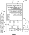
- Fig. 2 is a block diagram that illustrates a representative virtual assist apparatus 100 according to the example embodiments.
- the virtual assist apparatus 100 is suitable for executing embodiments of one or more software systems or logic modules that perform a virtual guidance method for assisting an operator of an associated work vehicle by providing verification of compatibility of implements and loads with loaders and/or tractors carrying the loaders, as well as by providing viewable images for assisting mutual coupling of loaders and implements and engagement of loads with the implements, and by further providing implement height and level detection for performing work functions with the implements including repeated work functions automatically.
- the representative virtual assist apparatus 100 comprises a guidance control apparatus 110 that includes a bus 202 or other communication mechanism for communicating information, and a processor device 204 coupled with the bus for processing information.
- the guidance control apparatus 110 further a main non-transitory memory device 210 that may comprise one or more memory portions or components or collection of other devices such as random access memory (RAM) 206 or other dynamic storage device for storing information and instructions to be executed by the processor device 204, and read only memory (ROM) 208 or other static storage device for storing static information and instructions for the processor device 204.
- RAM random access memory
- ROM read only memory
- the memory device 210 is also suitably provided for storing the virtual guidance logic 211 comprising instructions for execution by the processor, and other information including for example data and instructions for execution by the processor for obtaining and displaying visual aids on the screen 132 of the display unit 130 that is viewable from an operator's seat of the associated work vehicle 1.
- the visual aids are displayed for helping to guide the user in operating the loader to position a boom relative to the work vehicle, to position the boom and/or tool carrier relative to level ground, to position the tool carrier 22 on the free end 23 thereof relative to the one or more various attachments or implements 24 to be coupled with the carrier 22, to position the one or more various attachments or implements 24 relative to the boom and/or relative to the ground.
- the memory device 210 may further store implement compatibility verification logic 230 that is executable by the processor device 204 to determine a compatibility between the tool carrier and the associated implement to mutually couple the tool carrier with the implement, and generate implement compatibility data based on determining the compatibility between the tool carrier and the associated implement to mutually coupling the tool carrier with the implement, wherein the display unit is operable to display a viewable image of the implement compatibility data, based on the determining the compatibility for confirming to the operator the determined compatibility between the tool carrier and the associated implement.
- the memory device 210 may further store load compatibility verification logic 231 that is executable by the processor device 204 to determine a compatibility between the implement coupled with the tool carrier and the associated load to mutually engage the load with the implement, and generate load compatibility data based on determining the compatibility between the implement and the associated load to permit mutual engagement between the implement and the load, wherein the display unit is operable to display a viewable image of the load compatibility data, based on the determining the compatibility for confirming to the operator the determined compatibility between the implement and the associated load.
- load compatibility verification logic 231 that is executable by the processor device 204 to determine a compatibility between the implement coupled with the tool carrier and the associated load to mutually engage the load with the implement, and generate load compatibility data based on determining the compatibility between the implement and the associated load to permit mutual engagement between the implement and the load, wherein the display unit is operable to display a viewable image of the load compatibility data, based on the determining the compatibility for confirming to the operator the determined compatibility
- the memory device 210 may further store implement height and level detection and control logic 232 that is executable by the processor for performing work functions with the implements at selected and/or selectable heights and/or levels including for example repeated work functions in an automated fashion.
- the example embodiments described herein are related to the virtual assist apparatus or controller 100 performing a method providing visual aids that assist an operator of an associated work vehicle to maneuver a loader on a tractor relative to an associated target item such as an implement to couple the implement or other attachment onto a tool carrier of the loader, and to assist the operator maneuver the implement having been coupled with the loader relative to an associated workpiece for engaging the load item with the implement.
- information for the visual aids to be displayed on the screen of the display unit in the form herein of visual offset movement instructions and visual inclination movement instructions are provided by the virtual assist apparatus or controller 100 in response to the processor device 204 executing the virtual guidance logic 211 comprising one or more sequences of instructions of logic modules contained in main memory 206.
- Such instructions may be read into main memory 206 from another computer-readable medium, such as storage device 210.
- Execution of the sequences of the virtual guidance logic 211 instructions contained in storage device 210 and/or main memory 206 causes the processor device 204 to perform the process steps described herein.
- hard-wired circuitry may be used in place of or in combination with software instructions to implement the example embodiments.
- implementations of the example embodiments are not limited to any specific combination of hardware circuitry, software, logic, or combinations of hardware, software, and/or logic.
- Non-volatile media includes, for example, optical or magnetic disks.
- Volatile media includes dynamic memory for example and does not include transitory signals, carrier waves, or the like.
- Computer-readable media include, for example, a floppy disk, a flexible disk, hard disk, magnetic tape, or any other magnetic medium, a CD-ROM, any other optical medium, punch cards, papertape, any other physical medium with patterns of holes, a RAM, PROM, and EPROM, a FLASH-EPROM, any other memory chip or cartridge, or any other tangible non-transitory medium from which a computer can read.
- logic includes hardware, firmware, software in execution on a machine, and/or combinations of each to perform a function(s) or an action(s), and/or to cause a function or action from another logic, method, and/or system.
- Logic may include a software controlled microprocessor, a discrete logic (e.g., ASIC), an analog circuit, a digital circuit, a programmed logic device, a memory device containing instructions, and so on.
- Logic may include one or more gates, combinations of gates, or other circuit components.
- the virtual assist apparatus or controller 100 further includes a communication interface 218 coupled with the bus 202 which provides a two-way data communication coupling to a network link 220 that is connected to local network 212 such as for example a local network of the work vehicle 1 such as a Controller Area Network (CAN) bus or the like.
- the communication interface 218 may be a controller area network (CAN) card to provide a data communication connection to a compatible CAN bus.
- CAN controller area network
- communication interface 218 may be a local area network (LAN) card to provide a data communication connection to a compatible LAN.
- LAN local area network
- communication interface 218 may be an integrated services digital network (ISDN) card or a modem to provide a data communication connection to a corresponding type of telephone line.
- ISDN integrated services digital network
- Wireless links may also be implemented.
- communication interface 218 may be a wireless receiver/transmitter, i.e. a transceiver operable to send and receive electrical, electromagnetic, radio frequency (RF), and/or optical signals that carry data streams such as digital data streams representing various types of information.
- RF radio frequency
- Network link 220 typically provides data communication through one or more networks to other data devices.
- network link 220 may provide a connection through a local network to a diagnostic host computer (not shown) of the like for supporting configuration of the system as desired or necessary.
- An Internet Service Provider (ISP) 226 may provide data communication services indirectly through the Internet via the network 212 or directly through the network link 220.
- the example virtual assist apparatus or controller 100 can send messages and receive data, including program code, through the network(s), network link 220 and communication interface 218.
- the virtual assist apparatus or controller 100 is operatively connected with a plurality of external public, private, governmental or commercial servers (not shown) configured to execute a web application in accordance with example embodiments.
- the example virtual assist apparatus or controller 100 suitably includes several subsystems or modules to perform the virtual operator's guidance as set forth herein.
- a benefit of the subject application is to provide improved guidance by displaying offset and inclination movement guidance instructions on a screen 132 of a display unit 130 that is viewable from an operator's seat of the associated work vehicle for helping the operator to view current positions of the loader and tool mechanisms as well as to visualize preferred or recommended movements of the loader and tool carrier mechanisms to safely and efficiently couple the tool carrier with a tool to safely and efficiently attach the tool onto the tool carrier portion of the loader.
- An output device 215 may also be provided such as in the form of a sound generating device such as a speaker to help improve guidance assistance by generating audible guidance instructions in the form of audible instructions and/or suitable instructional noises such as beeps, voice messages or the like that can be heard from an operator's seat of the associated work vehicle for helping the operator to be alerted to current positions of the mechanisms as well as to be audibly instructed of preferred or recommended paths for movement of the loader and/or tool carrier mechanisms to safely and efficiently load, unload, or otherwise couple the desired implement 24 with the tool carrier 22, and also to handle the material using the implement 24 received onto the carrier 22.
- a sound generating device such as a speaker to help improve guidance assistance by generating audible guidance instructions in the form of audible instructions and/or suitable instructional noises such as beeps, voice messages or the like that can be heard from an operator's seat of the associated work vehicle for helping the operator to be alerted to current positions of the mechanisms as well as to be audibly instructed of preferred or
- the example embodiment of the virtual assist apparatus further includes an input device 214 operatively coupled with the guidance control apparatus.
- the input device 214 may be used during a training of the virtual assist apparatus for receiving a boom and tool carrier position training signal representative of the first predetermined target location alignment of the boom and tool carrier to establish a predetermined relative physical position between the tool carrier portion of the loader and a selected implement disposed on the ground adjacent to the associated work vehicle.
- the input device 214 may include a touchscreen portion 134 of the display unit 130, a pointer device 216 operatively coupled with the guidance control apparatus, or any other device or means of communicating training and other information to the control unit 110 of the virtual guidance assist apparatus 100.
- the operator may first position the boom 20 and tool carrier 22 to a desired position relative to the ground, then enter a command on the touchscreen 134 using a pointer or finger onto a selected portion of the menu image while the boom and tool carrier are in their desired positions, thereby identifying a boom position training signal representative of a selectable command on the screen for alignment of the boom and tool carrier to establish a desired relative physical position between the tool carrier and the implement relative to the ground.
- the desired relative physical position between the tool carrier and the implement relative to the ground may be represented as a desired height of the tool carrier and the implement relative to the ground, a desired level of the tool carrier and the implement relative to the ground, or both a desired height and level of the tool carrier and the implement relative to the ground.
- Fig. 3 is a flow diagram showing a method 300 of operating the subject virtual assist apparatus 100 in accordance with an example embodiment.
- the operator rough pre-positions the loader relative to a target item.
- the operator may operator may rough pre-position a tool carrier on an end of the loader relative to a target item comprising an implement such as for example, the pallet fork implement 27.
- the operator may operator may rough pre-position an implement having been coupled with the tool carrier of the loader relative to a target item comprising an associated load.
- the subject virtual assist apparatus 100 performs a compatibility verification.
- the virtual assist apparatus 100 may execute the implement compatibility verification logic 230 to determine a compatibility between the tool carrier on the loader and an implement comprising the target item.
- the virtual assist apparatus 100 may execute the load compatibility verification logic 231 to determine a compatibility between the tractor and/or the implement coupled with the tool carrier and an associated load.
- the virtual assist apparatus 100 may provide a warning to the operator of any incompatibilities as between the tool carrier and the target implement and/or as between the implement and the target load.
- the subject virtual assist apparatus 100 develops and displays operator assist images for assisting movement of a loader carried on a tractor to position the loader relative to an associated target item for mutually engaging the loader with the target.
- the virtual assist apparatus 100 may develop and display operator assist images for assisting movement of a tool carrier carried on a loader of a tractor to position the tool carrier relative to an associated implement target item for mutually coupling the tool carrier with the associated implement.
- the virtual assist apparatus 100 may develop and display operator assist images for assisting movement of an implement having been coupled with the tool carrier on a loader of a tractor to position the implement relative to an associated load target item for mutually engaging the implement with the associated load.
- the operator may operate the tractor using the operator assist images developed and displayed at 330 by the subject virtual assist apparatus 100 to move the tractor and/or loader carried on the tractor to position the loader relative to the associated target item for mutually engaging the loader with the target item.
- the operator moves the tractor and/or loader carried on the tractor to position a tool carrier of the loader relative to an associated implement item for mutually coupling the tool carrier with the implement.
- the operator moves the tractor and/or loader carried on the tractor to position a implement having been coupled with a tool carrier relative to an associated load for mutually engaging the load using the implement.
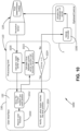
- the subject virtual assist apparatus 100 develops and displays operator assist images using vision-based implement level detection to assist an operator perform work functions.
- the subject virtual assist apparatus 100 develops and displays visual aids described herein that are provided to the operator of the associated work vehicle 1 for properly locating the tool carrier 22 on the free end 23 of the boom 20 at a desired height relative to the ground for training the system for RTP operation, and also for providing further visual aids for assisting in properly raising, lowering and/or tilting the tool carrier 22 to a desired orientation or inclination for enabling coupling of the carrier 22 with the selected attachment 24 and for engaging a load with an implement having been coupled with the loader, for training the system for the RTP operation, and further for positioning the work vehicle 1 relative to the selected implement 24 for moving the vehicle 1 supporting the tool carrier 22 into a coupling relationship with the selected implement 24 for mutually connecting the tool carrier 22 with the selected implement 24 and for mutually engaging a load with the implement, for training the system for the RTP operation.
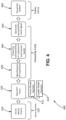
- Fig. 4 is a diagram showing a functional flow 400 of the virtual assist apparatus 100 verifying a compatibility between a loader 47 and a target item in accordance with an example embodiment.
- the virtual assist apparatus 100 verifies a compatibility between a loader 47 and a target item using deep learning.
- the virtual assist apparatus 100 verifies a compatibility between a tool carrier 22 of the loader 47 and a target item comprising an implement 24 using deep learning. It is to be appreciated however that in further embodiments the virtual assist apparatus 100 verifies a compatibility between an implement having been coupled with a tool carrier 22 and a target item comprising an associated load using deep learning.
- the processor is operable to execute the implement compatibility verification logic 230 in accordance with an example embodiment to determine, based on implement characteristic data and tool carrier characteristic data, a compatibility between the tool carrier and the associated implement to mutually couple the tool carrier with the implement.
- the virtual assist apparatus 100 provides assistance to an operator with regard to verification of interoperability of an implement with a tool carrier and/or of an implement with a tractor that carries the tool carrier on a boom prior to the attempted mutual coupling therebetween.
- the processor is further operable to execute the load compatibility verification logic 231 in accordance with an example embodiment to determine, based on load characteristic data and implement characteristic data, a compatibility between the implement and the associated load to mutually engage the load using the implement.
- the virtual assist apparatus 100 provides assistance to an operator with regard to verification of interoperability of a load with an implement and/or of a load with a tractor that carries the tool carrier and implement on a boom prior to the attempted mutual engage the load with the implement.
- an image of the implement is received.
- the image of the implement may be obtained using the imaging system 120.
- the imaging system 120 operates to generate work area image data representative of an image of a work area adjacent to the tractor, wherein the work area image data includes implement image data representative of an image of the associated implement disposed in the work area.
- an image of a load may equivalently be received.
- the image of the load may be obtained using the imaging system 120.
- the imaging system 120 operates to generate work area image data representative of an image of a work area adjacent to the tractor, wherein the work area image data includes load image data representative of an image of the associated load disposed in the work area.
- the information relating to the loader may be obtained from the operator of the tractor such as by the operator inputting data by making a selection of a menu item or by entering raw data using for example the touchscreen 134.
- the display device 130 may offer several menu items to the operator such as for example tractor model number 422 and loader model number 424.
- the operator may enter the tractor model number and the loader model number via empty field presentations provided on the touchscreen or the operator may be presented with selectable example tractor and loader model numbers having related data already stored in the memory device 210.
- the implement is identified.
- deep learning is used to identify the implement.
- the processor device is operable to execute a deep learning implement detection model 233 to automatically detect, based on the implement image data, the physical characteristic of the associated implement and store the detected physical characteristic of the associated implement in the memory device 210 as implement characteristic data for determining the compatibility between the tool carrier and the associated implement to mutually couple the tool carrier with the implement.
- the virtual guidance apparatus 100 is functional 300 to identify in general one or more attachment(s) of the implement, and to identify one or more attachment features such as hooks or the like on the attachment using the deep learning implement detection model 233.
- the camera device 121 is operable to generate the implement image data, wherein the implement image data comprises implement attachment feature data representative of an image of the implement attachment feature of the implement, and the processor 204 is operable to execute the logic 233 to automatically detect the implement as well as the attachment feature(s) of the implement relative to the camera device based on the implement attachment feature data of the implement image data, and to automatically generate, based on the automatically detected implement attachment feature, the implement characteristic data for use in determining the compatibility between the tool carrier and the associated implement to mutually couple the tool carrier with the implement.
- the implement image data comprises implement attachment feature data representative of an image of the implement attachment feature of the implement
- the processor 204 is operable to execute the logic 233 to automatically detect the implement as well as the attachment feature(s) of the implement relative to the camera device based on the implement attachment feature data of the implement image data, and to automatically generate, based on the automatically detected implement attachment feature, the implement characteristic data for use in determining the compatibility between the tool carrier and the associated implement to mutually couple the tool carrier with the implement
- the deep learning detection model may comprise, for example, a deep learning neural network for object detection including for example for detection of the one or more attachment features on the implement.
- the deep learning detection model may comprise, for example, a pre-build build model such as for example, Resnet, Mobilnet, InceptionV2, or the like.
- the associated load may be identified.
- deep learning is used to identify the load.
- the processor device is operable to execute a deep learning load detection model 234 to automatically detect, based on load image data, the physical characteristic of the associated load and store the detected physical characteristic of the associated load in the memory device 210 as load characteristic data for determining the compatibility between the implement and load to mutually engage the load with the implement.
- the virtual guidance apparatus 100 is functional 300 to identify in general one or more attachment(s) of the load, and to identify one or more load attachment features such as hooks or the like on the attachment using the deep learning load detection model 234.
- the processor 204 is operable to execute the logic 234 to automatically detect the load as well as the load attachment feature(s) based on load attachment feature data of the load image data, and to automatically generate, based on the automatically detected load attachment feature, the load characteristic data for use in determining the compatibility between the tractor and/or implement and the load to permit engagement of the load using the implement.
- the functional flow 400 of the virtual assist apparatus 100 may also verify compatibility between the load and the loader and/or the implement that was determined using the deep learning detection model.
- the processor device 204 is operable to execute the load compatibility verification logic 231 to determine, based on the load characteristic data obtained using the deep learning detection model and the load characteristic data such as from the operator for example, a compatibility between the implement and the load to permit engagement of the load using the implement.
- the functional flow 400 of the virtual assist apparatus 100 generates a compatibility check signal such as for example implement compatibility data based on determining the compatibility between the tool carrier and the associated implement to mutually coupling the tool carrier with the implement.
- the virtual assist apparatus 100 generates a load compatibility check signal based on determining the compatibility between the associated load and the implement to permit engaging the load with the implement.
- the functional flow 400 of the virtual assist apparatus 100 displays the result of the compatibility check on as visual aid device such as for example on the display unit 130.
- the display unit is operable to display a viewable image of the implement compatibility data, based on the determining the compatibility for confirming to the operator the determined compatibility between the tool carrier and the associated implement.
- Fig. 5 is a functional block diagram showing the virtual assist apparatus 100 in accordance with an example embodiment.
- the virtual assist apparatus 100 includes a guidance control apparatus 110, an imaging system 120 in the form in the example of an image sensor device 121, and a display unit 130 including a screen 132 that is viewable by an operator of the tractor.
- the imaging system 120 is operable to generate work area image data that includes loader image data such as tool carrier image data representative of an image of the tool carrier 22 and target item image data such as implement image data representative of an image of the associated implement 24 disposed in the work area adjacent to the tractor.
- the target item image data may include load image data representative of an image of an associated load in the work area.
- the virtual assist apparatus 100 is operable in the functional block 500 to identify 510 an attachment such as an implement for example, and to identify 520 one or more attachment features such as hooks or the like on the attachment.
- the identification functional block 500 is also operative to identify one or more attachment features such as hooks or the like on the tool carrier that are selectively couplable with the attachment features of the attachment such as for example one or more attachment features of an implement.
- the virtual assist apparatus 100 is functional to generate 540 one or more align assist signals for assisting movement of a loader carried on an associated tractor for connection of a tool carrier of the loader with an attachment such as for example for connection of a tool carrier of the loader with an implement.
- the virtual assist apparatus 100 is functional to generate one or more align assist signals for assisting movement of an attachment such as an implement having been coupled with a tool carrier of a loader carried on an associated tractor for engagement of the implement with an associated load such as for example to place loads over or on implements.
- the processor device 204 is operable in the function 500 to execute virtual guidance logic stored in the memory device 210 based on the work area image data to generate heading data and implement alignment guidance data, wherein the heading data is representative of a heading of the tool carrier, and the implement alignment guidance data is representative of an implement approach path providing access to an implement attachment feature of the implement that is mutually coupleable with a corresponding carrier attachment feature of the tool carrier.
- the generated heading data and implement alignment guidance data may comprise tractor heading data representative of a heading of the tractor and load alignment guidance data representative of an approach path providing access to an engagement feature of a load that is mutually engageable with a corresponding feature of an implement coupled with the tool carrier.
- the display unit 130 is operable to display on the screen 132, based on the work area image data, the implement alignment guidance data, and the heading data, viewable images of the heading and the implement approach path in a viewable image of the work area, for assisting the movement of the loader to position the tool carrier relative to an associated implement for mutually coupling the tool carrier with the implement.
- the processor is operable to execute the virtual guidance logic to generate the alignment guidance data based on the implement image data and to generate the heading data based on the tool carrier image data
- the display unit is operable to display, based on the implement image data and the alignment guidance data, the viewable image of the implement approach path superimposed on a viewable image of the implement displayed on the screen.
- the display unit is operable to display, based on the implement image data and the alignment guidance data, the viewable image of the implement approach path as one or more viewable approach path ray images extending from the viewable image of the implement displayed on the screen.
- the display unit is operable to display, based on the tool carrier image data and the heading data, the viewable image of the heading as one or more viewable heading ray images extending from the viewable image of the tool carrier displayed on the screen.
- the viewable image of the implement approach path is displayed as one or more viewable approach path ray images extending perpendicularly from an imaginary plane defined by a front of the viewable image of the implement.
- the viewable image of the heading is displayed as one or more viewable heading ray images extending perpendicularly from an imaginary plane defined by a front of the viewable image of the tool carrier.
- the methods and systems herein assist an operator to visualize and align portions of a tool carrier of a tractor relative to a material handling attachment such as an implement intended to be detachably coupled with the tool carrier, and to help visualize the position of one or more attachments on the tool carrier, such as to assist in properly approaching the implement to mutually couple the implement and the tool carrier.
- the operator physically repostionining the tractor relative to the implement in order to realize an alignment on the screen of the one or more viewable approach path ray images displayed on the screen with the one or more viewable heading ray images displayed on the screen establishes a physical alignment between the carrier attachment feature of the tool carrier and the implement attachment feature of the implement for pre-staging mutual coupling therebetween.
- the operator may move the associated tractor about a yaw axis of the tractor by steering it to the left or right while driving the tractor forwards or backwards.
- These operator actions establish a physical repositioning of the tool carrier relative to the implement as prescribed by the alignment goal on the screen between the one or more viewable approach path ray images with the one or more viewable heading ray images to thereby establish an alignment between the carrier attachment feature of the tool carrier and the implement attachment feature of the implement for pre-staging mutual coupling therebetween.
- the virtual assist apparatus 100 is functional 500 to identify 510 an attachment, and to identify 520 one or more attachment features such as hooks or the like on the attachment using a deep learning detection model 233.
- the image sensor device 121 is operable to generate the implement image data, wherein the implement image data comprises implement attachment feature data representative of an image of the implement attachment feature of the implement, and the processor device 204 is operable to execute the logic 233 to automatically detect the implement attachment feature of the implement relative to the image sensor device based on the implement attachment feature data of the implement image data, and to automatically generate, based on the automatically detected implement attachment feature, the alignment guidance data representative of the incremental movement for moving the loader relative to the implement for mutually coupling the carrier and implement attachment features.
- the logic 211 stored in the memory device 210 comprises a deep learning detection model 233, and the processor device 204 is operable to execute the deep learning detection model to automatically detect the implement attachment feature of the implement relative to the vision device based on the implement attachment feature data of the implement image data.
- the virtual assist apparatus 100 is functional 500 to identify 510 an attachment, and to identify 520 one or more attachment features such as hooks or the like on the attachment using a functional operation 532 to receive a selection from an operator of attachment information from a database stored in the memory device 210.
- the guidance control apparatus in this example embodiment includes an implement database stored in the memory device, wherein the implement database includes a first implement data set correlating a first implement type of a first implement with first attachment feature location data representative of one or more locations of one or more physical implement attachment features of the first implement, and a second implement data set correlating a second implement type of a second implement with second attachment feature location data representative of one or more locations of one or more physical implement attachment features of the second implement.
- the guidance control apparatus is operable to receive an implement identification signal, wherein the implement identification signal being representative of an identity of the implement.
- the processor is operable to execute the logic to select, based on the implement identification signal corresponding to a one of the first or second implement types, a corresponding one of the first or second implement data sets from the implement database, and to automatically generate, based on the implement image data and on the first or second attachment feature location data corresponding to the selected one of the first or second implement data sets, the alignment guidance data representative of the incremental movement for moving the loader relative to the implement for mutually coupling the carrier and implement attachment features.
- the input device 214 may include a touchscreen portion 134 of the display unit 130, a pointer device 216 operatively coupled with the guidance control apparatus, or any other device or means of communicating training and other information to the control unit 110 of the virtual guidance assist apparatus 100.
- the operator interface is operable to receive an implement selection signal from an operator of the tractor, and to generate the implement identification signal corresponding to the received implement selection signal.
- the selection of information from the database is made based on signage carried on the implement.
- the processor is operable to execute the logic to detect, based on the implement image data, identification indicia carried on the implement, and to determine the detected indicia being representative of a one of the first or second implement types.
- the logic is further executable to select, based on the detected indicia being determined to be representative of a one of the first or second implement types, a corresponding one of the first or second implement data sets from the implement database, and to automatically generate, based on the implement image data and on the first or second attachment feature location data corresponding to the selected one of the first or second implement data sets, the alignment guidance data representative of the incremental movement for moving the loader relative to the implement for mutually coupling the carrier and implement attachment features.
- the virtual assist apparatus 100 is functional 500 to identify 510 an attachment, and to identify 520 one or more attachment features such as hooks or the like on the attachment using an automatic selection 534 based on information received into the guidance control apparatus 110 and obtained from information contained on signage carried on the associated implement.
- the signage may comprise a bar code, a QR code, or the like, or any signage that may embed information into markings formed by the signage.
- the processor is operable to execute the logic to detect, based on the implement image data, implement information indicia carried on the implement, and to determine, based on detecting the implement information indicia, attachment feature location data representative of one or more locations of one or more physical implement attachment features of the implement.
- the processor is operable to execute the logic to automatically generate, based on the implement image data and on the attachment feature location data, the alignment guidance data representative of the incremental movement for moving the loader relative to the implement for mutually coupling the carrier and implement attachment features.
- Fig. 6 is a perspective view of a physical work environment 600 that includes a tractor 2 and a target item 50 represented in the Figure as an implement 24 spaced from and adjacent to the tractor 2 in the work area.
- the showings of Fig. 6 are useful for illustrating the relationship between the virtual guidance information provided to the vehicle operator by the systems and methods of the present disclosure and the physical work area and equipment disposed in the work area.
- the processor 204 is operable to execute the virtual guidance logic 211 to generate, based on work area image data, tractor heading data representative of a tractor heading of the tractor, and target alignment guidance data representative of a target approach path providing access to a target attachment feature of the target that is mutually engageable with a corresponding loader attachment feature of the loader.
- the display unit 130 is operable to display, based on the work area image data, the target alignment guidance data, and the tractor heading data, a viewable tractor heading image 52 representative of the determined tractor heading and a target approach path image 54 representative of the determined target approach path.
- the tractor heading and target approach path images 52, 54 are displayed in a viewable image of the work area, for assisting the movement of the tractor to position the loader relative to the associated target item 50 for mutually engaging the loader with the associated target item 50.
- the tractor heading image 52 is displayed as an intermittent set of one or more non-continuous lines that turn persistent and solid to indicate proper alignment to/with the target approach path image 54.
- the target approach path image 54 may be displayed as an intermittent set of one or more non-continuous lines that turn persistent and solid to indicate proper alignment to/with the tractor heading image 52.
- the processor 204 is operable to execute the virtual guidance logic 211 to generate heading data and implement guidance data based on work area image data generated by the imaging system.
- the heading data is representative of a heading of the physical tool carrier 22 on the loader 10 of the tractor 2
- the implement alignment guidance data is representative of an implement approach path providing access to an implement attachment feature of the implement 24 that is mutually coupleable with a corresponding carrier attachment feature of the tool carrier 22.
- the display unit 130 is operable to display, based on the work area image data, the implement alignment guidance data of the work area image data, and the heading data of the work area image data, a viewable image 610 of the heading of the tool carrier, and a viewable image 620 of the implement approach path.
- the heading and implement approach path viewable images 610, 620 are displayed in a viewable image 602 of the work area, for assisting the movement of the loader to position the tool carrier relative to an associated implement for mutually coupling the tool carrier with the implement.
- the viewable image 620 of the implement approach path is displayed as an intermittent set of one or more non-continuous lines that turn persistent and solid to indicate proper alignment to/with the viewable image 610 of the heading of the tool carrier.
- the viewable image 610 of the heading of the tool carrier may be displayed as an intermittent set of one or more non-continuous lines that turn persistent and solid to indicate proper alignment to/with the viewable image 620 of the implement approach path.
- the operator need only steer the tractor towards the implement in a manner to realize an overlay or coincidence between the viewable image 610 of the heading of the tool carrier, and the viewable image 620 of the implement approach path.
- the operator By lining up the viewable image 610 of the heading of the tool carrier with the a viewable image 620 of the implement approach path with the tractor spaced from the implement and prior to moving the tractor towards the implement, the operator is ensured that the carrier attachment feature of the tool carrier will be brought towards the implement attachment feature of the implement along an implement approach path that provides access to the implement attachment feature of the implement. In that way, the tool carrier and the implement may be mutually coupled.
- Fig. 7 is an illustration showing an image 700 of viewable guidance images displayed on a screen 132 of a display unit 130 for assisting an operator move a tractor carrying a loader relative to an associated target item in the form in the illustrated example of an implement for pre-coupling the implement with the loader.
- the display unit 130 is operable to display, based on the work area image data, the implement alignment guidance data, and the heading data, a viewable image 610 of the heading of the tractor or carrier, and a viewable image 620 of the implement approach path in a viewable image 702 of the work area, for assisting the movement of the loader to position the tool carrier relative to an associated implement for pre-coupling the implement with the loader.
- the display unit 130 is operable to display, based on implement image data and alignment guidance data generated by the processor executing virtual guidance logic, the viewable image 620 of the implement approach path superimposed on a viewable image 704 of the implement displayed on the screen.
- the display unit 130 is operable to display, based on tool carrier image data and heading data generated by the processor executing virtual guidance logic, the viewable image 610 of the heading superimposed on a viewable image 706 of the tool carrier displayed on the screen.
- the viewable image 620 of the implement approach path is displayed as an intermittent set of one or more non-continuous lines that turn persistent and solid to indicate proper alignment to/with the viewable image 610 of the heading of the tool carrier.
- the viewable image 610 of the heading of the tool carrier may be displayed as an intermittent set of one or more non-continuous lines that turn persistent and solid to indicate proper alignment to/with the viewable image 620 of the implement approach path.
- the processor device 204 is operable to execute the virtual guidance logic 211 to generate approach path ray data based on the alignment guidance data, and heading ray data based on the heading data.
- the display unit is operable to display, based on the implement image data and the approach path ray data, the viewable image of the implement approach path 620 as one or more viewable approach path ray images 622, 624 extending from the viewable image of the implement 704 displayed on the screen.
- the display unit 130 is further operable to display, based on the tool carrier image data and the heading ray data, the viewable image of the heading as one or more viewable heading ray images 612, 614 extending from the viewable image of the tool carrier 706 displayed on the screen.
- an alignment on the screen of the one or more viewable approach path ray images 622, 624 displayed on the screen with the one or more viewable heading ray images 612, 614 displayed on the screen by the operator moving the associated tractor about a yaw axis (the Y-axis Fig. 1 ) of the tractor relative to the implement establishes an alignment between the carrier attachment feature of the tool carrier and the implement attachment feature of the implement for pre-staging mutual coupling therebetween.
- the one or more viewable approach path ray images 622, 624 are displayed as an intermittent set of one or more non-continuous lines that turn persistent and solid to indicate proper alignment to/with the one or more viewable heading ray images 612, 614.
- the one or more viewable heading ray images 612, 614 may be displayed as an intermittent set of one or more non-continuous lines that turn persistent and solid to indicate proper alignment to/with the one or more viewable approach path ray images 622, 624.
- the processor device 204 is operable to execute the virtual guidance logic 211 to generate implement connection completion target indicia data based on the alignment guidance data and the approach path ray data, and carrier connection completion target indicia data based on the heading data and the heading ray data.
- the display unit of the virtual assist apparatus is operable to display, based on the implement image data and the implement connection completion target indicia data, a viewable implement connection completion target indicia image 626 defining a position along the one or more viewable approach path ray images 622, 624 representative of an implement connection completion confirmation.
- the display unit is operable to display, based on the tool carrier image data and the carrier connection completion target indicia data, a viewable carrier connection completion target indicia image 616 defining a position along the one or more viewable heading ray images 612, 614 representative of a tool carrier connection completion confirmation.
- the implement connection completion target indicia image 626 may be displayed as an intermittent set of one or more non-continuous shapes or forms such as circles as shown or lines that turn persistent and solid to indicate proper alignment to/with the carrier connection completion target indicia image 616.
- the carrier connection completion target indicia image 616 may be displayed as an intermittent set of one or more non-continuous shapes or forms such as circles as shown or lines that turn persistent and solid to indicate proper alignment to/with the implement connection completion target indicia image 626.
- the implement attachment feature of the implement is far from being mutually coupleable with a corresponding carrier attachment feature of the tool carrier.
- the physical attachment features are spaced apart as indicated by the distance between the one or more viewable carrier connection completion target indicia image 616 and the display screen with the one or more viewable implement connection completion target indicia image 626.
- a coincidence on the screen of the viewable implement connection completion target indicia image displayed on the screen with the viewable tool carrier connection completion target indicia image displayed on the screen by the operator moving the tool carrier carried on the loader of the associated tractor towards the implement is representative of a confirmation of the mutual coupling between the carrier attachment feature of the tool carrier with the implement attachment feature of the associated implement.
- Fig. 8 is an illustration showing an image 800 of viewable guidance images displayed on a screen 132 of a display unit 130 for assisting an operator move a tractor carrying a loader relative to an implement for completing coupling the implement with the loader.
- FIG. 8 there is alignment on the screen of the one or more viewable approach path ray images 622, 624 with the one or more viewable heading ray images 612, 614. Accordingly, the operator has successfully moved the associated tractor about the yaw axis (the Y-axis Fig. 1 ) of the tractor relative to the implement in order to establish the alignment between the carrier attachment feature of the tool carrier and the implement attachment feature of the implement for completing the mutual coupling therebetween.
- the implement attachment feature of the implement is confirmed to be mutually coupleable with the corresponding carrier attachment feature of the tool carrier.
- the physical attachment features are mutually coupled as indicated by the coincidence in the images on the screen between the one or more viewable carrier connection completion target indicia image 616 and the display screen with the one or more viewable implement connection completion target indicia image 626.
- Fig. 9 is an illustration showing an image 900 of viewable guidance images displayed on a display unit for assisting an operator move a tractor carrying an implement coupled with a tool carrier of a loader relative to a target item in the form of a load for pre-engaging with the load using the implement.
- the display unit 130 is operable to display, based on the work area image data, the implement alignment guidance data, and the heading data, a viewable image 910 of the implement heading of an implement coupled with a tool carrier of the loader of the tractor, and a viewable image 920 of the load approach path in a viewable image of the work area, for assisting the movement of the implement on the loader to position the implement relative to an associated target item in the form of a load for engaging the load using the implement.
- the display unit 130 is operable to display, based on load image data and alignment guidance data generated by the processor executing virtual guidance logic, the viewable image 920 of the load approach path superimposed on a viewable image of the load displayed on the screen.
- the display unit 130 is operable to display, based on implement image data and heading data generated by the processor executing virtual guidance logic, the viewable image 910 of the heading superimposed on a viewable image of the implement displayed on the screen.
- the viewable image 920 of the load approach path is displayed as an intermittent set of one or more non-continuous lines that turn persistent and solid to indicate proper alignment to/with the viewable image 910 of the implement heading.
- the viewable image 910 of the implement heading may be displayed as an intermittent set of one or more non-continuous lines that turn persistent and solid to indicate proper alignment to/with the viewable image 920 of the load approach path.
- the processor device 204 is operable to execute the virtual guidance logic 211 to generate approach path ray data based on the alignment guidance data, and heading ray data based on the heading data.
- the display unit is operable to display, based on the implement image data and the approach path ray data, the viewable image of the implement approach path 920 as one or more viewable approach path ray images 922, 924 extending from the viewable image of the load displayed on the screen.
- the display unit 130 is further operable to display, based on the implement image data and the heading ray data, the viewable image of the implement heading as one or more viewable implement heading ray images 912, 914 extending from the viewable image of the load displayed on the screen.
- an alignment on the screen of the one or more viewable load approach path ray images 922, 924 is displayed on the screen with the one or more viewable implement heading ray images 912, 914 displayed on the screen by the operator moving the associated tractor about a yaw axis (the Y-axis Fig. 1 ) of the tractor relative to the implement establishes an alignment between the carrier attachment feature of the tool carrier and the implement attachment feature of the implement for pre-staging mutual coupling therebetween.
- the one or more viewable load approach path ray images 922, 924 are displayed as an intermittent set of one or more non-continuous lines that turn persistent and solid to indicate proper alignment to/with the one or more viewable implement heading ray images 912, 914.
- the one or more viewable implement heading ray images 912, 914 may be displayed as an intermittent set of one or more non-continuous lines that turn persistent and solid to indicate proper alignment to/with the one or more viewable load approach path ray images 922, 924.
- the processor device 204 is operable to execute the virtual guidance logic 211 to generate implement connection completion target indicia data based on the alignment guidance data and the approach path ray data.
- the processor device 204 is further operable to execute the virtual guidance logic 211 to generate carrier connection completion target indicia data based on the heading data and the heading ray data.
- the processor device 204 is still further operable to execute the virtual guidance logic 211 to generate load engagement completion or placement completion target indicia data based on the load alignment guidance data and the load approach path ray data.
- the display unit of the virtual assist apparatus is operable to display, based on the load image data and the load engagement or placement completion target indicia data, a viewable load placement completion target indicia image 926 defining a position along the one or more viewable approach path ray images 922, 924 representative of a load placement completion confirmation.
- the display unit is operable to display, based on the implement image data and the implement connection completion target indicia data, a viewable implement connection completion target indicia image 916 defining a position along the one or more viewable heading ray images 912, 914 representative of an implement connection completion confirmation.
- the load placement completion target indicia image 926 may be displayed as an intermittent set of one or more non-continuous shapes or forms such as a rectangle as shown or lines that turn persistent and solid to indicate proper alignment to/with the implement connection completion target indicia image 916.
- connection completion target indicia image 916 may be displayed as an intermittent set of one or more non-continuous shapes or forms such as a rectangle as shown or lines that turn persistent and solid to indicate proper alignment to/with the load placement completion target indicia image 926.
- Fig. 9 there is no alignment on the screen of the one or more viewable approach path ray images 922, 924 with the one or more viewable heading ray images 912, 914. Accordingly, the operator must move the associated tractor about the yaw axis (the Y-axis Fig. 1 ) of the tractor relative to the implement in order to establish an alignment between the carrier attachment feature of the tool carrier and the implement attachment feature of the implement for pre-staging mutual coupling therebetween. The operator must also move the loader such as to lower the boom arms or the like.
- the load engagement feature of the load is far from being mutually coupleable with a corresponding engagement feature of the implement.
- the physical attachment features are spaced apart as indicated by the distance between the one or more viewable implement connection completion target indicia image 916 and the display screen with the one or more viewable load placement completion target indicia image 926.
- the display unit is operable to display, based on the load image data and the load placement completion target indicia data, a viewable load placement completion target indicia image defining a position along the one or more viewable load approach path ray images representative of a load placement completion confirmation, and the display unit is further operable to display, based on the implement image data and the implement connection completion target indicia data, a viewable implement engagement completion target indicia image defining a position along the one or more viewable implement heading ray images representative of an implement engagement completion confirmation, wherein a coincidence on the screen of the viewable load placement completion target indicia image displayed on the screen with the viewable implement engagement completion target indicia image displayed on the screen by the operator moving the implement carried on the tool carrier of the loader of the associated tractor towards the load is representative of a confirmation of the mutual engagement between the implement attachment feature of the implement with the load placement feature of the associated implement.
- Fig. 10 illustrates a functional flow 1000 that provides implement height and level detection and control for performing work functions with the implements.
- Examiner embodiments herein are directed to methods and systems assisting an operator with implement height and level detection for performing work functions with the implements, including repeated work functions.
- the virtual assist apparatus 100 provides assistance to an operator with regard to implement height and level detection for performing work functions with the implements, including repeated work functions, and training the system for return to position (RTP) operation or the like.
- the virtual assist apparatus 100 may function in an RTP mode to automatically return the boom 20 overall, portions of the boom 20 such as for example the lift arms 36, 38 and/or the implement arms 46, 48, the various attachments, tools or implements 24 when so carried on the tool carrier 22, to one or more pre-stored position(s) in response to operator input.
- the functional flow 1000 of the example embodiment providing implement height and level detection and control for performing work functions with the implements is advantageous relative to prior mechanical implement level indicators that are relatively inaccurate since their use is highly dependent on operator efficiency as operator needs to continuously monitor the level indicator rod which is a painful task while performing loader operations.
- Vision based implement Level Indicator uses a perception sensor which will give the information about current implement level and it will be compared with reference value (e.g. ground plane) provided by the operator to generate error signal. Knowing the implement level will certainly be beneficial for operator to manually take corrective action.
- an automatic control can be provided using a controller which will act upon the error signal mentioned above to generate necessary corrective commands to quickly and accurately level the implement. This will also result in enhanced safety and work efficiency while operating the loader in automatic implement level control mode.
- the example virtual guidance apparatus or controller 100 can send messages and receive data, including program code, through the network(s), network link 220 and communication interface 218.
- the virtual guidance apparatus or controller 100 is operatively connected with a plurality of external public, private, governmental or commercial servers (not shown) configured to execute a web application in accordance with example embodiments.
- the example virtual guidance apparatus or controller 100 suitably includes several subsystems or modules to perform the virtual operator's guidance as set forth herein.
- a benefit of the subject application is to provide improved guidance by displaying offset and inclination movement guidance instructions on a screen 132 of a display unit 130 that is viewable from an operator's seat of the associated work vehicle for helping the operator to view current positions of the loader and tool mechanisms as well as to visualize preferred or recommended movements of the loader and tool carrier mechanisms to safely and efficiently couple the tool carrier with a tool to safely and efficiently attach the tool onto the tool carrier portion of the loader.
- An output device 215 may also be provided such as in the form of a sound generating device such as a speaker to help improve guidance assistance by generating audible guidance instructions in the form of audible instructions and/or suitable instructional noises such as beeps, voice messages or the like that can be heard from an operator's seat of the associated work vehicle for helping the operator to be alerted to current positions of the mechanisms as well as to be audibly instructed of preferred or recommended paths for movement of the loader and/or tool carrier mechanisms to safely and efficiently load, unload, or otherwise couple the desired implement 24 with the tool carrier 22, and also to handle the material using the implement 24 received onto the carrier 22.
- a sound generating device such as a speaker to help improve guidance assistance by generating audible guidance instructions in the form of audible instructions and/or suitable instructional noises such as beeps, voice messages or the like that can be heard from an operator's seat of the associated work vehicle for helping the operator to be alerted to current positions of the mechanisms as well as to be audibly instructed of preferred or
- the example embodiment of the virtual guidance apparatus further includes an input device 214 operatively coupled with the guidance control unit.
- the input device 214 may be used during a training of the virtual guidance apparatus for receiving a boom and tool carrier level position training signal representative of the first predetermined target location alignment of the boom and tool carrier to establish a predetermined relative physical position between the implement carried on the tool carrier portion of the loader and the ground.
- the input device 214 may include a touchscreen portion 134 of the display unit 130, a pointer device 216 operatively coupled with the guidance control unit, or any other device or means of communicating training and other information to the control unit 110 of the virtual guidance assist apparatus 100.
- the operator may first position the boom 20 and tool carrier 22 carrying an implement to a desired position that is level relative to the ground, then select a virtual level set point selection indicia that is displayed on the touchscreen 134 using a pointer or finger while the boom, tool carrier, and implement are in a desired position to dispose the implement level relative to the ground.
- the operator may position the tool carrier 22 in a desired position relative to the boom 20, then drag and drop the virtual indicia movable on the touchscreen 134 onto a selected portion of the image of boom on the screen 132 while the tool carrier 22 is in a desired position relative to the boom 20, wherein the virtual indicia comprises the carrier position training signal representative of a selectable target location on the screen for alignment of the carrier target device in the viewable image of the loader to establish a desired relative physical position between the carrier portion of the boom and the vehicle, the ground supporting the associated work vehicle, and/or relative to the boom 20.
- the virtual indicia may be a crosshair for example.
- the virtual indicia may be a visual symbol such as a logo, for example.
- the virtual indicia may be a static image capture of the tool carrier 22 disposed in the desired position relative to the boom 20.
- the operator moves the implement carried on the loader to a desired level position relative to the ground supporting the tractor.
- the optical system 120 receives an image of the loader and implement while the implement carried on the loader is held in the desired level position relative to the ground supporting the tractor. In this position, the operator may then select a virtual level set point selection indicia 1010 that is displayed on the touchscreen 134 using a pointer or finger while the boom, tool carrier, and implement are held in the desired position to dispose the implement level relative to the ground.
- the image of the loader and implement is thereby captured by the optical system 120 and stored as implement level set point data in the memory device 210 of the guidance control apparatus 110.
- the implement level set point data is displayed on the screen 132 as a loader image 1012.
- the operator may move the loader and implement carried thereon using standard tractor control mechanisms, etc.
- the operator may select a level command indicia displayed on the screen 132 whereupon the processor of the guidance control apparatus 110 may execute the level and height logic 232 to calculate a loader carrier angle at 1020 and deliver the image data received from the optical system 120 to the display unit 130 for display at 1012 together with a display of the loader and implement set in the desired level position.
- the pair of loader and implement images may be displayed, for example, as mutual overlays for visualization by the tractor operator.
- the processor of the guidance control apparatus 110 may further execute the level and height logic 232 to calculate at 1022 an error at 1022 between the current carrier position and the desired recorded carrier position.
- the user is notified at 1014 that the loader is at the desired position to realize the level between the implement and the ground.
- the virtual assist apparatus or controller 100 includes a communication interface 218 ( Fig. 2 ) coupled with the bus 202 that provides a two-way data communication coupling to a network link 220 that is connected to local network 212 such as for example a local network of the work vehicle 1 such as a Controller Area Network (CAN) bus or the like.
- the communication interface 218 may be a controller area network (CAN) card to provide a data communication connection to a compatible CAN bus.
- communication interface 218 may be a local area network (LAN) card to provide a data communication connection to a compatible LAN of the vehicle 2.
- the vehicle controller 1030 may react to the level control signal to actuate the one or more controlled devices of the tractor such as for example the lift cylinders 37, 39 coupled between the aft bracket set 30 and the mid bracket set 34 and/or the bucket cylinders 47, 49 coupled between the mid bracket set 34 and the forward bracket set 33 in order to move the loader and tool carrier to locate the implement in the desired level position.
- the one or more controlled devices of the tractor such as for example the lift cylinders 37, 39 coupled between the aft bracket set 30 and the mid bracket set 34 and/or the bucket cylinders 47, 49 coupled between the mid bracket set 34 and the forward bracket set 33 in order to move the loader and tool carrier to locate the implement in the desired level position.
Landscapes
- Engineering & Computer Science (AREA)
- Mechanical Engineering (AREA)
- Structural Engineering (AREA)
- Mining & Mineral Resources (AREA)
- Civil Engineering (AREA)
- General Engineering & Computer Science (AREA)
- Physics & Mathematics (AREA)
- Life Sciences & Earth Sciences (AREA)
- Optics & Photonics (AREA)
- Electromagnetism (AREA)
- Acoustics & Sound (AREA)
- Environmental Sciences (AREA)
- Soil Sciences (AREA)
- Computer Vision & Pattern Recognition (AREA)
- Remote Sensing (AREA)
- General Physics & Mathematics (AREA)
- Automation & Control Theory (AREA)
- Radar, Positioning & Navigation (AREA)
- Aviation & Aerospace Engineering (AREA)
- Multimedia (AREA)
- Component Parts Of Construction Machinery (AREA)
- Operation Control Of Excavators (AREA)
Applications Claiming Priority (1)
| Application Number | Priority Date | Filing Date | Title |
|---|---|---|---|
| US18/356,552 US20250024772A1 (en) | 2023-07-21 | 2023-07-21 | System and method providing load and implement verification |
Publications (1)
| Publication Number | Publication Date |
|---|---|
| EP4495331A1 true EP4495331A1 (de) | 2025-01-22 |
Family
ID=91782256
Family Applications (1)
| Application Number | Title | Priority Date | Filing Date |
|---|---|---|---|
| EP24185862.0A Pending EP4495331A1 (de) | 2023-07-21 | 2024-07-02 | Ein virtuelles hilfsgerät zur unterstützung des gegenseitigen eingriffs eines ladegeräts mit einem zielobjekt |
Country Status (3)
| Country | Link |
|---|---|
| US (1) | US20250024772A1 (de) |
| EP (1) | EP4495331A1 (de) |
| CA (1) | CA3243617A1 (de) |
Citations (3)
| Publication number | Priority date | Publication date | Assignee | Title |
|---|---|---|---|---|
| US20210127550A1 (en) * | 2019-10-31 | 2021-05-06 | Deere And Company | Vehicle attachment carrier loading guidance |
| EP4086392A1 (de) * | 2021-04-14 | 2022-11-09 | Deere & Company | System und verfahren zum bereitstellen visueller hilfsmittel zum positionieren eines werkstückmanipulators und zur vorschau der bewegungsbahn |
| EP4265849A1 (de) * | 2022-04-20 | 2023-10-25 | Deere & Company | System und verfahren zur bereitstellung von überlagerungen zur unterstützung der kopplung von ladern mit anbaugeräten |
Family Cites Families (1)
| Publication number | Priority date | Publication date | Assignee | Title |
|---|---|---|---|---|
| JP7435532B2 (ja) * | 2021-04-20 | 2024-02-21 | トヨタ自動車株式会社 | スロープ搭載車両 |
-
2023
- 2023-07-21 US US18/356,552 patent/US20250024772A1/en active Pending
-
2024
- 2024-06-20 CA CA3243617A patent/CA3243617A1/en active Pending
- 2024-07-02 EP EP24185862.0A patent/EP4495331A1/de active Pending
Patent Citations (3)
| Publication number | Priority date | Publication date | Assignee | Title |
|---|---|---|---|---|
| US20210127550A1 (en) * | 2019-10-31 | 2021-05-06 | Deere And Company | Vehicle attachment carrier loading guidance |
| EP4086392A1 (de) * | 2021-04-14 | 2022-11-09 | Deere & Company | System und verfahren zum bereitstellen visueller hilfsmittel zum positionieren eines werkstückmanipulators und zur vorschau der bewegungsbahn |
| EP4265849A1 (de) * | 2022-04-20 | 2023-10-25 | Deere & Company | System und verfahren zur bereitstellung von überlagerungen zur unterstützung der kopplung von ladern mit anbaugeräten |
Also Published As
| Publication number | Publication date |
|---|---|
| CA3243617A1 (en) | 2025-06-02 |
| US20250024772A1 (en) | 2025-01-23 |
Similar Documents
| Publication | Publication Date | Title |
|---|---|---|
| US12122296B2 (en) | System and method providing visual aids for workpiece manipulator positioning and movement preview path | |
| US12146299B2 (en) | System and method providing overlays for assisting coupling loaders with implements | |
| US20140111648A1 (en) | Device For Monitoring Area Around Working Machine | |
| EP3730704B1 (de) | Baumaschine | |
| EP3739131B1 (de) | Baumaschine | |
| JP3827480B2 (ja) | 自動運転建設機械およびその位置計測手段の校正方法 | |
| CN114859768A (zh) | 用于包括工具的工程机械的远程操作的系统和方法 | |
| US12448756B2 (en) | Vehicle vision | |
| JP2016079677A (ja) | 領域制限掘削制御装置及び建設機械 | |
| EP4050166B1 (de) | Maschinenführungsprogramm und bagger, der dieses verwendet | |
| US20250024772A1 (en) | System and method providing load and implement verification | |
| US12606089B2 (en) | Method and apparatus for loader positioning and load handling using vision system | |
| JP2025123500A (ja) | 作業エリア設定システム | |
| JP2025038550A (ja) | 作業システム | |
| US20230056724A1 (en) | Remote operation device, remote operation assistance server, remote operation assistance system, and remote operation assistance method | |
| EP4495330B1 (de) | Verfahren und vorrichtung zur überwachung des betriebs eines arbeitsfahrzeugaufsatzes zur planung der wartung | |
| JP3900902B2 (ja) | 産業車両における荷役作業支援装置及び産業車両 | |
| CN122055508A (zh) | 作业信息设定系统、作业信息设定程序及作业信息设定方法 | |
| KR20250149500A (ko) | 건설기계의 자동 그랩 보조 시스템 및 건설기계의 자동 그랩 보조 제어 방법 | |
| US20240141616A1 (en) | Remote operation assistance server and remote operation asistance system | |
| JP2026007523A (ja) | 作業支援装置、作業支援システム、作業機械、遠隔操作装置、プログラムおよび作業支援方法 | |
| WO2025052859A1 (ja) | 作業支援システムおよび作業支援方法 |
Legal Events
| Date | Code | Title | Description |
|---|---|---|---|
| PUAI | Public reference made under article 153(3) epc to a published international application that has entered the european phase |
Free format text: ORIGINAL CODE: 0009012 |
|
| STAA | Information on the status of an ep patent application or granted ep patent |
Free format text: STATUS: THE APPLICATION HAS BEEN PUBLISHED |
|
| AK | Designated contracting states |
Kind code of ref document: A1 Designated state(s): AL AT BE BG CH CY CZ DE DK EE ES FI FR GB GR HR HU IE IS IT LI LT LU LV MC ME MK MT NL NO PL PT RO RS SE SI SK SM TR |
|
| STAA | Information on the status of an ep patent application or granted ep patent |
Free format text: STATUS: REQUEST FOR EXAMINATION WAS MADE |
|
| 17P | Request for examination filed |
Effective date: 20250722 |