EP4495293A1 - Vorrichtung zur herstellung von organischem hydrid - Google Patents
Vorrichtung zur herstellung von organischem hydrid Download PDFInfo
- Publication number
- EP4495293A1 EP4495293A1 EP23770158.6A EP23770158A EP4495293A1 EP 4495293 A1 EP4495293 A1 EP 4495293A1 EP 23770158 A EP23770158 A EP 23770158A EP 4495293 A1 EP4495293 A1 EP 4495293A1
- Authority
- EP
- European Patent Office
- Prior art keywords
- flow path
- cathode
- organic hydride
- production apparatus
- electrode
- Prior art date
- Legal status (The legal status is an assumption and is not a legal conclusion. Google has not performed a legal analysis and makes no representation as to the accuracy of the status listed.)
- Pending
Links
Images


Classifications
-
- C—CHEMISTRY; METALLURGY
- C25—ELECTROLYTIC OR ELECTROPHORETIC PROCESSES; APPARATUS THEREFOR
- C25B—ELECTROLYTIC OR ELECTROPHORETIC PROCESSES FOR THE PRODUCTION OF COMPOUNDS OR NON-METALS; APPARATUS THEREFOR
- C25B9/00—Cells or assemblies of cells; Constructional parts of cells; Assemblies of constructional parts, e.g. electrode-diaphragm assemblies; Process-related cell features
- C25B9/17—Cells comprising dimensionally-stable non-movable electrodes; Assemblies of constructional parts thereof
- C25B9/19—Cells comprising dimensionally-stable non-movable electrodes; Assemblies of constructional parts thereof with diaphragms
- C25B9/23—Cells comprising dimensionally-stable non-movable electrodes; Assemblies of constructional parts thereof with diaphragms comprising ion-exchange membranes in or on which electrode material is embedded
-
- C—CHEMISTRY; METALLURGY
- C25—ELECTROLYTIC OR ELECTROPHORETIC PROCESSES; APPARATUS THEREFOR
- C25B—ELECTROLYTIC OR ELECTROPHORETIC PROCESSES FOR THE PRODUCTION OF COMPOUNDS OR NON-METALS; APPARATUS THEREFOR
- C25B3/00—Electrolytic production of organic compounds
- C25B3/01—Products
- C25B3/03—Acyclic or carbocyclic hydrocarbons
-
- C—CHEMISTRY; METALLURGY
- C25—ELECTROLYTIC OR ELECTROPHORETIC PROCESSES; APPARATUS THEREFOR
- C25B—ELECTROLYTIC OR ELECTROPHORETIC PROCESSES FOR THE PRODUCTION OF COMPOUNDS OR NON-METALS; APPARATUS THEREFOR
- C25B3/00—Electrolytic production of organic compounds
- C25B3/01—Products
- C25B3/05—Heterocyclic compounds
-
- C—CHEMISTRY; METALLURGY
- C25—ELECTROLYTIC OR ELECTROPHORETIC PROCESSES; APPARATUS THEREFOR
- C25B—ELECTROLYTIC OR ELECTROPHORETIC PROCESSES FOR THE PRODUCTION OF COMPOUNDS OR NON-METALS; APPARATUS THEREFOR
- C25B3/00—Electrolytic production of organic compounds
- C25B3/01—Products
- C25B3/09—Nitrogen containing compounds
-
- C—CHEMISTRY; METALLURGY
- C25—ELECTROLYTIC OR ELECTROPHORETIC PROCESSES; APPARATUS THEREFOR
- C25B—ELECTROLYTIC OR ELECTROPHORETIC PROCESSES FOR THE PRODUCTION OF COMPOUNDS OR NON-METALS; APPARATUS THEREFOR
- C25B3/00—Electrolytic production of organic compounds
- C25B3/20—Processes
- C25B3/25—Reduction
-
- C—CHEMISTRY; METALLURGY
- C25—ELECTROLYTIC OR ELECTROPHORETIC PROCESSES; APPARATUS THEREFOR
- C25B—ELECTROLYTIC OR ELECTROPHORETIC PROCESSES FOR THE PRODUCTION OF COMPOUNDS OR NON-METALS; APPARATUS THEREFOR
- C25B9/00—Cells or assemblies of cells; Constructional parts of cells; Assemblies of constructional parts, e.g. electrode-diaphragm assemblies; Process-related cell features
- C25B9/60—Constructional parts of cells
- C25B9/63—Holders for electrodes; Positioning of the electrodes
Definitions
- the present invention relates to an organic hydride production apparatus.
- renewable energy is expected to be used, which is obtained by solar light, wind power, hydraulic power, geothermal power generation, and the like.
- a system for generating hydrogen by performing water electrolysis using power derived from renewable energy has been devised.
- an organic hydride system has attracted attention as an energy carrier for large-scale transportation and storage of hydrogen derived from renewable energy.
- a conventional organic hydride production apparatus including an anode for generating protons from water, a cathode for hydrogenating an organic compound (substance to be hydrogenated) having an unsaturated bond, and a membrane for separating the anode and the cathode is known (see, for example, Patent Literature 1).
- water is supplied to the anode, a substance to be hydrogenated is supplied to the cathode, and a current is flown between the anode and the cathode, so that hydrogen is added to the substance to be hydrogenated to obtain an organic hydride.
- Patent Literature 1 WO2012/091128A
- the present invention has been made in view of such a situation, and an object thereof is to provide a technique for improving stability of electrolytic performance of an organic hydride production apparatus.
- This organic hydride production apparatus includes: a membrane electrode assembly in which an anode electrode that oxidizes water in an anolyte to generate protons and a cathode electrode that hydrogenates a substance to be hydrogenated in a catholyte with the protons to generate an organic hydride are laminated with a membrane that moves the protons from an anode electrode side to a cathode electrode side interposed therebetween; a cathode flow path that overlaps the membrane electrode assembly when viewed from a lamination direction of the cathode electrode, the membrane, and the anode electrode, and feeds and discharges the catholyte to and from the cathode electrode; and a support member that supports the membrane electrode assembly so as to suppress fitting of the membrane electrode assembly into the cathode flow path.
- any combination of the components described in the embodiment is also effective as an aspect of the present invention.
- the same or equivalent components, members, and processes illustrated in the drawings are denoted by the same reference numerals, and redundant description will be omitted as appropriate.
- the scale and shape of each part illustrated in each drawing are set for convenience in order to facilitate the description, and are not to be limitedly interpreted unless otherwise specified.
- the terms “first”, “second”, and the like are used in the present specification or claims, the terms do not represent any order or importance, but are used to distinguish one configuration from another configuration.
- some of members that are not important for describing the embodiments are omitted.
- Fig. 1 is a schematic diagram of an organic hydride production system 1 according to the embodiment.
- the organic hydride production system 1 as an example includes an organic hydride production apparatus 2, an anolyte supply device 4, and a catholyte supply device 6.
- the organic hydride production apparatus 2 is an electrolyzer for generating an organic hydride by hydrogenating a substance to be hydrogenated which is a dehydrogenated product of the organic hydride by an electrochemical reduction reaction.
- the organic hydride production apparatus 2 includes a membrane electrode assembly 8.
- the membrane electrode assembly 8 has a structure in which an anode electrode 10 and a cathode electrode 12 are laminated with a membrane 14 interposed therebetween. Although only one organic hydride production apparatus 2 is shown in Fig. 1 , the organic hydride production system 1 may include a plurality of organic hydride production apparatuses 2.
- the respective organic hydride production apparatuses 2 are laminated in the same direction such that the anode electrode 10 and the cathode electrode 12 are arranged in the same direction.
- the organic hydride production apparatuses 2 are electrically connected in series.
- the organic hydride production apparatuses 2 may be connected in parallel, or may be a combination of series connection and parallel connection.
- the anode electrode 10 (anode) oxidizes water in an anolyte LA to generate protons.
- the anode electrode 10 has, for example, a metal such as iridium (Ir), ruthenium (Ru), or platinum (Pt), or a metal oxide thereof as an anode catalyst.
- the anode catalyst may be dispersedly supported or coated on a base material having electron conductivity.
- the base material includes a material containing, for example, a metal such as titanium (Ti) or stainless steel (SUS) as a main component. Examples of the form of the base material include a woven fabric sheet or a nonwoven fabric sheet, a mesh, a porous sintered body, a foamed molded body (foam), and an expanded metal.
- the cathode electrode 12 hydrogenates a substance to be hydrogenated in a catholyte LC with protons to generate an organic hydride.
- the cathode electrode 12 contains, for example, platinum or ruthenium as a cathode catalyst for hydrogenating the substance to be hydrogenated. It is preferable that the cathode electrode 12 also contains a porous catalyst support that supports the cathode catalyst.
- the catalyst support includes an electron-conductive material such as porous carbon, a porous metal, or a porous metal oxide.
- the cathode catalyst is coated with an ionomer (cation exchange ionomer).
- the catalyst support which is in the state of supporting the cathode catalyst is coated with an ionomer.
- the ionomer include a perfluorosulfonic acid polymer such as Nafion (registered trademark) or Flemion (registered trademark). It is preferable that the cathode catalyst is partially coated with the ionomer. As a result, it is possible to efficiently supply three elements (the substance to be hydrogenated, a proton, and an electron) necessary for an electrochemical reaction in the cathode electrode 12 to the reaction field.
- the membrane 14 is sandwiched between the anode electrode 10 and the cathode electrode 12.
- the membrane 14 of the present embodiment includes a solid polymer electrolyte membrane having proton conductivity, and transfers protons from the side of the anode electrode 10 to the side of the cathode electrode 12.
- the solid polymer electrolyte membrane is not particularly limited as long as it is a material through which protons conduct, and examples thereof include a fluorine-based ion exchange membrane having a sulfonate group.
- the anolyte LA is supplied to the anode electrode 10 by the anolyte supply device 4.
- the anolyte LA contains water to be supplied to the anode electrode 10.
- Examples of the anolyte LA include an aqueous sulfuric acid solution, an aqueous nitric acid solution, an aqueous hydrochloric acid solution, pure water, and ion-exchanged water.
- the catholyte LC is supplied to the cathode electrode 12 by the catholyte supply device 6.
- the catholyte LC contains an organic hydride raw material (substance to be hydrogenated) to be supplied to the cathode electrode 12.
- the catholyte LC does not contain an organic hydride before the start of the operation of the organic hydride production system 1, and after the start of the operation, the organic hydride generated by electrolysis is mixed in, whereby the catholyte becomes the liquid mixture of the substance to be hydrogenated and the organic hydride.
- the substance to be hydrogenated and the organic hydride are preferably a liquid at 20°C and 1 atm.
- the substance to be hydrogenated and the organic hydride are not particularly limited as long as they are organic compounds capable of adding/desorbing hydrogen by reversibly causing a hydrogenation reaction/dehydrogenation reaction.
- an acetone-isopropanol type, a benzoquinone-hydroquinone type, an aromatic hydrocarbon type, and the like can be widely used.
- the aromatic hydrocarbon type is preferable from the viewpoint of transportability during energy transport or the like.
- An aromatic hydrocarbon compound used as the substance to be hydrogenated is a compound containing at least one aromatic ring.
- the aromatic hydrocarbon compound include benzene, alkylbenzene, naphthalene, alkylnaphthalene, anthracene, and diphenylethane.
- the alkylbenzene contains a compound in which 1 to 4 hydrogen atoms in the aromatic ring are substituted with a linear alkyl group or a branched alkyl group having 1 to 6 carbons. Examples of such a compound include toluene, xylene, mesitylene, ethylbenzene, and diethylbenzene.
- the alkylnaphthalene contains a compound in which 1 to 4 hydrogen atoms in the aromatic ring are substituted with a linear alkyl group or a branched alkyl group having 1 to 6 carbons. Examples of such a compound include methylnaphthalene. These compounds may be used alone or in combination.
- the substance to be hydrogenated is preferably at least one of toluene and benzene. It is also possible to use a nitrogen-containing heterocyclic aromatic compound such as pyridine, pyrimidine, pyrazine, quinoline, isoquinoline, N-alkylpyrrole, N-alkylindole, or N-alkyldibenzopyrrole as the substance to be hydrogenated.
- the organic hydride is obtained by hydrogenating the above-described substance to be hydrogenated, and examples thereof include cyclohexane, methylcyclohexane, dimethylcyclohexane, and piperidine.
- a reaction that occurs in a case where toluene (TL) is used as an example of the substance to be hydrogenated in the organic hydride production apparatus 2 is as follows.
- the organic hydride obtained in a case where toluene is used as the substance to be hydrogenated is methylcyclohexane (MCH).
- the electrode reaction in the anode electrode 10 and the electrode reaction in the cathode electrode 12 proceed in parallel.
- the protons generated by electrolysis of water in the anode electrode 10 are supplied to the cathode electrode 12 through the membrane 14. Electrons generated by electrolysis of water are supplied to the cathode electrode 12 via an external circuit.
- the protons and electrons supplied to the cathode electrode 12 are used for the hydrogenation of toluene in the cathode electrode 12. As a result, methylcyclohexane is generated.
- the electrolysis of water and the hydrogenation reaction of the substance to be hydrogenated can be performed in one step.
- organic hydride production efficiency can be increased as compared with a conventional technique in which the organic hydride is produced by a two-step process which includes a process of producing hydrogen by water electrolysis or the like and a process of chemically hydrogenating the substance to be hydrogenated in a reactor such as a plant.
- the reactor for performing the chemical hydrogenation and a high-pressure vessel for storing the hydrogen produced by the water electrolysis or the like are not required, a significant reduction in facility cost can be achieved.
- the following hydrogen gas generation reaction may occur as a side reaction together with the hydrogenation reaction of the substance to be hydrogenated which is the main reaction. As the supply amount of the substance to be hydrogenated to the cathode electrode 12 becomes insufficient, this side reaction is likely to occur.
- the organic hydride production apparatus 2 is supplied with power from an external power supply (not shown). When power is supplied from the power supply to the organic hydride production apparatus 2, a predetermined electrolytic current is applied between the anode electrode 10 and the cathode electrode 12 of the organic hydride production apparatus 2, and an electrolytic current flows.
- the power supply sends power supplied from a power supply device to the organic hydride production apparatus 2.
- the power supply device can include a power generation device that generates power using renewable energy, for example, a wind power generation device, a solar power generation device, or the like. Note that the power supply device is not limited to the power generation device using renewable energy, and may be a system power supply, a storage device storing power from the power generation device using renewable energy or the system power supply, or the like. In addition, a combination of two or more of them may be used.
- the anolyte supply device 4 includes an anolyte tank 16, a first anode pipe 18, a second anode pipe 20, and an anode pump 22.
- the anolyte LA is stored in the anolyte tank 16.
- the anolyte tank 16 is connected to the anode electrode 10 by the first anode pipe 18.
- the anode pump 22 is provided in the middle of the first anode pipe 18.
- the anode pump 22 can include known pumps such as a gear pump and a cylinder pump. Note that the anolyte supply device 4 may circulate the anolyte LA using a liquid feeding device other than the pump.
- the anolyte tank 16 is connected to the anode electrode 10 by the second anode pipe 20.
- the anolyte LA in the anolyte tank 16 flows into the anode electrode 10 through the first anode pipe 18 by driving of the anode pump 22.
- the anolyte LA flowing into the anode electrode 10 is subjected to an electrode reaction in the anode electrode 10.
- the anolyte LA in the anode electrode 10 is returned to the anolyte tank 16 through the second anode pipe 20.
- the anolyte tank 16 also functions as a gas-liquid separator.
- oxygen gas is generated by the electrode reaction. Therefore, the oxygen gas is mixed into the anolyte LA discharged from the anode electrode 10.
- the anolyte tank 16 separates the oxygen gas in the anolyte LA from the anolyte LA and discharges the oxygen gas to the outside of the system.
- the anolyte LA is circulated between the anode electrode 10 and the anolyte tank 16.
- the present invention is not limited to this configuration, and the anolyte LA may be sent from the anode electrode 10 to the outside of the system without being returned to the anolyte tank 16.
- the catholyte supply device 6 includes a catholyte tank 24, a first cathode pipe 26, a second cathode pipe 28, a third cathode pipe 30, a cathode pump 32, and a separator 34.
- the catholyte LC is stored in the catholyte tank 24.
- the catholyte tank 24 is connected to the cathode electrode 12 by the first cathode pipe 26.
- the cathode pump 32 is provided in the middle of the first cathode pipe 26.
- the cathode pump 32 can include known pumps such as a gear pump and a cylinder pump. Note that the catholyte supply device 6 may circulate the catholyte LC using a liquid feeding device other than the pump.
- the separator 34 is connected to the cathode electrode 12 by the second cathode pipe 28.
- the separator 34 includes a known gas-liquid separator and a known oil-water separator.
- the separator 34 is connected to the catholyte tank 24 by the third cathode pipe 30.
- the catholyte LC in the catholyte tank 24 flows into the cathode electrode 12 through the first cathode pipe 26 by driving of the cathode pump 32.
- the catholyte LC flowing into the cathode electrode 12 is subjected to an electrode reaction in the cathode electrode 12.
- the catholyte LC in the cathode electrode 12 flows into the separator 34 through the second cathode pipe 28.
- the hydrogen gas may be generated by the side reaction in the cathode electrode 12. Therefore, the hydrogen gas may be mixed in the catholyte LC discharged from the cathode electrode 12.
- the separator 34 separates the hydrogen gas in the catholyte LC from the catholyte LC and discharges the hydrogen gas to the outside of the system.
- water moves from the anode electrode 10 to the cathode electrode 12 together with protons. Therefore, the water may be mixed in the catholyte LC discharged from the cathode electrode 12.
- the separator 34 separates the water in the catholyte LC from the catholyte LC and discharges the water to the outside of the system.
- the catholyte LC from which the hydrogen gas and the water have been separated is returned to the catholyte tank 24 through the third cathode pipe 30.
- the catholyte LC is circulated between the cathode electrode 12 and the catholyte tank 24.
- the present invention is not limited to this configuration, and the catholyte LC may be sent to the outside of the system from the cathode electrode 12 without being returned to the catholyte tank 24.
- the plate member 42a and the plate member 42b are made of a metal such as stainless steel or titanium, for example.
- the plate member 42a is laminated on the membrane electrode assembly 8 from the side of the anode electrode 10.
- the plate member 42b is laminated on the membrane electrode assembly 8 from the side of the cathode electrode 12. Accordingly, the membrane electrode assembly 8 is sandwiched between the pair of plate members 42a and 42b. A gap between the pair of plate members 42a and 42b is sealed with the gasket 44.
- the pair of plate members 42a and 42b can correspond to a so-called end plate.
- the plate member can correspond to a so-called separator.
- the cathode electrode 12 has a catalyst layer 12a and a diffusion layer 12b.
- the catalyst layer 12a is disposed closer to the membrane 14 than the diffusion layer 12b.
- the catalyst layer 12a is in contact with a main surface of the membrane 14.
- the catalyst layer 12a contains the cathode catalyst, the catalyst support, and the ionomer described above.
- the diffusion layer 12b is in contact with a main surface of the catalyst layer 12a on a side opposite to the membrane 14.
- the diffusion layer 12b uniformly diffuses the catholyte LC supplied from the outside into the catalyst layer 12a.
- the organic hydride generated in the catalyst layer 12a is discharged to the outside of the cathode electrode 12 through the diffusion layer 12b.
- the diffusion layer 12b includes a conductive material such as carbon or a metal.
- the diffusion layer 12b is a porous body such as a sintered body of fibers or particles or a foamed molded body. Examples of the material included in the diffusion layer 12b include a carbon woven fabric (carbon cloth), a carbon nonwoven fabric, and carbon paper. Note that the diffusion layer 12b may be omitted.
- the anode flow path 36 is connected to the anode electrode 10.
- the anode flow path 36 feeds and discharges the anolyte LA to and from the anode electrode 10.
- a groove is provided on a main surface facing the anode electrode 10 side. This groove forms the anode flow path 36.
- the anode flow path 36 covers an entire surface of the anode electrode 10, for example.
- the first anode pipe 18 and the second anode pipe 20 are connected to the anode flow path 36.
- the first anode pipe 18 is connected to a lower end of the anode flow path 36
- the second anode pipe 20 is connected to an upper end of the anode flow path 36.
- connection positions of the first anode pipe 18 and the second anode pipe 20 with respect to the anode flow path 36 can be appropriately changed.
- the groove provided in the plate member 42a as the anode flow path 36 it is possible to suppress an increase in the number of parts due to the provision of the anode flow path 36, complication of the assembly process, and the like.
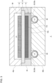
- the cathode flow path 38 is connected to the cathode electrode 12.
- the cathode flow path 38 feeds and discharges the catholyte LC to and from the cathode electrode 12.
- a groove is provided on a main surface facing the cathode electrode 12 side. This groove forms the cathode flow path 38.
- the first cathode pipe 26 and the second cathode pipe 28 are connected to the cathode flow path 38.
- the supply flow path 38a is disposed near one end of the plate member 42b in a horizontal direction, and the collection flow path 38b is disposed near the other end of the plate member 42b in the horizontal direction.
- the first cathode pipe 26 is connected to a lower end of the supply flow path 38a, and the second cathode pipe 28 is connected to an upper end of the collection flow path 38b.
- the catholyte LC flowing from the first cathode pipe 26 into the supply flow path 38a flows from the lower side to the upper side in the supply flow path 38a, and is sent to the cathode electrode 12.
- the catholyte LC flowing into the cathode electrode 12 moves toward the collection flow path 38b in the cathode electrode 12.
- the catholyte LC that has reached the collection flow path 38b flows into the collection flow path 38b from the cathode electrode 12. Then, the catholyte LC flows from the lower side to the upper side in the collection flow path 38b and is discharged to the second cathode pipe 28.
- connection positions of the first cathode pipe 26 and the second cathode pipe 28 with respect to the cathode flow path 38 can be appropriately changed.
- each pipe may be connected to a side surface rather than a bottom surface and a top surface of the cathode flow path 38.
- the number and arrangement of the supply flow path 38a and the collection flow path 38b can be appropriately changed.
- the supply flow path 38a and the collection flow path 38b are disposed so as to overlap the membrane electrode assembly 8 when viewed from the lamination direction of the cathode electrode 12, the membrane 14, and the anode electrode 10.
- a high pressure is applied to the membrane electrode assembly to bring the layers into close contact with each other. Accordingly, the production efficiency of the organic hydride can be increased.
- the pressure applied to the membrane electrode assembly is larger than the pressure applied to a general fuel cell. For this reason, when the membrane electrode assembly 8 and the cathode flow path 38 overlap each other, the membrane electrode assembly 8 can be fitted into the cathode flow path 38.
- a pressure loss generated in the catholyte LC flowing through the cathode flow path 38 may increase.
- the cathode flow path 38 is blocked, the supply of the substance to be hydrogenated to the cathode electrode 12 is delayed, and the reaction for producing the organic hydride in at least a part of the cathode electrode 12 may be stopped.
- generation of hydrogen occurs due to the side reactions, and the Faraday efficiency during production of the organic hydride may be reduced.
- the organic hydride production apparatus 2 of the present embodiment includes the support member 40 that supports the membrane electrode assembly 8 so as to suppress fitting of the membrane electrode assembly 8 into the cathode flow path 38. This makes it possible to maintain the circulation of the catholyte LC in the cathode flow path 38. Therefore, the stability of the electrolytic performance of the organic hydride production apparatus 2 can be improved.
- the collection flow path 38b is located at the downstream of the supply flow path 38a in the flow of the catholyte LC, and tends to have a lower internal pressure than the supply flow path 38a. For this reason, in the collection flow path 38b, the membrane electrode assembly 8 is easily fitted as compared with the supply flow path 38a. Therefore, the support member 40 is preferably disposed at least in the collection flow path 38b. In the present embodiment, the support members 40 are disposed in both the supply flow path 38a and the collection flow path 38b. When the driving of the cathode pump 32 is stopped and the supply of the catholyte LC to the cathode electrode 12 is stopped, the internal pressure of the supply flow path 38a may also decrease. Therefore, by disposing the support member 40 in both the supply flow path 38a and the collection flow path 38b, the stability of the electrolytic performance of the organic hydride production apparatus 2 can be further improved.
- the support member 40 as an example is an elongated body extending along the cathode flow path 38 in the cathode flow path 38. That is, the support member 40 provided in the supply flow path 38a extends along the supply flow path 38a, and the support member 40 provided in the collection flow path 38b extends along the collection flow path 38b.
- the support member 40 has a curved portion protruding toward the membrane electrode assembly 8. This makes it easy to suppress fitting of the membrane electrode assembly 8 into the cathode flow path 38.
- the support member 40 according to the present embodiment is formed of a coil.
- the coil is formed of a metal such as titanium or stainless steel, for example.
- the coil spirally extends from one end side to the other end side inside each of the supply flow path 38a and the collection flow path 38b, that is, inside the groove forming each flow path. This makes it possible to suppress fitting of the membrane electrode assembly 8 into the cathode flow path 38 while suppressing inhibition of the circulation of the catholyte LC by the support member 40.
- the support member 40 of the embodiment is formed of a coil, but is not particularly limited to this configuration.
- the support member 40 may be formed of a stent.
- the stent is a meshed tube. Therefore, the stent has a curved portion protruding toward the membrane electrode assembly 8.
- the stent also extends along the cathode flow path 38.
- the material of the stent is similar to that of the coil.
- the support member 40 may be formed of a porous member having liquid permeability such as porous ceramics.
- the porous member may have a curved portion protruding toward the membrane electrode assembly 8, or may be an elongated body extending along the cathode flow path 38.
- the support member 40 may be formed of a plate material interposed between the cathode flow path 38 and the membrane electrode assembly 8 and having a plurality of through holes.
- a plate material include a punching plate and a mesh plate.
- the plate material is laminated between the plate member 42b and the diffusion layer 12b. Also in such an aspect, fitting of the membrane electrode assembly 8 can be suppressed while the circulation of the catholyte LC between the cathode flow path 38 and the cathode electrode 12 is maintained.
- An organic hydride production apparatus (2) including:
- the organic hydride production apparatus (2) according to the first item including:
- the organic hydride production apparatus (2) according to the third item, wherein the support member (40) is disposed in both the supply flow path (38a) and the collection flow path (38b).
- the organic hydride production apparatus (2) according to any one of the first to fourth items, wherein the support member (40) is an elongated body extending along the cathode flow path (38) in the cathode flow path (38) .
- the organic hydride production apparatus (2) according to the fifth item, wherein the support member (40) has a curved portion protruding toward the membrane electrode assembly (8).
- the organic hydride production apparatus (2) according to the sixth item, wherein the support member (40) is formed of a coil or a stent.
- the organic hydride production apparatus (2) according to any one of the first to sixth items, wherein the support member (40) is formed of a porous member disposed in the cathode flow path (38).
- the organic hydride production apparatus (2) according to any one of the first to fourth items, wherein the support member (40) is formed of a plate material interposed between the cathode flow path (38) and the membrane electrode assembly (8) and having a plurality of through holes.
- An organic hydride production apparatus was prepared in which the support member formed of the coil was disposed in the cathode flow path (both the supply flow path and the collection flow path).
- a catholyte having a toluene concentration of 100% was circulated through the cathode electrode of the organic hydride production apparatus.
- an aqueous sulfuric acid solution was circulated as an anolyte to the anode electrode.
- an electrolytic reaction was performed at a current density of 0.6 A/cm 2 . The electrolytic reaction was performed until the Faraday efficiency converted from the production amount of by-product hydrogen reached 95%.
- the electrolytic reaction was performed in the similar manner, and the toluene concentration of the catholyte at the Faraday efficiency of 95% was measured. The results are shown in Fig. 5 .
- the toluene concentration corresponds to the electrolytic performance at the initial stage of use of the organic hydride production apparatus. This means that the electrolysis performance is higher when the toluene concentration is lower.
- a catholyte having a toluene concentration of 18% was supplied to the organic hydride production apparatus of Example 1, and the daily start and stop (DSS) operation was performed at a current density of 0.6 A/cm 2 for 4 weeks.
- DSS daily start and stop
- the operation for 6 hours and the stop for 18 hours were alternately repeated.
- the toluene concentration was maintained at 18% by replenishing the catholyte with toluene and discharging the catholyte.
- the electrolytic reaction was performed at the current density of 0.6 A/cm 2 , and the toluene concentration of the catholyte at the Faraday efficiency of 95% was measured. The results are shown in Fig. 5 .
- An organic hydride production apparatus having the same configuration as Example 1 except that no support member was provided was prepared. Then, the electrolytic reaction was performed under the same conditions as Example 1, and the toluene concentration of the catholyte at the Faraday efficiency of 95% at the initial stage of use of the organic hydride production apparatus was measured. The results are shown in Fig. 5 .
- the DSS operation was performed under the same conditions as Example 1 except that the period was set to three weeks. After completion of the DSS operation, the electrolytic reaction was performed at the current density of 0.6 A/cm 2 , and the toluene concentration of the catholyte at the Faraday efficiency of 95% was measured. The results are shown in Fig. 5 .
- Fig. 5 is a diagram showing a relation between a current density and a toluene concentration at Faraday efficiency (F efficiency) of 95% in the organic hydride production apparatuses of Example 1 and Comparative Example 1.
- F efficiency Faraday efficiency
- the present invention can be used in an organic hydride production apparatus.
- organic hydride production apparatus 8 membrane electrode assembly, 10 anode electrode, 12 cathode electrode, 14 membrane, 38 cathode flow path, 38a supply flow path, 38b collection flow path, 40 support member, 42b plate member
Landscapes
- Chemical & Material Sciences (AREA)
- Organic Chemistry (AREA)
- Engineering & Computer Science (AREA)
- Chemical Kinetics & Catalysis (AREA)
- Electrochemistry (AREA)
- Materials Engineering (AREA)
- Metallurgy (AREA)
- Electrolytic Production Of Non-Metals, Compounds, Apparatuses Therefor (AREA)
Applications Claiming Priority (2)
| Application Number | Priority Date | Filing Date | Title |
|---|---|---|---|
| JP2022042760 | 2022-03-17 | ||
| PCT/JP2023/004019 WO2023176197A1 (ja) | 2022-03-17 | 2023-02-07 | 有機ハイドライド製造装置 |
Publications (2)
| Publication Number | Publication Date |
|---|---|
| EP4495293A1 true EP4495293A1 (de) | 2025-01-22 |
| EP4495293A4 EP4495293A4 (de) | 2026-03-18 |
Family
ID=88022778
Family Applications (1)
| Application Number | Title | Priority Date | Filing Date |
|---|---|---|---|
| EP23770158.6A Pending EP4495293A4 (de) | 2022-03-17 | 2023-02-07 | Vorrichtung zur herstellung von organischem hydrid |
Country Status (5)
| Country | Link |
|---|---|
| US (1) | US20250198021A1 (de) |
| EP (1) | EP4495293A4 (de) |
| CN (1) | CN118984889A (de) |
| AU (1) | AU2023233972A1 (de) |
| WO (1) | WO2023176197A1 (de) |
Family Cites Families (5)
| Publication number | Priority date | Publication date | Assignee | Title |
|---|---|---|---|---|
| EP2660356A4 (de) | 2010-12-28 | 2014-07-09 | Jx Nippon Oil & Energy Corp | Vorrichtung zur hydrierung organischer verbindungen und hydrierungsverfahren |
| JP6501141B2 (ja) * | 2014-11-21 | 2019-04-17 | 国立大学法人横浜国立大学 | 有機ハイドライド製造装置およびこれを用いた有機ハイドライドの製造方法 |
| JP6786426B2 (ja) * | 2016-03-23 | 2020-11-18 | Eneos株式会社 | 電気化学還元装置及び芳香族炭化水素化合物の水素化体の製造方法 |
| KR102518546B1 (ko) * | 2018-02-09 | 2023-04-07 | 현대자동차주식회사 | 연료전지용 단위 셀 |
| JP7410724B2 (ja) * | 2020-01-07 | 2024-01-10 | Eneos株式会社 | 有機ハイドライド製造装置および有機ハイドライドの製造方法 |
-
2023
- 2023-02-07 US US18/844,585 patent/US20250198021A1/en active Pending
- 2023-02-07 EP EP23770158.6A patent/EP4495293A4/de active Pending
- 2023-02-07 AU AU2023233972A patent/AU2023233972A1/en active Pending
- 2023-02-07 CN CN202380025836.4A patent/CN118984889A/zh active Pending
- 2023-02-07 WO PCT/JP2023/004019 patent/WO2023176197A1/ja not_active Ceased
Also Published As
| Publication number | Publication date |
|---|---|
| EP4495293A4 (de) | 2026-03-18 |
| JPWO2023176197A1 (de) | 2023-09-21 |
| AU2023233972A1 (en) | 2024-09-26 |
| CN118984889A (zh) | 2024-11-19 |
| WO2023176197A1 (ja) | 2023-09-21 |
| US20250198021A1 (en) | 2025-06-19 |
Similar Documents
| Publication | Publication Date | Title |
|---|---|---|
| Merino‐Garcia et al. | Productivity and selectivity of gas‐phase CO2 electroreduction to methane at copper nanoparticle‐based electrodes | |
| CN103160851B (zh) | 膜反应器 | |
| US11519082B2 (en) | Organic hydride production apparatus and method for producing organic hydride | |
| CN103160849B (zh) | 二氧化碳电化学还原转化利用的方法 | |
| CN107075700B (zh) | 有机氢化物制造装置及使用其的有机氢化物的制造方法 | |
| WO2019136018A2 (en) | Multi-step process and system for converting carbon dioxide to multi-carbon products | |
| RU2733378C1 (ru) | Устройство для производства органического гидрида | |
| CN103160850B (zh) | 膜反应器 | |
| WO2018037774A1 (ja) | カソード、有機ハイドライド製造用電解セル及び有機ハイドライドの製造方法 | |
| CN114402095B (zh) | 错流式水电解 | |
| EP4257730A1 (de) | System zur herstellung von organischem hydrid, steuerungsvorrichtung für system zur herstellung von organischem hydrid und steuerungsverfahren für system zur herstellung von organischem hydrid | |
| CN116615577A (zh) | 水电解槽系统 | |
| EP4495293A1 (de) | Vorrichtung zur herstellung von organischem hydrid | |
| EP4296405A1 (de) | Vorrichtung zur herstellung von organischem hydrid und verfahren zur herstellung von organischem hydrid | |
| EP4495294A1 (de) | Vorrichtung zur herstellung von organischem hydrid | |
| EP4582591A1 (de) | Vorrichtung zur herstellung von organischem hydrid und verfahren zur herstellung von organischem hydrid | |
| US20260035807A1 (en) | Apparatus for producing organic hydride | |
| EP4700157A1 (de) | Vorrichtung zur herstellung von organischem hydrid und verfahren zur herstellung von organischem hydrid | |
| WO2016153341A1 (en) | Bipolar membrane electrode assembly for fuel generation | |
| Kasahara | Water electrolysis | |
| WO2025225524A1 (ja) | 有機ハイドライド製造装置、有機ハイドライド製造システム及び移行水の再利用方法 | |
| Luo et al. | Efficient and stable ethanol hybrid alkaline water electrolysis under industrial-relevant current density |
Legal Events
| Date | Code | Title | Description |
|---|---|---|---|
| STAA | Information on the status of an ep patent application or granted ep patent |
Free format text: STATUS: THE INTERNATIONAL PUBLICATION HAS BEEN MADE |
|
| PUAI | Public reference made under article 153(3) epc to a published international application that has entered the european phase |
Free format text: ORIGINAL CODE: 0009012 |
|
| STAA | Information on the status of an ep patent application or granted ep patent |
Free format text: STATUS: REQUEST FOR EXAMINATION WAS MADE |
|
| 17P | Request for examination filed |
Effective date: 20240903 |
|
| AK | Designated contracting states |
Kind code of ref document: A1 Designated state(s): AL AT BE BG CH CY CZ DE DK EE ES FI FR GB GR HR HU IE IS IT LI LT LU LV MC ME MK MT NL NO PL PT RO RS SE SI SK SM TR |
|
| DAV | Request for validation of the european patent (deleted) | ||
| DAX | Request for extension of the european patent (deleted) | ||
| REG | Reference to a national code |
Ref country code: DE Ref legal event code: R079 Free format text: PREVIOUS MAIN CLASS: C25B0009000000 Ipc: C25B0003250000 |
|
| A4 | Supplementary search report drawn up and despatched |
Effective date: 20260216 |
|
| RIC1 | Information provided on ipc code assigned before grant |
Ipc: C25B 3/25 20210101AFI20260210BHEP Ipc: C25B 3/03 20210101ALI20260210BHEP Ipc: C25B 3/05 20210101ALI20260210BHEP Ipc: C25B 3/09 20210101ALI20260210BHEP Ipc: C25B 9/23 20210101ALI20260210BHEP Ipc: C25B 9/63 20210101ALI20260210BHEP |