EP4495060A1 - Fuel treatment device - Google Patents
Fuel treatment device Download PDFInfo
- Publication number
- EP4495060A1 EP4495060A1 EP22931957.9A EP22931957A EP4495060A1 EP 4495060 A1 EP4495060 A1 EP 4495060A1 EP 22931957 A EP22931957 A EP 22931957A EP 4495060 A1 EP4495060 A1 EP 4495060A1
- Authority
- EP
- European Patent Office
- Prior art keywords
- flow path
- gas
- outer peripheral
- combustion
- processing device
- Prior art date
- Legal status (The legal status is an assumption and is not a legal conclusion. Google has not performed a legal analysis and makes no representation as to the accuracy of the status listed.)
- Granted
Links
Images




Classifications
-
- C—CHEMISTRY; METALLURGY
- C01—INORGANIC CHEMISTRY
- C01B—NON-METALLIC ELEMENTS; COMPOUNDS THEREOF; METALLOIDS OR COMPOUNDS THEREOF NOT COVERED BY SUBCLASS C01C
- C01B3/00—Hydrogen; Gaseous mixtures containing hydrogen; Separation of hydrogen from mixtures containing it; Purification of hydrogen; Reversible storage of hydrogen
- C01B3/02—Production of hydrogen; Production of gaseous mixtures containing hydrogen
- C01B3/32—Production of hydrogen; Production of gaseous mixtures containing hydrogen by reaction of gaseous or liquid organic compounds with gasifying agents, e.g. water, carbon dioxide or air
- C01B3/34—Production of hydrogen; Production of gaseous mixtures containing hydrogen by reaction of gaseous or liquid organic compounds with gasifying agents, e.g. water, carbon dioxide or air by reaction of hydrocarbons with gasifying agents
- C01B3/38—Production of hydrogen; Production of gaseous mixtures containing hydrogen by reaction of gaseous or liquid organic compounds with gasifying agents, e.g. water, carbon dioxide or air by reaction of hydrocarbons with gasifying agents using catalysts
-
- H—ELECTRICITY
- H01—ELECTRIC ELEMENTS
- H01M—PROCESSES OR MEANS, e.g. BATTERIES, FOR THE DIRECT CONVERSION OF CHEMICAL ENERGY INTO ELECTRICAL ENERGY
- H01M8/00—Fuel cells; Manufacture thereof
- H01M8/04—Auxiliary arrangements, e.g. for control of pressure or for circulation of fluids
- H01M8/04007—Auxiliary arrangements, e.g. for control of pressure or for circulation of fluids related to heat exchange
- H01M8/04014—Heat exchange using gaseous fluids; Heat exchange by combustion of reactants
- H01M8/04022—Heating by combustion
-
- B—PERFORMING OPERATIONS; TRANSPORTING
- B01—PHYSICAL OR CHEMICAL PROCESSES OR APPARATUS IN GENERAL
- B01J—CHEMICAL OR PHYSICAL PROCESSES, e.g. CATALYSIS OR COLLOID CHEMISTRY; THEIR RELEVANT APPARATUS
- B01J8/00—Chemical or physical processes in general, conducted in the presence of fluids and solid particles; Apparatus for such processes
- B01J8/02—Chemical or physical processes in general, conducted in the presence of fluids and solid particles; Apparatus for such processes with stationary particles, e.g. in fixed beds
- B01J8/0242—Chemical or physical processes in general, conducted in the presence of fluids and solid particles; Apparatus for such processes with stationary particles, e.g. in fixed beds the fluid flow within the bed being predominantly vertical
- B01J8/0257—Chemical or physical processes in general, conducted in the presence of fluids and solid particles; Apparatus for such processes with stationary particles, e.g. in fixed beds the fluid flow within the bed being predominantly vertical in a cylindrical annular shaped bed
-
- B—PERFORMING OPERATIONS; TRANSPORTING
- B01—PHYSICAL OR CHEMICAL PROCESSES OR APPARATUS IN GENERAL
- B01J—CHEMICAL OR PHYSICAL PROCESSES, e.g. CATALYSIS OR COLLOID CHEMISTRY; THEIR RELEVANT APPARATUS
- B01J8/00—Chemical or physical processes in general, conducted in the presence of fluids and solid particles; Apparatus for such processes
- B01J8/02—Chemical or physical processes in general, conducted in the presence of fluids and solid particles; Apparatus for such processes with stationary particles, e.g. in fixed beds
- B01J8/0285—Heating or cooling the reactor
-
- H—ELECTRICITY
- H01—ELECTRIC ELEMENTS
- H01M—PROCESSES OR MEANS, e.g. BATTERIES, FOR THE DIRECT CONVERSION OF CHEMICAL ENERGY INTO ELECTRICAL ENERGY
- H01M8/00—Fuel cells; Manufacture thereof
- H01M8/04—Auxiliary arrangements, e.g. for control of pressure or for circulation of fluids
- H01M8/04298—Processes for controlling fuel cells or fuel cell systems
- H01M8/04694—Processes for controlling fuel cells or fuel cell systems characterised by variables to be controlled
- H01M8/04746—Pressure; Flow
-
- H—ELECTRICITY
- H01—ELECTRIC ELEMENTS
- H01M—PROCESSES OR MEANS, e.g. BATTERIES, FOR THE DIRECT CONVERSION OF CHEMICAL ENERGY INTO ELECTRICAL ENERGY
- H01M8/00—Fuel cells; Manufacture thereof
- H01M8/06—Combination of fuel cells with means for production of reactants or for treatment of residues
- H01M8/0606—Combination of fuel cells with means for production of reactants or for treatment of residues with means for production of gaseous reactants
-
- H—ELECTRICITY
- H01—ELECTRIC ELEMENTS
- H01M—PROCESSES OR MEANS, e.g. BATTERIES, FOR THE DIRECT CONVERSION OF CHEMICAL ENERGY INTO ELECTRICAL ENERGY
- H01M8/00—Fuel cells; Manufacture thereof
- H01M8/06—Combination of fuel cells with means for production of reactants or for treatment of residues
- H01M8/0606—Combination of fuel cells with means for production of reactants or for treatment of residues with means for production of gaseous reactants
- H01M8/0612—Combination of fuel cells with means for production of reactants or for treatment of residues with means for production of gaseous reactants from carbon-containing material
-
- B—PERFORMING OPERATIONS; TRANSPORTING
- B01—PHYSICAL OR CHEMICAL PROCESSES OR APPARATUS IN GENERAL
- B01J—CHEMICAL OR PHYSICAL PROCESSES, e.g. CATALYSIS OR COLLOID CHEMISTRY; THEIR RELEVANT APPARATUS
- B01J2208/00—Processes carried out in the presence of solid particles; Reactors therefor
- B01J2208/00008—Controlling the process
- B01J2208/00017—Controlling the temperature
- B01J2208/00026—Controlling or regulating the heat exchange system
- B01J2208/00035—Controlling or regulating the heat exchange system involving measured parameters
- B01J2208/00044—Temperature measurement
- B01J2208/00061—Temperature measurement of the reactants
-
- B—PERFORMING OPERATIONS; TRANSPORTING
- B01—PHYSICAL OR CHEMICAL PROCESSES OR APPARATUS IN GENERAL
- B01J—CHEMICAL OR PHYSICAL PROCESSES, e.g. CATALYSIS OR COLLOID CHEMISTRY; THEIR RELEVANT APPARATUS
- B01J2208/00—Processes carried out in the presence of solid particles; Reactors therefor
- B01J2208/00008—Controlling the process
- B01J2208/00017—Controlling the temperature
- B01J2208/00106—Controlling the temperature by indirect heat exchange
- B01J2208/00168—Controlling the temperature by indirect heat exchange with heat exchange elements outside the bed of solid particles
- B01J2208/00212—Plates; Jackets; Cylinders
-
- B—PERFORMING OPERATIONS; TRANSPORTING
- B01—PHYSICAL OR CHEMICAL PROCESSES OR APPARATUS IN GENERAL
- B01J—CHEMICAL OR PHYSICAL PROCESSES, e.g. CATALYSIS OR COLLOID CHEMISTRY; THEIR RELEVANT APPARATUS
- B01J2208/00—Processes carried out in the presence of solid particles; Reactors therefor
- B01J2208/00008—Controlling the process
- B01J2208/00017—Controlling the temperature
- B01J2208/00504—Controlling the temperature by means of a burner
-
- B—PERFORMING OPERATIONS; TRANSPORTING
- B01—PHYSICAL OR CHEMICAL PROCESSES OR APPARATUS IN GENERAL
- B01J—CHEMICAL OR PHYSICAL PROCESSES, e.g. CATALYSIS OR COLLOID CHEMISTRY; THEIR RELEVANT APPARATUS
- B01J2208/00—Processes carried out in the presence of solid particles; Reactors therefor
- B01J2208/00008—Controlling the process
- B01J2208/00017—Controlling the temperature
- B01J2208/0053—Controlling multiple zones along the direction of flow, e.g. pre-heating and after-cooling
-
- B—PERFORMING OPERATIONS; TRANSPORTING
- B01—PHYSICAL OR CHEMICAL PROCESSES OR APPARATUS IN GENERAL
- B01J—CHEMICAL OR PHYSICAL PROCESSES, e.g. CATALYSIS OR COLLOID CHEMISTRY; THEIR RELEVANT APPARATUS
- B01J2208/00—Processes carried out in the presence of solid particles; Reactors therefor
- B01J2208/00008—Controlling the process
- B01J2208/00548—Flow
-
- C—CHEMISTRY; METALLURGY
- C01—INORGANIC CHEMISTRY
- C01B—NON-METALLIC ELEMENTS; COMPOUNDS THEREOF; METALLOIDS OR COMPOUNDS THEREOF NOT COVERED BY SUBCLASS C01C
- C01B2203/00—Integrated processes for the production of hydrogen or synthesis gas
- C01B2203/02—Processes for making hydrogen or synthesis gas
- C01B2203/0205—Processes for making hydrogen or synthesis gas containing a reforming step
- C01B2203/0227—Processes for making hydrogen or synthesis gas containing a reforming step containing a catalytic reforming step
- C01B2203/0233—Processes for making hydrogen or synthesis gas containing a reforming step containing a catalytic reforming step the reforming step being a steam reforming step
-
- C—CHEMISTRY; METALLURGY
- C01—INORGANIC CHEMISTRY
- C01B—NON-METALLIC ELEMENTS; COMPOUNDS THEREOF; METALLOIDS OR COMPOUNDS THEREOF NOT COVERED BY SUBCLASS C01C
- C01B2203/00—Integrated processes for the production of hydrogen or synthesis gas
- C01B2203/08—Methods of heating or cooling
- C01B2203/0805—Methods of heating the process for making hydrogen or synthesis gas
- C01B2203/0811—Methods of heating the process for making hydrogen or synthesis gas by combustion of fuel
-
- C—CHEMISTRY; METALLURGY
- C01—INORGANIC CHEMISTRY
- C01B—NON-METALLIC ELEMENTS; COMPOUNDS THEREOF; METALLOIDS OR COMPOUNDS THEREOF NOT COVERED BY SUBCLASS C01C
- C01B2203/00—Integrated processes for the production of hydrogen or synthesis gas
- C01B2203/16—Controlling the process
- C01B2203/1695—Adjusting the feed of the combustion
-
- H—ELECTRICITY
- H01—ELECTRIC ELEMENTS
- H01M—PROCESSES OR MEANS, e.g. BATTERIES, FOR THE DIRECT CONVERSION OF CHEMICAL ENERGY INTO ELECTRICAL ENERGY
- H01M8/00—Fuel cells; Manufacture thereof
- H01M8/10—Fuel cells with solid electrolytes
- H01M8/12—Fuel cells with solid electrolytes operating at high temperature, e.g. with stabilised ZrO2 electrolyte
-
- Y—GENERAL TAGGING OF NEW TECHNOLOGICAL DEVELOPMENTS; GENERAL TAGGING OF CROSS-SECTIONAL TECHNOLOGIES SPANNING OVER SEVERAL SECTIONS OF THE IPC; TECHNICAL SUBJECTS COVERED BY FORMER USPC CROSS-REFERENCE ART COLLECTIONS [XRACs] AND DIGESTS
- Y02—TECHNOLOGIES OR APPLICATIONS FOR MITIGATION OR ADAPTATION AGAINST CLIMATE CHANGE
- Y02E—REDUCTION OF GREENHOUSE GAS [GHG] EMISSIONS, RELATED TO ENERGY GENERATION, TRANSMISSION OR DISTRIBUTION
- Y02E60/00—Enabling technologies; Technologies with a potential or indirect contribution to GHG emissions mitigation
- Y02E60/30—Hydrogen technology
- Y02E60/50—Fuel cells
Definitions
- This invention relates to a fuel processing device.
- a fuel processing device is used in a fuel cell system, a hydrogen station, or the like.
- the fuel processing device generates a reformed gas containing hydrogen by a reforming reaction of a hydrocarbon-based raw material such as a natural gas, alcohols, or ammonia.
- the reforming reaction is an endothermic reaction, and hence thermal energy is required for the reforming reaction.
- the fuel processing device includes a combustor configured to generate thermal energy.
- a hydrogen generating device in Patent Literature 1, includes a reformer, a combustor, and an exhaust gas path.
- a reforming catalyst is filled inside the reformer.
- the reformer reforms a fuel to generate a reformed gas containing hydrogen.
- the combustor heats the reformer.
- the exhaust gas path covers a periphery of an outer wall of the reformer.
- a combustion exhaust gas from the combustor flows through the exhaust gas path.
- the reformer is mainly heated from an outer peripheral side by the combustion exhaust gas, and hence there is a limitation in the heat transfer area between the reformer and the combustion exhaust gas.
- thermal efficiency is degraded.
- This invention has been made in order to solve the problems as described above, and has an object to provide a fuel processing device that can obtain a higher thermal efficiency.
- a fuel processing device including: a reforming unit configured to generate a reformed gas from a raw material; and a combustion unit configured to combust a fuel and a combustion supporting gas in a combustion space to generate a combustion gas.
- the reforming unit includes: a first tubular wall; and a second tubular wall arranged on an outer peripheral side with respect to the first tubular wall.
- a reforming reaction flow path is formed between the first tubular wall and the second tubular wall, the reforming reaction flow path being configured to be filled with a reforming catalyst and to allow the raw material and the reformed gas to flow through the reforming reaction flow path.
- a combustion gas flow path configured to allow the combustion gas to flow through the combustion gas flow path is formed on an inner peripheral side with respect to the first tubular wall. The combustion gas flow path is adjacent to the reforming reaction flow path across the first tubular wall.
- An outer peripheral flow path configured to allow an outer peripheral gas to flow through the outer peripheral flow path is formed on an outer peripheral side with respect to the second tubular wall.
- the outer peripheral flow path is adjacent to the reforming reaction flow path across the second tubular wall.
- the fuel processing device further includes: a merging portion configured to allow the combustion gas having flowed through the combustion gas flow path and the outer peripheral gas having flowed through the outer peripheral flow path to merge with each other; an exhaust gas flow path configured to allow the combustion gas and the outer peripheral gas that have merged at the merging portion to flow through the exhaust gas flow path as an exhaust gas; an oxidizing agent flow path configured to allow an oxidizing agent supplied from a heating source to pass through the oxidizing agent flow path; an oxidizing agent branching portion provided in the oxidizing agent flow path; a combustion supporting gas flow path that connects between the oxidizing agent branching portion and the combustion unit and is configured to allow a part of the oxidizing agent to flow through the combustion supporting gas flow path as the combustion supporting gas; and an outer peripheral gas introducing flow path that connects between the oxidizing agent branching portion and the outer peripheral flow path and is configured to allow the other part of the oxidizing agent to flow through the outer peripheral gas introducing flow path as the outer peripheral gas.
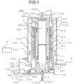
- FIG. 1 is a schematic cross-sectional view of the fuel processing device according to this embodiment.
- the up-and-down direction of FIG. 1 represents a vertical direction.
- a fuel processing device 100 has a cylindrical shape about a center axis 100a.
- the center axis 100a extends in the up-and-down direction.
- the fuel processing device 100 includes a reforming unit 110 and a combustion unit 120.
- the combustion unit 120 is provided below the reforming unit 110.
- the combustion unit 120 generates a combustion gas F51 for heating the reforming unit 110.
- the middle wall 502 is arranged on the outer peripheral side with respect to the inner wall 501 so as to surround the inner wall 501.
- the outer wall 504 is arranged on the outer peripheral side with respect to the middle wall 502 so as to surround the middle wall 502.
- the inner wall 501 is an example of a first tubular wall.
- the middle wall 502 is an example of a second tubular wall.
- a combustion gas flow path 401 is formed in a space between the flame tube wall 503 and the inner wall 501.
- the combustion gas flow path 401 is formed in an annular shape in horizontal cross section.
- the combustion gas flow path 401 extends in the up-and-down direction.
- the combustion gas F51 flows upward through the combustion gas flow path 401.
- the closing wall 505 is provided between the inner wall 501 and the middle wall 502.
- a reforming catalyst 5 is filled in the reforming reaction flow path 402.
- a catalyst layer is formed in the reforming reaction flow path 402 by the reforming catalyst 5.
- An upper end portion of the reforming catalyst 5 serves as an inlet portion of the reforming reaction flow path 402.
- a lower end portion of the reforming catalyst 5 serves as an outlet of the reforming reaction flow path 402.
- the raw material F52 is supplied to the reforming reaction flow path 402 from the outside of the fuel processing device 100.
- the reformed gas F53 is generated from the raw material F52 due to a catalytic action of the reforming catalyst 5.
- a first raw material preheating unit 203 and a second raw material preheating unit 203a are provided on the upstream side with respect to the inlet of the reforming reaction flow path 402 in the flow of the raw material F52.
- the second raw material preheating unit 203a is provided on the downstream side with respect to the first raw material preheating unit 203 in the flow of the raw material F52.
- the second raw material preheating unit 203a is formed in the space between the inner wall 501 and the middle wall 502.
- the first raw material preheating unit 203 is formed of a pipe.
- the first raw material preheating unit 203 passes through an upper surface wall 506 and the closing wall 505, and is connected to the second raw material preheating unit 203a.
- the raw material F52 passes through the first raw material preheating unit 203 and the second raw material preheating unit 203a in this order to flow into the reforming reaction flow path 402.
- the reformed gas F53 generated in the reforming reaction flow path 402 flows out to the outside of the fuel processing device 100.
- a reformed gas temperature sensor 9 is provided at the outlet of the reforming reaction flow path 402.
- the reformed gas temperature sensor 9 detects a temperature of the reformed gas F53 flowing out from the reforming reaction flow path 402, and outputs a detection signal to a controller 8.
- a catalyst layer outer peripheral flow path 403 is formed in a space between the middle wall 502 and the outer wall 504.
- the catalyst layer outer peripheral flow path 403 is formed in an annular shape in horizontal cross section.
- the catalyst layer outer peripheral flow path 403 extends in the up-and-down direction.
- the catalyst layer outer peripheral flow path 403 is adjacent to the reforming reaction flow path 402 across the middle wall 502.
- a catalyst layer outer peripheral gas F54 flows upward through the catalyst layer outer peripheral flow path 403.
- the upper surface wall 506 is formed in a disk shape about the center axis 100a.
- the upper surface wall 506 faces the closing wall 505 with a gap.
- the gap between the upper surface wall 506 and the closing wall 505 serves as a communication portion 510.
- the space between the flame tube wall 503 and the inner wall 501 and the space between the middle wall 502 and the outer wall 504 are in communication with each other through the communication portion 510.
- the first raw material preheating unit 203 passes through the communication portion 510.
- An exhaust gas flow path 404 is connected to the upper surface wall 506.
- the exhaust gas flow path 404 is provided on the center axis 100a of the fuel processing device 100.
- An exhaust gas F58 flows through the exhaust gas flow path 404.
- the flows of the raw material F52 and the reformed gas F53 in the reforming reaction flow path 402 are opposite to the flow of the combustion gas F51 in the combustion gas flow path 401 and the flow of the catalyst layer outer peripheral gas F54 in the catalyst layer outer peripheral flow path 403.
- the second raw material preheating unit 203a is sandwiched by the combustion gas flow path 401 and the catalyst layer outer peripheral flow path 403 from both sides. Heat exchange is performed through the inner wall 501 between the combustion gas F51 in the combustion gas flow path 401 and the raw material F52 in the second raw material preheating unit 203a. Heat exchange is performed through the middle wall 502 between the catalyst layer outer peripheral gas F54 in the catalyst layer outer peripheral flow path 403 and the raw material F52 in the second raw material preheating unit 203a.
- the catalyst layer outer peripheral gas F54 flows through the communication portion 510 around the first raw material preheating unit 203.
- heat exchange is performed between the catalyst layer outer peripheral gas F54 and the raw material F52.
- the first raw material preheating unit 203 may meander along the circumferential direction of the fuel processing device 100 so as to secure a larger heat transfer area between the first raw material preheating unit 203 and the catalyst layer outer peripheral gas F54.
- An upper end portion of the internal space of the flame tube wall 503 is closed by a closing wall 507.
- the closing wall 507 faces the upper surface wall 506 with a gap.
- the combustion unit 120 includes a combustor 1.
- the combustor 1 is arranged on the center axis 100a.
- the combustor 1 is arranged below the flame tube wall 503.
- a combustion fuel F55, a combustion raw material F59, and a combustion supporting gas F56 are supplied to the combustor 1.
- the combustor 1 combusts the combustion fuel F55 or the combustion raw material F59 and the combustion supporting gas F56. With this, flame is formed in a combustion space 202, and the combustion gas F51 is generated.
- a flame partition plate 3 is provided inside the flame tube wall 503.
- the internal space of the flame tube wall 503 is partitioned into an upper part and a lower part by the flame partition plate 3.
- a heat shield material 6 is provided in a space above the flame partition plate 3 and below the closing wall 507 inside the flame tube wall 503.
- a space below the flame partition plate 3 inside the flame tube wall 503 serves as a radiation heat transfer space 201.
- a lower end of the flame tube wall 503 is opened.
- the flame partition plate 3 faces the combustor 1 across the radiation heat transfer space 201.
- the radiation heat transfer space 201 is surrounded by the flame tube wall 503, the flame partition plate 3, and the combustor 1.
- the combustion space 202 is formed at a lower portion of the radiation heat transfer space 201.
- the radiation heat transfer space 201 is connected to a lower end portion of the combustion gas flow path 401.
- the combustion gas F51 generated by the combustor 1 passes through the combustion space 202 and the radiation heat transfer space 201 to flow into the combustion gas flow path 401.
- the flame partition plate 3 is heated by radiation heat from the combustion space 202 through the radiation heat transfer space 201.
- the periphery of the combustion space 202 is surrounded by a heat shield wall 4.
- the heat shield wall 4 has a cylindrical shape about the center axis of the fuel processing device 100.
- the height of the heat shield wall 4 is approximately the same as the height of the combustion space 202, that is, the height of flame formed by the combustor 1.
- An air flow path 405 is formed on the outer peripheral side of the heat shield wall 4.
- the air flow path 405 is formed in an annular shape so as to surround the periphery of the heat shield wall 4.
- Air F57 for temperature adjustment flows through the air flow path 405.
- a flow rate adjustment valve 406 configured to adjust the flow rate of the air F57 is provided.
- the flow rate adjustment valve 406 is an example of a configuration for adjusting the flow rate of the air F57.
- the air F57 is supplied from the air flow path 405 to the combustion gas F51 on the downstream side with respect to the combustion space 202 and on the upstream side with respect to the combustion gas flow path 401. With this, the temperature of the combustion gas F51 flowing into the combustion gas flow path 401 is adjusted.
- An oxidizing agent F50 is supplied to the fuel processing device 100 from a heating source (not shown).
- the oxidizing agent F50 in a state of being heated by the heating source is supplied to the fuel processing device 100.
- the oxidizing agent F50 to be supplied to the fuel processing device 100 has a temperature higher than the temperature of the raw material F52 to be supplied to the fuel processing device 100.
- the heating source in this embodiment is a high-temperature fuel cell. Further, the oxidizing agent F50 in this embodiment is a cathode off-gas supplied from the high-temperature fuel cell.
- An oxidizing agent inflow pipe 300 is provided in the fuel processing device 100.
- An oxidizing agent flow path 600 is formed inside the oxidizing agent inflow pipe 300.
- the oxidizing agent F50 flows through the oxidizing agent flow path 600.
- the oxidizing agent inflow pipe 300 branches into a combustion supporting gas conduit 302 and a catalyst layer outer peripheral gas introducing pipe 301 at an oxidizing agent branching portion 2.
- a combustion supporting gas flow path 602 is formed inside the combustion supporting gas conduit 302.
- the combustion supporting gas F56 flows through the combustion supporting gas flow path 602.
- the combustion supporting gas F56 is a part of the oxidizing agent F50.
- a catalyst layer outer peripheral gas introducing flow path 601 is formed inside the catalyst layer outer peripheral gas introducing pipe 301.
- the catalyst layer outer peripheral gas F54 flows through the catalyst layer outer peripheral gas introducing flow path 601.
- the catalyst layer outer peripheral gas F54 is the other part of the oxidizing agent F50. That is, the oxidizing agent F50 flowing through the oxidizing agent flow path 600 splits into the combustion supporting gas F56 and the catalyst layer outer peripheral gas F54 at the oxidizing agent branching portion 2.
- the ratio between the flow rate of the catalyst layer outer peripheral gas F54 and the flow rate of the combustion supporting gas F56 in the oxidizing agent branching portion 2 is set in advance in accordance with the operating condition of the fuel processing device 100 and the combustion condition of the combustor 1.
- the ratio between the flow rate of the catalyst layer outer peripheral gas F54 and the flow rate of the combustion supporting gas F56 is set to from about 3:1 to about 11: 1.
- the combustion supporting gas conduit 302 is connected to the combustor 1. With this, a part of the oxidizing agent F50 is supplied to the combustor 1 as the combustion supporting gas F56.
- the catalyst layer outer peripheral gas introducing pipe 301 is connected to a lower portion of the catalyst layer outer peripheral flow path 403. With this, the other part of the oxidizing agent F50 is supplied to the catalyst layer outer peripheral flow path 403 as the catalyst layer outer peripheral gas F54.
- the merging portion 200 is formed in a ring shape about the center axis 100a.
- the merging portion 200 in this embodiment is located at the upper end portion of the space between the flame tube wall 503 and the inner wall 501.
- the combustion gas F51 and the catalyst layer outer peripheral gas F54 that have merged at the merging portion 200 turn into the exhaust gas F58.
- the exhaust gas F58 passes through the exhaust gas flow path 404 to flow out to the outside of the fuel processing device 100.
- the fuel processing device 100 is surrounded by an appropriate heat insulating material. With this, heat loss due to heat radiation from the fuel processing device 100 is suppressed.
- the controller 8 is configured to control the entire fuel processing device 100.
- the controller 8 includes a microcomputer including, for example, a central processing unit (CPU), a read only memory (ROM), and a random access memory (RAM).
- CPU central processing unit
- ROM read only memory
- RAM random access memory
- the raw material F52 supplied to the fuel processing device 100 is preheated by the catalyst layer outer peripheral gas F54 in the first raw material preheating unit 203.
- the raw material F52 is further preheated by the combustion gas F51 and the catalyst layer outer peripheral gas F54 in the second raw material preheating unit 203a.
- the raw material F52 is preheated in the first raw material preheating unit 203 and the second raw material preheating unit 203a to be heated to from about 350 °C to about 400 °C.
- the heated raw material F52 flows into the reforming reaction flow path 402.
- the raw material F52 of the reforming reaction flow path 402 is heated from the inner peripheral side by the combustion gas F51 flowing through the combustion gas flow path 401. Further, the raw material F52 of the reforming reaction flow path 402 is heated also from the outer peripheral side by the catalyst layer outer peripheral gas F54 flowing through the catalyst layer outer peripheral flow path 403. With this, the raw material F52 passing through the reforming catalyst 5 is heated to from about 550 °C to about 650 °C. Further, the raw material F52 passing through the reforming catalyst 5 is reformed to the reformed gas F53 by a reforming reaction which is an endothermic reaction.
- a general reforming reaction is expressed by the following Formula (1) and Formula (2).
- the reforming reaction flow path 402 an endothermic reaction of methane and water vapor occurs due to the catalytic action of the reforming catalyst 5. With this reaction, hydrogen is generated. CH 4 +H 2 O ⁇ CO+3H 2 (1) CO+H 2 O ⁇ CO 2 +H 2 (2)
- the flow rate of methane and water vapor is generally represented by the S/C ratio.
- the S/C ratio is a molar fraction of water vapor (S) with respect to carbon (C) contained in the raw material.
- the flow rate of the water vapor to be supplied to the reforming reaction flow path 402 is set such that the S/C ratio becomes a constant value within a range of from about 2.5 to about 3.5.
- the reforming catalyst 5 for example, Ni-based, Pt-based, or Ru-based reforming catalyst is used.
- the reforming catalyst 5 is carried on a carrier, such as Al 2 O 3 or MgO.
- the reformed gas F53 is supplied to the high-temperature fuel cell or the like while maintaining the temperature after the reforming reaction.
- the high-temperature fuel cell include a solid oxide fuel cell and a molten carbonate fuel cell.
- the combustion gas F51 having a temperature of from about 700 °C to about 1,200 °C is generated.
- an ignition plug (not shown) is used for ignition at the combustor 1.
- the combustion gas F51 passes through the combustion space 202 and the radiation heat transfer space 201 to flow into the combustion gas flow path 401.
- the combustion gas F51 flows upward through the combustion gas flow path 401.
- the heat of the combustion gas F51 is transfer to the reforming reaction flow path 402 through the inner wall 501. With this, the temperature of the combustion gas F51 decreases to about 400 °C.
- the heat transferred to the reforming reaction flow path 402 is a part of the thermal energy required for the reforming reaction.
- Heat transfer from the combustion gas flow path 401 to the reforming reaction flow path 402 is performed by convection of the combustion gas F51. Further, the heat transfer from the combustion gas flow path 401 to the reforming reaction flow path 402 is performed also by radiation from the flame tube wall 503 and radiation from the combustion gas F51.
- the radiation heat transfer space 201 is formed at the periphery of the combustor 1, and hence a particularly large amount of heat is given to the reforming reaction flow path 402 due to radiation from the radiation heat transfer space 201.
- the downstream portion of the combustion space 202 in the flow of the combustion gas F51 is connected to the air flow path 405. With this, the air F57 for temperature adjustment is mixed with the combustion gas F51 on the downstream side with respect to the position at which combustion is completed in the combustion space 202. Thus, the temperature of the combustion gas F51 can be adjusted without affecting the combustion reaction.
- the controller 8 controls the flow rate of the air F57 based on the temperature detected by the reformed gas temperature sensor 9. For example, the controller 8 controls the flow rate adjustment valve 406 such that the flow rate of the air F57 increases as the temperature of the reformed gas F53 increases. With this, the reaction temperature of the reforming reaction expressed by the Formula (1) and the Formula (2) can be adjusted.
- the oxidizing agent F50 having a temperature of from 650 °C to 700 °C is supplied to the oxidizing agent flow path 600 from the heating source.
- the oxidizing agent F50 splits into the combustion supporting gas flow path 602 and the catalyst layer outer peripheral gas introducing flow path 601 at the oxidizing agent branching portion 2.
- a part of the oxidizing agent F50 flows through the combustion supporting gas flow path 602 as the combustion supporting gas F56.
- the combustion supporting gas F56 flows through the combustion supporting gas flow path 602 to be supplied to the combustor 1.
- the other part of the oxidizing agent F50 flows through the catalyst layer outer peripheral gas introducing flow path 601 as the catalyst layer outer peripheral gas F54.
- the catalyst layer outer peripheral gas F54 flows through the catalyst layer outer peripheral gas introducing flow path 601 to be supplied to the catalyst layer outer peripheral flow path 403.
- the catalyst layer outer peripheral gas F54 gives heat to the reforming reaction flow path 402 via the middle wall 502 while flowing through the catalyst layer outer peripheral flow path 403. The heat is the remaining thermal energy of the thermal energy required for the reforming reaction.
- the heat is given to the reforming reaction flow path 402 so that the temperature of the catalyst layer outer peripheral gas F54 decreases to about 400 °C.
- the catalyst layer outer peripheral gas F54 passes through the communication portion 510 to merge with the combustion gas F51 at the merging portion 200.
- the merged gas flows out to the outside from the exhaust gas flow path 404 as the exhaust gas F58.
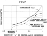
- FIG. 2 is a diagram for illustrating a temperature distribution of the fuel processing device according to this embodiment.
- the horizontal axis of FIG. 2 represents the position "x" in the center axis 100a direction.
- the position x is non-dimensional with the inlet of the reforming reaction flow path 402 being set as 0, the outlet of the reforming reaction flow path 402 being set as 1, and the length of the reforming reaction flow path 402 in the center axis 100a direction being set as L.
- the range in which the position "x" is a negative value indicates the second raw material preheating unit 203a or the first raw material preheating unit 203.
- the merging portion 200 in this embodiment is provided at a position smaller than 0 in the center axis 100a direction.
- the vertical axis of FIG. 2 represents the temperature (°C).
- the solid line in FIG. 2 represents the temperature of the combustion gas F51.
- the long-dashed broken line in FIG. 2 represents the temperature of the catalyst layer outer peripheral gas F54.
- the short-dashed broken line in FIG. 2 represents the temperature of the raw material F52 and the reformed gas F53.
- the reforming reaction expressed by the Formula (1) and the Formula (2) is affected by the temperature distribution of the raw material F52 and the reformed gas F53 flowing through the reforming reaction flow path 402.
- the combustion supporting gas F56 is supplied to the combustor 1.
- the combustion supporting gas F56 is a part of the oxidizing agent F50 that has split at the oxidizing agent branching portion 2.
- the flow rate of the combustion supporting gas F56 defines the flame temperature at the time of combustion and affects the combustion state. That is, when it is assumed that the flow rate of the combustion fuel F55 is constant, the heat insulating flame temperature is theoretically determined.
- the flame temperature When the flame temperature is excessively high, there is a fear in that the heat resistance of the member forming the fuel processing device 100 cannot be secured. In contrast, when the flame temperature is excessively low, heat transfer from the combustion gas F51 to the raw material F52 and the reformed gas F53 is difficult. That is, there is an appropriate range for the flame temperature. Further, there is a range of an appropriate oxygen ratio for completely combusting the combustion fuel F55 in the combustion space 202. Thus, the flow rate of the combustion supporting gas F56, that is, a distribution ratio at the oxidizing agent branching portion 2 is substantially determined.
- each of the flame temperature and the oxygen ratio falls within an appropriate range in accordance with the flow rate of the combustion fuel F55, and, when the thermal energy of the catalyst layer outer peripheral gas F54 and the combustion supporting gas F56 falls within an appropriate range, the temperature of the combustion gas F51 and the temperature of the catalyst layer outer peripheral gas F54 decrease similarly from the right side to the left side of FIG. 2 .
- the temperature of the combustion gas F51 and the temperature of the catalyst layer outer peripheral gas F54 are approximately the same.
- the oxidizing agent F50 is not limited to the cathode off-gas supplied from the high-temperature fuel cell. It is only required that the oxidizing agent F50 have a gas temperature of about 600 °C or more and contain a required amount of a composition that is a combustion-supporting gas of a combustion reaction. As the oxidizing agent F50, a high-temperature oxygen-containing exhaust gas in a plant, or the like, can be used.
- Fuel to be supplied to the combustor 1 may be the same as the raw material F52 or may be different from the raw material F52.
- a material which is the same as the raw material F52 and a material different from the raw material F52 may be mixed with each other.
- the combustion fuel F55 may be a part or an entirety of an anode off-gas. From about 70 % to about 90 % of the hydrogen contained in the reformed gas F53 is consumed for power generation in a fuel cell stack. The remaining hydrogen is contained in the anode off-gas. Thus, a part or an entirety of the anode off-gas can be supplied to the combustor 1 as the combustion fuel F55.
- the combustion raw material F59 is the same as the raw material F52.
- the combustion raw material F59 is supplied to the combustor 1, for example, in a temperature rise process at the time of activation of the fuel processing device 100.
- a material in which a part or an entirety of the anode off-gas and the raw material F52 are mixed with each other may be used.
- a part of the oxidizing agent F50 supplied from the heating source is used as the combustion supporting gas F56, and the other part of the oxidizing agent F50 is used as the catalyst layer outer peripheral gas F54.
- the combustion supporting gas F56 is supplied to the combustor 1 to be combusted together with the combustion fuel F55 or the combustion raw material F59.
- the catalyst layer outer peripheral gas F54 passes through the catalyst layer outer peripheral flow path 403 to give heat to the second raw material preheating unit 203a and the reforming reaction flow path 402 from the outer peripheral side.
- the combustion gas F51 generated by combustion passes through the combustion gas flow path 401 to give heat to the second raw material preheating unit 203a and the reforming reaction flow path 402 from the inner peripheral side.
- heat is given to the second raw material preheating unit 203a and the reforming reaction flow path 402 from both sides of the outer peripheral side and the inner peripheral side.
- the heat transfer area with respect to the second raw material preheating unit 203a and the reforming reaction flow path 402 can be increased, thereby being capable of decreasing the loss of the thermal energy.
- the fuel processing device with a high thermal efficiency is achieved. Further, the heat transfer property is improved, thereby being capable of attaining a reduction in size of the fuel processing device 100.
- a temperature difference may be caused in the combustion gas F51 in the circumferential direction due to the combustion state of the combustor 1.
- a temperature difference may be caused also in the flame tube wall 503 in the circumferential direction.
- the radiation heat transfer space 201 is provided on the inner side of the flame tube wall 503.
- the flame partition plate 3 and the heat shield material 6 are provided on the inner peripheral side of the downstream-side portion of the combustion gas flow path 401.
- the flame partition plate 3 and the heat shield material 6 are provided on the inner peripheral side of the downstream-side portion of the combustion gas flow path 401.
- the fuel processing device 100 includes the reforming unit 110 and the combustion unit 120.
- the reforming unit 110 is configured to generate the reformed gas F53 from the raw material F52.
- the combustion unit 120 is configured to combust the combustion fuel F55 or the combustion raw material F59 and the combustion supporting gas F56 in the combustion space 202 to generate the combustion gas F51.
- the reforming unit 110 includes the inner wall 501, and the middle wall 502 arranged on the outer peripheral side with respect to the inner wall 501.
- the reforming reaction flow path 402 is formed between the inner wall 501 and the middle wall 502.
- the reforming catalyst 5 is filled in the reforming reaction flow path 402.
- the raw material F52 and the reformed gas F53 flow through the reforming reaction flow path 402.
- the combustion gas flow path 401 is formed on the inner peripheral side with respect to the inner wall 501.
- the combustion gas F51 flows through the combustion gas flow path 401.
- the combustion gas flow path 401 is adjacent to the reforming reaction flow path 402 across the inner wall 501.
- the catalyst layer outer peripheral flow path 403 is formed on the outer peripheral side with respect to the middle wall 502.
- the catalyst layer outer peripheral gas F54 flows through the catalyst layer outer peripheral flow path 403.
- the catalyst layer outer peripheral flow path 403 is adjacent to the reforming reaction flow path 402 across the middle wall 502.
- the fuel processing device 100 further includes the merging portion 200, the exhaust gas flow path 404, the oxidizing agent flow path 600, the oxidizing agent branching portion 2, the combustion supporting gas flow path 602, and the catalyst layer outer peripheral gas introducing flow path 601.
- the combustion gas F51 and the catalyst layer outer peripheral gas F54 that have merged at the merging portion 200 flow through the exhaust gas flow path 404 as the exhaust gas F58.
- the oxidizing agent F50 supplied from the heating source flows through the oxidizing agent flow path 600.
- the oxidizing agent branching portion 2 is provided in the oxidizing agent flow path 600.
- the combustion supporting gas flow path 602 connects between the oxidizing agent branching portion 2 and the combustion unit 120.
- the combustion supporting gas flow path 602 allows a part of the oxidizing agent F50 to flow therethrough as the combustion supporting gas F56.
- the catalyst layer outer peripheral gas introducing flow path 601 connects between the oxidizing agent branching portion 2 and the catalyst layer outer peripheral flow path 403.
- the catalyst layer outer peripheral gas introducing flow path 601 allows the other part of the oxidizing agent F50 to flow therethrough.
- combustion fuel F55 and the combustion raw material F59 are examples of fuel.
- the inner wall 501 is an example of the first tubular wall.
- the middle wall 502 is an example of the second tubular wall.
- the catalyst layer outer peripheral flow path 403 is an example of an outer peripheral flow path.
- the catalyst layer outer peripheral gas F54 is an example of an outer peripheral gas.
- the catalyst layer outer peripheral gas introducing flow path 601 is an example of an outer peripheral gas introducing flow path.
- the raw material F52 and the reformed gas F53 in the reforming reaction flow path 402 are heated by the combustion gas F51 in the combustion gas flow path 401 from the inner peripheral side, and is heated from the outer peripheral side by the catalyst layer outer peripheral gas F54 in the catalyst layer outer peripheral flow path 403.
- the heat transfer area with respect to the reforming reaction flow path 402 can be increased, thereby being capable of obtaining a higher thermal efficiency in the fuel processing device 100.
- the temperature distribution of the reforming reaction flow path 402 can be made uniform in the radial direction, thereby being capable of obtaining the reformed gas F53 with a small composition variation due to a reaction.
- heat radiation from the reforming reaction flow path 402 can be suppressed, thereby being capable of reducing the loss of the thermal energy.
- the fuel processing device 100 further includes the flame tube wall 503, the flame partition plate 3, and the radiation heat transfer space 201.
- the flame tube wall 503 is arranged on the inner peripheral side with respect to the inner wall 501.
- the flame partition plate 3 is arranged inside the flame tube wall 503 so as to correspond to the combustion unit 120.
- the radiation heat transfer space 201 is surrounded by the flame tube wall 503, the flame partition plate 3, and the combustion unit 120.
- the temperature difference of the flame tube wall 503 in the circumferential direction can be reduced by radiation in the radiation heat transfer space 201.
- the temperature of the reformed gas F53 flowing through the reforming reaction flow path 402 can be made uniform in the circumferential direction.
- the fuel processing device 100 further includes the first raw material preheating unit 203.
- the first raw material preheating unit 203 preheats the raw material F52 flowing into the reforming reaction flow path 402, by heat transfer from the catalyst layer outer peripheral gas F54 or the combustion gas F51.
- the first raw material preheating unit 203 is an example of a raw material preheating unit. According to this configuration, the raw material F52 is preheated before flowing into the reforming reaction flow path 402, thereby being capable of promoting the reforming reaction in the reforming reaction flow path 402.
- the fuel processing device 100 further includes the air flow path 405.
- the air flow path 405 supplies the air F57 for temperature adjustment to the combustion gas F51 on the downstream side with respect to the combustion space 202. According to this configuration, the temperature of the combustion gas F51 can be adjusted without affecting the combustion reaction.
- the fuel processing device 100 further includes the reformed gas temperature sensor 9 and the controller 8.
- the reformed gas temperature sensor 9 detects the temperature of the reformed gas F53 at the outlet of the reforming reaction flow path 402.
- the controller 8 controls the flow rate of the air F57 to be supplied to the combustion gas F51 based on the temperature detected by the reformed gas temperature sensor 9. According to this configuration, the reaction temperature of the reforming reaction can be adjusted.
- the heating source is the fuel cell.
- the oxidizing agent F50 is the cathode off-gas supplied from the fuel cell. According to this configuration, heat can be effectively utilized in the fuel cell system.
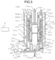
- FIG. 3 is a schematic cross-sectional view of the fuel processing device according to this embodiment.
- the up-and-down direction of FIG. 3 represents a vertical direction.
- the merging portion 200 in this embodiment is formed between the flame tube wall 503 and the inner wall 501.
- the combustion gas flow path 401 is formed below the merging portion 200 in the space between the flame tube wall 503 and the inner wall 501.
- a downstream portion 403b of the catalyst layer outer peripheral flow path 403 is formed above the merging portion 200 in the space between the flame tube wall 503 and the inner wall 501.
- An upstream portion 403a of the catalyst layer outer peripheral flow path 403 is formed in the space between the middle wall 502 and the outer wall 504.
- the downstream portion 403b is continuous with the upstream portion 403a through the communication portion 510.
- the downstream portion 403b faces the upstream portion 403a across the second raw material preheating unit 203a and the reforming reaction flow path 402.
- an oxidizing agent distribution regulator 303 is provided in the catalyst layer outer peripheral gas introducing flow path 601.
- the oxidizing agent distribution regulator 303 adjusts the ratio between the flow rate of the combustion supporting gas F56 and the flow rate of the catalyst layer outer peripheral gas F54.
- an orifice plate is used as the oxidizing agent distribution regulator 303.
- the orifice plate is provided so that the pressure loss of the catalyst layer outer peripheral gas F54 in the catalyst layer outer peripheral gas introducing flow path 601 changes.
- An appropriate orifice plate is provided so that the combustion supporting gas F56 and the catalyst layer outer peripheral gas F54 are distributed at a desired ratio between the respective flow rates at the oxidizing agent branching portion 2.
- the other configurations are similar to those of the first embodiment.
- the catalyst layer outer peripheral gas F54 flows upward through the upstream portion 403a of the catalyst layer outer peripheral flow path 403.
- the flow of the catalyst layer outer peripheral gas F54 in the upstream portion 403a is opposite to the flows of the raw material F52 and the reformed gas F53 in the reforming reaction flow path 402 and the flow of the raw material F52 in the second raw material preheating unit 203a.
- the catalyst layer outer peripheral gas F54 flowing through the upstream portion 403a gives thermal energy to the raw material F52 and the reformed gas F53 flowing through the reforming reaction flow path 402 from the outer peripheral side, and gives thermal energy to the raw material F52 flowing through the second raw material preheating unit 203a from the outer peripheral side.
- the flow of the catalyst layer outer peripheral gas F54 in the downstream portion 403b is parallel to the flows of the raw material F52 and the reformed gas F53 in the reforming reaction flow path 402 and the flow of the raw material F52 in the second raw material preheating unit 203a.
- the catalyst layer outer peripheral gas F54 flowing through the downstream portion 403b gives thermal energy to the raw material F52 flowing through the second raw material preheating unit 203a from the inner peripheral side, and gives thermal energy to the raw material F52 and the reformed gas F53 flowing through the reforming reaction flow path 402 from the inner peripheral side.
- FIG. 4 is a graph for showing the temperature distribution of the fuel processing device according to this embodiment.
- the horizontal axis and the vertical axis in FIG. 4 are similar to the horizontal axis and the vertical axis in FIG. 2 .
- the merging portion 200 in this embodiment is provided at a position larger than 0 and smaller than 1 in the center axis 100a direction, and is provided on the inner peripheral side with respect to the reforming reaction flow path 402.
- the communication portion 510 is provided at a position smaller than 0 in the center axis 100a direction.
- the solid line in FIG. 4 represents the temperature of the combustion gas F51.
- the long-dashed broken line in FIG. 4 represents the temperature of the catalyst layer outer peripheral gas F54.
- the short-dashed broken line in FIG. 4 represents the temperature of the raw material F52 and the reformed gas F53.
- the thermal energy of the combustion gas F51 becomes smaller.
- the thermal energy of the catalyst layer outer peripheral gas F54 becomes larger.
- the temperature of the catalyst layer outer peripheral gas F54 does not decrease as in the temperature of the combustion gas F51, even when the position in the center axis 100a direction approaches the inlet of the reforming reaction flow path 402.
- the temperature difference between the catalyst layer outer peripheral gas F54 and the raw material F52 and the reformed gas F53 is larger than the temperature difference between the combustion gas F51 and the raw material F52 and the reformed gas F53.
- the temperature of the reforming reaction flow path 402 is non-uniform in the radial direction of the fuel processing device 100.
- the catalyst layer outer peripheral gas F54 first flows through the upstream portion 403a of the catalyst layer outer peripheral flow path 403.
- the flow of the catalyst layer outer peripheral gas F54 at the upstream portion 403a is opposite to the flows of the raw material F52 and the reformed gas F53.
- the catalyst layer outer peripheral gas F54 at the upstream portion 403a gives thermal energy to the raw material F52 and the reformed gas F53 from the outer peripheral side.
- the section from the point A to the point B in FIG. 4 represents the temperature distribution of the catalyst layer outer peripheral gas F54 at the upstream portion 403a.
- the catalyst layer outer peripheral gas F54 is reversed at the communication portion 510 to flow around on the inner peripheral side with respect to the reforming reaction flow path 402 and flow into the downstream portion 403b of the catalyst layer outer peripheral flow path 403.
- the flow of the catalyst layer outer peripheral gas F54 at the downstream portion 403b is parallel to the flows of the raw material F52 and the reformed gas F53.
- the catalyst layer outer peripheral gas F54 at the downstream portion 403b gives thermal energy to the raw material F52 and the reformed gas F53 from the inner peripheral side.
- the section from the point B to the point C in FIG. 4 represents the temperature distribution of the catalyst layer outer peripheral gas F54 at the downstream portion 403b.
- heat is given to the downstream-side portion of the reforming reaction flow path 402 in the flows of the raw material F52 and the reformed gas F53 by the catalyst layer outer peripheral gas F54 from the outer peripheral side, and heat is given thereto by the combustion gas F51 from the inner peripheral side.
- Heat is given to the upstream-side portion of the reforming reaction flow path 402 by the catalyst layer outer peripheral gas F54 flowing through the upstream portion 403a from the outer peripheral side, and heat is given thereto by the catalyst layer outer peripheral gas F54 flowing through the downstream portion 403b from the inner peripheral side.
- the temperature difference between the catalyst layer outer peripheral gas F54 at the downstream portion 403b and the raw material F52 and the reformed gas F53 can be secured.
- the heat transfer property of the fuel processing device 100 can be improved.
- the distribution ratio of the combustion supporting gas F56 is small in thermal energy, the thermal efficiency of the fuel processing device 100 can be improved.
- the temperature of the reforming reaction flow path 402 can be made uniform in the radial direction of the fuel processing device 100.
- the distribution ratio of the combustion supporting gas F56 is small in thermal energy, the reformed gas F53 with a small composition variation due to a reaction can be obtained.
- the temperature of the combustion gas F51 at the merging portion 200 and the temperature of the catalyst layer outer peripheral gas F54 at the merging portion 200 can be brought closer to each other.
- the loss of the thermal energy can be reduced. Accordingly, even when the distribution ratio of the combustion supporting gas F56 is small in thermal energy, the thermal efficiency of the fuel processing device 100 can be improved.
- the combustion reaction can be performed in a range of an appropriate oxygen ratio, thereby being capable of attaining stable complete combustion. Further, the heat transfer property is improved in this embodiment, thereby being capable of attaining a reduction in size of the fuel processing device 100.
- the oxidizing agent distribution regulator 303 is provided in the catalyst layer outer peripheral gas introducing flow path 601, but the configuration is not limited thereto.
- the distribution ratio between the combustion supporting gas F56 and the catalyst layer outer peripheral gas F54 is determined based on the ratio between the pressure loss of the flow path of the combustion supporting gas F56 and the pressure loss of the flow path of the catalyst layer outer peripheral gas F54.
- the oxidizing agent distribution regulator 303 may be provided in the combustion supporting gas flow path 602, and or may be provided in each of the combustion supporting gas flow path 602 and the catalyst layer outer peripheral gas introducing flow path 601.
- the oxidizing agent distribution regulator 303 configured to determine the distribution ratio between the combustion supporting gas F56 and the catalyst layer outer peripheral gas F54 is provided.
- the temperature of the reforming reaction flow path 402 can be made uniform in the radial direction, thereby being capable of obtaining the reformed gas F53 with a small composition variation due to a reaction.
- the catalyst layer outer peripheral flow path 403 includes the upstream portion 403a and the downstream portion 403b.
- the upstream portion 403a is formed on the outer peripheral side with respect to the middle wall 502.
- the downstream portion 403b is formed on the inner peripheral side with respect to the inner wall 501.
- the merging portion 200 is located on the inner peripheral side with respect to the inner wall 501.
- the upstream portion 403a and the downstream portion 403b face each other across the reforming reaction flow path 402. According to this configuration, even when the distribution ratio of the combustion supporting gas F56 is small in thermal energy, the reformed gas F53 with a small composition variation due to a reaction can be obtained, and the thermal efficiency of the fuel processing device 100 can be improved.
- FIG. 5 is a schematic cross-sectional view of the fuel processing device according to this embodiment.
- the up-and-down direction of FIG. 5 represents a vertical direction.
- the merging portion 200 in this embodiment is formed between the middle wall 502 and the outer wall 504.
- the catalyst layer outer peripheral flow path 403 is formed below the merging portion 200 in the space between the middle wall 502 and the outer wall 504.
- a downstream portion 401b of the combustion gas flow path 401 is formed above the merging portion 200 in the space between the middle wall 502 and the outer wall 504.
- An upstream portion 401a of the combustion gas flow path 401 is formed in the space between the flame tube wall 503 and the inner wall 501.
- the downstream portion 401b is continuous with the upstream portion 401a through the communication portion 510.
- the downstream portion 401b faces the upstream portion 401a across the second raw material preheating unit 203a and the reforming reaction flow path 402.
- the other configurations are similar to those of the first embodiment.
- the combustion gas F51 flows upward through the upstream portion 401a of the combustion gas flow path 401.
- the flow of the combustion gas F51 in the upstream portion 401a is opposite to the flows of the raw material F52 and the reformed gas F53 in the reforming reaction flow path 402 and the flow of the raw material F52 in the second raw material preheating unit 203a.
- the combustion gas F51 flowing through the upstream portion 401a gives thermal energy to the raw material F52 and the reformed gas F53 flowing through the reforming reaction flow path 402 from the inner peripheral side, and gives thermal energy to the raw material F52 flowing through the second raw material preheating unit 203a from the inner peripheral side.
- the combustion gas F51 flows upward through the upstream portion 401a, and then passes through the communication portion 510 to flow around on the outer peripheral side with respect to the second raw material preheating unit 203a and the reforming reaction flow path 402 and flow into the downstream portion 401b. At the downstream portion 401b, the combustion gas F51 flows downward.
- the flow of the combustion gas F51 in the downstream portion 401b is parallel to the flows of the raw material F52 and the reformed gas F53 in the reforming reaction flow path 402 and the flow of the raw material F52 in the second raw material preheating unit 203a.
- the combustion gas F51 flowing through the downstream portion 401b gives thermal energy to the raw material F52 flowing through the second raw material preheating unit 203a from the outer peripheral side, and gives thermal energy to the raw material F52 and the reformed gas F53 flowing through the reforming reaction flow path 402 from the outer peripheral side.
- the combustion gas F51 flowing through the downstream portion 401b merges with the catalyst layer outer peripheral gas F54 at the merging portion 200.
- the merged gas flows out to the outside from the exhaust gas flow path 404 as the exhaust gas F58.
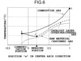
- FIG. 6 is a graph for showing the temperature distribution of the fuel processing device according to this embodiment.
- the horizontal axis and the vertical axis in FIG. 6 are similar to the horizontal axis and the vertical axis in FIG. 2 .
- the merging portion 200 in this embodiment is provided at a position larger than 0 and smaller than 1 in the center axis 100a direction, and is provided on the outer peripheral side with respect to the reforming reaction flow path 402.
- the solid line in FIG. 6 represents the temperature of the combustion gas F51.
- the long-dashed broken line in FIG. 6 represents the temperature of the catalyst layer outer peripheral gas F54.
- the short-dashed broken line in FIG. 6 represents the temperature of the raw material F52 and the reformed gas F53.
- the thermal energy of the catalyst layer outer peripheral gas F54 becomes smaller.
- the thermal energy of the combustion gas F51 becomes larger.
- the temperature of the catalyst layer outer peripheral gas F54 becomes significantly smaller than the temperature of the combustion gas F51.
- the temperature difference between the catalyst layer outer peripheral gas F54 and the raw material F52 and the reformed gas F53 decreases, with the result that the heat transfer property is degraded.
- the temperature of the combustion gas F51 does not decrease as in the temperature of the catalyst layer outer peripheral gas F54, even when the position in the center axis 100a direction approaches the inlet of the reforming reaction flow path 402.
- the temperature difference between the combustion gas F51 and the raw material F52 and the reformed gas F53 is larger than the temperature difference between the catalyst layer outer peripheral gas F54 and the raw material F52 and the reformed gas F53.
- the temperature of the reforming reaction flow path 402 is non-uniform in the radial direction of the fuel processing device 100.
- the combustion gas F51 first flows through the upstream portion 401a of the combustion gas flow path 401.
- the flow of the combustion gas F51 at the upstream portion 401a is opposite to the flows of the raw material F52 and the reformed gas F53.
- the combustion gas F51 at the upstream portion 401a gives thermal energy to the raw material F52 and the reformed gas F53 from the inner peripheral side.
- the section from the point D to the point E in FIG. 6 represents the temperature distribution of the combustion gas F51 at the upstream portion 401a.
- the combustion gas F51 is reversed at the communication portion 510 to flow around on the outer peripheral side with respect to the reforming reaction flow path 402 and flow into the downstream portion 401b of the combustion gas flow path 401.
- the flow of the combustion gas F51 at the downstream portion 401b is parallel to the flows of the raw material F52 and the reformed gas F53.
- the combustion gas F51 at the downstream portion 401b gives thermal energy to the raw material F52 and the reformed gas F53 from the outer peripheral side.
- the section from the point E to the point F in FIG. 6 represents the temperature distribution of the combustion gas F51 at the downstream portion 401b.
- heat is given to the downstream-side portion of the reforming reaction flow path 402 in the flows of the raw material F52 and the reformed gas F53 by the combustion gas F51 from the inner peripheral side, and heat is given thereto by the catalyst layer outer peripheral gas F54 from the outer peripheral side.
- Heat is given to the upstream-side portion of the reforming reaction flow path 402 by the combustion gas F51 flowing through the upstream portion 401a from the inner peripheral side, and heat is given thereto by the combustion gas F51 flowing through the downstream portion 401b from the outer peripheral side.
- the temperature difference between the combustion gas F51 at the downstream portion 401b and the raw material F52 and the reformed gas F53 can be secured.
- the heat transfer property of the fuel processing device 100 can be improved.
- the thermal efficiency of the fuel processing device 100 can be improved.
- the temperature of the reforming reaction flow path 402 can be made uniform in the radial direction of the fuel processing device 100.
- the distribution ratio of the catalyst layer outer peripheral gas F54 is small in thermal energy, the reformed gas F53 with a small composition variation due to a reaction can be obtained.
- the temperature of the combustion gas F51 at the merging portion 200 and the temperature of the catalyst layer outer peripheral gas F54 at the merging portion 200 can be brought closer to each other.
- the loss of the thermal energy can be reduced. Accordingly, even when the distribution ratio of the catalyst layer outer peripheral gas F54 is small in thermal energy, the thermal efficiency of the fuel processing device 100 can be improved.
- the combustion reaction can be performed in a range of an appropriate oxygen ratio, thereby being capable of attaining stable complete combustion. Further, the heat transfer property is improved, thereby being capable of attaining a reduction in size of the fuel processing device 100.
- the combustion gas flow path 401 includes the upstream portion 401a and the downstream portion 401b.
- the upstream portion 401a is formed on the inner peripheral side with respect to the inner wall 501.
- the downstream portion 401b is formed on the outer peripheral side with respect to the middle wall 502.
- the merging portion 200 is located on the outer peripheral side with respect to the middle wall 502.
- the upstream portion 401a of the combustion gas flow path 401 and the downstream portion 401b of the combustion gas flow path 401 face each other across the reforming reaction flow path 402. According to this configuration, even when the distribution ratio of the catalyst layer outer peripheral gas F54 is small in thermal energy, the reformed gas F53 with a small composition variation due to a reaction can be obtained, and the thermal efficiency of the fuel processing device 100 can be improved.
- FIG. 7 is a schematic cross-sectional view of the fuel processing device according to this embodiment.
- the up-and-down direction of FIG. 7 represents a vertical direction.
- the first raw material preheating unit 203 penetrates the upper surface wall 506 and the closing wall 505, and passes through the communication portion 510 to be connected to the second raw material preheating unit 203a.
- the first raw material preheating unit 203 is bent in a helical shape about the center axis 100a in the communication portion 510.
- the first raw material preheating unit 203 is formed of a circular pipe.
- the first raw material preheating unit 203 is configured to absorb a change in distance between the upper surface wall 506 and the closing wall 505 when the helical portion extends and contracts in the center axis 100a direction.
- the other configurations are similar to those of the second embodiment.
- the operation of the fuel processing device is described.
- the raw material F52 passes through the first raw material preheating unit 203 and the second raw material preheating unit 203a before being introduced into the reforming reaction flow path 402.
- the raw material F52 receives thermal energy from the catalyst layer outer peripheral gas F54 flowing through the communication portion 510.
- the raw material F52 is preheated.
- the raw material F52 receives thermal energy from the catalyst layer outer peripheral gas F54 flowing through the upstream portion 403a of the catalyst layer outer peripheral flow path 403, and receives thermal energy from the catalyst layer outer peripheral gas F54 flowing through the downstream portion 403b of the catalyst layer outer peripheral flow path 403.
- the raw material F52 is further preheated.
- the preheated raw material F52 flows into the reforming reaction flow path 402.
- the fuel processing device 100 includes the combustor 1 at a lower portion on the center axis 100a.
- a distribution temperature is formed that, in the up-and-down direction, the temperature is higher on the lower portion side, and in the radial direction, the temperature is higher on the inner peripheral side.
- the reforming reaction flow path 402 such a generally one-dimensional temperature distribution that the temperature is higher on the lower portion side is formed.
- the first raw material preheating unit 203 is formed in a helical shape so that thermal expansion of the inner wall 501 and the middle wall 502 can be absorbed by the first raw material preheating unit 203.
- the first raw material preheating unit 203 is formed in a helical shape in the communication portion 510, thereby being capable of increasing the heat transfer area of the first raw material preheating unit 203. With this, the heat transfer performance can be improved as compared to a case in which the raw material F52 is preheated only by the second raw material preheating unit 203a.
- the first raw material preheating unit 203 is formed in a helical shape so that thermal expansion of the inner wall 501 and the middle wall 502 can be absorbed by the first raw material preheating unit 203. With this, the reliability of the structure member of the fuel processing device 100 can be improved.
- FIG. 8 is a schematic cross-sectional view of a fuel processing device according to the modification example of this embodiment.
- the first raw material preheating unit 203 has a structure that is extendable and contractable in the center axis 100a direction at least between the upper surface wall 506 and the closing wall 505.
- a bellows tube having stretchability is used as the first raw material preheating unit 203 between the upper surface wall 506 and the closing wall 505.
- the other configurations are similar to those of the second embodiment.
- the length of the first raw material preheating unit 203 in the center axis 100a direction can be made shorter than that of the configuration illustrated in FIG. 7 , thereby being capable of reducing the size of the fuel processing device 100.
- the first raw material preheating unit 203 may meander along the circumferential direction of the fuel processing device 100 so as to secure a large heat transfer area between the first raw material preheating unit 203 and the catalyst layer outer peripheral gas F54.
- the first raw material preheating unit 203 has a structure that is extendable and contractable. According to this configuration, thermal expansion of the inner wall 501 and the middle wall 502 can be absorbed by the first raw material preheating unit 203, thereby being capable of improving the reliability of the structure member of the fuel processing device 100.
- FIG. 9 is a schematic cross-sectional view of the fuel processing device according to this embodiment.
- the up-and-down direction of FIG. 9 represents a vertical direction.
- the fuel processing device 100 includes a cathode gas preheating unit 204.
- a cathode gas F60 flows into the cathode gas preheating unit 204 from the outside of the fuel processing device 100.
- the cathode gas preheating unit 204 the cathode gas F60 is preheated by radiation heat from the combustion space 202 and heat transfer from the exhaust gas F58.
- the preheated cathode gas F60 is supplied to the heating source outside the fuel processing device 100 as the preheated cathode gas F61.
- the heating source the high-temperature fuel cell (not shown) is used.
- the cathode gas preheating unit 204 includes the exhaust gas flow path 404, a preheating flow path 204a, and an exhaust flow path 204b.
- the exhaust gas flow path 404 is formed above the merging portion 200.
- the exhaust gas flow path 404 is formed in an annular shape having the same diameter as that of the combustion gas flow path 401 in horizontal cross section.
- the exhaust gas flow path 404 extends in the up-and-down direction.
- the exhaust gas F58 in which the combustion gas F51 and the catalyst layer outer peripheral gas F54 have merged with each other flows upward through the exhaust gas flow path 404.
- the preheating flow path 204a is arranged on the inner peripheral side with respect to the combustion gas flow path 401 and the exhaust gas flow path 404.
- the preheating flow path 204a is formed in an annular shape in horizontal cross section.
- the preheating flow path 204a extends in the up-and-down direction.
- the preheating flow path 204a is arranged on a side opposite to the radiation heat transfer space 201 across the flame partition plate 3, that is, is arranged above the flame partition plate 3.
- the preheating flow path 204a is adjacent to the combustion gas flow path 401 and the exhaust gas flow path 404 across the flame tube wall 503.
- the cathode gas F60 supplied from the outside of the fuel processing device 100 flows downward through the preheating flow path 204a.
- the flow of the cathode gas F60 in the preheating flow path 204a is opposite to the flow of the combustion gas F51 in the combustion gas flow path 401 and the flow of the exhaust gas F58 in the exhaust gas flow path 404.
- the cathode gas F60 in the preheating flow path 204a is preheated through heat exchange between the exhaust gas F58 in the exhaust gas flow path 404 and the combustion gas F51 in the combustion gas flow path 401.
- the exhaust flow path 204b is arranged on the inner peripheral side with respect to the preheating flow path 204a.
- the exhaust flow path 204b extends in the up-and-down direction.
- a lower end portion of the exhaust flow path 204b is connected to a lower end portion of the preheating flow path 204a.
- the preheated cathode gas F61 preheated in the preheating flow path 204a flows upward through the exhaust flow path 204b.
- the preheated cathode gas F61 having flowed out from the exhaust flow path 204b is supplied to the heating source outside the fuel processing device 100.
- the first raw material preheating unit 203 has a structure that is extendable and contractable in the center axis 100a direction between the upper surface wall 506 and the closing wall 505.
- the other configurations are similar to those of the first embodiment.
- the raw material F52 passes through the first raw material preheating unit 203 and the second raw material preheating unit 203a to be introduced into the reforming reaction flow path 402.
- the raw material F52 of the reforming reaction flow path 402 is heated from the inner peripheral side by the combustion gas F51 in the combustion gas flow path 401.
- the raw material F52 of the reforming reaction flow path 402 is heated also from the outer peripheral side by the catalyst layer outer peripheral gas F54 in the catalyst layer outer peripheral flow path 403.
- the reformed gas F53 is generated from the raw material F52 due to a catalytic action of the reforming catalyst 5.
- the combustion gas F51 of about 700 °C to 1,200 °C is generated.
- the radiation heat transfer space 201 heat transfer is promoted by radiation heat from flame of the combustor 1, convection heat transfer by the combustion gas F51, or the like to heat the flame partition plate 3.
- the combustion gas F51 flows into the combustion gas flow path 401.
- the combustion gas F51 in the combustion gas flow path 401 merges with the catalyst layer outer peripheral gas F54 at the merging portion 200 to turn into the exhaust gas F58.
- the exhaust gas F58 flows through the exhaust gas flow path 404.
- the cathode gas F60 is supplied to the cathode gas preheating unit 204 from the outside of the fuel processing device 100.
- the cathode gas F60 flows into the preheating flow path 204a.
- the cathode gas F60 in the preheating flow path 204a is preheated through heat exchange between the exhaust gas F58 in the exhaust gas flow path 404 and the combustion gas F51 in the combustion gas flow path 401.
- the cathode gas F60 receives thermal energy from the flame partition plate 3 to be further preheated and increased in temperature to about 550 °C. With this, the cathode gas F60 turns into the preheated cathode gas F61.
- the preheated cathode gas F61 passes through the exhaust flow path 204b to flow out from the fuel processing device 100, and is supplied to the heating source.
- Heat is given to the cathode gas F60 from the exhaust gas F58 so that the temperature of the exhaust gas F58 decreases to, for example, about 65 °C.
- the exhaust gas F58 decreased in temperature is exhausted to the outside of the fuel processing device 100.
- the thermal energy of the exhaust gas F58 is collected in the cathode gas preheating unit 204 so that an operation with thermal efficiency higher than that of the fuel processing device 100 of each of the first embodiment to the fourth embodiment can be enabled.
- the thermal energy collected in the cathode gas preheating unit 204 is used for preheating the cathode gas F60.
- the preheated cathode gas F60 is supplied to the fuel cell or the like.
- the exhaust gas of the fuel cell is used as the oxidizing agent F50. With this, heat can be effectively utilized in the fuel cell system.
- the fuel processing device 100 has a temperature increase function of the cathode gas, thereby being capable of attaining a reduction in size and higher efficiency of the fuel cell system.
- the cathode gas F60 is preheated through heat exchange between the combustion gas F51 in the combustion gas flow path 401 and the exhaust gas F58 in the exhaust gas flow path 404, but the configuration is not limited thereto.
- the cathode gas F60 may be preheated only through heat exchange with the exhaust gas F58 in the exhaust gas flow path 404.
- a heat insulating material or the like may be provided so as to block heat transfer from the combustion gas flow path 401 to the cathode gas preheating unit 204.
- the heat shield material 6 is not provided, but a heat shield material having an appropriate thickness may be provided in accordance with a temperature required for the preheated cathode gas F61.
- the fuel processing device 100 further includes the cathode gas preheating unit 204.
- the cathode gas preheating unit 204 is configured to preheat the cathode gas F60 to be supplied to the fuel cell through heat transfer from the exhaust gas F58. According to this configuration, heat can be effectively utilized in the fuel cell system.
- the cathode gas preheating unit 204 is further configured to preheat the cathode gas F60 by radiation heat from the combustion space 202.
- FIG. 10 is a schematic cross-sectional view of the fuel processing device according to this embodiment.
- the up-and-down direction of FIG. 10 represents a vertical direction.
- the cathode gas preheating unit 204 includes a main body portion 204c and a box body heat exchange unit 205.
- the main body portion 204c has the same configuration as that of the cathode gas preheating unit 204 in the fifth embodiment.
- the box body heat exchange unit 205 is formed in a box body shape.
- the reforming unit 110, the combustion unit 120, and the main body portion 204c of the cathode gas preheating unit 204 are accommodated in the internal space of the box body heat exchange unit 205. That is, the reforming unit 110, the combustion unit 120, and the main body portion 204c of the cathode gas preheating unit 204 are surrounded by the box body heat exchange unit 205.
- the box body heat exchange unit 205 includes a preheating flow path 205a and an exhaust gas flow path 205b.
- the exhaust gas flow path 205b is provided on the internal space side of the box body heat exchange unit 205 with respect to the preheating flow path 205a.
- the preheating flow path 205a is connected to the upstream side of the preheating flow path 204a.
- the cathode gas F60 before flowing into the preheating flow path 204a flows through the preheating flow path 205a.
- the exhaust gas flow path 205b is connected to the downstream side of the exhaust gas flow path 404.
- the exhaust gas F58 having flowed out from the exhaust gas flow path 404 flows through the exhaust gas flow path 205b.
- heat exchange between the cathode gas F60 in the preheating flow path 205a and the exhaust gas F58 in the exhaust gas flow path 205b is performed.
- a fuel cell 10 is arranged in the internal space of the box body heat exchange unit 205. That is, the fuel cell 10 is surrounded by the box body heat exchange unit 205.
- the fuel cell 10 includes an anode 11 and a cathode 12.
- the anode 11 and the cathode 12 are partitioned from each other by an electrolyte.
- the inlet of the anode 11 is connected to the reforming reaction flow path 402.
- the outlet of the anode 11 is connected to the combustor 1.
- the inlet of the cathode 12 is connected to the exhaust flow path 204b of the cathode gas preheating unit 204.
- the outlet of the cathode 12 is connected to the oxidizing agent flow path 600.
- a heat insulating material that suppresses a heat interference between devices and heat radiation is arranged inside and outside the box body heat exchange unit 205 as required.
- the exhaust gas F58 having flowed out from the exhaust gas flow path 404 flows into the exhaust gas flow path 205b of the box body heat exchange unit 205.
- the exhaust gas F58 in the exhaust gas flow path 205b gives thermal energy to the cathode gas F60 in the preheating flow path 205a. With this, the temperature of the exhaust gas F58 decreases.
- the exhaust gas F58 having flowed through the exhaust gas flow path 205b is exhausted to the outside from the box body heat exchange unit 205.
- the cathode gas F60 flows into the preheating flow path 205a of the box body heat exchange unit 205 from the outside.
- the cathode gas F60 in the preheating flow path 205a receives thermal energy from the exhaust gas F58 of the exhaust gas flow path 205b.
- the cathode gas F60 having flowed out from the preheating flow path 205a of the box body heat exchange unit 205 flows into the preheating flow path 204a of the main body portion 204c.
- the cathode gas F60 in the preheating flow path 204a receives thermal energy from the exhaust gas F58 and the combustion gas F51 and the flame partition plate 3 to turn into the preheated cathode gas F61.
- the preheated cathode gas F61 passes through the exhaust flow path 204b to flow out from the main body portion 204c, and is supplied to the cathode 12 of the fuel cell 10.
- the cathode 12 oxygen required for a battery reaction of the fuel cell 10 is consumed. With this, the preheated cathode gas F61 turns into a cathode off-gas.
- the cathode off-gas flows out from the cathode 12, and flows into the oxidizing agent flow path 600 as the oxidizing agent F50.
- the reformed gas F53 having flowed out from the reforming reaction flow path 402 is supplied to the anode 11 of the fuel cell 10.
- hydrogen required for a battery reaction of the fuel cell 10 is consumed.
- the reformed gas F53 turns into an anode off-gas.
- the anode off-gas flows out from the anode 11. At least a part of the anode off-gas having flowed out from the anode 11 is supplied to the combustor 1 as the combustion fuel F55.
- heat exchange between the cathode gas F60 and the exhaust gas F58 is performed in the box body heat exchange unit 205.
- the temperature difference between the cathode gas F60 and the exhaust gas F58 is relatively small, the heat transfer area between the cathode gas F60 and the exhaust gas F58 can be largely secured, thereby being capable of effectively performing heat recovery.
- the fuel cell 10, the reforming unit 110 of the fuel processing device 100, the combustion unit 120, and the main body portion 204c are surrounded by the box body heat exchange unit 205. With this, heat radiation from the fuel cell 10 and the fuel processing device 100 can be suppressed.
- the heat transfer area between the cathode gas F60 and the exhaust gas F58 can be largely secured in the box body heat exchange unit 205, thereby being capable of reducing the size of the main body portion 204c of the cathode gas preheating unit 204.
- higher efficiency and a reduction in size of the fuel processing device for a fuel cell can be attained.
- the configuration of the fuel cell system is not limited to the configuration illustrated in FIG. 10 .
- a part of the anode off-gas may be used as the combustion fuel F55, and the remaining anode off-gas may be recycled as a part of the raw material F52.
- the flow path of the anode off-gas is configured to condense a part of the contained water vapor of the anode off-gas, and then, branch the anode off-gas.
- the thermal energy of the anode off-gas may be collected, for example, to use for vaporization heat for generating water vapor.
- the cathode gas preheating unit 204 includes the box body heat exchange unit 205.
- the box body heat exchange unit 205 surrounds the combustion unit 120 and the reforming unit 110, and the fuel cell 10.
- heat exchange between the exhaust gas F58 and the cathode gas F60 is performed.
- the heat transfer area between the cathode gas F60 and the exhaust gas F58 can be largely secured, thereby being capable of effectively performing heat recovery. Further, heat radiation from the fuel cell 10 and the fuel processing device 100 can be suppressed.
- the flow paths such as the catalyst layer outer peripheral flow path 403, the combustion gas flow path 401, the exhaust gas flow path 404, the preheating flow path 205a, the exhaust gas flow path 205b, and the preheating flow path 204a, are described as being like spaces, but those flow paths may be replaced with heat transfer promoting structures, such as a fin structure and particle filling.
- the heat transfer performance can be further improved, thereby being capable of attaining higher efficiency and a reduction in size of the fuel processing device 100.
- at least a part of the second raw material preheating unit 203a located on the upstream side of the reforming reaction flow path 402 may be formed as a heat transfer promoting structure. With this, heat transfer performance to the raw material F52 is improved, thereby being capable of attaining the fuel processing device 100 which has high efficiency and is small in size.
- a unit for reducing a dynamic pressure of a flow for example, a baffle plate
- the second raw material preheating unit 203a into which the raw material F52 flows from the first raw material preheating unit 203 in order to attain uniform gas distribution in the circumferential direction in the second raw material preheating unit 203a.
- this description is not limited only to the second raw material preheating unit 203a, and, for example, also applies to a portion at which the catalyst layer outer peripheral gas F54 flows into the catalyst layer outer peripheral flow path 403.
Landscapes
- Chemical & Material Sciences (AREA)
- Engineering & Computer Science (AREA)
- Chemical Kinetics & Catalysis (AREA)
- General Chemical & Material Sciences (AREA)
- Sustainable Energy (AREA)
- Sustainable Development (AREA)
- Manufacturing & Machinery (AREA)
- Electrochemistry (AREA)
- Life Sciences & Earth Sciences (AREA)
- Combustion & Propulsion (AREA)
- Organic Chemistry (AREA)
- Physics & Mathematics (AREA)
- Fluid Mechanics (AREA)
- Health & Medical Sciences (AREA)
- General Health & Medical Sciences (AREA)
- Inorganic Chemistry (AREA)
- Hydrogen, Water And Hydrids (AREA)
- Fuel Cell (AREA)
Abstract
Description
- This invention relates to a fuel processing device.
- A fuel processing device is used in a fuel cell system, a hydrogen station, or the like. The fuel processing device generates a reformed gas containing hydrogen by a reforming reaction of a hydrocarbon-based raw material such as a natural gas, alcohols, or ammonia. The reforming reaction is an endothermic reaction, and hence thermal energy is required for the reforming reaction. Thus, the fuel processing device includes a combustor configured to generate thermal energy.
- In
Patent Literature 1, a hydrogen generating device is described. This hydrogen generating device includes a reformer, a combustor, and an exhaust gas path. A reforming catalyst is filled inside the reformer. The reformer reforms a fuel to generate a reformed gas containing hydrogen. The combustor heats the reformer. The exhaust gas path covers a periphery of an outer wall of the reformer. A combustion exhaust gas from the combustor flows through the exhaust gas path. - [PTL 1]
JP 2017 105 695 A - In the above-mentioned hydrogen generating device, the reformer is mainly heated from an outer peripheral side by the combustion exhaust gas, and hence there is a limitation in the heat transfer area between the reformer and the combustion exhaust gas. Thus, in the above-mentioned hydrogen generating device, there is a problem in that thermal efficiency is degraded.
- This invention has been made in order to solve the problems as described above, and has an object to provide a fuel processing device that can obtain a higher thermal efficiency.
- According to this invention, there is provided a fuel processing device including: a reforming unit configured to generate a reformed gas from a raw material; and a combustion unit configured to combust a fuel and a combustion supporting gas in a combustion space to generate a combustion gas. The reforming unit includes: a first tubular wall; and a second tubular wall arranged on an outer peripheral side with respect to the first tubular wall.
- A reforming reaction flow path is formed between the first tubular wall and the second tubular wall, the reforming reaction flow path being configured to be filled with a reforming catalyst and to allow the raw material and the reformed gas to flow through the reforming reaction flow path. A combustion gas flow path configured to allow the combustion gas to flow through the combustion gas flow path is formed on an inner peripheral side with respect to the first tubular wall. The combustion gas flow path is adjacent to the reforming reaction flow path across the first tubular wall.
- An outer peripheral flow path configured to allow an outer peripheral gas to flow through the outer peripheral flow path is formed on an outer peripheral side with respect to the second tubular wall. The outer peripheral flow path is adjacent to the reforming reaction flow path across the second tubular wall.
- The fuel processing device further includes: a merging portion configured to allow the combustion gas having flowed through the combustion gas flow path and the outer peripheral gas having flowed through the outer peripheral flow path to merge with each other; an exhaust gas flow path configured to allow the combustion gas and the outer peripheral gas that have merged at the merging portion to flow through the exhaust gas flow path as an exhaust gas; an oxidizing agent flow path configured to allow an oxidizing agent supplied from a heating source to pass through the oxidizing agent flow path; an oxidizing agent branching portion provided in the oxidizing agent flow path; a combustion supporting gas flow path that connects between the oxidizing agent branching portion and the combustion unit and is configured to allow a part of the oxidizing agent to flow through the combustion supporting gas flow path as the combustion supporting gas; and an outer peripheral gas introducing flow path that connects between the oxidizing agent branching portion and the outer peripheral flow path and is configured to allow the other part of the oxidizing agent to flow through the outer peripheral gas introducing flow path as the outer peripheral gas.
- According to this invention, in the fuel processing device, a higher thermal efficiency can be obtained.
-
-
FIG. 1 is a schematic cross-sectional view of a fuel processing device according to a first embodiment. -
FIG. 2 is a graph for showing a temperature distribution of the fuel processing device according to the first embodiment. -
FIG. 3 is a schematic cross-sectional view of a fuel processing device according to a second embodiment. -
FIG. 4 is a graph for showing a temperature distribution of the fuel processing device according to the second embodiment. -
FIG. 5 is a schematic cross-sectional view of a fuel processing device according to a third embodiment. -
FIG. 6 is a graph for showing a temperature distribution of the fuel processing device according to the third embodiment. -
FIG. 7 is a schematic cross-sectional view of a fuel processing device according to a fourth embodiment. -
FIG. 8 is a schematic cross-sectional view of a fuel processing device according to a modification example of the fourth embodiment. -
FIG. 9 is a schematic cross-sectional view of a fuel processing device according to a fifth embodiment. -
FIG. 10 is a schematic cross-sectional view of a fuel processing device according to a sixth embodiment. - A fuel processing device according to a first embodiment is described.
FIG. 1 is a schematic cross-sectional view of the fuel processing device according to this embodiment. The up-and-down direction ofFIG. 1 represents a vertical direction. - As illustrated in
FIG. 1 , afuel processing device 100 has a cylindrical shape about a center axis 100a. The center axis 100a extends in the up-and-down direction. Thefuel processing device 100 includes a reformingunit 110 and acombustion unit 120. Thecombustion unit 120 is provided below the reformingunit 110. Thecombustion unit 120 generates a combustion gas F51 for heating the reformingunit 110. - The reforming
unit 110 has a multiple tube structure including aflame tube wall 503, aninner wall 501, amiddle wall 502, and anouter wall 504. Each of theflame tube wall 503, theinner wall 501, themiddle wall 502, and theouter wall 504 has a cylindrical shape about the center axis 100a. Theinner wall 501 is arranged on the outer peripheral side with respect to theflame tube wall 503 so as to surround theflame tube wall 503. - The
middle wall 502 is arranged on the outer peripheral side with respect to theinner wall 501 so as to surround theinner wall 501. Theouter wall 504 is arranged on the outer peripheral side with respect to themiddle wall 502 so as to surround themiddle wall 502. Theinner wall 501 is an example of a first tubular wall. Themiddle wall 502 is an example of a second tubular wall. - A combustion
gas flow path 401 is formed in a space between theflame tube wall 503 and theinner wall 501. The combustiongas flow path 401 is formed in an annular shape in horizontal cross section. The combustiongas flow path 401 extends in the up-and-down direction. The combustion gas F51 flows upward through the combustiongas flow path 401. - An upper end portion of the space between the
inner wall 501 and themiddle wall 502 is closed by aclosing wall 505. Theclosing wall 505 is provided between theinner wall 501 and themiddle wall 502. - A reforming
reaction flow path 402 is formed in a space between theinner wall 501 and themiddle wall 502. The reformingreaction flow path 402 is formed in an annular shape in horizontal cross section. The reformingreaction flow path 402 extends in the up-and-down direction. The reformingreaction flow path 402 is adjacent to the combustiongas flow path 401 across theinner wall 501. A raw material F52 and a reformed gas F53 flow downward through the reformingreaction flow path 402. - A reforming
catalyst 5 is filled in the reformingreaction flow path 402. A catalyst layer is formed in the reformingreaction flow path 402 by the reformingcatalyst 5. An upper end portion of the reformingcatalyst 5 serves as an inlet portion of the reformingreaction flow path 402. A lower end portion of the reformingcatalyst 5 serves as an outlet of the reformingreaction flow path 402. - The raw material F52 is supplied to the reforming
reaction flow path 402 from the outside of thefuel processing device 100. In the reformingreaction flow path 402, the reformed gas F53 is generated from the raw material F52 due to a catalytic action of the reformingcatalyst 5. - On the upstream side with respect to the inlet of the reforming
reaction flow path 402 in the flow of the raw material F52, a first rawmaterial preheating unit 203 and a second raw material preheating unit 203a are provided. The second raw material preheating unit 203a is provided on the downstream side with respect to the first rawmaterial preheating unit 203 in the flow of the raw material F52. - The second raw material preheating unit 203a is formed in the space between the
inner wall 501 and themiddle wall 502. The first rawmaterial preheating unit 203 is formed of a pipe. The first rawmaterial preheating unit 203 passes through anupper surface wall 506 and theclosing wall 505, and is connected to the second raw material preheating unit 203a. - The raw material F52 passes through the first raw
material preheating unit 203 and the second raw material preheating unit 203a in this order to flow into the reformingreaction flow path 402. The reformed gas F53 generated in the reformingreaction flow path 402 flows out to the outside of thefuel processing device 100. - A reformed
gas temperature sensor 9 is provided at the outlet of the reformingreaction flow path 402. The reformedgas temperature sensor 9 detects a temperature of the reformed gas F53 flowing out from the reformingreaction flow path 402, and outputs a detection signal to acontroller 8. - A catalyst layer outer
peripheral flow path 403 is formed in a space between themiddle wall 502 and theouter wall 504. The catalyst layer outerperipheral flow path 403 is formed in an annular shape in horizontal cross section. The catalyst layer outerperipheral flow path 403 extends in the up-and-down direction. The catalyst layer outerperipheral flow path 403 is adjacent to the reformingreaction flow path 402 across themiddle wall 502. A catalyst layer outer peripheral gas F54 flows upward through the catalyst layer outerperipheral flow path 403. - An upper end portion of a space on the inner peripheral side with respect to the
outer wall 504 is closed by theupper surface wall 506. Theupper surface wall 506 is formed in a disk shape about the center axis 100a. Theupper surface wall 506 faces theclosing wall 505 with a gap. The gap between theupper surface wall 506 and theclosing wall 505 serves as acommunication portion 510. The space between theflame tube wall 503 and theinner wall 501 and the space between themiddle wall 502 and theouter wall 504 are in communication with each other through thecommunication portion 510. The first rawmaterial preheating unit 203 passes through thecommunication portion 510. - An exhaust
gas flow path 404 is connected to theupper surface wall 506. The exhaustgas flow path 404 is provided on the center axis 100a of thefuel processing device 100. An exhaust gas F58 flows through the exhaustgas flow path 404. - In a radial direction of the reforming
unit 110, the reformingreaction flow path 402 is sandwiched by the combustiongas flow path 401 and the catalyst layer outerperipheral flow path 403 from both sides. A direction in which the raw material F52 and the reformed gas F53 flow in the reformingreaction flow path 402 is opposite to the direction in which the combustion gas F51 flows in the combustiongas flow path 401 and the direction in which the catalyst layer outer peripheral gas F54 flows in the catalyst layer outerperipheral flow path 403. - That is, the flows of the raw material F52 and the reformed gas F53 in the reforming
reaction flow path 402 are opposite to the flow of the combustion gas F51 in the combustiongas flow path 401 and the flow of the catalyst layer outer peripheral gas F54 in the catalyst layer outerperipheral flow path 403. - Heat exchange is performed through the
inner wall 501 between the combustion gas F51 in the combustiongas flow path 401 and the raw material F52 and the reformed gas F53 in the reformingreaction flow path 402. Heat exchange is performed through themiddle wall 502 between the catalyst layer outer peripheral gas F54 in the catalyst layer outerperipheral flow path 403 and the raw material F52 and the reformed gas F53 in the reformingreaction flow path 402. - Further, similarly to the reforming
reaction flow path 402, the second raw material preheating unit 203a is sandwiched by the combustiongas flow path 401 and the catalyst layer outerperipheral flow path 403 from both sides. Heat exchange is performed through theinner wall 501 between the combustion gas F51 in the combustiongas flow path 401 and the raw material F52 in the second raw material preheating unit 203a. Heat exchange is performed through themiddle wall 502 between the catalyst layer outer peripheral gas F54 in the catalyst layer outerperipheral flow path 403 and the raw material F52 in the second raw material preheating unit 203a. - The catalyst layer outer peripheral gas F54 flows through the
communication portion 510 around the first rawmaterial preheating unit 203. In the first rawmaterial preheating unit 203, heat exchange is performed between the catalyst layer outer peripheral gas F54 and the raw material F52. The first rawmaterial preheating unit 203 may meander along the circumferential direction of thefuel processing device 100 so as to secure a larger heat transfer area between the first rawmaterial preheating unit 203 and the catalyst layer outer peripheral gas F54. - An upper end portion of the internal space of the
flame tube wall 503 is closed by aclosing wall 507. Theclosing wall 507 faces theupper surface wall 506 with a gap. - The
combustion unit 120 includes acombustor 1. Thecombustor 1 is arranged on the center axis 100a. Thecombustor 1 is arranged below theflame tube wall 503. A combustion fuel F55, a combustion raw material F59, and a combustion supporting gas F56 are supplied to thecombustor 1. Thecombustor 1 combusts the combustion fuel F55 or the combustion raw material F59 and the combustion supporting gas F56. With this, flame is formed in acombustion space 202, and the combustion gas F51 is generated. - A
flame partition plate 3 is provided inside theflame tube wall 503. The internal space of theflame tube wall 503 is partitioned into an upper part and a lower part by theflame partition plate 3. Aheat shield material 6 is provided in a space above theflame partition plate 3 and below theclosing wall 507 inside theflame tube wall 503. A space below theflame partition plate 3 inside theflame tube wall 503 serves as a radiationheat transfer space 201. A lower end of theflame tube wall 503 is opened. Theflame partition plate 3 faces thecombustor 1 across the radiationheat transfer space 201. The radiationheat transfer space 201 is surrounded by theflame tube wall 503, theflame partition plate 3, and thecombustor 1. - The
combustion space 202 is formed at a lower portion of the radiationheat transfer space 201. The radiationheat transfer space 201 is connected to a lower end portion of the combustiongas flow path 401. The combustion gas F51 generated by thecombustor 1 passes through thecombustion space 202 and the radiationheat transfer space 201 to flow into the combustiongas flow path 401. Theflame partition plate 3 is heated by radiation heat from thecombustion space 202 through the radiationheat transfer space 201. - The periphery of the
combustion space 202 is surrounded by aheat shield wall 4. Theheat shield wall 4 has a cylindrical shape about the center axis of thefuel processing device 100. The height of theheat shield wall 4 is approximately the same as the height of thecombustion space 202, that is, the height of flame formed by thecombustor 1. - An
air flow path 405 is formed on the outer peripheral side of theheat shield wall 4. Theair flow path 405 is formed in an annular shape so as to surround the periphery of theheat shield wall 4. Air F57 for temperature adjustment flows through theair flow path 405. On the upstream side with respect to theair flow path 405 in the flow of the air F57, a flowrate adjustment valve 406 configured to adjust the flow rate of the air F57 is provided. The flowrate adjustment valve 406 is an example of a configuration for adjusting the flow rate of the air F57. - The air F57 is supplied from the
air flow path 405 to the combustion gas F51 on the downstream side with respect to thecombustion space 202 and on the upstream side with respect to the combustiongas flow path 401. With this, the temperature of the combustion gas F51 flowing into the combustiongas flow path 401 is adjusted. - An oxidizing agent F50 is supplied to the
fuel processing device 100 from a heating source (not shown). The oxidizing agent F50 in a state of being heated by the heating source is supplied to thefuel processing device 100. The oxidizing agent F50 to be supplied to thefuel processing device 100 has a temperature higher than the temperature of the raw material F52 to be supplied to thefuel processing device 100. The heating source in this embodiment is a high-temperature fuel cell. Further, the oxidizing agent F50 in this embodiment is a cathode off-gas supplied from the high-temperature fuel cell. - An oxidizing
agent inflow pipe 300 is provided in thefuel processing device 100. An oxidizingagent flow path 600 is formed inside the oxidizingagent inflow pipe 300. The oxidizing agent F50 flows through the oxidizingagent flow path 600. - The oxidizing
agent inflow pipe 300 branches into a combustion supportinggas conduit 302 and a catalyst layer outer peripheralgas introducing pipe 301 at an oxidizingagent branching portion 2. A combustion supportinggas flow path 602 is formed inside the combustion supportinggas conduit 302. The combustion supporting gas F56 flows through the combustion supportinggas flow path 602. The combustion supporting gas F56 is a part of the oxidizing agent F50. - A catalyst layer outer peripheral gas introducing
flow path 601 is formed inside the catalyst layer outer peripheralgas introducing pipe 301. The catalyst layer outer peripheral gas F54 flows through the catalyst layer outer peripheral gas introducingflow path 601. The catalyst layer outer peripheral gas F54 is the other part of the oxidizing agent F50. That is, the oxidizing agent F50 flowing through the oxidizingagent flow path 600 splits into the combustion supporting gas F56 and the catalyst layer outer peripheral gas F54 at the oxidizingagent branching portion 2. - The ratio between the flow rate of the catalyst layer outer peripheral gas F54 and the flow rate of the combustion supporting gas F56 in the oxidizing
agent branching portion 2 is set in advance in accordance with the operating condition of thefuel processing device 100 and the combustion condition of thecombustor 1. For example, when the oxidizing agent F50 is a cathode off-gas of a solid oxide fuel cell, the ratio between the flow rate of the catalyst layer outer peripheral gas F54 and the flow rate of the combustion supporting gas F56 is set to from about 3:1 to about 11: 1. - The combustion supporting
gas conduit 302 is connected to thecombustor 1. With this, a part of the oxidizing agent F50 is supplied to thecombustor 1 as the combustion supporting gas F56. The catalyst layer outer peripheralgas introducing pipe 301 is connected to a lower portion of the catalyst layer outerperipheral flow path 403. With this, the other part of the oxidizing agent F50 is supplied to the catalyst layer outerperipheral flow path 403 as the catalyst layer outer peripheral gas F54. - The combustion gas F51 having flowed through the combustion
gas flow path 401 and the catalyst layer outer peripheral gas F54 having flowed through the catalyst layer outerperipheral flow path 403 merge with each other at a mergingportion 200. The mergingportion 200 is formed in a ring shape about the center axis 100a. - The merging
portion 200 in this embodiment is located at the upper end portion of the space between theflame tube wall 503 and theinner wall 501. The combustion gas F51 and the catalyst layer outer peripheral gas F54 that have merged at the mergingportion 200 turn into the exhaust gas F58. The exhaust gas F58 passes through the exhaustgas flow path 404 to flow out to the outside of thefuel processing device 100. - Although not illustrated, the
fuel processing device 100 is surrounded by an appropriate heat insulating material. With this, heat loss due to heat radiation from thefuel processing device 100 is suppressed. - The
controller 8 is configured to control the entirefuel processing device 100. Thecontroller 8 includes a microcomputer including, for example, a central processing unit (CPU), a read only memory (ROM), and a random access memory (RAM). - Next, the operation of the fuel processing device according to this embodiment is described. The raw material F52 supplied to the
fuel processing device 100 is preheated by the catalyst layer outer peripheral gas F54 in the first rawmaterial preheating unit 203. The raw material F52 is further preheated by the combustion gas F51 and the catalyst layer outer peripheral gas F54 in the second raw material preheating unit 203a. The raw material F52 is preheated in the first rawmaterial preheating unit 203 and the second raw material preheating unit 203a to be heated to from about 350 °C to about 400 °C. - The heated raw material F52 flows into the reforming
reaction flow path 402. The raw material F52 of the reformingreaction flow path 402 is heated from the inner peripheral side by the combustion gas F51 flowing through the combustiongas flow path 401. Further, the raw material F52 of the reformingreaction flow path 402 is heated also from the outer peripheral side by the catalyst layer outer peripheral gas F54 flowing through the catalyst layer outerperipheral flow path 403. With this, the raw material F52 passing through the reformingcatalyst 5 is heated to from about 550 °C to about 650 °C. Further, the raw material F52 passing through the reformingcatalyst 5 is reformed to the reformed gas F53 by a reforming reaction which is an endothermic reaction. - For example, when the raw material F52 is methane and water vapor, a general reforming reaction is expressed by the following Formula (1) and Formula (2). In the reforming
reaction flow path 402, an endothermic reaction of methane and water vapor occurs due to the catalytic action of the reformingcatalyst 5. With this reaction, hydrogen is generated.
CH4+H2O ↔ CO+3H2 (1)
CO+H2O ↔ CO2+H2 (2)
- The flow rate of methane and water vapor is generally represented by the S/C ratio. The S/C ratio is a molar fraction of water vapor (S) with respect to carbon (C) contained in the raw material. In general, the flow rate of the water vapor to be supplied to the reforming
reaction flow path 402 is set such that the S/C ratio becomes a constant value within a range of from about 2.5 to about 3.5. As the reformingcatalyst 5, for example, Ni-based, Pt-based, or Ru-based reforming catalyst is used. The reformingcatalyst 5 is carried on a carrier, such as Al2O3 or MgO. - The reformed gas F53 is supplied to the high-temperature fuel cell or the like while maintaining the temperature after the reforming reaction. Examples of the high-temperature fuel cell include a solid oxide fuel cell and a molten carbonate fuel cell.
- In the
combustor 1, due to a combustion reaction between the combustion supporting gas F56 and the combustion fuel F55 or the combustion raw material F59, the combustion gas F51 having a temperature of from about 700 °C to about 1,200 °C is generated. For example, an ignition plug (not shown) is used for ignition at thecombustor 1. - The combustion gas F51 passes through the
combustion space 202 and the radiationheat transfer space 201 to flow into the combustiongas flow path 401. The combustion gas F51 flows upward through the combustiongas flow path 401. The heat of the combustion gas F51 is transfer to the reformingreaction flow path 402 through theinner wall 501. With this, the temperature of the combustion gas F51 decreases to about 400 °C. The heat transferred to the reformingreaction flow path 402 is a part of the thermal energy required for the reforming reaction. - Heat transfer from the combustion
gas flow path 401 to the reformingreaction flow path 402 is performed by convection of the combustion gas F51. Further, the heat transfer from the combustiongas flow path 401 to the reformingreaction flow path 402 is performed also by radiation from theflame tube wall 503 and radiation from the combustion gas F51. The radiationheat transfer space 201 is formed at the periphery of thecombustor 1, and hence a particularly large amount of heat is given to the reformingreaction flow path 402 due to radiation from the radiationheat transfer space 201. - The downstream portion of the
combustion space 202 in the flow of the combustion gas F51 is connected to theair flow path 405. With this, the air F57 for temperature adjustment is mixed with the combustion gas F51 on the downstream side with respect to the position at which combustion is completed in thecombustion space 202. Thus, the temperature of the combustion gas F51 can be adjusted without affecting the combustion reaction. - In the reformed
gas temperature sensor 9, the temperature of the reformed gas F53 at the outlet of the reformingreaction flow path 402 is detected. Thecontroller 8 controls the flow rate of the air F57 based on the temperature detected by the reformedgas temperature sensor 9. For example, thecontroller 8 controls the flowrate adjustment valve 406 such that the flow rate of the air F57 increases as the temperature of the reformed gas F53 increases. With this, the reaction temperature of the reforming reaction expressed by the Formula (1) and the Formula (2) can be adjusted. - For example, the oxidizing agent F50 having a temperature of from 650 °C to 700 °C is supplied to the oxidizing
agent flow path 600 from the heating source. The oxidizing agent F50 splits into the combustion supportinggas flow path 602 and the catalyst layer outer peripheral gas introducingflow path 601 at the oxidizingagent branching portion 2. A part of the oxidizing agent F50 flows through the combustion supportinggas flow path 602 as the combustion supporting gas F56. The combustion supporting gas F56 flows through the combustion supportinggas flow path 602 to be supplied to thecombustor 1. - The other part of the oxidizing agent F50 flows through the catalyst layer outer peripheral gas introducing
flow path 601 as the catalyst layer outer peripheral gas F54. The catalyst layer outer peripheral gas F54 flows through the catalyst layer outer peripheral gas introducingflow path 601 to be supplied to the catalyst layer outerperipheral flow path 403. The catalyst layer outer peripheral gas F54 gives heat to the reformingreaction flow path 402 via themiddle wall 502 while flowing through the catalyst layer outerperipheral flow path 403. The heat is the remaining thermal energy of the thermal energy required for the reforming reaction. The heat is given to the reformingreaction flow path 402 so that the temperature of the catalyst layer outer peripheral gas F54 decreases to about 400 °C. - The catalyst layer outer peripheral gas F54 passes through the
communication portion 510 to merge with the combustion gas F51 at the mergingportion 200. The merged gas flows out to the outside from the exhaustgas flow path 404 as the exhaust gas F58. -
FIG. 2 is a diagram for illustrating a temperature distribution of the fuel processing device according to this embodiment. The horizontal axis ofFIG. 2 represents the position "x" in the center axis 100a direction. The position x is non-dimensional with the inlet of the reformingreaction flow path 402 being set as 0, the outlet of the reformingreaction flow path 402 being set as 1, and the length of the reformingreaction flow path 402 in the center axis 100a direction being set as L. - The range in which the position "x" is a negative value indicates the second raw material preheating unit 203a or the first raw
material preheating unit 203. The mergingportion 200 in this embodiment is provided at a position smaller than 0 in the center axis 100a direction. The vertical axis ofFIG. 2 represents the temperature (°C). The solid line inFIG. 2 represents the temperature of the combustion gas F51. The long-dashed broken line inFIG. 2 represents the temperature of the catalyst layer outer peripheral gas F54. The short-dashed broken line inFIG. 2 represents the temperature of the raw material F52 and the reformed gas F53. - When the filled amount of the reforming
catalyst 5 or the like is appropriately set, the reforming reaction expressed by the Formula (1) and the Formula (2) is affected by the temperature distribution of the raw material F52 and the reformed gas F53 flowing through the reformingreaction flow path 402. - The combustion supporting gas F56 is supplied to the
combustor 1. The combustion supporting gas F56 is a part of the oxidizing agent F50 that has split at the oxidizingagent branching portion 2. The flow rate of the combustion supporting gas F56 defines the flame temperature at the time of combustion and affects the combustion state. That is, when it is assumed that the flow rate of the combustion fuel F55 is constant, the heat insulating flame temperature is theoretically determined. - When the flame temperature is excessively high, there is a fear in that the heat resistance of the member forming the
fuel processing device 100 cannot be secured. In contrast, when the flame temperature is excessively low, heat transfer from the combustion gas F51 to the raw material F52 and the reformed gas F53 is difficult. That is, there is an appropriate range for the flame temperature. Further, there is a range of an appropriate oxygen ratio for completely combusting the combustion fuel F55 in thecombustion space 202. Thus, the flow rate of the combustion supporting gas F56, that is, a distribution ratio at the oxidizingagent branching portion 2 is substantially determined. - In the fuel processing device of this embodiment, when the flow rate of the combustion supporting gas F56 and the flow rate of the catalyst layer outer peripheral gas F54 are appropriately balanced with respect to the reforming reaction, a temperature distribution generally as illustrated in
FIG. 2 is formed. - That is, each of the flame temperature and the oxygen ratio falls within an appropriate range in accordance with the flow rate of the combustion fuel F55, and, when the thermal energy of the catalyst layer outer peripheral gas F54 and the combustion supporting gas F56 falls within an appropriate range, the temperature of the combustion gas F51 and the temperature of the catalyst layer outer peripheral gas F54 decrease similarly from the right side to the left side of
FIG. 2 . - With this, at the merging
portion 200, the temperature of the combustion gas F51 and the temperature of the catalyst layer outer peripheral gas F54 are approximately the same. - Here, the oxidizing agent F50 is not limited to the cathode off-gas supplied from the high-temperature fuel cell. It is only required that the oxidizing agent F50 have a gas temperature of about 600 °C or more and contain a required amount of a composition that is a combustion-supporting gas of a combustion reaction. As the oxidizing agent F50, a high-temperature oxygen-containing exhaust gas in a plant, or the like, can be used.
- Fuel to be supplied to the
combustor 1 may be the same as the raw material F52 or may be different from the raw material F52. In the fuel to be supplied to thecombustor 1, a material which is the same as the raw material F52 and a material different from the raw material F52 may be mixed with each other. - When, for example, the
fuel processing device 100 is incorporated in the fuel cell system, the combustion fuel F55 may be a part or an entirety of an anode off-gas. From about 70 % to about 90 % of the hydrogen contained in the reformed gas F53 is consumed for power generation in a fuel cell stack. The remaining hydrogen is contained in the anode off-gas. Thus, a part or an entirety of the anode off-gas can be supplied to thecombustor 1 as the combustion fuel F55. - The combustion raw material F59 is the same as the raw material F52. The combustion raw material F59 is supplied to the
combustor 1, for example, in a temperature rise process at the time of activation of thefuel processing device 100. As the fuel of thecombustor 1, a material in which a part or an entirety of the anode off-gas and the raw material F52 are mixed with each other may be used. - In this embodiment, a part of the oxidizing agent F50 supplied from the heating source is used as the combustion supporting gas F56, and the other part of the oxidizing agent F50 is used as the catalyst layer outer peripheral gas F54. The combustion supporting gas F56 is supplied to the
combustor 1 to be combusted together with the combustion fuel F55 or the combustion raw material F59. The catalyst layer outer peripheral gas F54 passes through the catalyst layer outerperipheral flow path 403 to give heat to the second raw material preheating unit 203a and the reformingreaction flow path 402 from the outer peripheral side. The combustion gas F51 generated by combustion passes through the combustiongas flow path 401 to give heat to the second raw material preheating unit 203a and the reformingreaction flow path 402 from the inner peripheral side. - As described above, heat is given to the second raw material preheating unit 203a and the reforming
reaction flow path 402 from both sides of the outer peripheral side and the inner peripheral side. With this, the heat transfer area with respect to the second raw material preheating unit 203a and the reformingreaction flow path 402 can be increased, thereby being capable of decreasing the loss of the thermal energy. - Thus, the fuel processing device with a high thermal efficiency is achieved. Further, the heat transfer property is improved, thereby being capable of attaining a reduction in size of the
fuel processing device 100. - Further, heat is given to the reforming
reaction flow path 402 from both sides of the outer peripheral side and the inner peripheral side so that the temperature of the reformingreaction flow path 402 can be made uniform in the radial direction of thefuel processing device 100. Thus, the reformed gas F53 with a small composition variation due to the reaction can be obtained. - A temperature difference may be caused in the combustion gas F51 in the circumferential direction due to the combustion state of the
combustor 1. In this case, through heat transfer from the combustion gas F51, a temperature difference may be caused also in theflame tube wall 503 in the circumferential direction. However, in this embodiment, the radiationheat transfer space 201 is provided on the inner side of theflame tube wall 503. - Thus, when a temperature difference is caused in the circumferential direction of the
flame tube wall 503, due to radiation from the radiationheat transfer space 201, heat transfer from a high-temperature portion to a low-temperature portion of theflame tube wall 503 occurs. Thus, the temperature difference in the circumferential direction of theflame tube wall 503 can be reduced. As a result, the temperature of the reformed gas F53 flowing through the reformingreaction flow path 402 can be made uniform in the circumferential direction. - In this embodiment, on the inner peripheral side of the downstream-side portion of the combustion
gas flow path 401, theflame partition plate 3 and theheat shield material 6 are provided. Thus, in the downstream-side portion of the combustiongas flow path 401, heat transfer from the radiationheat transfer space 201 is suppressed. With this, the reformingreaction flow path 402 can be prevented from being overheated. As a result, carbon is prevented from precipitating due to heat decomposition of the raw material F52. - As described above, the
fuel processing device 100 according to this embodiment includes the reformingunit 110 and thecombustion unit 120. The reformingunit 110 is configured to generate the reformed gas F53 from the raw material F52. Thecombustion unit 120 is configured to combust the combustion fuel F55 or the combustion raw material F59 and the combustion supporting gas F56 in thecombustion space 202 to generate the combustion gas F51. - The reforming
unit 110 includes theinner wall 501, and themiddle wall 502 arranged on the outer peripheral side with respect to theinner wall 501. The reformingreaction flow path 402 is formed between theinner wall 501 and themiddle wall 502. The reformingcatalyst 5 is filled in the reformingreaction flow path 402. The raw material F52 and the reformed gas F53 flow through the reformingreaction flow path 402. - The combustion
gas flow path 401 is formed on the inner peripheral side with respect to theinner wall 501. The combustion gas F51 flows through the combustiongas flow path 401. The combustiongas flow path 401 is adjacent to the reformingreaction flow path 402 across theinner wall 501. The catalyst layer outerperipheral flow path 403 is formed on the outer peripheral side with respect to themiddle wall 502. - The catalyst layer outer peripheral gas F54 flows through the catalyst layer outer
peripheral flow path 403. The catalyst layer outerperipheral flow path 403 is adjacent to the reformingreaction flow path 402 across themiddle wall 502. - The
fuel processing device 100 further includes the mergingportion 200, the exhaustgas flow path 404, the oxidizingagent flow path 600, the oxidizingagent branching portion 2, the combustion supportinggas flow path 602, and the catalyst layer outer peripheral gas introducingflow path 601. - At the merging
portion 200, the combustion gas F51 having flowed through the combustiongas flow path 401 and the catalyst layer outer peripheral gas F54 having flowed through the catalyst layer outerperipheral flow path 403 merge with each other. The combustion gas F51 and the catalyst layer outer peripheral gas F54 that have merged at the mergingportion 200 flow through the exhaustgas flow path 404 as the exhaust gas F58. The oxidizing agent F50 supplied from the heating source flows through the oxidizingagent flow path 600. The oxidizingagent branching portion 2 is provided in the oxidizingagent flow path 600. The combustion supportinggas flow path 602 connects between the oxidizingagent branching portion 2 and thecombustion unit 120. - The combustion supporting
gas flow path 602 allows a part of the oxidizing agent F50 to flow therethrough as the combustion supporting gas F56. The catalyst layer outer peripheral gas introducingflow path 601 connects between the oxidizingagent branching portion 2 and the catalyst layer outerperipheral flow path 403. The catalyst layer outer peripheral gas introducingflow path 601 allows the other part of the oxidizing agent F50 to flow therethrough. - Here, the combustion fuel F55 and the combustion raw material F59 are examples of fuel. The
inner wall 501 is an example of the first tubular wall. Themiddle wall 502 is an example of the second tubular wall. The catalyst layer outerperipheral flow path 403 is an example of an outer peripheral flow path. The catalyst layer outer peripheral gas F54 is an example of an outer peripheral gas. The catalyst layer outer peripheral gas introducingflow path 601 is an example of an outer peripheral gas introducing flow path. - According to this configuration, the raw material F52 and the reformed gas F53 in the reforming
reaction flow path 402 are heated by the combustion gas F51 in the combustiongas flow path 401 from the inner peripheral side, and is heated from the outer peripheral side by the catalyst layer outer peripheral gas F54 in the catalyst layer outerperipheral flow path 403. - With this, the heat transfer area with respect to the reforming
reaction flow path 402 can be increased, thereby being capable of obtaining a higher thermal efficiency in thefuel processing device 100. Further, the temperature distribution of the reformingreaction flow path 402 can be made uniform in the radial direction, thereby being capable of obtaining the reformed gas F53 with a small composition variation due to a reaction. Further, heat radiation from the reformingreaction flow path 402 can be suppressed, thereby being capable of reducing the loss of the thermal energy. - The
fuel processing device 100 according to this embodiment further includes theflame tube wall 503, theflame partition plate 3, and the radiationheat transfer space 201. Theflame tube wall 503 is arranged on the inner peripheral side with respect to theinner wall 501. Theflame partition plate 3 is arranged inside theflame tube wall 503 so as to correspond to thecombustion unit 120. The radiationheat transfer space 201 is surrounded by theflame tube wall 503, theflame partition plate 3, and thecombustion unit 120. - According to this configuration, the temperature difference of the
flame tube wall 503 in the circumferential direction can be reduced by radiation in the radiationheat transfer space 201. Thus, the temperature of the reformed gas F53 flowing through the reformingreaction flow path 402 can be made uniform in the circumferential direction. - The
fuel processing device 100 according to this embodiment further includes the first rawmaterial preheating unit 203. The first rawmaterial preheating unit 203 preheats the raw material F52 flowing into the reformingreaction flow path 402, by heat transfer from the catalyst layer outer peripheral gas F54 or the combustion gas F51. Here, the first rawmaterial preheating unit 203 is an example of a raw material preheating unit. According to this configuration, the raw material F52 is preheated before flowing into the reformingreaction flow path 402, thereby being capable of promoting the reforming reaction in the reformingreaction flow path 402. - The
fuel processing device 100 according to this embodiment further includes theair flow path 405. Theair flow path 405 supplies the air F57 for temperature adjustment to the combustion gas F51 on the downstream side with respect to thecombustion space 202. According to this configuration, the temperature of the combustion gas F51 can be adjusted without affecting the combustion reaction. - The
fuel processing device 100 according to this embodiment further includes the reformedgas temperature sensor 9 and thecontroller 8. The reformedgas temperature sensor 9 detects the temperature of the reformed gas F53 at the outlet of the reformingreaction flow path 402. Thecontroller 8 controls the flow rate of the air F57 to be supplied to the combustion gas F51 based on the temperature detected by the reformedgas temperature sensor 9. According to this configuration, the reaction temperature of the reforming reaction can be adjusted. - In the
fuel processing device 100 according to this embodiment, the heating source is the fuel cell. The oxidizing agent F50 is the cathode off-gas supplied from the fuel cell. According to this configuration, heat can be effectively utilized in the fuel cell system. - A fuel processing device according to a second embodiment is described.
FIG. 3 is a schematic cross-sectional view of the fuel processing device according to this embodiment. The up-and-down direction ofFIG. 3 represents a vertical direction. - As illustrated in
FIG. 3 , the mergingportion 200 in this embodiment is formed between theflame tube wall 503 and theinner wall 501. The combustiongas flow path 401 is formed below the mergingportion 200 in the space between theflame tube wall 503 and theinner wall 501. Adownstream portion 403b of the catalyst layer outerperipheral flow path 403 is formed above the mergingportion 200 in the space between theflame tube wall 503 and theinner wall 501. - An upstream portion 403a of the catalyst layer outer
peripheral flow path 403 is formed in the space between themiddle wall 502 and theouter wall 504. Thedownstream portion 403b is continuous with the upstream portion 403a through thecommunication portion 510. Thedownstream portion 403b faces the upstream portion 403a across the second raw material preheating unit 203a and the reformingreaction flow path 402. - Further, in this embodiment, an oxidizing
agent distribution regulator 303 is provided in the catalyst layer outer peripheral gas introducingflow path 601. The oxidizingagent distribution regulator 303 adjusts the ratio between the flow rate of the combustion supporting gas F56 and the flow rate of the catalyst layer outer peripheral gas F54. As the oxidizingagent distribution regulator 303, for example, an orifice plate is used. - The orifice plate is provided so that the pressure loss of the catalyst layer outer peripheral gas F54 in the catalyst layer outer peripheral gas introducing
flow path 601 changes. An appropriate orifice plate is provided so that the combustion supporting gas F56 and the catalyst layer outer peripheral gas F54 are distributed at a desired ratio between the respective flow rates at the oxidizingagent branching portion 2. The other configurations are similar to those of the first embodiment. - The operation of the fuel processing device according to this embodiment is described. The catalyst layer outer peripheral gas F54 flows upward through the upstream portion 403a of the catalyst layer outer
peripheral flow path 403. The flow of the catalyst layer outer peripheral gas F54 in the upstream portion 403a is opposite to the flows of the raw material F52 and the reformed gas F53 in the reformingreaction flow path 402 and the flow of the raw material F52 in the second raw material preheating unit 203a. - The catalyst layer outer peripheral gas F54 flowing through the upstream portion 403a gives thermal energy to the raw material F52 and the reformed gas F53 flowing through the reforming
reaction flow path 402 from the outer peripheral side, and gives thermal energy to the raw material F52 flowing through the second raw material preheating unit 203a from the outer peripheral side. - The catalyst layer outer peripheral gas F54 flows upward through the upstream portion 403a, and then passes through the
communication portion 510 to flow around on the inner peripheral side with respect to the second raw material preheating unit 203a and the reformingreaction flow path 402 and flow into thedownstream portion 403b. At thedownstream portion 403b, the catalyst layer outer peripheral gas F54 flows downward. - The flow of the catalyst layer outer peripheral gas F54 in the
downstream portion 403b is parallel to the flows of the raw material F52 and the reformed gas F53 in the reformingreaction flow path 402 and the flow of the raw material F52 in the second raw material preheating unit 203a. The catalyst layer outer peripheral gas F54 flowing through thedownstream portion 403b gives thermal energy to the raw material F52 flowing through the second raw material preheating unit 203a from the inner peripheral side, and gives thermal energy to the raw material F52 and the reformed gas F53 flowing through the reformingreaction flow path 402 from the inner peripheral side. - The catalyst layer outer peripheral gas F54 flowing through the
downstream portion 403b merges with the combustion gas F51 at the mergingportion 200. The merged gas flows out to the outside from the exhaustgas flow path 404 as the exhaust gas F58. -
FIG. 4 is a graph for showing the temperature distribution of the fuel processing device according to this embodiment. The horizontal axis and the vertical axis inFIG. 4 are similar to the horizontal axis and the vertical axis inFIG. 2 . Here, the mergingportion 200 in this embodiment is provided at a position larger than 0 and smaller than 1 in the center axis 100a direction, and is provided on the inner peripheral side with respect to the reformingreaction flow path 402. - The
communication portion 510 is provided at a position smaller than 0 in the center axis 100a direction. The solid line inFIG. 4 represents the temperature of the combustion gas F51. The long-dashed broken line inFIG. 4 represents the temperature of the catalyst layer outer peripheral gas F54. The short-dashed broken line inFIG. 4 represents the temperature of the raw material F52 and the reformed gas F53. - Even when the combustion condition as described above is appropriately held, when the distribution ratio of the combustion supporting gas F56 from the oxidizing agent F50 is small in thermal energy, the temperature decrease of the combustion gas F51 accompanying heat transfer to the reforming
reaction flow path 402 is larger than the temperature decrease of the catalyst layer outer peripheral gas F54 accompanying heat transfer to the reformingreaction flow path 402. With this, heat transfer performance is degraded. - For example, when the distribution ratio of the combustion supporting gas F56 from the oxidizing agent F50 is small in thermal energy, even when the combustion temperature is the same, the thermal energy of the combustion gas F51 becomes smaller. In contrast, the thermal energy of the catalyst layer outer peripheral gas F54 becomes larger. Thus, as the position in the center axis 100a direction is closer to the inlet of the reforming
reaction flow path 402, the temperature of the combustion gas F51 becomes significantly smaller than the temperature of the catalyst layer outer peripheral gas F54. - With this, in the vicinity of the inlet of the reforming
reaction flow path 402, the temperature difference between the combustion gas F51 and the raw material F52 and the reformed gas F53 decreases, with the result that the heat transfer property is degraded. - In contrast, the temperature of the catalyst layer outer peripheral gas F54 does not decrease as in the temperature of the combustion gas F51, even when the position in the center axis 100a direction approaches the inlet of the reforming
reaction flow path 402. With this, the temperature difference between the catalyst layer outer peripheral gas F54 and the raw material F52 and the reformed gas F53 is larger than the temperature difference between the combustion gas F51 and the raw material F52 and the reformed gas F53. Thus, particularly in the vicinity of the inlet of the reformingreaction flow path 402, the temperature of the reformingreaction flow path 402 is non-uniform in the radial direction of thefuel processing device 100. - In this embodiment, the catalyst layer outer peripheral gas F54 first flows through the upstream portion 403a of the catalyst layer outer
peripheral flow path 403. The flow of the catalyst layer outer peripheral gas F54 at the upstream portion 403a is opposite to the flows of the raw material F52 and the reformed gas F53. - The catalyst layer outer peripheral gas F54 at the upstream portion 403a gives thermal energy to the raw material F52 and the reformed gas F53 from the outer peripheral side. The section from the point A to the point B in
FIG. 4 represents the temperature distribution of the catalyst layer outer peripheral gas F54 at the upstream portion 403a. - After that, the catalyst layer outer peripheral gas F54 is reversed at the
communication portion 510 to flow around on the inner peripheral side with respect to the reformingreaction flow path 402 and flow into thedownstream portion 403b of the catalyst layer outerperipheral flow path 403. The flow of the catalyst layer outer peripheral gas F54 at thedownstream portion 403b is parallel to the flows of the raw material F52 and the reformed gas F53. - The catalyst layer outer peripheral gas F54 at the
downstream portion 403b gives thermal energy to the raw material F52 and the reformed gas F53 from the inner peripheral side. The section from the point B to the point C inFIG. 4 represents the temperature distribution of the catalyst layer outer peripheral gas F54 at thedownstream portion 403b. - That is, heat is given to the downstream-side portion of the reforming
reaction flow path 402 in the flows of the raw material F52 and the reformed gas F53 by the catalyst layer outer peripheral gas F54 from the outer peripheral side, and heat is given thereto by the combustion gas F51 from the inner peripheral side. Heat is given to the upstream-side portion of the reformingreaction flow path 402 by the catalyst layer outer peripheral gas F54 flowing through the upstream portion 403a from the outer peripheral side, and heat is given thereto by the catalyst layer outer peripheral gas F54 flowing through thedownstream portion 403b from the inner peripheral side. - As illustrated in
FIG. 4 , in this embodiment, also on the inner peripheral side in the vicinity of the inlet of the reformingreaction flow path 402, the temperature difference between the catalyst layer outer peripheral gas F54 at thedownstream portion 403b and the raw material F52 and the reformed gas F53 can be secured. - Thus, the heat transfer property of the
fuel processing device 100 can be improved. Thus, also when the distribution ratio of the combustion supporting gas F56 is small in thermal energy, the thermal efficiency of thefuel processing device 100 can be improved. - Further, in this embodiment, the temperature of the reforming
reaction flow path 402 can be made uniform in the radial direction of thefuel processing device 100. Thus, also when the distribution ratio of the combustion supporting gas F56 is small in thermal energy, the reformed gas F53 with a small composition variation due to a reaction can be obtained. - Further, in this embodiment, the temperature of the combustion gas F51 at the merging
portion 200 and the temperature of the catalyst layer outer peripheral gas F54 at the mergingportion 200 can be brought closer to each other. Thus, the loss of the thermal energy can be reduced. Accordingly, even when the distribution ratio of the combustion supporting gas F56 is small in thermal energy, the thermal efficiency of thefuel processing device 100 can be improved. - Further, in this embodiment, the combustion reaction can be performed in a range of an appropriate oxygen ratio, thereby being capable of attaining stable complete combustion. Further, the heat transfer property is improved in this embodiment, thereby being capable of attaining a reduction in size of the
fuel processing device 100. - In this embodiment, the oxidizing
agent distribution regulator 303 is provided in the catalyst layer outer peripheral gas introducingflow path 601, but the configuration is not limited thereto. The distribution ratio between the combustion supporting gas F56 and the catalyst layer outer peripheral gas F54 is determined based on the ratio between the pressure loss of the flow path of the combustion supporting gas F56 and the pressure loss of the flow path of the catalyst layer outer peripheral gas F54. Thus, the oxidizingagent distribution regulator 303 may be provided in the combustion supportinggas flow path 602, and or may be provided in each of the combustion supportinggas flow path 602 and the catalyst layer outer peripheral gas introducingflow path 601. - As described above, in the
fuel processing device 100 according to this embodiment, in at least one of the combustion supportinggas flow path 602 and the catalyst layer outer peripheral gas introducingflow path 601, the oxidizingagent distribution regulator 303 configured to determine the distribution ratio between the combustion supporting gas F56 and the catalyst layer outer peripheral gas F54 is provided. - According to this configuration, the temperature of the reforming
reaction flow path 402 can be made uniform in the radial direction, thereby being capable of obtaining the reformed gas F53 with a small composition variation due to a reaction. - In the
fuel processing device 100 according to this embodiment, the catalyst layer outerperipheral flow path 403 includes the upstream portion 403a and thedownstream portion 403b. The upstream portion 403a is formed on the outer peripheral side with respect to themiddle wall 502. Thedownstream portion 403b is formed on the inner peripheral side with respect to theinner wall 501. The mergingportion 200 is located on the inner peripheral side with respect to theinner wall 501. - The upstream portion 403a and the
downstream portion 403b face each other across the reformingreaction flow path 402. According to this configuration, even when the distribution ratio of the combustion supporting gas F56 is small in thermal energy, the reformed gas F53 with a small composition variation due to a reaction can be obtained, and the thermal efficiency of thefuel processing device 100 can be improved. - A fuel processing device according to a third embodiment is described.
FIG. 5 is a schematic cross-sectional view of the fuel processing device according to this embodiment. The up-and-down direction ofFIG. 5 represents a vertical direction. - As illustrated in
FIG. 5 , the mergingportion 200 in this embodiment is formed between themiddle wall 502 and theouter wall 504. The catalyst layer outerperipheral flow path 403 is formed below the mergingportion 200 in the space between themiddle wall 502 and theouter wall 504. Adownstream portion 401b of the combustiongas flow path 401 is formed above the mergingportion 200 in the space between themiddle wall 502 and theouter wall 504. - An upstream portion 401a of the combustion
gas flow path 401 is formed in the space between theflame tube wall 503 and theinner wall 501. Thedownstream portion 401b is continuous with the upstream portion 401a through thecommunication portion 510. Thedownstream portion 401b faces the upstream portion 401a across the second raw material preheating unit 203a and the reformingreaction flow path 402. The other configurations are similar to those of the first embodiment. - The operation of the fuel processing device according to this embodiment is described. The combustion gas F51 flows upward through the upstream portion 401a of the combustion
gas flow path 401. The flow of the combustion gas F51 in the upstream portion 401a is opposite to the flows of the raw material F52 and the reformed gas F53 in the reformingreaction flow path 402 and the flow of the raw material F52 in the second raw material preheating unit 203a. - The combustion gas F51 flowing through the upstream portion 401a gives thermal energy to the raw material F52 and the reformed gas F53 flowing through the reforming
reaction flow path 402 from the inner peripheral side, and gives thermal energy to the raw material F52 flowing through the second raw material preheating unit 203a from the inner peripheral side. - The combustion gas F51 flows upward through the upstream portion 401a, and then passes through the
communication portion 510 to flow around on the outer peripheral side with respect to the second raw material preheating unit 203a and the reformingreaction flow path 402 and flow into thedownstream portion 401b. At thedownstream portion 401b, the combustion gas F51 flows downward. - The flow of the combustion gas F51 in the
downstream portion 401b is parallel to the flows of the raw material F52 and the reformed gas F53 in the reformingreaction flow path 402 and the flow of the raw material F52 in the second raw material preheating unit 203a. The combustion gas F51 flowing through thedownstream portion 401b gives thermal energy to the raw material F52 flowing through the second raw material preheating unit 203a from the outer peripheral side, and gives thermal energy to the raw material F52 and the reformed gas F53 flowing through the reformingreaction flow path 402 from the outer peripheral side. - The combustion gas F51 flowing through the
downstream portion 401b merges with the catalyst layer outer peripheral gas F54 at the mergingportion 200. The merged gas flows out to the outside from the exhaustgas flow path 404 as the exhaust gas F58. -
FIG. 6 is a graph for showing the temperature distribution of the fuel processing device according to this embodiment. The horizontal axis and the vertical axis inFIG. 6 are similar to the horizontal axis and the vertical axis inFIG. 2 . Here, the mergingportion 200 in this embodiment is provided at a position larger than 0 and smaller than 1 in the center axis 100a direction, and is provided on the outer peripheral side with respect to the reformingreaction flow path 402. - The solid line in
FIG. 6 represents the temperature of the combustion gas F51. The long-dashed broken line inFIG. 6 represents the temperature of the catalyst layer outer peripheral gas F54. The short-dashed broken line inFIG. 6 represents the temperature of the raw material F52 and the reformed gas F53. - Even when the combustion condition is appropriately held, when the distribution ratio of the catalyst layer outer peripheral gas F54 from the oxidizing agent F50 is small in thermal energy, the temperature decrease of the catalyst layer outer peripheral gas F54 accompanying heat transfer to the reforming
reaction flow path 402 is larger than the temperature decrease of the combustion gas F51 accompanying heat transfer to the reformingreaction flow path 402. With this, heat transfer performance is degraded. - For example, when the distribution ratio of the catalyst layer outer peripheral gas F54 from the oxidizing agent F50 is small in thermal energy, the thermal energy of the catalyst layer outer peripheral gas F54 becomes smaller. In contrast, the thermal energy of the combustion gas F51 becomes larger.
- Thus, as the position in the center axis 100a direction is closer to the inlet of the reforming
reaction flow path 402, the temperature of the catalyst layer outer peripheral gas F54 becomes significantly smaller than the temperature of the combustion gas F51. With this, in the vicinity of the inlet of the reformingreaction flow path 402, the temperature difference between the catalyst layer outer peripheral gas F54 and the raw material F52 and the reformed gas F53 decreases, with the result that the heat transfer property is degraded. - In contrast, the temperature of the combustion gas F51 does not decrease as in the temperature of the catalyst layer outer peripheral gas F54, even when the position in the center axis 100a direction approaches the inlet of the reforming
reaction flow path 402. With this, the temperature difference between the combustion gas F51 and the raw material F52 and the reformed gas F53 is larger than the temperature difference between the catalyst layer outer peripheral gas F54 and the raw material F52 and the reformed gas F53. Thus, particularly in the vicinity of the inlet of the reformingreaction flow path 402, the temperature of the reformingreaction flow path 402 is non-uniform in the radial direction of thefuel processing device 100. - In this embodiment, the combustion gas F51 first flows through the upstream portion 401a of the combustion
gas flow path 401. The flow of the combustion gas F51 at the upstream portion 401a is opposite to the flows of the raw material F52 and the reformed gas F53. The combustion gas F51 at the upstream portion 401a gives thermal energy to the raw material F52 and the reformed gas F53 from the inner peripheral side. The section from the point D to the point E inFIG. 6 represents the temperature distribution of the combustion gas F51 at the upstream portion 401a. - After that, the combustion gas F51 is reversed at the
communication portion 510 to flow around on the outer peripheral side with respect to the reformingreaction flow path 402 and flow into thedownstream portion 401b of the combustiongas flow path 401. The flow of the combustion gas F51 at thedownstream portion 401b is parallel to the flows of the raw material F52 and the reformed gas F53. The combustion gas F51 at thedownstream portion 401b gives thermal energy to the raw material F52 and the reformed gas F53 from the outer peripheral side. The section from the point E to the point F inFIG. 6 represents the temperature distribution of the combustion gas F51 at thedownstream portion 401b. - That is, heat is given to the downstream-side portion of the reforming
reaction flow path 402 in the flows of the raw material F52 and the reformed gas F53 by the combustion gas F51 from the inner peripheral side, and heat is given thereto by the catalyst layer outer peripheral gas F54 from the outer peripheral side. - Heat is given to the upstream-side portion of the reforming
reaction flow path 402 by the combustion gas F51 flowing through the upstream portion 401a from the inner peripheral side, and heat is given thereto by the combustion gas F51 flowing through thedownstream portion 401b from the outer peripheral side. - As illustrated in
FIG. 6 , in this embodiment, also on the outer peripheral side in the vicinity of the inlet of the reformingreaction flow path 402, the temperature difference between the combustion gas F51 at thedownstream portion 401b and the raw material F52 and the reformed gas F53 can be secured. Thus, the heat transfer property of thefuel processing device 100 can be improved. Thus, also when the distribution ratio of the catalyst layer outer peripheral gas F54 is small in thermal energy, the thermal efficiency of thefuel processing device 100 can be improved. - Further, in this embodiment, the temperature of the reforming
reaction flow path 402 can be made uniform in the radial direction of thefuel processing device 100. Thus, also when the distribution ratio of the catalyst layer outer peripheral gas F54 is small in thermal energy, the reformed gas F53 with a small composition variation due to a reaction can be obtained. Moreover, - Further, in this embodiment, the temperature of the combustion gas F51 at the merging
portion 200 and the temperature of the catalyst layer outer peripheral gas F54 at the mergingportion 200 can be brought closer to each other. Thus, the loss of the thermal energy can be reduced. Accordingly, even when the distribution ratio of the catalyst layer outer peripheral gas F54 is small in thermal energy, the thermal efficiency of thefuel processing device 100 can be improved. - Further, in this embodiment, the combustion reaction can be performed in a range of an appropriate oxygen ratio, thereby being capable of attaining stable complete combustion. Further, the heat transfer property is improved, thereby being capable of attaining a reduction in size of the
fuel processing device 100. - As described above, in the
fuel processing device 100 according to this embodiment, the combustiongas flow path 401 includes the upstream portion 401a and thedownstream portion 401b. The upstream portion 401a is formed on the inner peripheral side with respect to theinner wall 501. Thedownstream portion 401b is formed on the outer peripheral side with respect to themiddle wall 502. The mergingportion 200 is located on the outer peripheral side with respect to themiddle wall 502. - The upstream portion 401a of the combustion
gas flow path 401 and thedownstream portion 401b of the combustiongas flow path 401 face each other across the reformingreaction flow path 402. According to this configuration, even when the distribution ratio of the catalyst layer outer peripheral gas F54 is small in thermal energy, the reformed gas F53 with a small composition variation due to a reaction can be obtained, and the thermal efficiency of thefuel processing device 100 can be improved. - A fuel processing device according to a fourth embodiment is described.
FIG. 7 is a schematic cross-sectional view of the fuel processing device according to this embodiment. The up-and-down direction ofFIG. 7 represents a vertical direction. - As illustrated in
FIG. 7 , the first rawmaterial preheating unit 203 penetrates theupper surface wall 506 and theclosing wall 505, and passes through thecommunication portion 510 to be connected to the second raw material preheating unit 203a. The first rawmaterial preheating unit 203 is bent in a helical shape about the center axis 100a in thecommunication portion 510. - The first raw
material preheating unit 203 is formed of a circular pipe. The first rawmaterial preheating unit 203 is configured to absorb a change in distance between theupper surface wall 506 and theclosing wall 505 when the helical portion extends and contracts in the center axis 100a direction. The other configurations are similar to those of the second embodiment. - The operation of the fuel processing device according to this embodiment is described. The raw material F52 passes through the first raw
material preheating unit 203 and the second raw material preheating unit 203a before being introduced into the reformingreaction flow path 402. In the first rawmaterial preheating unit 203, the raw material F52 receives thermal energy from the catalyst layer outer peripheral gas F54 flowing through thecommunication portion 510. - With this, the raw material F52 is preheated. In the second raw material preheating unit 203a, the raw material F52 receives thermal energy from the catalyst layer outer peripheral gas F54 flowing through the upstream portion 403a of the catalyst layer outer
peripheral flow path 403, and receives thermal energy from the catalyst layer outer peripheral gas F54 flowing through thedownstream portion 403b of the catalyst layer outerperipheral flow path 403. With this, the raw material F52 is further preheated. The preheated raw material F52 flows into the reformingreaction flow path 402. - The
fuel processing device 100 includes thecombustor 1 at a lower portion on the center axis 100a. Thus, in thefuel processing device 100, such a distribution temperature is formed that, in the up-and-down direction, the temperature is higher on the lower portion side, and in the radial direction, the temperature is higher on the inner peripheral side. In the reformingreaction flow path 402, such a generally one-dimensional temperature distribution that the temperature is higher on the lower portion side is formed. - Meanwhile, a flammable gas flows through the reforming
reaction flow path 402, and hence the strength of the structure member for forming the reformingreaction flow path 402 is required to be secured. Thus, it is effective that thermal stress is prevented from being generated also under the high-temperature operation state in theinner wall 501 and themiddle wall 502. In this embodiment, the first rawmaterial preheating unit 203 is formed in a helical shape so that thermal expansion of theinner wall 501 and themiddle wall 502 can be absorbed by the first rawmaterial preheating unit 203. - According to this embodiment, the following effects are obtained in addition to the effects of the second embodiment. The first raw
material preheating unit 203 is formed in a helical shape in thecommunication portion 510, thereby being capable of increasing the heat transfer area of the first rawmaterial preheating unit 203. With this, the heat transfer performance can be improved as compared to a case in which the raw material F52 is preheated only by the second raw material preheating unit 203a. - Further, the first raw
material preheating unit 203 is formed in a helical shape so that thermal expansion of theinner wall 501 and themiddle wall 502 can be absorbed by the first rawmaterial preheating unit 203. With this, the reliability of the structure member of thefuel processing device 100 can be improved. - Next, a modification example of this embodiment is described.
FIG. 8 is a schematic cross-sectional view of a fuel processing device according to the modification example of this embodiment. As illustrated inFIG. 8 , the first rawmaterial preheating unit 203 has a structure that is extendable and contractable in the center axis 100a direction at least between theupper surface wall 506 and theclosing wall 505. For example, a bellows tube having stretchability is used as the first rawmaterial preheating unit 203 between theupper surface wall 506 and theclosing wall 505. The other configurations are similar to those of the second embodiment. - According to this modification example, the same effects as those of the configuration illustrated in
FIG. 7 are obtained. Further, according to this modification example, the length of the first rawmaterial preheating unit 203 in the center axis 100a direction can be made shorter than that of the configuration illustrated inFIG. 7 , thereby being capable of reducing the size of thefuel processing device 100. The first rawmaterial preheating unit 203 may meander along the circumferential direction of thefuel processing device 100 so as to secure a large heat transfer area between the first rawmaterial preheating unit 203 and the catalyst layer outer peripheral gas F54. - As described above, in the
fuel processing device 100 according to this embodiment, the first rawmaterial preheating unit 203 has a structure that is extendable and contractable. According to this configuration, thermal expansion of theinner wall 501 and themiddle wall 502 can be absorbed by the first rawmaterial preheating unit 203, thereby being capable of improving the reliability of the structure member of thefuel processing device 100. - A fuel processing device according to a fifth embodiment is described.
FIG. 9 is a schematic cross-sectional view of the fuel processing device according to this embodiment. The up-and-down direction ofFIG. 9 represents a vertical direction. - As illustrated in
FIG. 9 , thefuel processing device 100 includes a cathodegas preheating unit 204. A cathode gas F60 flows into the cathodegas preheating unit 204 from the outside of thefuel processing device 100. In the cathodegas preheating unit 204, the cathode gas F60 is preheated by radiation heat from thecombustion space 202 and heat transfer from the exhaust gas F58. The preheated cathode gas F60 is supplied to the heating source outside thefuel processing device 100 as the preheated cathode gas F61. As the heating source, the high-temperature fuel cell (not shown) is used. - The cathode
gas preheating unit 204 includes the exhaustgas flow path 404, a preheating flow path 204a, and anexhaust flow path 204b. The exhaustgas flow path 404 is formed above the mergingportion 200. The exhaustgas flow path 404 is formed in an annular shape having the same diameter as that of the combustiongas flow path 401 in horizontal cross section. The exhaustgas flow path 404 extends in the up-and-down direction. The exhaust gas F58 in which the combustion gas F51 and the catalyst layer outer peripheral gas F54 have merged with each other flows upward through the exhaustgas flow path 404. - The preheating flow path 204a is arranged on the inner peripheral side with respect to the combustion
gas flow path 401 and the exhaustgas flow path 404. The preheating flow path 204a is formed in an annular shape in horizontal cross section. The preheating flow path 204a extends in the up-and-down direction. The preheating flow path 204a is arranged on a side opposite to the radiationheat transfer space 201 across theflame partition plate 3, that is, is arranged above theflame partition plate 3. - The preheating flow path 204a is adjacent to the combustion
gas flow path 401 and the exhaustgas flow path 404 across theflame tube wall 503. The cathode gas F60 supplied from the outside of thefuel processing device 100 flows downward through the preheating flow path 204a. The flow of the cathode gas F60 in the preheating flow path 204a is opposite to the flow of the combustion gas F51 in the combustiongas flow path 401 and the flow of the exhaust gas F58 in the exhaustgas flow path 404. The cathode gas F60 in the preheating flow path 204a is preheated through heat exchange between the exhaust gas F58 in the exhaustgas flow path 404 and the combustion gas F51 in the combustiongas flow path 401. - The
exhaust flow path 204b is arranged on the inner peripheral side with respect to the preheating flow path 204a. Theexhaust flow path 204b extends in the up-and-down direction. A lower end portion of theexhaust flow path 204b is connected to a lower end portion of the preheating flow path 204a. The preheated cathode gas F61 preheated in the preheating flow path 204a flows upward through theexhaust flow path 204b. The preheated cathode gas F61 having flowed out from theexhaust flow path 204b is supplied to the heating source outside thefuel processing device 100. - The first raw
material preheating unit 203 has a structure that is extendable and contractable in the center axis 100a direction between theupper surface wall 506 and theclosing wall 505. The other configurations are similar to those of the first embodiment. - Next, the operation of the fuel processing device according to this embodiment is described. The raw material F52 passes through the first raw
material preheating unit 203 and the second raw material preheating unit 203a to be introduced into the reformingreaction flow path 402. The raw material F52 of the reformingreaction flow path 402 is heated from the inner peripheral side by the combustion gas F51 in the combustiongas flow path 401. - Further, the raw material F52 of the reforming
reaction flow path 402 is heated also from the outer peripheral side by the catalyst layer outer peripheral gas F54 in the catalyst layer outerperipheral flow path 403. In the reformingreaction flow path 402, the reformed gas F53 is generated from the raw material F52 due to a catalytic action of the reformingcatalyst 5. - Meanwhile, in the
combustor 1, due to a combustion reaction between the combustion supporting gas F56 and the combustion fuel F55 or the combustion raw material F59, the combustion gas F51 of about 700 °C to 1,200 °C is generated. In the radiationheat transfer space 201, heat transfer is promoted by radiation heat from flame of thecombustor 1, convection heat transfer by the combustion gas F51, or the like to heat theflame partition plate 3. - The combustion gas F51 flows into the combustion
gas flow path 401. The combustion gas F51 in the combustiongas flow path 401 merges with the catalyst layer outer peripheral gas F54 at the mergingportion 200 to turn into the exhaust gas F58. The exhaust gas F58 flows through the exhaustgas flow path 404. - The cathode gas F60 is supplied to the cathode
gas preheating unit 204 from the outside of thefuel processing device 100. The cathode gas F60 flows into the preheating flow path 204a. The cathode gas F60 in the preheating flow path 204a is preheated through heat exchange between the exhaust gas F58 in the exhaustgas flow path 404 and the combustion gas F51 in the combustiongas flow path 401. - The cathode gas F60 receives thermal energy from the
flame partition plate 3 to be further preheated and increased in temperature to about 550 °C. With this, the cathode gas F60 turns into the preheated cathode gas F61. The preheated cathode gas F61 passes through theexhaust flow path 204b to flow out from thefuel processing device 100, and is supplied to the heating source. - Heat is given to the cathode gas F60 from the exhaust gas F58 so that the temperature of the exhaust gas F58 decreases to, for example, about 65 °C. The exhaust gas F58 decreased in temperature is exhausted to the outside of the
fuel processing device 100. - In this embodiment, the thermal energy of the exhaust gas F58 is collected in the cathode
gas preheating unit 204 so that an operation with thermal efficiency higher than that of thefuel processing device 100 of each of the first embodiment to the fourth embodiment can be enabled. - The thermal energy collected in the cathode
gas preheating unit 204 is used for preheating the cathode gas F60. The preheated cathode gas F60 is supplied to the fuel cell or the like. The exhaust gas of the fuel cell is used as the oxidizing agent F50. With this, heat can be effectively utilized in the fuel cell system. Further, thefuel processing device 100 has a temperature increase function of the cathode gas, thereby being capable of attaining a reduction in size and higher efficiency of the fuel cell system. - In this embodiment, the cathode gas F60 is preheated through heat exchange between the combustion gas F51 in the combustion
gas flow path 401 and the exhaust gas F58 in the exhaustgas flow path 404, but the configuration is not limited thereto. The cathode gas F60 may be preheated only through heat exchange with the exhaust gas F58 in the exhaustgas flow path 404. In this case, a heat insulating material or the like may be provided so as to block heat transfer from the combustiongas flow path 401 to the cathodegas preheating unit 204. - Further, in this embodiment, the
heat shield material 6 is not provided, but a heat shield material having an appropriate thickness may be provided in accordance with a temperature required for the preheated cathode gas F61. - As described above, the
fuel processing device 100 according to this embodiment further includes the cathodegas preheating unit 204. The cathodegas preheating unit 204 is configured to preheat the cathode gas F60 to be supplied to the fuel cell through heat transfer from the exhaust gas F58. According to this configuration, heat can be effectively utilized in the fuel cell system. - In the
fuel processing device 100 according to this embodiment, the cathodegas preheating unit 204 is further configured to preheat the cathode gas F60 by radiation heat from thecombustion space 202. - A fuel processing device according to a sixth embodiment is described.
FIG. 10 is a schematic cross-sectional view of the fuel processing device according to this embodiment. The up-and-down direction ofFIG. 10 represents a vertical direction. - As illustrated in
FIG. 10 , the cathodegas preheating unit 204 includes a main body portion 204c and a box bodyheat exchange unit 205. The main body portion 204c has the same configuration as that of the cathodegas preheating unit 204 in the fifth embodiment. - The box body
heat exchange unit 205 is formed in a box body shape. The reformingunit 110, thecombustion unit 120, and the main body portion 204c of the cathodegas preheating unit 204 are accommodated in the internal space of the box bodyheat exchange unit 205. That is, the reformingunit 110, thecombustion unit 120, and the main body portion 204c of the cathodegas preheating unit 204 are surrounded by the box bodyheat exchange unit 205. - The box body
heat exchange unit 205 includes a preheating flow path 205a and an exhaustgas flow path 205b. The exhaustgas flow path 205b is provided on the internal space side of the box bodyheat exchange unit 205 with respect to the preheating flow path 205a. - The preheating flow path 205a is connected to the upstream side of the preheating flow path 204a. The cathode gas F60 before flowing into the preheating flow path 204a flows through the preheating flow path 205a. The exhaust
gas flow path 205b is connected to the downstream side of the exhaustgas flow path 404. The exhaust gas F58 having flowed out from the exhaustgas flow path 404 flows through the exhaustgas flow path 205b. In the box bodyheat exchange unit 205, heat exchange between the cathode gas F60 in the preheating flow path 205a and the exhaust gas F58 in the exhaustgas flow path 205b is performed. - In the internal space of the box body
heat exchange unit 205, afuel cell 10 is arranged. That is, thefuel cell 10 is surrounded by the box bodyheat exchange unit 205. Thefuel cell 10 includes an anode 11 and acathode 12. The anode 11 and thecathode 12 are partitioned from each other by an electrolyte. - The inlet of the anode 11 is connected to the reforming
reaction flow path 402. The outlet of the anode 11 is connected to thecombustor 1. The inlet of thecathode 12 is connected to theexhaust flow path 204b of the cathodegas preheating unit 204. The outlet of thecathode 12 is connected to the oxidizingagent flow path 600. - Although not illustrated, a heat insulating material that suppresses a heat interference between devices and heat radiation is arranged inside and outside the box body
heat exchange unit 205 as required. - Next, the operation of the fuel processing device according to this embodiment is described. The exhaust gas F58 having flowed out from the exhaust
gas flow path 404 flows into the exhaustgas flow path 205b of the box bodyheat exchange unit 205. The exhaust gas F58 in the exhaustgas flow path 205b gives thermal energy to the cathode gas F60 in the preheating flow path 205a. With this, the temperature of the exhaust gas F58 decreases. The exhaust gas F58 having flowed through the exhaustgas flow path 205b is exhausted to the outside from the box bodyheat exchange unit 205. - Meanwhile, the cathode gas F60 flows into the preheating flow path 205a of the box body
heat exchange unit 205 from the outside. The cathode gas F60 in the preheating flow path 205a receives thermal energy from the exhaust gas F58 of the exhaustgas flow path 205b. The cathode gas F60 having flowed out from the preheating flow path 205a of the box bodyheat exchange unit 205 flows into the preheating flow path 204a of the main body portion 204c. - The cathode gas F60 in the preheating flow path 204a receives thermal energy from the exhaust gas F58 and the combustion gas F51 and the
flame partition plate 3 to turn into the preheated cathode gas F61. The preheated cathode gas F61 passes through theexhaust flow path 204b to flow out from the main body portion 204c, and is supplied to thecathode 12 of thefuel cell 10. - In the
cathode 12, oxygen required for a battery reaction of thefuel cell 10 is consumed. With this, the preheated cathode gas F61 turns into a cathode off-gas. The cathode off-gas flows out from thecathode 12, and flows into the oxidizingagent flow path 600 as the oxidizing agent F50. - The reformed gas F53 having flowed out from the reforming
reaction flow path 402 is supplied to the anode 11 of thefuel cell 10. In the anode 11, hydrogen required for a battery reaction of thefuel cell 10 is consumed. With this, the reformed gas F53 turns into an anode off-gas. The anode off-gas flows out from the anode 11. At least a part of the anode off-gas having flowed out from the anode 11 is supplied to thecombustor 1 as the combustion fuel F55. - In this embodiment, heat exchange between the cathode gas F60 and the exhaust gas F58 is performed in the box body
heat exchange unit 205. Although the temperature difference between the cathode gas F60 and the exhaust gas F58 is relatively small, the heat transfer area between the cathode gas F60 and the exhaust gas F58 can be largely secured, thereby being capable of effectively performing heat recovery. - Further, the
fuel cell 10, the reformingunit 110 of thefuel processing device 100, thecombustion unit 120, and the main body portion 204c are surrounded by the box bodyheat exchange unit 205. With this, heat radiation from thefuel cell 10 and thefuel processing device 100 can be suppressed. - Further, the heat transfer area between the cathode gas F60 and the exhaust gas F58 can be largely secured in the box body
heat exchange unit 205, thereby being capable of reducing the size of the main body portion 204c of the cathodegas preheating unit 204. Thus, according to this embodiment, higher efficiency and a reduction in size of the fuel processing device for a fuel cell can be attained. - The configuration of the fuel cell system is not limited to the configuration illustrated in
FIG. 10 . For example, a part of the anode off-gas may be used as the combustion fuel F55, and the remaining anode off-gas may be recycled as a part of the raw material F52. In this case, the flow path of the anode off-gas is configured to condense a part of the contained water vapor of the anode off-gas, and then, branch the anode off-gas. Further, the thermal energy of the anode off-gas may be collected, for example, to use for vaporization heat for generating water vapor. - As described above, in the
fuel processing device 100 according to this embodiment, the cathodegas preheating unit 204 includes the box bodyheat exchange unit 205. The box bodyheat exchange unit 205 surrounds thecombustion unit 120 and the reformingunit 110, and thefuel cell 10. In the box bodyheat exchange unit 205, heat exchange between the exhaust gas F58 and the cathode gas F60 is performed. According to this configuration, the heat transfer area between the cathode gas F60 and the exhaust gas F58 can be largely secured, thereby being capable of effectively performing heat recovery. Further, heat radiation from thefuel cell 10 and thefuel processing device 100 can be suppressed. - In the above-mentioned embodiments, the flow paths, such as the catalyst layer outer
peripheral flow path 403, the combustiongas flow path 401, the exhaustgas flow path 404, the preheating flow path 205a, the exhaustgas flow path 205b, and the preheating flow path 204a, are described as being like spaces, but those flow paths may be replaced with heat transfer promoting structures, such as a fin structure and particle filling. - With this, the heat transfer performance can be further improved, thereby being capable of attaining higher efficiency and a reduction in size of the
fuel processing device 100. Further, at least a part of the second raw material preheating unit 203a located on the upstream side of the reformingreaction flow path 402 may be formed as a heat transfer promoting structure. With this, heat transfer performance to the raw material F52 is improved, thereby being capable of attaining thefuel processing device 100 which has high efficiency and is small in size. - Further, in the above-mentioned embodiments, although not particularly described, it is desired to provide a unit for reducing a dynamic pressure of a flow, for example, a baffle plate, to the second raw material preheating unit 203a into which the raw material F52 flows from the first raw
material preheating unit 203 in order to attain uniform gas distribution in the circumferential direction in the second raw material preheating unit 203a. Further, this description is not limited only to the second raw material preheating unit 203a, and, for example, also applies to a portion at which the catalyst layer outer peripheral gas F54 flows into the catalyst layer outerperipheral flow path 403. - The above-mentioned embodiments and modification example can be implemented in combination.
-
- 1
- combustor
- 2
- oxidizing agent branching portion
- 3
- flame partition plate
- 4
- heat shield wall
- 5
- reforming catalyst
- 6
- heat shield material
- 8
- controller
- 9
- reformed gas temperature sensor
- 10
- fuel cell
- 11
- anode
- 12
- cathode
- 100
- fuel processing device
- 100a
- center axis
- 110
- reforming unit
- 120
- combustion unit
- 200
- merging portion
- 201
- radiation heat transfer space
- 202
- combustion space
- 203
- first raw material preheating unit
- 203
- a second raw material preheating unit
- 204
- cathode gas preheating unit
- 204a
- preheating flow path
- 204b
- exhaust flow path
- 204c
- main body portion
- 205
- box body heat exchange unit
- 205a
- preheating flow path
- 205b
- exhaust gas flow path
- 300
- oxidizing agent inflow pipe
- 301
- catalyst layer outer peripheral gas introducing pipe
- 302
- combustion supporting gas conduit
- 303
- oxidizing agent distribution regulator
- 401
- combustion gas flow path
- 401a
- upstream portion
- 401b
- downstream portion
- 402
- reforming reaction flow path
- 403
- catalyst layer outer peripheral flow path
- 403a
- upstream portion
- 403b
- downstream portion
- 404
- exhaust gas flow path
- 405
- air flow path
- 406
- flow rate adjustment valve
- 501
- inner wall
- 502
- middle wall
- 503
- flame tube wall
- 504
- outer wall
- 505
- closing wall
- 506
- upper surface wall
- 507
- closing wall
- 510
- communication portion
- 600
- oxidizing agent flow path
- 601
- catalyst layer outer peripheral gas introducing flow path
- 602
- combustion supporting gas flow path
- F50
- oxidizing agent
- F51
- combustion gas
- F52
- raw material
- F53
- reformed gas
- F54
- catalyst layer outer peripheral gas
- F55
- combustion fuel
- F56
- combustion supporting gas
- F57
- air
- F58
- exhaust gas
- F59
- combustion raw material
- F60
- cathode gas
- F61
- preheated cathode gas.
Claims (13)
- A fuel processing device, comprising:a reforming unit configured to generate a reformed gas from a raw material; anda combustion unit configured to combust a fuel and a combustion supporting gas in a combustion space to generate a combustion gas,wherein the reforming unit includes:a first tubular wall; anda second tubular wall arranged on an outer peripheral side with respect to the first tubular wall,wherein a reforming reaction flow path is formed between the first tubular wall and the second tubular wall, the reforming reaction flow path being configured to be filled with a reforming catalyst and to allow the raw material and the reformed gas to flow through the reforming reaction flow path,wherein a combustion gas flow path configured to allow the combustion gas to flow through the combustion gas flow path is formed on an inner peripheral side with respect to the first tubular wall,wherein the combustion gas flow path is adjacent to the reforming reaction flow path across the first tubular wall,wherein an outer peripheral flow path configured to allow an outer peripheral gas to flow through the outer peripheral flow path is formed on an outer peripheral side with respect to the second tubular wall,wherein the outer peripheral flow path is adjacent to the reforming reaction flow path across the second tubular wall, andwherein the fuel processing device further comprises:a merging portion configured to allow the combustion gas having flowed through the combustion gas flow path and the outer peripheral gas having flowed through the outer peripheral flow path to merge with each other;an exhaust gas flow path configured to allow the combustion gas and the outer peripheral gas that have merged at the merging portion to flow through the exhaust gas flow path as an exhaust gas;an oxidizing agent flow path configured to allow an oxidizing agent supplied from a heating source to pass through the oxidizing agent flow path;an oxidizing agent branching portion provided in the oxidizing agent flow path;a combustion supporting gas flow path that connects between the oxidizing agent branching portion and the combustion unit and is configured to allow a part of the oxidizing agent to flow through the combustion supporting gas flow path as the combustion supporting gas; andan outer peripheral gas introducing flow path that connects between the oxidizing agent branching portion and the outer peripheral flow path and is configured to allow the other part of the oxidizing agent to flow through the outer peripheral gas introducing flow path as the outer peripheral gas.
- The fuel processing device according to claim 1,
wherein an oxidizing agent distribution regulator configured to determine a distribution ratio between the combustion supporting gas and the outer peripheral gas is provided in at least one of the combustion supporting gas flow path or the outer peripheral gas introducing flow path. - The fuel processing device according to claim 1 or 2,wherein the outer peripheral flow path includes:an upstream portion formed on an outer peripheral side with respect to the second tubular wall; anda downstream portion formed on an inner peripheral side with respect to the first tubular wall,wherein the merging portion is located on an inner peripheral side with respect to the first tubular wall, andwherein the upstream portion of the outer peripheral flow path and the downstream portion of the outer peripheral flow path face each other across the reforming reaction flow path.
- The fuel processing device according to claim 1 or 2,wherein the combustion gas flow path includes:an upstream portion formed on an inner peripheral side with respect to the first tubular wall; anda downstream portion formed on an outer peripheral side with respect to the second tubular wall,wherein the merging portion is located on an outer peripheral side with respect to the second tubular wall, andwherein the upstream portion of the combustion gas flow path and the downstream portion of the combustion gas flow path face each other across the reforming reaction flow path.
- The fuel processing device according to any one of claims 1 to 4,
further comprising:a flame tube wall arranged on an inner peripheral side with respect to the first tubular wall;a flame partition plate arranged inside the flame tube wall so as to be opposed to the combustion unit; anda radiation heat transfer space surrounded by the flame tube wall, the flame partition plate, and the combustion unit. - The fuel processing device according to any one of claims 1 to 5,
further comprising a raw material preheating unit configured to preheat the raw material flowing into the reforming reaction flow path by heat transfer from the outer peripheral gas or the combustion gas. - The fuel processing device according to claim 6,
wherein the raw material preheating unit has a structure that is extendable and contractable. - The fuel processing device according to any one of claims 1 to 7,wherein the heating source is a fuel cell, andwherein the oxidizing agent is a cathode off-gas supplied from the fuel cell.
- The fuel processing device according to claim 8,
further comprising a cathode gas preheating unit configured to preheat a cathode gas supplied to the fuel cell through heat transfer from the exhaust gas. - The fuel processing device according to claim 9,
wherein the cathode gas preheating unit is further configured to preheat the cathode gas by radiation heat from the combustion space. - The fuel processing device according to claim 9 or 10,wherein the cathode gas preheating unit includes a box body heat exchange unit surrounding the combustion unit and the reforming unit, and the fuel cell, andwherein the box body heat exchange unit is configured to allow heat exchange between the exhaust gas and the cathode gas to be performed in the box body heat exchange unit.
- The fuel processing device according to any one of claims 1 to 11,
further comprising an air flow path configured to supply air for temperature adjustment to the combustion gas on a downstream side with respect to the combustion space. - The fuel processing device according to claim 12,
further comprising:a reformed gas temperature sensor configured to detect a temperature of the reformed gas at an outlet of the reforming reaction flow path; anda controller,wherein the controller is configured to control a flow rate of the air supplied to the combustion gas based on the temperature detected by the reformed gas temperature sensor.
Applications Claiming Priority (1)
| Application Number | Priority Date | Filing Date | Title |
|---|---|---|---|
| PCT/JP2022/011335 WO2023175672A1 (en) | 2022-03-14 | 2022-03-14 | Fuel treatment device |
Publications (3)
| Publication Number | Publication Date |
|---|---|
| EP4495060A1 true EP4495060A1 (en) | 2025-01-22 |
| EP4495060A4 EP4495060A4 (en) | 2025-07-09 |
| EP4495060B1 EP4495060B1 (en) | 2026-04-08 |
Family
ID=82847644
Family Applications (1)
| Application Number | Title | Priority Date | Filing Date |
|---|---|---|---|
| EP22931957.9A Active EP4495060B1 (en) | 2022-03-14 | 2022-03-14 | Fuel processing device |
Country Status (5)
| Country | Link |
|---|---|
| US (1) | US20250266473A1 (en) |
| EP (1) | EP4495060B1 (en) |
| JP (1) | JP7118330B1 (en) |
| CN (1) | CN118871383A (en) |
| WO (1) | WO2023175672A1 (en) |
Family Cites Families (9)
| Publication number | Priority date | Publication date | Assignee | Title |
|---|---|---|---|---|
| JP3808743B2 (en) * | 2000-10-10 | 2006-08-16 | 東京瓦斯株式会社 | Single tube cylindrical reformer |
| US7659022B2 (en) * | 2006-08-14 | 2010-02-09 | Modine Manufacturing Company | Integrated solid oxide fuel cell and fuel processor |
| JP2014009129A (en) * | 2012-06-29 | 2014-01-20 | Jx Nippon Oil & Energy Corp | Hydrogen production apparatus and fuel cell system |
| JP2014072028A (en) * | 2012-09-28 | 2014-04-21 | Toto Ltd | Solid oxide fuel cell device |
| JP5981871B2 (en) * | 2013-04-18 | 2016-08-31 | 本田技研工業株式会社 | Fuel cell module |
| JP6122360B2 (en) * | 2013-07-19 | 2017-04-26 | 本田技研工業株式会社 | Fuel cell module |
| JP6291375B2 (en) * | 2014-07-16 | 2018-03-14 | 東京瓦斯株式会社 | Fuel cell module |
| JP6278871B2 (en) * | 2014-09-12 | 2018-02-14 | 東京瓦斯株式会社 | Fuel cell module |
| JP7215032B2 (en) * | 2018-09-17 | 2023-01-31 | 株式会社デンソー | fuel cell device |
-
2022
- 2022-03-14 WO PCT/JP2022/011335 patent/WO2023175672A1/en not_active Ceased
- 2022-03-14 CN CN202280093360.3A patent/CN118871383A/en active Pending
- 2022-03-14 EP EP22931957.9A patent/EP4495060B1/en active Active
- 2022-03-14 US US18/844,996 patent/US20250266473A1/en active Pending
- 2022-03-14 JP JP2022536596A patent/JP7118330B1/en active Active
Also Published As
| Publication number | Publication date |
|---|---|
| EP4495060B1 (en) | 2026-04-08 |
| EP4495060A4 (en) | 2025-07-09 |
| JP7118330B1 (en) | 2022-08-15 |
| CN118871383A (en) | 2024-10-29 |
| WO2023175672A1 (en) | 2023-09-21 |
| JPWO2023175672A1 (en) | 2023-09-21 |
| US20250266473A1 (en) | 2025-08-21 |
Similar Documents
| Publication | Publication Date | Title |
|---|---|---|
| US6481207B2 (en) | Single-pipe cylinder type reformer and method of operating the same | |
| US6932958B2 (en) | Simplified three-stage fuel processor | |
| EP3136487B1 (en) | Hydrogen generating apparatus and fuel cell system | |
| EP2085354B1 (en) | Hydrogen generating apparatus and fuel cell system | |
| US6835482B2 (en) | Fuel reforming apparatus for polymer electrolyte membrane fuel cell | |
| CN102145877B (en) | Hydrogen generator using steam-reforming reaction | |
| EP2810329B1 (en) | Fuel cell module | |
| JP2024122089A (en) | Hydrogen Generator | |
| US9246181B2 (en) | Fuel cell module | |
| KR101771303B1 (en) | Fuel processor | |
| JP4366136B2 (en) | Hydrogen generator and fuel cell power generation system | |
| EP0770269B1 (en) | Fuel processing apparatus having a furnace for fuel cell power plant | |
| JP2008019160A (en) | Reformer Burner | |
| US8263274B2 (en) | Steam reformer with recuperative heat exchanger | |
| JP4461439B2 (en) | Fuel cell system reformer | |
| EP4495060B1 (en) | Fuel processing device | |
| WO2007077791A1 (en) | Indirect internal reforming solid oxide fuel cell | |
| JP2004175637A (en) | Co remover and hydrogen production apparatus | |
| JP2009067645A (en) | Hydrogen manufacturing device and fuel cell system using the same | |
| JP2005255458A (en) | Hydrogen generator and fuel cell system | |
| KR20120122319A (en) | Integrated Reformer System for a Fuel Cell | |
| KR100711893B1 (en) | Reformer for Fuel Cell | |
| JP5111040B2 (en) | Fuel cell reformer | |
| JP2006001780A (en) | Hydrogen manufacturing unit and its starting method | |
| KR20220100351A (en) | Reformer |
Legal Events
| Date | Code | Title | Description |
|---|---|---|---|
| STAA | Information on the status of an ep patent application or granted ep patent |
Free format text: STATUS: THE INTERNATIONAL PUBLICATION HAS BEEN MADE |
|
| PUAI | Public reference made under article 153(3) epc to a published international application that has entered the european phase |
Free format text: ORIGINAL CODE: 0009012 |
|
| STAA | Information on the status of an ep patent application or granted ep patent |
Free format text: STATUS: REQUEST FOR EXAMINATION WAS MADE |
|
| 17P | Request for examination filed |
Effective date: 20240903 |
|
| AK | Designated contracting states |
Kind code of ref document: A1 Designated state(s): AL AT BE BG CH CY CZ DE DK EE ES FI FR GB GR HR HU IE IS IT LI LT LU LV MC MK MT NL NO PL PT RO RS SE SI SK SM TR |
|
| DAV | Request for validation of the european patent (deleted) | ||
| DAX | Request for extension of the european patent (deleted) | ||
| A4 | Supplementary search report drawn up and despatched |
Effective date: 20250605 |
|
| RIC1 | Information provided on ipc code assigned before grant |
Ipc: H01M 8/04014 20160101ALI20250530BHEP Ipc: B01J 8/02 20060101ALI20250530BHEP Ipc: H01M 8/12 20160101ALI20250530BHEP Ipc: H01M 8/0612 20160101ALI20250530BHEP Ipc: H01M 8/04 20160101ALI20250530BHEP Ipc: C01B 3/38 20060101AFI20250530BHEP |
|
| GRAP | Despatch of communication of intention to grant a patent |
Free format text: ORIGINAL CODE: EPIDOSNIGR1 |
|
| STAA | Information on the status of an ep patent application or granted ep patent |
Free format text: STATUS: GRANT OF PATENT IS INTENDED |
|
| INTG | Intention to grant announced |
Effective date: 20251015 |
|
| GRAS | Grant fee paid |
Free format text: ORIGINAL CODE: EPIDOSNIGR3 |
|
| GRAA | (expected) grant |
Free format text: ORIGINAL CODE: 0009210 |
|
| STAA | Information on the status of an ep patent application or granted ep patent |
Free format text: STATUS: THE PATENT HAS BEEN GRANTED |
|
| AK | Designated contracting states |
Kind code of ref document: B1 Designated state(s): AL AT BE BG CH CY CZ DE DK EE ES FI FR GB GR HR HU IE IS IT LI LT LU LV MC MK MT NL NO PL PT RO RS SE SI SK SM TR |
|
| REG | Reference to a national code |
Ref country code: CH Ref legal event code: F10 Free format text: ST27 STATUS EVENT CODE: U-0-0-F10-F00 (AS PROVIDED BY THE NATIONAL OFFICE) Effective date: 20260408 Ref country code: GB Ref legal event code: FG4D |
|
| REG | Reference to a national code |
Ref country code: DE Ref legal event code: R096 Ref document number: 602022034372 Country of ref document: DE |