EP4494970A2 - Unterflurradsatzprüfvorrichtung - Google Patents
Unterflurradsatzprüfvorrichtung Download PDFInfo
- Publication number
- EP4494970A2 EP4494970A2 EP24209934.9A EP24209934A EP4494970A2 EP 4494970 A2 EP4494970 A2 EP 4494970A2 EP 24209934 A EP24209934 A EP 24209934A EP 4494970 A2 EP4494970 A2 EP 4494970A2
- Authority
- EP
- European Patent Office
- Prior art keywords
- wheelset
- wheel
- unit
- inspection
- sensor
- Prior art date
- Legal status (The legal status is an assumption and is not a legal conclusion. Google has not performed a legal analysis and makes no representation as to the accuracy of the status listed.)
- Pending
Links
Images
Classifications
-
- G—PHYSICS
- G01—MEASURING; TESTING
- G01M—TESTING STATIC OR DYNAMIC BALANCE OF MACHINES OR STRUCTURES; TESTING OF STRUCTURES OR APPARATUS, NOT OTHERWISE PROVIDED FOR
- G01M17/00—Testing of vehicles
- G01M17/08—Railway vehicles
- G01M17/10—Suspensions, axles or wheels
-
- B—PERFORMING OPERATIONS; TRANSPORTING
- B61—RAILWAYS
- B61K—AUXILIARY EQUIPMENT SPECIALLY ADAPTED FOR RAILWAYS, NOT OTHERWISE PROVIDED FOR
- B61K13/00—Other auxiliaries or accessories for railways
Definitions
- the present invention relates to an underfloor wheelset inspection device for inspecting the wheelsets of a railway vehicle.
- Rail vehicles are exposed to great demands during operation. These can result, for example, from a high mileage.
- reliability of the rail vehicles is required to ensure efficient operation.
- Particular attention is paid to the components of the bogies, especially the wheelsets consisting of two opposing wheels connected by a common axle. Since the wheelsets interact directly with the rail, they are subjected to high mechanical stress during operation. This results in wear of the wheel's running tread. Furthermore, internal cracks of the wheel or local damages to the running tread can occur.
- regular inspections of the wheelsets by means of underfloor wheelset inspection devices are provided for regularly. These are inspection devices located in a maintenance section of the track area below the rails, i.e. in an underfloor section, to allow direct access to the wheelsets of the bogies.
- underfloor wheelset inspection devices have been devised in the prior art, which are used for the routine inspection of the wheelsets.
- a lifting device which is designed to lift the at least two wheelsets of a rail vehicle off the rail and once lifted to rotate the wheels.
- the inspection device comprises a movable robotic arm at the end of which an ultrasonic probe is arranged.
- the movable robotic arm is dimensioned and arranged in the inspection device such that it can move the probe to each of the four wheels of the wheelsets.
- the movements of the movable robotic arm and the probing of the wheels are controlled by a control unit that is operatively connected to the movable robotic arm.
- both the lifting device and the movable robotic arm are stationary.
- the underfloor wheelset inspection device lifts the wheelsets off the rail, the control unit operates the movable robotic arm such that the probe is moved consecutively to each of the four wheels.
- the lifting device rotates the wheel. Once all wheels have been inspected, the wheelsets are lowered back onto the rail.
- the design of the underfloor wheelset inspection device requires that the four wheels must be inspected individually one after the other, which is a time-consuming procedure. Further, in the event of the movable robotic arm becoming defective, the underfloor wheelset inspection device cannot continue its operation. Further still, as the movable robotic arm is required to reach a probing position near each of the four wheels and the movable robotic arm is connected to the ground it cannot easily adjust to an increase in distance between the wheelsets as required for example in the case of different bogie designs.
- CN 103 868 991 A discloses a double-manipulator rail vehicle ultrasonic double-wheel flaw detection machine.
- the detection machine comprises a trolley with a portal frame, a lifting frame, a tread probe manipulator, and a rim probe manipulator, wherein the trolley is movable.
- US 2019/367057 A1 discloses a system for inspecting railcar axles with a flash source, an infrared camera and a trigger sensor.
- the trigger sensor is configured to trigger the flash source to apply a thermal pulse based on a position of the railcar, wherein the infrared camera is configured to capture infrared data indicative of a thermal response of the railcar axle to the thermal pulse.
- EP 2 631 151 B1 discloses a testing plant for stationary tests of railway vehicles.
- the underfloor wheelset inspection device is a device for inspecting a first wheelset and a second wheelset of a railway vehicle, each wheelset comprising a right wheel and a left wheel connected by an axle.
- the underfloor wheelset inspection device comprises: a control unit, a first wheelset inspection unit for the first wheelset and a second wheelset inspection unit for the second wheelset, each of the wheelset inspection units comprising: a first wheel lifting unit configured to lift and rotate the left wheel of the corresponding wheelset; a second wheel lifting unit configured to lift and rotate the right wheel of the corresponding wheelset; and a probe unit comprising a sensor and a movement device for moving the sensor between a left sensing position in proximity to a running tread of the left wheel when lifted by the first wheel lifting unit for probing the running tread of the left wheel and a right sensing position in proximity to a running tread of the right wheel when lifted by the second wheel lifting unit for probing the running tread of the right wheel, wherein the control unit is
- the underfloor wheelset inspection device thus has two separate wheelset inspection units, each of which can separately inspect the left wheel and right wheel of a wheelset. Since the two wheelset inspection units are controlled simultaneously by the control unit, two wheels, i.e. a wheel of the first wheelset and a wheel of the second wheelset, can be inspected at the same time. By parallelizing the inspection process as described above, the time required for inspecting all four wheels of two wheelsets can be reduced. Further, assigning one inspection unit to each wheelset eliminates the requirement that the movement device must be designed such that it can reach each wheel of the two wheelsets, i.e. is capable of moving the probe unit close to the running tread of all four wheels. This enables a compact design of the movement device.
- the first wheelset and the second wheelset may belong to the same bogie of the railway vehicle.
- the first wheelset and the second wheelset may also belong to different bogies of the railway vehicle.
- the first wheelset and the second wheelset are arranged one after the other in a direction perpendicular to the axles.
- the distance between the first wheelset and the second wheelset may be up to 20 meters, preferably may be up to 10 meters.
- the direction perpendicular to the axles of the wheelsets may be referred to as rail direction.
- the first wheelset inspection unit and the second wheelset inspection unit may be arranged one after the other along the rail direction.
- the second wheelset inspection unit may be displaced from the first wheelset inspection unit in the rail direction by a longitudinal distance.
- the longitudinal distance may correspond to an axle spacing of two axles of the same bogie.
- the control unit may comprise a data storage unit, a processing unit and a communication interface.
- the data storage unit may be set up to store an operating routine suitable to control the movement device to perform probing of the running tread of a wheel.
- the processing unit may be a microprocessor configured to load said operating routine from the data storage unit, to execute the routine, and to communicate with the first wheelset inspection unit and the second wheelset inspection unit by means of the communication interface. Communication between the control unit and the wheelset inspection units may be established by means of a wired connection and/or a wireless connection.
- the control unit may also be further configured to receive data generated by the probe unit.
- the control unit may be also set up to store said data in the data storage unit.
- the control unit may comprise an operating station with a user terminal.
- the operating station may be an integral part of the control unit or may be a separate terminal which is connected to the control unit.
- the operating station may be located outside of an operational perimeter of the underfloor wheelset inspection device. This ensures safe operation by a user.
- the first wheel lifting unit and the second wheel lifting unit are configured to lift and rotate the wheels of the corresponding wheelset. That means that the respective lifting unit elevates the corresponding wheel from the ground such that there is a distance between the ground and the wheel.
- Said ground may be a surface of a railway track.
- the wheel may be rotated clockwise or counterclockwise.
- the wheel lifting units may comprise an actuator for lifting the respective wheel.
- Said actuator may be a hydraulic lifting module. It may comprise at least one hydraulic cylinder.
- the wheel is rotated around an axis formed by the axle.
- At least one of the lifting units of the same wheel inspection unit may include a motor for rotating the corresponding wheel (and hence the axle).
- the motor may be a hydraulic motor.
- the movement device of the probe unit moves the sensor of the probe unit between a left sensing position and a right sensing position.
- the sensing positions are in proximity to a running tread of the respective left wheel and right wheel, wherein the sensor is considered to be in proximity to a running tread when the sensor abuts the running tread or is located in a position that is less than 50 cm from the running tread, preferably located less than 10 cm from the running tread.
- the senor In the sensing position, the sensor may encompass a portion of the running tread. In a preferred embodiment the sensor is considered to be in proximity to a running tread of the respective left wheel and right wheel, when the sensor is forced against the running tread.
- the second wheelset inspection unit may be displaced from the first wheelset inspection unit in the rail direction by the longitudinal distance.
- the longitudinal distance is less than 10 meters.
- the underfloor wheelset inspection device may be adapted to vary the longitudinal distance.
- underfloor wheelset inspection device is adapted to adjust the longitudinal distance.
- the underfloor wheelset inspection device can adapt to different axle spacings, e.g. different axle spacings of various types of bogies.
- the underfloor wheelset inspection device may be configured to probe wheelsets with an axle spacing at least in the range from 280 cm to 350 cm. It may be configured to arbitrarily adjust the longitudinal distance in at least this range.
- the first wheelset inspection unit includes a trolley for moving the first wheelset inspection unit perpendicular to the axle of the first wheelset and/or the second wheelset inspection unit includes a trolley for moving the second wheelset inspection unit perpendicular to the axle of the second wheelset; wherein the control unit is set up to operate the trolley(s).
- the control unit is set up to operate the trolley(s).
- a wheelset inspection unit including a trolley can consecutively move between multiple wheelsets and thus inspect multiple wheelsets of a railway vehicle without the need for moving the railway vehicle in the direction perpendicular to the axles of the wheelsets.
- flexibility of the underfloor wheelset inspection device is further increased as both wheelset inspection units can be moved.
- the distance between the first wheelset inspection unit and the second wheelset inspection unit can be decreased and increased faster.
- the other wheelset inspection unit can be moved into a position that allows the other one of the wheelset inspection units to carry out inspection instead.
- the first wheelset inspection unit can be used as back-up for the second wheelset inspection unit.
- the trolley may be comprised of a motorized platform.
- the trolley may also be configured to interact with guiding means located below the trolley, wherein the guiding means extend along the direction perpendicular to the axles of the wheelsets.
- the underfloor wheelset inspection device further comprises a reference unit with a reference wheel, wherein the control unit is configured to operate the movement devices of the first wheelset inspection unit and the second wheelset inspection unit to move the corresponding sensor in proximity to the reference wheel for performing reference measurements with the sensors.
- the reference wheel serves as reference object with known characteristics. For instance a new wheel of a wheelset may be used as reference wheel.
- the sensor may be calibrated to a known standard.
- the reference positions for the two-sensors may be different.
- the reference wheel may be used to determine and/or to increase the accuracy of the inspection.
- the movement device includes a robotic arm. Especially, it may consist of the robotic arm.
- the robotic arm can comprise multiple motorized joints. They may enable almost arbitrary translation of the free end of the robotic arm. Therefore, movements between different sensing positions and/or the reference positions can be achieved efficiently even in confined environments such as the underside of a railway vehicle.
- the probe unit further comprises an environment sensor unit with a proximity sensor and/or a force sensor.
- the environment sensor collects data on the direct environment of the probe unit and thus makes it possible to detect obstacles and, if necessary, to enable maneuvering around them and/or to stop the movement of the movement device in the event of a possible collision.
- the force sensor allows to position the sensor in contact with another object, wherein the force exerted onto the object can be monitored and thus kept below, e.g. a damage threshold. Thus, damage to the probe unit and other objects can be effectively prevented.
- the force sensor may be used to monitor the force exerted by the sensor onto the tread of a wheel, such that during probing of the wheel a minimum contact force is not undercut and/or a maximum contact force is not exceeded.
- the force sensor may thereby measure the force in multiple directions, e.g. three directions, to guarantee the correct fit of the sensor to the tread of a wheel.
- the sensors comprise, respectively a vessel that is adapted for holding a fluid for immersing a wheel tread portion; and a sensor head that is arranged in the vessel wherein the sensor head is configured to emit and receive ultrasonic radiation.
- the use of ultrasonic technology enables a non-destructive inspection of the wheelsets. It is particularly advantageous that the ultrasonic waves penetrate the wheel and can thus also detect damage below the surface of the wheel, i.e. inside the wheel. This enables a reliable inspection of the wheels, especially of the treads. It also reveals damage that would not be detectable with, e.g. visible radiation.
- the sensor head may be arranged in the vessel such that when the vessel is filled with a fluid, the sensor head is covered with said fluid.
- the vessel may comprise an opening configured to receive at least a section of the running tread of a wheel such that the section comes into contact with the fluid when the sensor is in a sensing position.
- the vessel can be configured that at least a (lower end) portion of the tread can be immersed into the fluid inside the vessel.
- the probe unit may further comprise a fluid supply module to supply fluid to the vessel during operation.
- the fluid supply module may be further configured to store a predetermined volume of fluid and/or to filter fluid.
- the fluid consists at least substantially of water.
- the sensor heads are phased array ultrasonic probes.
- the use of a phased array ultrasonic probe increases resolution achieved by the sensor head as in contrast to a conventional ultrasonic probe with a single probe (also known as monolithic probes), an array of ultrasonic probes is used that can be electronically swept across an inspection without the need to physically move the probe. This reduces the time needed to perform an inspection of a wheel.
- the sensor head is a phased array ultrasonic probe that is set up and configured to sweep across the full width of the running tread of a wheel. The width of the running tread being the dimension of the running tread parallel to the axel of the wheelset.
- the vessel comprises a first dimension that is aligned parallel to the tread of the wheel during probing, and wherein a length in the first dimension does not exceed 30 cm, preferably does not exceed 15 cm.
- the first dimension may be aligned parallel to the rail direction.
- the vessel having a reduced length in the first dimension reduces the overall volume of the vessel and thus the volume in which scattered ultrasound waves can be reflected back and forth in an uncontrolled manner. Since such scattered radiation cannot be unambiguously assigned, it generates an interfering background signal. By reducing the volume, the level of the background signal is also reduced and the quality of the measurement signal obtained is increased.
- the first wheelset inspection unit includes a levelling unit that is configured to align the first wheel lifting unit such that an axis of rotation the first lifting unit is configured to rotate the left wheel around is parallel to the axle and to align the second wheel lifting unit such that an axis of rotation the second wheel lifting unit is configured to rotate the right wheel around is parallel to the axle and/or the second wheelset inspection unit includes a levelling unit that is configured to align the first wheel lifting unit such that an axis of rotation the first lifting unit is configured to rotate the left wheel around is parallel to the axle and to align the second wheel lifting unit such that an axis of rotation the second wheel lifting unit is configured to rotate the right wheel around is parallel to the axle.
- the levelling unit may therefore be set up to compensate for unevenness in the ground and/or differences in height in the ground compared to the supporting surface of the wheelset, e.g. a rail track.
- the levelling unit may be a platform that can adjust the alignment of the platform in all three spatial directions by means of one or more adjustment units on the underside that faces towards the ground. In this case, the underside can be in direct contact with the ground or in contact with another intermediate element.
- the underfloor wheelset inspection device may further be configured to apply IoT-technology and/or Deep-Learning-technology, e.g. to enable remote control and/or for automatic predictions.
- Step S3 the probe unit of the first wheel inspection unit moves the sensor to the sensing position that has not been probed by the first wheel inspection unit in step S2, and the probe unit of the second wheel inspection unit moves the sensor to the sensing position that has not been probed by the second wheel inspection unit in step S2.
- step S4 being comprised of:
- the probe unit of the first wheel inspection unit moves the sensor to the reference unit and performs a reference measurement
- the probe unit of the second wheel inspection unit moves the sensor to the reference unit and performs a reference measurement
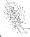
- Fig. 1 shows an embodiment of the underfloor wheelset inspection device 1 according to the present invention.
- a first wheelset 2 and a second wheelset 3 are disposed on a rail track 8.
- the wheelsets 2, 3 may belong to the same bogie (not shown) of a rail vehicle.
- the wheelsets 2, 3 are each comprised of a right wheel 21, 31 and a left wheel 22, 32.
- the right and left wheels 21, 22, 31, 32 are formed as disk-shaped objects.
- the right wheel 21, 31 and the left wheel 22, 32 of the same wheelset 2, 3 are connected to each other by a corresponding axle 23, 33 disposed in the center of these wheels 21, 22, 31, 32.
- the axles 23, 33 connect the corresponding right wheel 21, 31 to the corresponding left wheel 22, 32 such that they are parallel to each other.
- Each wheel 21, 22, 31, 32 comprises a running tread 211, 221, 311, 321 that is formed at the outer circumference of the wheel 21, 22, 31, 32.
- the running treads 211, 221, 311, 321 form the sections of the wheelsets 2, 3 contacting the rail track 8.
- the first wheelset 2 and the second wheelset 3 are disposed on the rail track 8 with a distance from each other in the direction perpendicular to the axles 23, 33.
- a first wheelset inspection unit 5 is located underneath the rail track 8 and the first wheelset 2.
- a second wheelset inspection unit 6 is located underneath the rail track 8 with a distance from the first wheelset inspection unit 5 along the rail direction such that the second wheelset inspection unit 6 is located underneath the second wheelset 3.
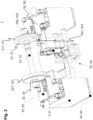
- each of the wheelset inspection units 5, 6 comprises two box-like shaped body parts that are connected by a frame structure, as shown in more detail in fig. 2 .
- the first body part is disposed underneath the left wheels 22, 32
- the frame structure is disposed underneath the axles 23, 33
- the second body part is disposed underneath the right wheels 21, 31.
- the first wheelset lifting units 51, 61 is located, and on the second body part the second wheelset lifting unit 52, 62 is located.
- the wheelset lifting units 51, 52, 61, 62 are formed by a left motor unit and a right motor unit which can be pivoted about an axis parallel to the axle 23, 33 of the wheelsets 2, 3.
- the motor units are positioned on a left and right side at the lower half of a wheel 21, 22 and contact running treads of the wheel 211, 221.
- the hydraulic lifting mechanism may comprise at least one hydraulic cylinder.
- the motor units are additionally designed so that they can rotate the section which contacts the running tread separately 211, 221, 311, 321 about an axis parallel to the axle 23, 33 of the wheel sets 2, 3. When these sections are set in rotation, rotation is transmitted to the wheels 21, 22, 31, 32.
- the left motor unit is set in rotation in one direction and the right motor unit is set in rotation in the opposite direction.
- the first wheelset inspection unit 5 and the second wheelset inspection unit 6 rotate the wheels 21, 22, 31, 32 belonging to a wheelset 2, 3 in such a way that they rotate simultaneously and that a rotation of the left wheels 22, 32 and the right wheels 21, 31 is generated in the same direction of rotation around the axle 23, 33.
- Each of the motor units may comprise a hydraulic motor for rotating the corresponding wheel 21, 22, 31, 32.
- a movement device 532, 632 is connected to the frame structure at a first end and carries a sensor 531, 631 at a second end.
- the movement device 532, 632 is formed as a robotic arm that comprises multiple joints which are motorized using electric motors. Through actuation of the motors, the sensor 531, 631 can be moved freely in the three-dimensional space around the fixed end of the robotic arm within the reach of the robotic arm. As shown in Fig. 1 , the robotic arm of the first wheelset inspection unit 5 moved the sensor 531 into a left sensing position. In Fig. 2 the sensor 531, 631 is shown close to a right sensing position.
- a trolley 54, 64 is formed below the box-like body parts of the wheelset inspection units 5, 6, a trolley 54, 64 is formed.
- Each of the wheelset inspection units 5, 6 is mounted on the corresponding trolley 54, 64.
- the trolley 54, 64 is a platform that is configured to glide along the ground by means of linear actuators and rails disposed on the underside of the platform. Further, sensors are disposed on the platform to track position changes of the platform.
- a control unit 4 is located close to the wheel inspection units 5, 6.
- the control unit 4 connects through a wired connection to the wheel lifting units 51, 52, 61, 62, the probe units 53, 63 and the trolleys 54, 64, wherein the control unit 4 is configured to control said components of the wheel inspection units 5, 6 simultaneously.
- Figure 1 further shows a reference unit 7 with a reference wheel 71 located between the first wheel inspection unit 5 and the second wheelset inspection unit 6.
- the reference wheel 71 is a wheel that is approximately of the dimensions of a wheel 21, 22, 31, 32 of the wheelsets 2, 3.
- the reference unit 7 is disposed between the wheelset inspection units 5, 6 such that the robotic arms may move the sensor 531, 631 into a reference position without the need to move wheelset inspection units 5, 6 itself relative to the reference unit 7 by means of the trolleys 54, 64.
- the railway vehicle is positioned above the underfloor wheelset inspection device 1 in such a way that the wheelsets 2, 3 of the railway vehicle are arranged as shown in Fig. 1 .
- the wheelset inspection units 5, 6 are moved into such a position by means of its trolleys 54, 64.
- the first wheel lifting unit 5 and the second wheel lifting unit 6 simultaneously lift the respective wheelsets 2, 3 off the rail track 8. This is performed by the first wheel lifting units 51, 61 and the second wheel lifting units 51, 62 pivoting the left motor unit and the right motor unit to abut the running tread 211, 221, 311, 321 of the wheel 21, 22, 31, 32.
- the left and right motor unit are then pivoted upwards, i.e. in a direction away from the rail track 8, in a coordinated fashion to elevate the wheel 21, 22, 31, 32 from the rail track 8.
- the lifting of the wheels 21, 22, 31, 32 of a wheelset 2, 3 is performed simultaneously such that the wheelsets do not exhibit a tilt to either site of the rail track 8 during lifting.
- the lifted wheels 21, 22, 31, 32 are rotated by the corresponding first and second wheel lifting units 51, 52, 61, 62.
- first and second wheel lifting units 51, 52, 61, 62 In order to increase the space available underneath the raised wheels 21, 22 31, 32, short rail sections underneath the raised wheels 21, 22, 31, 32 are now moved parallel to the track of the rail track by means of the pull-back mechanisms.
- the robotic arm of the probe unit 53 of the first wheelset inspection unit 5 moves the sensor 531 to the left sensing position in the proximity of the left wheel 22 of the first wheelset 2 as shown in fig. 1 .
- the tread of the wheel 21 is probed by the sensor 531 for at least a full rotation of the wheel 22.
- the robotic arm moves the sensor 531 to the reference position in proximity of the reference wheel 71 to probe the reference wheel.
- the robotic arm of the probe unit 63 of the second wheelset inspection unit 6 moves the sensor 631 to the reference position in proximity of the reference wheel 71 to probe the reference wheel 71.
- the sensor 631 is moved to the left sensing position in the proximity of the left wheel 32 of the second wheelset 3.
- the tread of the wheel 321 is probed by the sensor 631 for at least a full rotation of the wheel 32.
- the probe unit 53 of the first wheelset inspection unit 5 probes the wheel 22 at the left sensing position while the probe unit 63 of the second wheelset inspection unit 6 probes the reference wheel 71
- the probe unit 53 of the first wheelset inspection unit 5 probes the reference wheel 71 while the probe unit 63 of the second wheelset inspection unit 6 probes the wheel 32 the left sensing position.
- the probe unit 53 of the first wheelset inspection unit 5 is moved to its right sensing position to probe the running tread 211 of the right wheel 21 of the first wheelset 2, wherein the probe unit 63 of the second wheelset inspection unit 6 is moved to the reference position to probe the reference wheel 71.
- the probe unit 53 of the fist wheelset inspection unit 5 is moved to the reference wheel 71, wherein the probe unit 63 of the second wheelset inspection unit 6 is moved to the right sensing position to probe the running tread 311 of the right wheel 31 of the second wheelset 3.
- the inspection procedure is concluded by moving both sensors 531, 631 to the reference position, closing the short rail sections underneath the raised wheels 21, 22, 31, 32, and lowering the wheelsets 2, 3 back onto the rail track 8.
- the sequence of the inspection process described above is not limited to this exact order. In principle, it is possible to approach the reference position before and/or after a sensing position. It is also possible not to approach the reference position at all. Furthermore, it is irrelevant in which order the left sensing position and the right sensing position are approached.
Landscapes
- Engineering & Computer Science (AREA)
- Mechanical Engineering (AREA)
- Physics & Mathematics (AREA)
- General Physics & Mathematics (AREA)
- Investigating Or Analyzing Materials By The Use Of Ultrasonic Waves (AREA)
Priority Applications (1)
| Application Number | Priority Date | Filing Date | Title |
|---|---|---|---|
| EP24209934.9A EP4494970A3 (de) | 2023-02-14 | 2023-02-14 | Unterflurradsatzprüfvorrichtung |
Applications Claiming Priority (2)
| Application Number | Priority Date | Filing Date | Title |
|---|---|---|---|
| EP24209934.9A EP4494970A3 (de) | 2023-02-14 | 2023-02-14 | Unterflurradsatzprüfvorrichtung |
| EP23156502.9A EP4417959B1 (de) | 2023-02-14 | 2023-02-14 | Unterflurradsatzprüfvorrichtung und verfahren zum prüfen von schienenfahrzeugradsätzen unter verwendung der unterflurradsatzprüfvorrichtung |
Related Parent Applications (2)
| Application Number | Title | Priority Date | Filing Date |
|---|---|---|---|
| EP23156502.9A Division EP4417959B1 (de) | 2023-02-14 | 2023-02-14 | Unterflurradsatzprüfvorrichtung und verfahren zum prüfen von schienenfahrzeugradsätzen unter verwendung der unterflurradsatzprüfvorrichtung |
| EP23156502.9A Division-Into EP4417959B1 (de) | 2023-02-14 | 2023-02-14 | Unterflurradsatzprüfvorrichtung und verfahren zum prüfen von schienenfahrzeugradsätzen unter verwendung der unterflurradsatzprüfvorrichtung |
Publications (2)
| Publication Number | Publication Date |
|---|---|
| EP4494970A2 true EP4494970A2 (de) | 2025-01-22 |
| EP4494970A3 EP4494970A3 (de) | 2025-01-29 |
Family
ID=85238990
Family Applications (2)
| Application Number | Title | Priority Date | Filing Date |
|---|---|---|---|
| EP23156502.9A Active EP4417959B1 (de) | 2023-02-14 | 2023-02-14 | Unterflurradsatzprüfvorrichtung und verfahren zum prüfen von schienenfahrzeugradsätzen unter verwendung der unterflurradsatzprüfvorrichtung |
| EP24209934.9A Pending EP4494970A3 (de) | 2023-02-14 | 2023-02-14 | Unterflurradsatzprüfvorrichtung |
Family Applications Before (1)
| Application Number | Title | Priority Date | Filing Date |
|---|---|---|---|
| EP23156502.9A Active EP4417959B1 (de) | 2023-02-14 | 2023-02-14 | Unterflurradsatzprüfvorrichtung und verfahren zum prüfen von schienenfahrzeugradsätzen unter verwendung der unterflurradsatzprüfvorrichtung |
Country Status (1)
| Country | Link |
|---|---|
| EP (2) | EP4417959B1 (de) |
Citations (3)
| Publication number | Priority date | Publication date | Assignee | Title |
|---|---|---|---|---|
| CN103868991A (zh) | 2014-03-20 | 2014-06-18 | 北京新联铁科技股份有限公司 | 一种双机械手轨道车辆超声波双轮探伤机及其工作方法 |
| EP2631151B1 (de) | 2012-02-21 | 2017-02-01 | VÚKV a.s. | Testanlage für stationäre Tests von Schienenfahrzeugen und Verfahren zur Messung auf der Testanlage |
| US20190367057A1 (en) | 2018-06-05 | 2019-12-05 | The Boeing Company | In-motion High-speed Non-destructive Evaluation for Railcar Axles |
-
2023
- 2023-02-14 EP EP23156502.9A patent/EP4417959B1/de active Active
- 2023-02-14 EP EP24209934.9A patent/EP4494970A3/de active Pending
Patent Citations (3)
| Publication number | Priority date | Publication date | Assignee | Title |
|---|---|---|---|---|
| EP2631151B1 (de) | 2012-02-21 | 2017-02-01 | VÚKV a.s. | Testanlage für stationäre Tests von Schienenfahrzeugen und Verfahren zur Messung auf der Testanlage |
| CN103868991A (zh) | 2014-03-20 | 2014-06-18 | 北京新联铁科技股份有限公司 | 一种双机械手轨道车辆超声波双轮探伤机及其工作方法 |
| US20190367057A1 (en) | 2018-06-05 | 2019-12-05 | The Boeing Company | In-motion High-speed Non-destructive Evaluation for Railcar Axles |
Also Published As
| Publication number | Publication date |
|---|---|
| EP4417959A1 (de) | 2024-08-21 |
| EP4417959C0 (de) | 2025-05-07 |
| EP4417959B1 (de) | 2025-05-07 |
| EP4494970A3 (de) | 2025-01-29 |
Similar Documents
| Publication | Publication Date | Title |
|---|---|---|
| KR102105518B1 (ko) | 두 개의 매니퓰레이터를 구비하는 휠 림 및 스포크 결함 검출 시스템 | |
| KR101605629B1 (ko) | 철도 차량의 윤축자동검사장치 및 방법 | |
| CN100523802C (zh) | 飞机机体的检查方法及装置 | |
| CN110553858A (zh) | 一种基于机器视觉的轨旁列车底盘智能检测装置和系统 | |
| KR101001164B1 (ko) | 철도차량 윤축의 위상배열 초음파 탐상장치 | |
| KR20060009377A (ko) | 반응기 헤드 구성 요소들의 검사 방법 및 장치 | |
| BR102012015982B1 (pt) | acessório de teste ultrassônico para uma roda | |
| CN106394604A (zh) | 一种适用于轨道列车轮对检测的自动化探伤设备 | |
| JP2002303611A (ja) | トンネル覆工コンクリートの非破壊検査方法及び装置 | |
| EP4494970A2 (de) | Unterflurradsatzprüfvorrichtung | |
| US5363702A (en) | Device for inspecting the rim of a railway wheel | |
| RU2289811C2 (ru) | Способ и устройство для неразрушающего тестирования или регистрации результатов измерений дискообразных или кольцеобразных объектов | |
| JP3017459B2 (ja) | 鉄道車両の車輪の片寄りを測定する装置 | |
| KR20150049398A (ko) | 차륜 비분리형 초음파 탐상장치 | |
| JP2001208530A (ja) | 計測機検査用計測マスタのセッティング装置 | |
| RU113365U1 (ru) | Устройство для неразрушающего контроля колесных пар | |
| KR102592635B1 (ko) | 철도차량의 차륜 및 하부장치 검사용 로봇 시스템 | |
| RU78927U1 (ru) | Установка для автоматического измерения геометрических параметров железнодорожных цельнокатаных колес в потоке производства | |
| WO2023149820A1 (ru) | Способ и устройство для дефектоскопического сканирования | |
| RU2782309C1 (ru) | Установка для дефектоскопического сканирования | |
| EP2435296B1 (de) | Inspektionsvorrichtung | |
| CN120084216B (zh) | 一种厂房地面裂缝测量装置 | |
| CN222179506U (zh) | 一种轨道道钉无损检测装置 | |
| RU2209865C1 (ru) | Мобильный контрольно-вычислительный комплекс для измерения параметров износа головки рельса | |
| CN111765860B (zh) | 一种轮轴轴端智能检测方法 |
Legal Events
| Date | Code | Title | Description |
|---|---|---|---|
| PUAI | Public reference made under article 153(3) epc to a published international application that has entered the european phase |
Free format text: ORIGINAL CODE: 0009012 |
|
| STAA | Information on the status of an ep patent application or granted ep patent |
Free format text: STATUS: THE APPLICATION HAS BEEN PUBLISHED |
|
| REG | Reference to a national code |
Ref country code: DE Ref legal event code: R079 Free format text: PREVIOUS MAIN CLASS: B61K0009120000 Ipc: G01M0017100000 |
|
| PUAL | Search report despatched |
Free format text: ORIGINAL CODE: 0009013 |
|
| AC | Divisional application: reference to earlier application |
Ref document number: 4417959 Country of ref document: EP Kind code of ref document: P |
|
| AK | Designated contracting states |
Kind code of ref document: A2 Designated state(s): AL AT BE BG CH CY CZ DE DK EE ES FI FR GB GR HR HU IE IS IT LI LT LU LV MC ME MK MT NL NO PL PT RO RS SE SI SK SM TR |
|
| AK | Designated contracting states |
Kind code of ref document: A3 Designated state(s): AL AT BE BG CH CY CZ DE DK EE ES FI FR GB GR HR HU IE IS IT LI LT LU LV MC ME MK MT NL NO PL PT RO RS SE SI SK SM TR |
|
| RIC1 | Information provided on ipc code assigned before grant |
Ipc: B61K 9/12 20060101ALI20241224BHEP Ipc: G01M 17/10 20060101AFI20241224BHEP |
|
| STAA | Information on the status of an ep patent application or granted ep patent |
Free format text: STATUS: REQUEST FOR EXAMINATION WAS MADE |
|
| 17P | Request for examination filed |
Effective date: 20250728 |