EP4494951A1 - Bremssystem für ein zugfahrzeug - Google Patents
Bremssystem für ein zugfahrzeug Download PDFInfo
- Publication number
- EP4494951A1 EP4494951A1 EP24189067.2A EP24189067A EP4494951A1 EP 4494951 A1 EP4494951 A1 EP 4494951A1 EP 24189067 A EP24189067 A EP 24189067A EP 4494951 A1 EP4494951 A1 EP 4494951A1
- Authority
- EP
- European Patent Office
- Prior art keywords
- valve
- brake
- trailer
- pressure medium
- pressure
- Prior art date
- Legal status (The legal status is an assumption and is not a legal conclusion. Google has not performed a legal analysis and makes no representation as to the accuracy of the status listed.)
- Pending
Links
Images

Classifications
-
- B—PERFORMING OPERATIONS; TRANSPORTING
- B60—VEHICLES IN GENERAL
- B60T—VEHICLE BRAKE CONTROL SYSTEMS OR PARTS THEREOF; BRAKE CONTROL SYSTEMS OR PARTS THEREOF, IN GENERAL; ARRANGEMENT OF BRAKING ELEMENTS ON VEHICLES IN GENERAL; PORTABLE DEVICES FOR PREVENTING UNWANTED MOVEMENT OF VEHICLES; VEHICLE MODIFICATIONS TO FACILITATE COOLING OF BRAKES
- B60T8/00—Arrangements for adjusting wheel-braking force to meet varying vehicular or ground-surface conditions, e.g. limiting or varying distribution of braking force
- B60T8/17—Using electrical or electronic regulation means to control braking
- B60T8/1701—Braking or traction control means specially adapted for particular types of vehicles
-
- B—PERFORMING OPERATIONS; TRANSPORTING
- B60—VEHICLES IN GENERAL
- B60Q—ARRANGEMENT OF SIGNALLING OR LIGHTING DEVICES, THE MOUNTING OR SUPPORTING THEREOF OR CIRCUITS THEREFOR, FOR VEHICLES IN GENERAL
- B60Q9/00—Arrangement or adaptation of signal devices not provided for in one of main groups B60Q1/00 - B60Q7/00, e.g. haptic signalling
-
- B—PERFORMING OPERATIONS; TRANSPORTING
- B60—VEHICLES IN GENERAL
- B60T—VEHICLE BRAKE CONTROL SYSTEMS OR PARTS THEREOF; BRAKE CONTROL SYSTEMS OR PARTS THEREOF, IN GENERAL; ARRANGEMENT OF BRAKING ELEMENTS ON VEHICLES IN GENERAL; PORTABLE DEVICES FOR PREVENTING UNWANTED MOVEMENT OF VEHICLES; VEHICLE MODIFICATIONS TO FACILITATE COOLING OF BRAKES
- B60T13/00—Transmitting braking action from initiating means to ultimate brake actuator with power assistance or drive; Brake systems incorporating such transmitting means, e.g. air-pressure brake systems
- B60T13/10—Transmitting braking action from initiating means to ultimate brake actuator with power assistance or drive; Brake systems incorporating such transmitting means, e.g. air-pressure brake systems with fluid assistance, drive, or release
- B60T13/24—Transmitting braking action from initiating means to ultimate brake actuator with power assistance or drive; Brake systems incorporating such transmitting means, e.g. air-pressure brake systems with fluid assistance, drive, or release the fluid being gaseous
- B60T13/26—Compressed-air systems
- B60T13/261—Compressed-air systems systems with both indirect application and application by springs or weights and released by compressed air
- B60T13/263—Compressed-air systems systems with both indirect application and application by springs or weights and released by compressed air specially adapted for coupling with dependent systems, e.g. tractor-trailer systems
-
- B—PERFORMING OPERATIONS; TRANSPORTING
- B60—VEHICLES IN GENERAL
- B60T—VEHICLE BRAKE CONTROL SYSTEMS OR PARTS THEREOF; BRAKE CONTROL SYSTEMS OR PARTS THEREOF, IN GENERAL; ARRANGEMENT OF BRAKING ELEMENTS ON VEHICLES IN GENERAL; PORTABLE DEVICES FOR PREVENTING UNWANTED MOVEMENT OF VEHICLES; VEHICLE MODIFICATIONS TO FACILITATE COOLING OF BRAKES
- B60T13/00—Transmitting braking action from initiating means to ultimate brake actuator with power assistance or drive; Brake systems incorporating such transmitting means, e.g. air-pressure brake systems
- B60T13/10—Transmitting braking action from initiating means to ultimate brake actuator with power assistance or drive; Brake systems incorporating such transmitting means, e.g. air-pressure brake systems with fluid assistance, drive, or release
- B60T13/24—Transmitting braking action from initiating means to ultimate brake actuator with power assistance or drive; Brake systems incorporating such transmitting means, e.g. air-pressure brake systems with fluid assistance, drive, or release the fluid being gaseous
- B60T13/26—Compressed-air systems
- B60T13/38—Brakes applied by springs or weights and released by compressed air
- B60T13/385—Control arrangements therefor
-
- B—PERFORMING OPERATIONS; TRANSPORTING
- B60—VEHICLES IN GENERAL
- B60T—VEHICLE BRAKE CONTROL SYSTEMS OR PARTS THEREOF; BRAKE CONTROL SYSTEMS OR PARTS THEREOF, IN GENERAL; ARRANGEMENT OF BRAKING ELEMENTS ON VEHICLES IN GENERAL; PORTABLE DEVICES FOR PREVENTING UNWANTED MOVEMENT OF VEHICLES; VEHICLE MODIFICATIONS TO FACILITATE COOLING OF BRAKES
- B60T13/00—Transmitting braking action from initiating means to ultimate brake actuator with power assistance or drive; Brake systems incorporating such transmitting means, e.g. air-pressure brake systems
- B60T13/10—Transmitting braking action from initiating means to ultimate brake actuator with power assistance or drive; Brake systems incorporating such transmitting means, e.g. air-pressure brake systems with fluid assistance, drive, or release
- B60T13/66—Electrical control in fluid-pressure brake systems
- B60T13/662—Electrical control in fluid-pressure brake systems characterised by specified functions of the control system components
-
- B—PERFORMING OPERATIONS; TRANSPORTING
- B60—VEHICLES IN GENERAL
- B60T—VEHICLE BRAKE CONTROL SYSTEMS OR PARTS THEREOF; BRAKE CONTROL SYSTEMS OR PARTS THEREOF, IN GENERAL; ARRANGEMENT OF BRAKING ELEMENTS ON VEHICLES IN GENERAL; PORTABLE DEVICES FOR PREVENTING UNWANTED MOVEMENT OF VEHICLES; VEHICLE MODIFICATIONS TO FACILITATE COOLING OF BRAKES
- B60T13/00—Transmitting braking action from initiating means to ultimate brake actuator with power assistance or drive; Brake systems incorporating such transmitting means, e.g. air-pressure brake systems
- B60T13/10—Transmitting braking action from initiating means to ultimate brake actuator with power assistance or drive; Brake systems incorporating such transmitting means, e.g. air-pressure brake systems with fluid assistance, drive, or release
- B60T13/66—Electrical control in fluid-pressure brake systems
- B60T13/68—Electrical control in fluid-pressure brake systems by electrically-controlled valves
- B60T13/683—Electrical control in fluid-pressure brake systems by electrically-controlled valves in pneumatic systems or parts thereof
-
- B—PERFORMING OPERATIONS; TRANSPORTING
- B60—VEHICLES IN GENERAL
- B60T—VEHICLE BRAKE CONTROL SYSTEMS OR PARTS THEREOF; BRAKE CONTROL SYSTEMS OR PARTS THEREOF, IN GENERAL; ARRANGEMENT OF BRAKING ELEMENTS ON VEHICLES IN GENERAL; PORTABLE DEVICES FOR PREVENTING UNWANTED MOVEMENT OF VEHICLES; VEHICLE MODIFICATIONS TO FACILITATE COOLING OF BRAKES
- B60T15/00—Construction arrangement, or operation of valves incorporated in power brake systems and not covered by groups B60T11/00 or B60T13/00
- B60T15/02—Application and release valves
- B60T15/025—Electrically controlled valves
- B60T15/027—Electrically controlled valves in pneumatic systems
-
- B—PERFORMING OPERATIONS; TRANSPORTING
- B60—VEHICLES IN GENERAL
- B60T—VEHICLE BRAKE CONTROL SYSTEMS OR PARTS THEREOF; BRAKE CONTROL SYSTEMS OR PARTS THEREOF, IN GENERAL; ARRANGEMENT OF BRAKING ELEMENTS ON VEHICLES IN GENERAL; PORTABLE DEVICES FOR PREVENTING UNWANTED MOVEMENT OF VEHICLES; VEHICLE MODIFICATIONS TO FACILITATE COOLING OF BRAKES
- B60T17/00—Component parts, details, or accessories of power brake systems not covered by groups B60T8/00, B60T13/00 or B60T15/00, or presenting other characteristic features
- B60T17/04—Arrangements of piping, valves in the piping, e.g. cut-off valves, couplings or air hoses
-
- B—PERFORMING OPERATIONS; TRANSPORTING
- B60—VEHICLES IN GENERAL
- B60T—VEHICLE BRAKE CONTROL SYSTEMS OR PARTS THEREOF; BRAKE CONTROL SYSTEMS OR PARTS THEREOF, IN GENERAL; ARRANGEMENT OF BRAKING ELEMENTS ON VEHICLES IN GENERAL; PORTABLE DEVICES FOR PREVENTING UNWANTED MOVEMENT OF VEHICLES; VEHICLE MODIFICATIONS TO FACILITATE COOLING OF BRAKES
- B60T17/00—Component parts, details, or accessories of power brake systems not covered by groups B60T8/00, B60T13/00 or B60T15/00, or presenting other characteristic features
- B60T17/18—Safety devices; Monitoring
- B60T17/22—Devices for monitoring or checking brake systems; Signal devices
-
- B—PERFORMING OPERATIONS; TRANSPORTING
- B60—VEHICLES IN GENERAL
- B60T—VEHICLE BRAKE CONTROL SYSTEMS OR PARTS THEREOF; BRAKE CONTROL SYSTEMS OR PARTS THEREOF, IN GENERAL; ARRANGEMENT OF BRAKING ELEMENTS ON VEHICLES IN GENERAL; PORTABLE DEVICES FOR PREVENTING UNWANTED MOVEMENT OF VEHICLES; VEHICLE MODIFICATIONS TO FACILITATE COOLING OF BRAKES
- B60T17/00—Component parts, details, or accessories of power brake systems not covered by groups B60T8/00, B60T13/00 or B60T15/00, or presenting other characteristic features
- B60T17/18—Safety devices; Monitoring
- B60T17/22—Devices for monitoring or checking brake systems; Signal devices
- B60T17/221—Procedure or apparatus for checking or keeping in a correct functioning condition of brake systems
-
- B—PERFORMING OPERATIONS; TRANSPORTING
- B60—VEHICLES IN GENERAL
- B60T—VEHICLE BRAKE CONTROL SYSTEMS OR PARTS THEREOF; BRAKE CONTROL SYSTEMS OR PARTS THEREOF, IN GENERAL; ARRANGEMENT OF BRAKING ELEMENTS ON VEHICLES IN GENERAL; PORTABLE DEVICES FOR PREVENTING UNWANTED MOVEMENT OF VEHICLES; VEHICLE MODIFICATIONS TO FACILITATE COOLING OF BRAKES
- B60T7/00—Brake-action initiating means
- B60T7/12—Brake-action initiating means for automatic initiation; for initiation not subject to will of driver or passenger
- B60T7/20—Brake-action initiating means for automatic initiation; for initiation not subject to will of driver or passenger specially for trailers, e.g. in case of uncoupling of or overrunning by trailer
-
- B—PERFORMING OPERATIONS; TRANSPORTING
- B60—VEHICLES IN GENERAL
- B60T—VEHICLE BRAKE CONTROL SYSTEMS OR PARTS THEREOF; BRAKE CONTROL SYSTEMS OR PARTS THEREOF, IN GENERAL; ARRANGEMENT OF BRAKING ELEMENTS ON VEHICLES IN GENERAL; PORTABLE DEVICES FOR PREVENTING UNWANTED MOVEMENT OF VEHICLES; VEHICLE MODIFICATIONS TO FACILITATE COOLING OF BRAKES
- B60T2270/00—Further aspects of brake control systems not otherwise provided for
- B60T2270/40—Failsafe aspects of brake control systems
-
- B—PERFORMING OPERATIONS; TRANSPORTING
- B60—VEHICLES IN GENERAL
- B60T—VEHICLE BRAKE CONTROL SYSTEMS OR PARTS THEREOF; BRAKE CONTROL SYSTEMS OR PARTS THEREOF, IN GENERAL; ARRANGEMENT OF BRAKING ELEMENTS ON VEHICLES IN GENERAL; PORTABLE DEVICES FOR PREVENTING UNWANTED MOVEMENT OF VEHICLES; VEHICLE MODIFICATIONS TO FACILITATE COOLING OF BRAKES
- B60T2270/00—Further aspects of brake control systems not otherwise provided for
- B60T2270/40—Failsafe aspects of brake control systems
- B60T2270/402—Back-up
-
- B—PERFORMING OPERATIONS; TRANSPORTING
- B60—VEHICLES IN GENERAL
- B60T—VEHICLE BRAKE CONTROL SYSTEMS OR PARTS THEREOF; BRAKE CONTROL SYSTEMS OR PARTS THEREOF, IN GENERAL; ARRANGEMENT OF BRAKING ELEMENTS ON VEHICLES IN GENERAL; PORTABLE DEVICES FOR PREVENTING UNWANTED MOVEMENT OF VEHICLES; VEHICLE MODIFICATIONS TO FACILITATE COOLING OF BRAKES
- B60T2270/00—Further aspects of brake control systems not otherwise provided for
- B60T2270/40—Failsafe aspects of brake control systems
- B60T2270/404—Brake-by-wire or X-by-wire failsafe
-
- B—PERFORMING OPERATIONS; TRANSPORTING
- B60—VEHICLES IN GENERAL
- B60T—VEHICLE BRAKE CONTROL SYSTEMS OR PARTS THEREOF; BRAKE CONTROL SYSTEMS OR PARTS THEREOF, IN GENERAL; ARRANGEMENT OF BRAKING ELEMENTS ON VEHICLES IN GENERAL; PORTABLE DEVICES FOR PREVENTING UNWANTED MOVEMENT OF VEHICLES; VEHICLE MODIFICATIONS TO FACILITATE COOLING OF BRAKES
- B60T2270/00—Further aspects of brake control systems not otherwise provided for
- B60T2270/40—Failsafe aspects of brake control systems
- B60T2270/413—Plausibility monitoring, cross check, redundancy
-
- F—MECHANICAL ENGINEERING; LIGHTING; HEATING; WEAPONS; BLASTING
- F16—ENGINEERING ELEMENTS AND UNITS; GENERAL MEASURES FOR PRODUCING AND MAINTAINING EFFECTIVE FUNCTIONING OF MACHINES OR INSTALLATIONS; THERMAL INSULATION IN GENERAL
- F16D—COUPLINGS FOR TRANSMITTING ROTATION; CLUTCHES; BRAKES
- F16D2121/00—Type of actuator operation force
- F16D2121/02—Fluid pressure
- F16D2121/12—Fluid pressure for releasing a normally applied brake, the type of actuator being irrelevant or not provided for in groups F16D2121/04 - F16D2121/10
-
- F—MECHANICAL ENGINEERING; LIGHTING; HEATING; WEAPONS; BLASTING
- F16—ENGINEERING ELEMENTS AND UNITS; GENERAL MEASURES FOR PRODUCING AND MAINTAINING EFFECTIVE FUNCTIONING OF MACHINES OR INSTALLATIONS; THERMAL INSULATION IN GENERAL
- F16D—COUPLINGS FOR TRANSMITTING ROTATION; CLUTCHES; BRAKES
- F16D2121/00—Type of actuator operation force
- F16D2121/14—Mechanical
Definitions
- the invention relates to a braking system for a towing vehicle.
- a further claim is directed to a method for controlling the braking system.
- a powered vehicle is known with a spring-applied, hydraulically releasing (SAHR) vehicle brake comprising first and second braking elements engageable with one another, the first of which forms part of or is attached to a rotatable element of the vehicle's drive train and the second of which is non-rotatably and movably attached to the vehicle such that the first and second elements are engageable and disengageable with one another.
- SAHR hydraulically releasing
- the SAHR vehicle brake comprising (i) an elastically deformable element acting on the second braking element to force the first and second braking elements into mutual engagement, and (ii) a hydraulic control circuit for applying hydraulic pressure to the second braking element to counteract the action of the elastically deformable element and thereby maintain the first and second braking elements normally separated from one another, the vehicle comprising a hydraulic relief valve adjustable between a one-way valve configuration allowing pressure to be applied to the second braking element and preventing pressure relief therefrom, and a pressure reducing configuration providing bidirectional flow of hydraulic fluid by means of the hydraulic relief valve.
- the hydraulic relief valve comprises a biasing element and is characterized in that the hydraulic relief valve is part of a non-electrical fail-safe device of the vehicle, in which the one-way valve configuration is effective when a driving mode of the vehicle is selected and the biasing element biases the hydraulic relief valve into the one-way valve configuration.
- One object of the present invention is to provide a braking system with low hardware and software complexity. In the event of an inadvertently jammed valve, the braking system should ensure that a parking lock can be activated.
- the object is achieved by the subject matter of the independent patent claims.
- Advantageous embodiments are the subject matter of the subclaims, the following description and the figures.
- the present invention is fundamentally based on the idea of reducing the pressure in the circuit of the parking brake system.
- a direct connection between the reservoir or the pressure medium source, the parking brake system and the trailer control system is provided for a parking brake system.
- the present invention proposes using the trailer control valve.
- a brake valve for controlling the parking brake of the towing vehicle can also be cyclically activated in order to reduce the pressure in the supply line of the parking brake system. As a result, the pressure in the brake cylinders reaches a lower limit so that the spring brake cylinders used can actuate the parking brake system.
- a braking system for a towing vehicle comprises a pressure medium source for storing pressurized pressure medium.
- the pressure medium source e.g. a tank or an accumulator
- the pressure medium source is designed to output the stored pressure medium in order to actuate brake cylinders of the towing vehicle and/or a trailer vehicle towed by the towing vehicle.
- a drive motor of the towing vehicle can fill the pressure medium source, e.g. by driving a compressor that sucks in air, compresses it and supplies it to the pressure medium source.
- the pressure medium can be a pneumatic pressure medium (e.g.
- the braking system can therefore also be a pneumatic or a hydraulic braking system.
- the braking system also comprises a parking brake module with a control valve and - optionally - with a redundancy valve.
- the braking system comprises a trailer control valve system for a trailer brake of a trailer vehicle, which is pulled by the towing vehicle, and an electronic control unit.
- the invention is described with reference to the embodiment with a control valve and the optional redundancy valve. However, the statements also apply analogously to an embodiment which only has the control valve and no redundancy valve.
- the control valve and the redundancy valve are mechanically preloaded in a closed state.
- the electronic control unit is designed to control the control valve and the redundancy valve in such a way that they move into an open state against the mechanical preload.
- pressure medium from the pressure medium source is directed into at least one brake cylinder of the towing vehicle in order to build up a deactivation pressure in the brake cylinder so that a parking lock of the towing vehicle is deactivated.
- the invention provides that pressure medium is released via the trailer control valve system into a pressure-free environment so that the pressure medium source is emptied in such a way that the pressure medium contained therein is no longer sufficient to deactivate the parking brake.
- the electronic control unit is set up to control the trailer control valve system in such a way that pressure medium escapes via the trailer control valve system into a pressure-free environment, whereby the pressure medium source is emptied if the control valve or the redundancy valve remains in the open state due to a mechanical defect although it should be in the closed state and if the ignition of the towing vehicle and thus also a compressor for filling the pressure medium source are switched off.
- the electronic control unit can be designed to control the trailer control valve system in such a way that control that a brake pressure output for a trailer control line, which supplies the trailer brake with pressure medium, is intermittently pressurized.
- the trailer control line can be connected to the brake pressure output and to the trailer brake, wherein the electronic control unit is designed to control the trailer control valve system such that the trailer brake is alternately activated and deactivated in order to empty the pressure medium source via the trailer control valve system (16). If the brake pressure output for the trailer control line is pressurized, then the trailer brake is activated so that at least one wheel of the trailer is locked. If the brake pressure output for the trailer control line is not pressurized (i.e. during one of the interruptions in the pressurization of the brake pressure output), then the trailer brake is deactivated so that at least one wheel of the trailer is not locked.
- the trailer control valve system can comprise an inlet valve, an outlet valve and a trailer relay valve, wherein the pressure medium source is connected to the inlet valve and to the trailer relay valve.
- the inlet valve can be mechanically preloaded in a closed state.
- the inlet valve can also be designed as an electromagnetically controlled proportional directional control valve. However, this is purely exemplary and not mandatory.
- the inlet valve can also be designed as a simple directional control valve, for example, which can be placed in the closed state and in an open state.
- the outlet valve can be mechanically preloaded in an open state.
- the outlet valve can also be designed as an electromagnetically controlled proportional directional control valve. However, this is also purely exemplary and not mandatory.
- the outlet valve can also be designed as a simple directional control valve, for example, which can be placed in the open state and in a closed state.
- the electronic control unit is in particular designed to control the inlet valve and the outlet valve in such a way that, in order to activate the trailer brake, the inlet valve is placed in an open state and the outlet valve is simultaneously placed in a closed state, whereby the inlet valve outputs pressure medium under a control pressure to the trailer vehicle relay valve, which is based on the control pressure below a brake control pressure releases pressure medium into the trailer control line to activate the trailer brake.
- the inlet valve and the outlet valve can both be biased in the closed state or in the open state.
- the electronic control unit for deactivating the trailer brake is designed to put the inlet valve into the closed state and the outlet valve into the open state, whereby the inlet valve does not output any control pressure to the trailer vehicle relay valve and pressure medium escapes from the trailer control line via the trailer vehicle relay valve into the pressure-free environment (U).
- the electronic control unit is in particular designed to cyclically repeat the activation and deactivation of the trailer brake in order to empty the pressure medium source.
- the advantage of this solution is the large amount of air that is required to fill the trailer control line and which is then sucked out again.
- a certain compressed air volume of the compressed air reservoir is used, which depends on the trailer. By filling it while the air supply is stopped (compressor switched off), the pressure in the compressed air reservoir drops. When opened, the air from the trailer control line can be released into the unpressurized environment via a connection of the trailer control valve system.
- the electronic control unit is designed to control the inlet valve and the outlet valve in such a way that the inlet valve and the outlet valve are set to the open state so that pressure medium continuously escapes from the pressure medium source via the inlet valve and via the outlet valve into the unpressurized environment.
- the inlet and outlet valves are thus switched over in such a way that both valves are in the open position. This leads to a constant air leakage from the inlet to the outlet of the trailer control valve system.
- the advantage of such a solution is a constant, continuous pressure reduction.
- the pressure medium source can be emptied via the trailer control valve system without a parallel activation and deactivation of the parking brake of the towing vehicle.
- the brake valve for the parking brake of the towing vehicle is actuated once in order to completely release the pressure from the spring chamber or the brake cylinder of the parking brake of the towing vehicle. This measure is necessary if the parking brake system is protected by a check valve which protects the spring chamber against pressure losses in the storage tank due to leaks in the trailer control system.
- the brake system comprises a check valve which is arranged between the pressure medium source on the one hand and the brake cylinder on the other hand and prevents a flow of pressure medium from the brake cylinder in the direction of the pressure medium source.
- the electronic control unit is designed to control the brake valve in such a way that it goes into a closed state after the pressure medium source has been sufficiently emptied.
- the feature "sufficiently drained” can be understood in particular to mean that the pressure medium still stored in the pressure medium source is not sufficient to deactivate the parking brake(s) and the trailer brake. As a result, pressure medium escapes from the brake cylinder via the brake valve directly into the pressure-free environment until the brake cylinder has been drained to such an extent that the parking brake is activated.
- the electronic control unit can be set up to control the brake valve in such a way that it alternates between a closed state and an open state if the control valve or the redundancy valve remains in the open state due to a mechanical defect, although it should be in the closed state, and if the ignition of the towing vehicle and thus also the compressor for filling the pressure medium source are switched off. If the brake valve is in the closed state, pressure medium escapes from the brake cylinder via the brake valve directly into the pressure-free environment. Furthermore, no pressure medium is released from the pressure medium source into the brake cylinder. If, however, the brake valve is in the open state, then pressure medium is fed from the pressure medium source into the brake cylinder.
- the quick-vent valve is designed to release pressure medium from the brake cylinder and/or the trailer control line directly into the pressure-free environment.
- the quick-vent valve is preferably of the single-line type.
- the quick-vent valve is arranged in at least one of the following positions, namely between a relay valve and a brake cylinder of the parking lock of the towing vehicle, within the said relay valve, within the brake cylinder and downstream of the trailer control valve system, in particular in the trailer control line that is connected to the trailer control valve system. Since quick exhaust valves offer large air passages and the possibility of placing these valves close to the pressurized volumes (brake cylinder, trailer control valve), rapid exhaust is possible without being limited by small flow diameters of other valves or long lines in between.
- the control valve and the redundancy valve are in the open state and output a control pressure which is applied to the trailer relay valve.
- the control pressure is applied to an inverted input of the trailer relay valve, so that no pressure is output in the direction of the trailer control line via the trailer vehicle relay valve when the control pressure is applied to the inverted input of the trailer vehicle relay valve.
- control valve and the redundancy valve output pressure medium to the trailer vehicle relay valve when the control valve and the redundancy valve are in the open state, so that the trailer vehicle relay valve does not output pressure medium into the trailer control line and the trailer brake is not activated.
- a warning/information of the driver can be provided.
- the driver requests activation of the parking brake via an interface. Since one of the parking brake valves is stuck in the open position, the spring brake cylinders are still under pressure and are not activated, so the parking brake is not applied. At least one pressure sensor located near the spring brake cylinders detects that the pressure is not being released.
- the electronic control unit of the brake now sends a warning to the motor vehicle, which could display a warning for the driver and instructions on how to bring the vehicle into a safe state.
- the driver should now bring the motor vehicle to a stop with the service or secondary braking system activated.
- the driver is requested to switch off the engine to avoid a continuous supply of air to the supply circuit of the parking brake system.
- the electronic control unit of the braking system detects that the engine is switched off via a certain terminal, the automated emptying of the pressure medium source can begin.
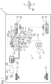
- Fig. 1 shows part of a braking system 1 for a towing vehicle 2, not shown in detail.
- the towing vehicle 2 is, for example, an agricultural utility vehicle, in particular a tractor.
- the braking system 1 in particular fulfils a parking or continuous braking function ("parking brake function") of wheels 13 of the towing vehicle 2 and of a Fig. 1 merely indicated trailer brake 3 of a trailer vehicle 4.
- parking brake function a parking or continuous braking function
- the functions described in more detail below can be part of a tractor braking system platform which ensures the safe operation of the braking system 1 in various failure scenarios.
- the braking system 1 comprises an electronically controllable parking brake module 5.
- the parking brake module 5 comprises a first 3/2-way valve designed as a control valve 6, a second 3/2-way valve designed as a redundancy valve 7, a pressure-controlled shuttle valve 8, a 3/2-way valve designed as a brake valve 10, a relay valve 11 (tractor vehicle relay valve), a check valve 12 and a pressure sensor 15.
- the control valve 6 and the redundancy valve 7 of the parking brake module 5 are supplied with pressure medium on the input side via a supply line 14 and via the check valve 12 from a pressure medium source 9, in the embodiment shown with pneumatic pressure medium in the form of compressed air.
- the relay valve 11 of the parking brake module 5 is also supplied with compressed air on the input side via the supply line 14 and the check valve 12 from the pressure medium source 9.
- the pressure medium source 9 can comprise a compressor 9.1, which can be driven by a drive machine or a motor (not shown) (e.g. an internal combustion engine or an electric motor) of the towing vehicle 2 when an ignition of the towing vehicle 2 is switched on.
- the control valve 6 and the redundancy valve 7 are connected in a pneumatic parallel circuit on the input side to the pressure medium source 9 via the supply line 14 and the check valve 12.
- the feature "connected” is to be understood in particular that the elements connected to one another are pneumatically connected to one another, i.e. that compressed air can flow from one element to the other element and vice versa if necessary.
- the shuttle valve 8 is connected on the input side to an output of the control valve 6 and the redundancy valve 7. On the output side, the shuttle valve 8 is connected to an input of the brake valve 10 and via a connecting line 17 to a first input 18 of a trailer control valve system 16 described in more detail below. The higher pressure of the two valves 6, 7 can thus be output via the output of the shuttle valve 8 in the direction of the brake valve 10 and the first input 18 of the trailer control valve system 16.
- a control pressure input 19 of the relay valve 11 is connected to an output of the brake valve 10.
- a supply pressure input 20 of the relay valve 11 is connected to the pressure medium source 9 via the check valve 12 and the supply line 14.
- a pressure output 21 of the relay valve 11 is connected via a brake cylinder line 22 to two brake cylinders 23 for actuating a parking brake 24 each.
- the pressure sensor 15 is arranged in the brake cylinder line 22 and measures the pressure prevailing therein, which can also be considered representative of a pressure within the brake cylinders 23. The pressure sensor 15 transmits the measured pressure to an electronic control unit 25 of the brake system 1.
- control valve 6 and the redundancy valve 7 are identical parts, but this is not mandatory.
- a valve slide of the control valve 6 and the redundancy valve 7 is each in a non-
- the valve housing shown is preloaded by a spring element in a closed switching position ("normally closed"), which is Fig. 1 shown closed state of the control valve 6 and the redundancy valve 7. If the control valve 6 and the redundancy valve 7 are in the closed state, then no compressed air is passed from the pressure medium source 9 via the control valve 6 and the redundancy valve 7 in the direction of the shuttle valve 8, the brake valve 10 arranged further downstream and the relay valve 11 arranged further downstream.
- the control valve 6 and the redundancy valve 7 have electromagnets that can be energized so that the valve spools are moved from the closed switching position to an open switching position, which corresponds to an open state of the control valve 6 and the redundancy valve 7.
- the electromagnets are energized by the electronic control unit 25.
- compressed air from the pressure medium source 9 is passed via the control valve 6 and the redundancy valve 7 and can be fed to the control pressure inlet 19 of the relay valve 11 via the shuttle valve 8 and the brake valve 10 arranged further downstream. If the control valve 6 fails, the pressure of the redundancy valve 7 can continue to be used, provided the redundancy valve 7 has not failed. If the redundancy valve 7 fails, the pressure of the control valve 6 can still be used, provided that the control valve 6 has not failed.
- a valve slide of the brake valve 10 is held within its valve housing by a spring element in a Fig. 1 shown open switching position ("normally open"), which corresponds to an open state of the brake valve 10.
- compressed air which comes from the pressure medium source 9 via the open control valve 6 or the opened redundancy valve 7 and the shuttle valve 8, via the brake valve 10 to the control pressure input 19 of the relay valve 11.
- the relay valve 11 feeds compressed air, which is present at the supply pressure input 20, into the brake cylinder line 22 via the pressure output 21. Consequently, the brake cylinders 23 are filled with compressed air, whereby a deactivation pressure is built up in the brake cylinders 23, so that the parking locks 24 are deactivated.
- the wheels 13 of the towing vehicle 2 are then not locked.
- the electronic control unit 25 can control the energization of an electromagnet of the brake valve 10 in such a way that the valve slide of the brake valve 10 is moved from the open switching position to a closed switching position, which corresponds to a closed state of the brake valve 10.
- compressed air can escape from the brake cylinders 23 via the relay valve 11 and the brake valve 10 into a pressureless environment U, so that the deactivation pressure is reduced and the parking lock 24 is activated.
- the wheels 13 of the towing vehicle 2 are then locked.
- the valve arrangement 5 has an inverting switching characteristic.
- the parking locks 24 of the towing vehicle 2 are actuated when no pressure is output via the relay valve 11 and are released when a sufficiently high pressure is output via the relay valve 11, which leads to the deactivation pressure within the brake cylinders 23.
- Fig. 1 shows that the electronic control unit 25 of the braking system 1 can be connected to an electronic (main) control unit 27 of the towing vehicle 2 via a CAN BUS 26.
- the electronic (main) control unit 27 of the towing vehicle 2 is connected in the embodiment shown in particular to a human-machine interface HMI in a driver's cabin of the towing vehicle 2.
- a driver or user of the towing vehicle 2 can operate the brake cylinders 23 of the towing vehicle 2 and/or the trailer brake 3 of the trailer vehicle 4. If the parking locks 24 are to be operated or activated in normal operation, ie when the electronic Control unit 25 is in an active state, then the control valve 6 and the redundancy valve 7 are deactivated, i.e.
- the control valve 6 and/or the redundancy valve 7 have a mechanical defect, which leads to a jammed opening position of the valve 6 and/or 7 in question.
- the pressure within the brake cylinders 23 cannot be released via the jammed valve 6 and/or 7 when the parking locks 24 are requested to be actuated.
- this pressure within the brake cylinders 23 can be reduced by opening the brake valve 10, overcoming the constant supply from the defective valve 6 and/or 7.
- the electronic control unit 25 will energize the electromagnet of the brake valve 10 in such a way that its valve slide is moved to the closed position.
- the brake cylinder 23 is connected to the pressure-free environment U via the relay valve 11 and the brake valve 10, whereas the control valve 6 and the redundancy valve 7 are separated from the relay valve 11 and the brake cylinders 23.
- compressed air escapes from the brake cylinder 23 via the brake valve 10 directly into the pressure-free environment U.
- no compressed air is fed from the pressure medium source 9 via the relay valve 11 into the brake cylinders 23.
- the electromagnet of the brake valve 10 would normally no longer be energized.
- the brake valve 10 would go into the pre-tensioned state, ie the valve slide of the brake valve 10 would be moved by its spring element into the position determined by Fig. 1 shown open switch position. This would move the brake cylinders 23 pressurized again and the parking locks 24 are released.
- the electronic control unit 25 (before it switches itself off or is allowed to be switched off) alternately sets the brake valve 10 to the open and closed state.
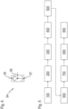
- Fig. 3 illustrates the scenario described above in terms of time courses of state values.
- a Fig. 3 The first graph 28 shown below shows the time course of the state of the control valve 6.
- Another in Fig. 3 The second graph 29 shown below shows the temporal progression of the state of the redundancy valve 7.
- a third graph 30 shows the temporal progression of the state of the brake valve 10.
- a fourth graph 31 shows the temporal progression of the relative pressure (0% corresponds to a pressure-free state, 100% to a maximum permissible pressure) that prevails within the brake cylinders 23.
- a limit value 32 for the pressure is also shown. If the pressure that prevails within the brake cylinders 23 is below the limit value 32, then the parking locks 24 are activated.
- the limit value 32 can, for example, be the deactivation pressure described above. Alternatively, a lower value can also be selected in order to increase security against unintended deactivation of the parking locks 24.
- a fifth graph 32 shows the temporal course of an output pressure of the pressure medium source 9.
- the towing vehicle 2 is stopped, e.g. by means of a service brake.
- the control valve 6, the redundancy valve 7 and the brake valve 10 remain in their open state, so that a pressure that is above the limit value 32 continues to prevail within the brake cylinders 23, whereby the parking locks 24 remain deactivated.
- the activation of the parking locks 24 is initiated, e.g. by the driver operating the human-machine interface HMI accordingly.
- the redundancy valve 7 is moved from the open switching position to the closed switching position by its spring element.
- this does not work with the control valve 6 because a mechanical defect ensures that the spring element of the control valve 6 cannot move its valve slide into the closed position.
- the control valve 6 therefore remains in the open state.
- the brake valve 10 remains in its open state as intended.
- the pressure 31 within the brake cylinder 14 does not drop because the control valve 6 is still open, so that compressed air from the pressure medium source 9 continues to flow unintentionally into the brake cylinder 14 via the relay valve 11.
- the electronic control unit 25 detects that the control valve 6 is in the open state, although it should be in the closed state to activate the parking locks 24.
- the electronic control unit 25 energizes the electromagnet of the brake valve 10 in such a way that its valve slide moves into the closed switching position.
- pressure medium escapes from the brake cylinders 23 via the relay valve 11 and the brake valve 10 into the pressure-free environment U.
- the pressure 31 within the pressure cylinders 14 falls below the limit value 32 and the parking locks 24 are activated.
- the ignition of the towing vehicle 2 is switched off, so that the pressure medium source 9 is no longer filled and can be emptied.
- the status of the ignition can be detected by the electronic control unit 25 by detecting a current that flows through a corresponding terminal ("TRM15") on the electronic control unit 27 of the towing vehicle 2 or not.
- the electronic control unit 25 of the brake system 1 now energizes the electromagnet of the brake valve 10 in such a way that its valve slide moves alternately into the open and closed switching position. This means that during an opening cycle 35 (in which the brake valve 10 is open) compressed air from the emptying pressure medium source 9 via the relay valve 11 into the brake cylinder 23, so that pressure builds up in the brake cylinder 23.
- the electronic control unit 25 As soon as the electronic control unit 25 detects that the limit value 32 is no longer reached during an opening cycle of the brake valve 10, it can switch itself off at a fifth time t 5 . Fig. 3 In the embodiment shown, the electronic control unit 25 waits for a further opening cycle before initiating its shutdown. When the electronic control unit 25 is switched off, it is in an inactive state, so that the brake valve 10 is placed in its mechanically preloaded open state. The redundancy valve 7 remains in its mechanically preloaded closed state. The control valve 6 continues to remain in its jammed open state.
- the braking system 1 has the pressure sensor 15.
- the pressure sensor 15 measures a line pressure within the brake cylinder line 22, which connects the relay valve 11 to the brake cylinders 14.
- the processor unit 25 accesses the line pressure measured by the pressure sensor 15 and can switch itself off as described above if the line pressure no longer reaches the predetermined limit value during the filling of the brake cylinders 23 (i.e. during one of the opening cycles 35 described above).
- the trailer control valve system 16 can also be used to empty the pressure medium source 9, both alternatively and in addition to the activation and deactivation of the parking lock 24 of the towing vehicle 2 described above.
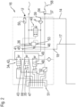
- the trailer control valve system 16 in particular an inlet valve 34, an outlet valve 35 and a trailer vehicle relay valve 36.
- a trailer control line 38 of the trailer vehicle 4 is connected on the one hand to a trailer brake connection or brake pressure output 37 of the trailer control valve system 5 and on the other hand to the trailer brake 3 of the trailer vehicle 4.
- the supply line 14 is connected to a second input 39 of the trailer control valve system 16.
- Compressed air from the pressure medium source 9 flows, on the one hand, bypassing the check valve 12 via the supply line 14 through the second inlet 39 into the trailer control valve system 16, where it is fed via a filter F and a cut-off valve 40 to a pressure inlet 41 of the trailer vehicle relay valve 36.
- compressed air from the pressure medium source 9 also flows, bypassing the check valve 12, via the supply line 14 through the second inlet 39 into the trailer control valve system 16, where it is fed via the filter F and bypassing the cut-off valve 40 to an inlet 42 of the inlet valve 34.
- An outlet 43 of the inlet valve 34 is connected, on the one hand, to an inlet 44 of the outlet valve 35.
- the output 43 of the inlet valve 34 is connected to a first control input 45 of the trailer relay valve 36.
- a second inverted control input 46 of the trailer relay valve 36 is connected to the first input 18 of the trailer control valve system 18.
- Compressed air output from the control valve 6 or the redundancy valve 7 can flow via the shuttle valve 8 and the connecting line 17 through the first input 18 into the trailer relay valve 36, where it is fed to the second inverted control input 46.
- An output 47 of the outlet valve 35 can also be connected to the unpressurized environment U via a redundancy valve 48 of the trailer control valve system 16, a drain line 49 and a silencer 50.
- the inlet valve 34 and the outlet valve 35 are electromagnetically controlled proportional directional control valves, each with an electromagnet that can be controlled by the electronic control unit 25 and a spring element for mechanically preloading a valve slide of the inlet valve 34 and the outlet valve 35.
- the inlet valve 34 is in one through Fig. 1 and 2
- the outlet valve 35 is mechanically preloaded in the closed state shown.
- Fig. 1 and 2 shown open state is mechanically prestressed. If the inlet valve 34 is in the closed state and the outlet valve 35 is in the open state, then no compressed air flows via the inlet valve 34 to the first control input 45 of the trailer relay valve 36.
- the trailer relay valve 36 If compressed air is additionally supplied to the second inverted control input 46 of the trailer relay valve 36, which is output by the control valve 6 or the redundancy valve 7, then the trailer relay valve 36 does not output any compressed air present at the pressure input 41 via its pressure output 53 in the direction of the brake pressure output 37. Accordingly, no compressed air flows into the trailer control line 38 and the trailer brake 3 is not activated, so that the wheels of the trailer 4 are not locked.
- the electronic control unit 25 is connected to a connector strip 51 of the trailer control valve system 16.
- the connector strip 51 is connected to the trailer control valve system 16 via electronic control lines 52 (for the sake of clarity, only one of these is shown in the Fig. 2 provided with a reference number) in particular with the electromagnets of the inlet valve 34 and the outlet valve 35.
- the electronic control unit 25 can thereby control the state of the inlet valve 34 and the outlet valve 35 via the connector strip 51 and the electronic control lines 52.
- the electronic control unit 25 can move the inlet valve 34 from the closed state to an open state by energizing its electromagnet against the mechanical prestress.
- the electronic control unit 25 can move the outlet valve 35 from the open state to a closed state by energizing its electromagnet against the mechanical prestress.
- the inlet valve 34 When the inlet valve 34 is in the open state and the outlet valve 35 is in the closed state, compressed air flows via the inlet valve 34 to the first control input 45 of the trailer vehicle relay valve 36.
- the inlet valve 34 outputs compressed air under a control pressure to the trailer vehicle relay valve 36, which, based on the control pressure, under a brake control pressure to the trailer brake connection 37. Compressed air flows accordingly into the trailer control line 38 and the trailer brake 3 is activated so that the wheels of the trailer vehicle 4 are locked.
- the electronic control unit 25 can then deactivate the trailer brake 3 by putting the inlet valve 34 back into the mechanically preloaded closed state by stopping the energization of its electromagnet.
- the electronic control unit 25 can put the outlet valve 35 back into the mechanically preloaded open state by stopping the energization of its electromagnet. This interrupts the pressurization of the brake pressure outlet 37 and the trailer control line 38, which supplies the trailer brake 3 with compressed air. On the other hand, compressed air in the trailer control line 38 is released into the unpressurized environment U via the trailer brake connection 37, the trailer vehicle relay valve 36 and the silencer 50.
- a volume of compressed air from the pressure medium source 9 is consumed, particularly when the control valve 6 and/or redundancy valve 7 is mechanically jammed in the open state, which contributes to emptying the pressure medium source 9.
- the compressor 9.1 of the pressure medium source 9 is no longer filled when the ignition and drive engine are switched off.
- the activation and deactivation of the trailer brake 3 can be repeated several times to contribute to emptying the pressure medium source 9, both as an alternative and in addition to the likewise repeated activation and deactivation of the parking brake 24 of the towing vehicle 2.
- the electronic control unit 25 can control the inlet valve 34 and the outlet valve 35 in such a way that both the inlet valve 34 and the outlet valve 35 are placed in the open state (alternative b)).
- compressed air continuously escapes from the pressure medium source 9 via the inlet valve 34, the outlet valve 35, the redundant valve 48, the drain line 49 and the silencer 50 into the unpressurized environment U.
- the check valve 12 is in accordance with Fig. 1 between the pressure medium source 9 on the one hand and the brake cylinder 23 on the other.
- the check valve 12 prevents compressed air from flowing from the brake cylinder 23 in the direction of the pressure medium source 9.
- the check valve 12 protects the spring chambers of the brake cylinders 23 against pressure losses in the reservoir 9 due to leaks in the trailer control system 16.
- the brake valve 10 is actuated once in order to completely release the pressure from the spring chambers of the brake cylinders 23.
- the electronic control unit 25 controls the brake valve 10 in such a way that it goes into the closed state after the pressure medium source 9 has been sufficiently emptied, whereby pressure medium escapes from the brake cylinder 23 via the brake valve 10 directly into the pressure-free environment U.
- the feature "after the pressure medium source 9 has been sufficiently emptied” can be understood in particular to mean that the compressed air still stored in the pressure medium source 9 is not sufficient to deactivate the parking brakes 24 and the trailer brake 3.
- At least one quick vent valve 54 is provided.
- the quick vent valve 54 can be integrated into the towing vehicle relay valve 11.
- the quick vent valve 54 can be arranged downstream of the trailer control valve system 16 or in the brake cylinder line 22 between the towing vehicle relay valve 11 and the brake cylinders 23.
- one of the quick vent valves 54 can be arranged in at least one of the brake cylinders 23 (not shown).
- the at least one quick vent valve 54 is in the through Fig.
- Embodiment of the single-line type resembles a check valve with a first port 55, a second port 56 and a third port 57.
- the vent of the quick exhaust valve 54 is closed as long as the first port 55 is under pressure. However, as soon as the first port 55 is depressurized, the pressure at the second port 56 opens the passage between the second port 55 and the third port 57 (outlet), so that the outlet of the quick exhaust valve 54 is vented.
- the first port 55 is connected to the brake pressure output 37.
- the second port 56 is connected to a coupling head 58 ("Yellow Coupling Head" YCH), which connects the brake pressure output 37 to the trailer control line 38.
- YCH Yellow Coupling Head
- the trailer control line 38 is connected to the quick vent valve 54.
- the third port 37 is connected to the unpressurized environment U. Consequently, the trailer control line 38 can be vented via the third port 57 of the quick vent valve 54, preferably via a noise or silencer. In a hydraulic alternative not shown, the venting could take place into a unpressurized tank.
- the first connection 55 is connected to the supply pressure inlet 20 of the towing vehicle relay valve 11.
- the second connection 56 is connected to a T-piece 59 between the two brake cylinders 23.
- the two brake cylinders 23 are thus connected to the quick vent valve 54.
- the third connection 37 is connected to the unpressurized environment U. Consequently, the brake cylinders can be vented via the third connection 57 of the quick vent valve 54, preferably via a noise damper or silencer. In a hydraulic alternative not shown, the venting could take place into a unpressurized tank.
- a special operation is present, namely the driver's request to apply the parking brake, which cannot be carried out due to the jammed valve 6 or 7.
- the brake cylinders 23 are therefore still pressurized, which is determined by the pressure sensor 15.
- the driver is informed of this special error and that the parking brake 24 is only applied when the ignition is switched off and thus the compressor 9.1 no longer supplies air to the pressure medium source 9 ("air tank 3").
- the electronic control unit 25 does not switch off in this special operation, but remains active.
- the electronic control unit 25 is now able to increase and decrease the pressure at the brake pressure outlet 37 by switching the inlet valve 34 and the outlet valve 35 of the trailer control valve system 16 and thus reduce the pressure in the pressure medium source 9.
- the brake valve 10 can be actuated once to reduce the pressure in the brake cylinders 23. However, switching off the brake valve 10 does not lead to a renewed release or deactivation of the parking brakes 24 due to the low supply pressure level.
- the electronic control of the trailer control valve system 16 is terminated. In this case, the pressure medium source 16 is emptied. Pressure can therefore no longer be output at the brake pressure outlet 37, nor at a trailer supply line 60.
- Trailers have a trailer brake valve which automatically goes into the braking position with the air supply stored on the trailer 4 when the trailer supply line 60 is depressurized ("red coupling head").
- Fig. 5 shows a sequence of a method for controlling the braking system according to Fig. 1 , which is provided in a first method step 100.
- the method ensures that the driver is warned/informed.
- the driver requests via the human-machine interface HMI indicates activation of the parking brakes 24. Since either the control valve 6 or the redundancy valve 7 is stuck in the open position, the spring brake cylinders 23 are still under pressure and are not activated, so that the parking brakes 24 are not applied.
- the electronic control unit 25 of the braking system 1 now sends a warning signal to the electronic (main) control unit 27 of the towing vehicle in a fourth method step 400.
- the warning signal can be visual (text and/or image display on a user interface such as a display, a red signal light, etc.) or acoustic, for example.
- the warning signal signals to the driver that the parking brakes 24 cannot be activated as intended.
- the warning signal may also contain instructions for the driver on how to bring the towing vehicle 2 and the trailer vehicle 4 into a safe condition in accordance with the procedural steps described below.
- a fifth method step 500 the driver will bring the towing vehicle 2 together with the trailer vehicle 4 to a stop with the service or secondary braking system activated.
- the driver is requested to switch off the engine of the towing vehicle 2 in order to avoid a continuous supply of air to the supply circuit of the parking brake module 5. Consequently, in a sixth method step 600, the driver will switch off the ignition of the towing vehicle 2 so that the compressor 9.1 for filling the pressure medium source 9 is switched off.
- the electronic control unit 25 of the braking system 1 detects that the engine has been switched off via the terminal TRM15, the electronic control unit 25 can begin to reduce the pressure in the pressure medium source 9 and thus also in the brake cylinders 23 and in the trailer braking system 3.
- a seventh method step 700 by releasing compressed air into the pressureless environment U via the trailer control valve system 16, in particular according to alternatives a) and b). Additionally or alternatively, the parking brakes 24 of the towing vehicle 1 can also be alternately activated and deactivated.
- an eighth method step 800 if the pressure medium source 9 is emptied to such an extent that the pressure medium still stored in the pressure medium source 9 is not sufficient to deactivate the parking brake 24, a safety signal is output which signals to the driver that the parking brakes 24 are now activated. The driver can then release the previously activated alternative braking system and leave the towing vehicle 2 in a ninth method step (900).
Landscapes
- Engineering & Computer Science (AREA)
- Mechanical Engineering (AREA)
- Transportation (AREA)
- Human Computer Interaction (AREA)
- Braking Systems And Boosters (AREA)
- Valves And Accessory Devices For Braking Systems (AREA)
Abstract
Die Erfindung betrifft ein Bremssystem (1) für ein Zugfahrzeug (2). Das Bremssystem (1) umfasst eine Druckmittelquelle (9) zur Bevorratung von unter Druck stehendem Druckmittel, ein Feststellbremsmodul (5) mit einem Steuerventil (6) und einem Redundanzventil (7), ein Anhängersteuerventilsystem (16) für eine Anhängerbremse (3) eines Anhängefahrzeugs (4), welches von dem Zugfahrzeug (2) gezogen wird, und eine elektronische Steuerungseinheit (25). Die elektronische Steuerungseinheit (25) ist insbesondere dazu eingerichtet, das Anhängersteuerventilsystem (16) derart zu steuern, dass Druckmittel über das Anhängersteuerventilsystem (16) in eine drucklose Umgebung (U) entweicht, wodurch die Druckmittelquelle (9) entleert wird, wenn das Steuerventil (6) oder das Redundanzventil (7) aufgrund eines mechanischen Defekts in einem geöffneten Zustand verharrt, obwohl es sich in einem geschlossenen Zustand befinden sollte, und wenn eine Zündung des Zugfahrzeugs (2) und damit auch ein Kompressor (9.1) zur Befüllung der Druckmittelquelle (9) ausgeschaltet sind.
Description
- Die Erfindung betrifft ein Bremssystem für ein Zugfahrzeug. Ein weiterer Anspruch ist auf ein Verfahren zur Steuerung des Bremssystems gerichtet.
- Aus der
EP 3 365 207 B1 ist ein angetriebenes Fahrzeug mit einer federbetätigten, hydraulisch öffnenden (SAHR) Fahrzeugbremse bekannt, die ein erstes und ein zweites Bremselement umfasst, die miteinander in Eingriff bringbar sind, wobei das Erste davon einen Teil eines drehbaren Elements des Antriebsstrangs des Fahrzeugs bildet oder an diesem befestigt ist und das Zweite davon drehfest und beweglich am Fahrzeug angebracht ist, sodass das erste und das zweite Element miteinander in Eingriff bringbar und voneinander trennbar sind. Dabei bewirkt ein gegenseitiger Eingriff der Bremselemente ein Bremsen der Drehung des drehbaren Elements, wobei die SAHR-Fahrzeugbremse (i) ein elastisch verformbares Element umfasst, das auf das zweite Bremselement wirkt, um das erste und das zweite Bremselement in gegenseitigen Eingriff zu zwingen, und (ii) einen hydraulischen Steuerkreis zum Aufbringen eines Hydraulikdrucks auf das zweite Bremselement umfasst, um der Wirkung des elastisch verformbaren Elements entgegenzuwirken und dadurch das erste und zweite Bremselement normalerweise getrennt voneinander zu halten, wobei das Fahrzeug ein hydraulisches Entlastungsventil umfasst, das zwischen einer Einweg-Ventilkonfiguration, die das Aufbringen von Druck auf das zweite Bremselement ermöglicht und eine Druckentlastung desselben verhindert, und einer Druckminderungskonfiguration verstellbar ist, die eine bidirektionale Strömung von Hydraulikfluid mittels des hydraulischen Entlastungsventils bereitstellt. Dabei umfasst das hydraulische Entlastungsventil ein Vorspannelement und ist dadurch gekennzeichnet, dass das hydraulische Entlastungsventil Teil einer nicht elektrischen Ausfallsicherung des Fahrzeug ist, in der die Einweg-Ventilkonfiguration wirksam ist, wenn ein Fahrmodus des Fahrzeugs gewählt ist und das Vorspannelement das hydraulische Entlastungsventil in die Einweg-Ventilkonfiguration vorspannt. - Eine Aufgabe der vorliegenden Erfindung kann darin gesehen werden, ein Bremssystem mit niedriger Hardware- und Software-Komplexität bereitzustellen. Dabei soll das Bremssystem bei einem unbeabsichtigt verklemmten Ventil sicherstellen, dass eine Parksperre aktiviert werden kann. Die Aufgabe wird gelöst durch die Gegenstände der unabhängigen Patentansprüche. Vorteilhafte Ausführungsformen sind Gegenstand der Unteransprüche, der folgenden Beschreibung sowie der Figuren.
- Grundsätzlich liegt der vorliegenden Erfindung liegt die Idee zugrunde, den Druck im Kreislauf der Feststellbremsanlage zu reduzieren. Insbesondere ist dabei für ein Feststellbremssystem eine direkte Verbindung zwischen dem Vorratsbehälter bzw. der Druckmittelquelle, dem Feststellbremssystem und dem Anhängersteuerungssystem vorgesehen. Um den Druckabbau des Vorratsbehälters zu unterstützen, schneller auf die Bremsanforderung des Fahrers zu reagieren und zusätzliche Komponenten im Innenraum des Zugfahrzeugs zu vermeiden, schlägt die vorliegende Erfindung vor, das Anhängersteuerventil zu nutzen. Zusätzlich oder alternativ kann auch ein Bremsventil zur Steuerung der Feststellbremse des Zugfahrzeugs zyklisch aktiviert werden, um den Druck in der Versorgungsleitung des Feststellbremssystems zu reduzieren. Dadurch erreicht der Druck in den Bremszylindern einen unteren Grenzwert, sodass die verwendeten Federbremszylinder die Feststellbremsanlage betätigen können.
- In diesem Sinne wird gemäß einem ersten Aspekt der Erfindung ein Bremssystem für ein Zugfahrzeug bereitgestellt. Das Bremssystem umfasst eine Druckmittelquelle zur Bevorratung von unter Druck stehendem Druckmittel. Die Druckmittelquelle (z.B. ein Tank oder ein Akkumulator) ist dazu eingerichtet, das bevorratete Druckmittel auszugeben, um Bremszylinder des Zugfahrzeugs und/oder eines von dem Zugfahrzeug gezogenen Anhängefahrzeugs zu betätigen. Wenn die Zündung des Zugfahrzeugs eingeschaltet ist, kann ein Antriebsmotor des Zugfahrzeugs eine Befüllung der Druckmittelquelle bewirken, z.B. indem ein Kompressor angetrieben wird, der Luft ansaugt, verdichtet und der Druckmittelquelle zuführt. Bei dem Druckmittel kann es sich um ein pneumatisches Druckmittel (z.B. Druckluft) oder um ein hydraulisches Druckmittel (z.B. Öl) handeln. Somit kann es sich bei dem Bremssystem ebenfalls um ein pneumatisches oder um ein hydraulisches Bremssystem handeln. Das Bremssystem umfasst weiterhin ein Feststellbremsmodul mit einem Steuerventil und - optional - mit einem Redundanzventil. Ferner umfasst das Bremssystem ein Anhängersteuerventilsystem für eine Anhängerbremse eines Anhängefahrzeugs, welches von dem Zugfahrzeug gezogen wird, und eine elektronische Steuerungseinheit. Im Folgenden wird die Erfindung bezüglich der Ausführungsform mit einem Steuerventil und dem optionalen Redundanzventil beschrieben. Die Ausführungen gelten sinngemäß jedoch auch für eine Ausführungsform, welche lediglich das Steuerventil und kein Redundanzventil aufweist.
- Das Steuerventil und das Redundanzventil sind in einem geschlossenen Zustand mechanisch vorgespannt. In einem Normalbetrieb ist die elektronische Steuerungseinheit dazu eingerichtet ist, das Steuerventil und das Redundanzventil derart zu steuern, dass sie sich entgegen der mechanischen Vorspannung in einen geöffneten Zustand begeben. Dadurch wird Druckmittel aus der Druckmittelquelle in wenigstens einen Bremszylinder des Zugfahrzeugs geleitet wird, um in dem Bremszylinder einen Deaktivierungsdruck aufzubauen, sodass eine Parksperre des Zugfahrzeugs deaktiviert wird.
- Wenn das Steuerventil oder das Redundanzventil in dem geöffneten Zustand verklemmt sind und die Parksperre eingelegt werden soll, dann wird dem Bremszylinder weiterhin Druckmittel zugeführt, sodass der Druck innerhalb des Bremszylinders nicht abgebaut und die Parksperre nicht eingelegt werden kann. Um diesem kritischen Zustand entgegenzuwirken, ist erfindungsgemäß vorgesehen, dass Druckmittel über das Anhängersteuerventilsystem in eine drucklose Umgebung abgelassen wird, sodass die Druckmittelquelle derart entleert wird, dass darin enthaltenes Druckmittel nicht mehr ausreicht, um die Feststellbremse zu deaktivieren. In diesem Sinne ist die elektronische Steuerungseinheit dazu eingerichtet, das Anhängersteuerventilsystem derart zu steuern, dass Druckmittel über das Anhängersteuerventilsystem in eine drucklose Umgebung entweicht, wodurch die Druckmittelquelle entleert wird, wenn das Steuerventil oder das Redundanzventil aufgrund eines mechanischen Defekts in dem geöffneten Zustand verharrt, obwohl es sich in dem geschlossenen Zustand befinden sollte, und wenn eine Zündung des Zugfahrzeugs und damit auch ein Kompressor zur Befüllung der Druckmittelquelle ausgeschaltet sind.
- Um den Druck innerhalb der Druckmittelquelle abzubauen, kann die elektronische Steuerungseinheit dazu eingerichtet sein, das Anhängersteuerventilsystem derart zu steuern, dass ein Bremsdruckausgang für eine Anhängersteuerleitung, welche die Anhängerbremse mit Druckmittel versorgt, mit Unterbrechungen mit Druck beaufschlagt wird. Weiterhin kann die Anhängersteuerleitung mit dem Bremsdruckausgang und mit der Anhängerbremse verbunden sein, wobei die elektronische Steuerungseinheit dazu eingerichtet ist, das Anhängersteuerventilsystem derart zu steuern, dass die Anhängerbremse abwechselnd aktiviert und deaktiviert wird, um die Druckmittelquelle über das Anhängersteuerventilsystem (16) zu entleeren. Wenn der Bremsdruckausgang für die Anhängersteuerleitung mit Druck beaufschlagt wird, dann wird die Anhängerbremse aktiviert, sodass wenigstens ein Rad des Anhängers festgestellt wird. Wenn der Bremsdruckausgang für die Anhängersteuerleitung nicht mit Druck beaufschlagt wird (also während einer der Unterbrechungen der Druckbeaufschlagung des Bremsdruckausgangs), dann wird die Anhängerbremse deaktiviert, sodass das wenigstens eine Rad des Anhängers nicht festgestellt wird.
- Das Anhängersteuerventilsystem kann ein Einlassventil, ein Auslassventil und ein Anhängefahrzeug-Relaisventil umfassen, wobei die Druckmittelquelle mit dem Einlassventil und mit dem Anhängefahrzeug-Relaisventil verbunden ist. Das Einlassventil kann in einem geschlossenen Zustand mechanisch vorgespannt sein. Das Einlassventil kann weiterhin als ein elektromagnetisch gesteuertes Proportional-Wegeventil ausgeführt sein. Dies ist jedoch rein beispielhaft und nicht zwingend. Alternativ kann das Einlassventil beispielsweise auch als ein einfaches Wegeventil ausgeführt sein, welches in den geschlossenen Zustand und in einen geöffneten Zustand versetzt werden kann. Das Auslassventil kann in einem geöffneten Zustand mechanisch vorgespannt sein. Das Auslassventil kann ebenfalls als ein elektromagnetisch gesteuertes Proportional-Wegeventil ausgeführt sein. Dies ist jedoch ebenfalls rein beispielhaft und nicht zwingend. Alternativ kann das Auslassventil beispielsweise auch als ein einfaches Wegeventil ausgeführt sein, welches in den geöffneten Zustand und in einen geschlossenen Zustand versetzt werden kann. Die elektronische Steuerungseinheit ist insbesondere dazu eingerichtet, das Einlassventil und das Auslassventil derart zu steuern, dass zur Aktivierung der Anhängerbremse das Einlassventil in einen geöffneten Zustand und das Auslassventil gleichzeitig in einen geschlossenen Zustand versetzt wird, wodurch das Einlassventil unter einem Steuerdruck stehendes Druckmittel an das Anhängefahrzeug-Relaisventil ausgibt, welches basierend auf dem Steuerdruck unter einem Bremssteuerdruck stehendes Druckmittel in die Anhängersteuerleitung zur Aktivierung der Anhängerbremse ausgibt. Alternativ können das Einlassventil und das Auslassventil beide in dem geschlossenen Zustand oder in dem geöffneten Zustand vorgespannt sein.
- Gemäß einer Ausführungsform ist die elektronische Steuerungseinheit zur Deaktivierung der Anhängerbremse dazu eingerichtet, das Einlassventil in den geschlossenen Zustand und das Auslassventil in den geöffneten Zustand zu versetzen, wodurch das Einlassventil keinen Steuerdruck an das Anhängefahrzeug-Relaisventil ausgibt und Druckmittel aus der Anhängersteuerleitung über das Anhängefahrzeug-Relaisventil in die drucklose Umgebung (U) entweicht. Die elektronische Steuerungseinheit ist insbesondere dazu eingerichtet, das Aktivieren und Deaktivieren der Anhängerbremse zyklisch zu wiederholen, um die Druckmittelquelle zu entleeren. Der Vorteil dieser Lösung ist die große Luftmenge, die benötigt wird, um die Anhängersteuerleitung zu füllen und die nachher wieder abgesaugt wird. Durch das Befüllen der Anhängersteuerleitung wird im Falle eines pneumatischen Bremssystems ein bestimmtes, vom Anhänger abhängiges Druckluftvolumen des Druckluftspeichers verwendet. Durch das Befüllen, bei gleichzeitig gestoppter Luftzufuhr (Kompressor abgeschaltet) sinkt der Druck im Druckluftspeicher. Beim Öffnen kann die Luft aus der Anhängersteuerleitung über einen Anschluss des Anhängersteuerventilsystems an die drucklose Umgebung abgegeben werden.
- Alternativ ist die elektronische Steuerungseinheit dazu eingerichtet, das Einlassventil und das Auslassventil derart zu steuern, dass das Einlassventil und das Auslassventil in den geöffneten Zustand versetzt werden, sodass kontinuierlich Druckmittel aus der Druckmittelquelle über das Einlassventil und über das Auslassventil in die drucklose Umgebung entweicht. Somit erfolgt ein Umschalten von Einlass- und Auslassventil in der Weise, dass beide Ventile in offener Stellung sind. Dies führt zu einer ständigen Luftleckage vom Einlass zum Auslass des Anhängersteuerventilsystems. Der Vorteil einer solchen Lösung ist ein konstanter, kontinuierlicher Druckabbau.
- Die Entleerung der Druckmittelquelle über das Anhängersteuerventilsystem kann ohne eine parallele Aktivierung und Deaktivierung der Feststellbremse des Zugfahrzeugs ablaufen. In diesem Fall ist vorgesehen, dass nach dem vollständigen Entlüften des Vorratsbehälters der Feststellbremsanlage das Bremsventil für die Feststellbremse des Zugfahrzeugs einmal betätigt wird, um den Druck aus der Federkammer bzw. dem Bremszylinder der Feststellbremse des Zugfahrzeugs vollständig abzulassen. Diese Maßnahme ist dann erforderlich, wenn die Feststellbremsanlage über ein Rückschlagventil abgesichert ist, welches die Federkammer gegen Druckverluste im Vorratsbehälter aufgrund von Leckagen im Anhängersteuersystem absichert. In diesem Sinne ist gemäß einer weiteren Ausführungsform vorgesehen, dass das Bremssystem ein Rückschlagventil umfasst, welches zwischen der Druckmittelquelle einerseits und dem Bremszylinder andererseits angeordnet und eine Strömung von Druckmittel aus dem Bremszylinder in Richtung der Druckmittelquelle verhindert. Die elektronische Steuerungseinheit ist dabei dazu eingerichtet, das Bremsventil derart zu steuern, dass es sich in einen geschlossenen Zustand begibt, nachdem die Druckmittelquelle ausreichend entleert worden ist. Unter dem Merkmal "ausreichend entleert" kann in diesem Zusammenhang insbesondere verstanden werden, dass noch in der Druckmittelquelle bevorratetes Druckmittel nicht zur Deaktivierung der Feststellbremse(n) und der Anhängerbremse ausreicht. Dadurch entweicht Druckmittel aus dem Bremszylinder über das Bremsventil direkt in die drucklose Umgebung, bis der Bremszylinder derart entleert worden ist, dass die Feststellbremse aktiviert wird.
- Zur alternativen oder ergänzenden Entleerung der Druckmittelquelle kann die elektronische Steuerungseinheit dazu eingerichtet sein, das Bremsventil derart zu steuern, dass es sich abwechselnd in einen geschlossenen Zustand und in den geöffneten Zustand begibt, wenn das Steuerventil oder das Redundanzventil aufgrund eines mechanischen Defekts in dem geöffneten Zustand verharrt, obwohl es sich in dem geschlossenen Zustand befinden sollte, und wenn die Zündung des Zugfahrzeugs und damit auch der Kompressor zur Befüllung der Druckmittelquelle ausgeschaltet sind. Wenn sich das Bremsventil in dem geschlossenen Zustand befindet, dann entweicht Druckmittel aus dem Bremszylinder über das Bremsventil direkt in die drucklose Umgebung. Weiterhin wird kein Druckmittel aus der Druckmittelquelle in den Bremszylinder geleitet. Wenn sich das Bremsventil dagegen in dem geöffneten Zustand befindet, dann wird Druckmittel aus der Druckmittelquelle in den Bremszylinder geleitet. Der Vorteil der vorstehend Beschriebenen Optionen zur Entleerung der Druckmittelquelle und die damit verbundene Aktivierung der Feststellbremse des Zugfahrzeugs im Falle eines mechanisch verklemmten Steuer- oder Redundanzventils ist die Verwendung vorhandener Geräte, die keine zusätzlichen Ventile oder Leitungen erfordern, die durch die Kabine verlegt werden.
- Um die Geschwindigkeit der Druckentlastung größerer Volumina (z.B. Anhängersteuerleitung oder Federbremszylinder) insbesondere bei zyklischer Aktivierung/Deaktivierung zu erhöhen, kann der Einsatz eines Schnellentlüftungsventils von Vorteil sein. Das Schnellentlüftungsventil ist dazu eingerichtet, Druckmittel aus dem Bremszylinder und/oder der Anhängersteuerleitung direkt in die drucklose Umgebung abzulassen. Das Schnellentlüftungsventil ist bevorzugt vom Einleitertyp. Weiterhin ist das Schnellentlüftungsventil an wenigstens einer der folgenden Positionen angeordnet, nämlich zwischen einem Relaisventil und einem Bremszylinder der Parksperre des Zugfahrzeugs, innerhalb des genannten Relaisventils, innerhalb des Bremszylinders und stromabwärts des Anhängersteuerventilsystems, insbesondere in der Anhängersteuerleitung, die an das Anhängersteuerventilsystem angeschlossen ist. Da Schnellentlüftungsventile große Luftdurchlässe bieten und die Möglichkeit besteht, diese Ventile in der Nähe der mit Druck beaufschlagten Volumen (Bremszylinder, Anhängersteuerventil) zu platzieren, ist eine schnelle Entlüftung möglich, ohne durch kleine Durchflussdurchmesser anderer Ventile oder lange Leitungen dazwischen eingeschränkt zu sein.
- Weiterhin kann im Normalbetrieb eine rein mechanische Steuerung des Bremssystems vorgesehen sein. Dadurch wird auch in Abwesenheit des Fahrers, und somit bei abgeschalteter Zündung (=stromloser Zustand), eine permanente Druckbeaufschlagung an den Anhänger ermöglicht. Dabei befinden sich das Steuerventil und das Redundanzventil in dem geöffneten Zustand und geben einen Steuerdruck aus, welcher an dem Anhängefahrzeug-Relaisventil anliegt. Insbesondere liegt der Steuerdruck an einem invertierten Eingang des Anhängefahrzeug-Relaisventils an, sodass über das Anhängefahrzeug-Relaisventil kein Druck in Richtung der Anhängersteuerleitung ausgegeben wird, wenn der Steuerdruck an dem invertierten Eingang des Anhängefahrzeug-Relaisventils anliegt. In diesem Sinne ist gemäß einer weiteren Ausführungsform vorgesehen, dass das Steuerventil und das Redundanzventil Druckmittel an das Anhängefahrzeug-Relaisventil ausgeben, wenn sich das Steuerventil und das Redundanzventil in dem geöffneten Zustand befinden, sodass das Anhängefahrzeug-Relaisventil kein Druckmittel in die Anhängersteuerleitung ausgibt und die Anhängerbremse nicht aktiviert wird.
- Außerdem kann eine Warnung/Information des Fahrers vorgesehen sein. Der Fahrer fordert über eine Schnittstelle eine Aktivierung der Feststellbremse an. Da eines der Feststellbremsventile in geöffneter Stellung festsitzt, stehen die Federbremszylinder noch unter Druck und werden nicht aktiviert, sodass die Feststellbremse nicht angezogen wird. Wenigstens ein Drucksensor, der sich in der Nähe der Federbremszylinder befindet, erkennen, dass der Druck nicht abgelassen wird. Die elektronische Steuerungseinheit der Bremse sendet nun eine Warnung an das Kraftfahrzeug, die eine Warnung für den Fahrer und Anweisungen, wie das Fahrzeug in einen sicheren Zustand zu bringen ist, anzeigen könnte. Der Fahrer sollte das Kraftfahrzeug nun mit aktivierter Betriebs- oder Sekundärbremsanlage zum Stehen bringen. Gleichzeitig wird der Fahrer aufgefordert, den Motor abzuschalten, um eine kontinuierliche Luftzufuhr zum Versorgungskreis der Feststellbremsanlage zu vermeiden. Sobald die elektronische Steuerungseinheit des Bremssystems erkennt, dass der Motor über eine bestimmte Klemme abgestellt ist, kann mit dem automatisierten Entleeren der Druckmittelquelle begonnen werden.
- In diesem Sinne wird gemäß einem zweiten Aspekt der Erfindung ein Verfahren zur Steuerung des Bremssystems gemäß dem ersten Aspekt der Erfindung bereitgestellt. Das Verfahren umfasst insbesondere die folgenden Schritte:
- (100) Bereitstellen eines Bremssystems gemäß dem ersten Aspekt der Erfindung,
- (200) Anfordern eine Aktivierung der Feststellbremse durch einen Fahrer des Zugfahrzeugs mittels einer Mensch-Maschine-Schnittstelle,
- (300) Erkennen, dass das Steuerventil oder das Redundanzventil aufgrund eines mechanischen Defekts in dem geöffneten Zustand verharrt, obwohl es sich in dem geschlossenen Zustand befinden sollte, durch Auswertungen von Druckwerten eines Drucksensors, welcher in der Nähe des Bremszylinders angeordnet ist,
- (400) Ausgabe eines Warnsignals, welches dem Fahrer signalisiert, dass die Feststellbremse nicht wie vorgesehen aktiviert werden kann,
- (500) Anhalten des Zugfahrzeugs durch Betätigung einer Betriebs- oder Sekundärbremsanlage,
- (600) Ausschalten einer Zündung des Zugfahrzeugs, sodass der Kompressor zur Befüllung der Druckmittelquelle ausgeschaltet wird, und
- (700) Steuern des Anhängersteuerventilsystems derart, dass Druckmittel über das Anhängersteuerventilsystem in die drucklose Umgebung entweicht, und/oder Steuern des Bremsventils derart, dass es sich abwechselnd in einen geschlossenen Zustand und in den geöffneten Zustand begibt, wodurch die Druckmittelquelle entleert wird.
- Wenn das Druckniveau in der Federspeicherbremskammer einen bestimmten Grenzwert erreicht, der die Bremsen betätigen würde, könnte eine zusätzliche Fahrerinformation erfolgen, dass der sichere Zustand erreicht ist. Der Fahrer könnte nun das aktivierte alternative Bremssystem lösen und das Kraftfahrzeug verlassen. In diesem Sinne ist gemäß einer weiteren Ausführungsform vorgesehen, dass das Verfahren weiterhin die folgenden Schritte umfasst, nämlich
- (800) Ausgabe eines Sicherheitssignals, welches dem Fahrer signalisiert, dass die Feststellbremse nunmehr aktiviert ist, wenn die Druckmittelquelle derart entleert ist, dass noch in der Druckmittelquelle bevorratetes Druckmittel nicht zur Deaktivierung der Feststellbremse ausreicht, und
- (900) Stoppen der Betätigung der Betriebs- oder Sekundärbremsanlage.
- Im Folgenden werden Ausführungsbeispiele der Erfindung anhand der schematischen Zeichnung näher erläutert, wobei gleiche oder ähnliche Elemente mit dem gleichen Bezugszeichen versehen sind. Hierbei zeigt
- Fig. 1
- eine Draufsicht auf einen Teil eines Bremssystems für ein Zugfahrzeug und ein Anhängefahrzeug,
- Fig. 2
- eine vergrößerte Ansicht eines Anhängersteuerventilsystems des Bremssystems nach
Fig. 1 , - Fig. 3
- beispielhafte Zustandsgrößen des Bremssystems nach
Fig. 1 , - Fig. 4
- beispielhafte Details eines Schnellentlüftungsventils für das Bremssystem nach
Fig. 1 und - Fig. 5
- einen Ablauf eines Verfahrens zur Steuerung des Bremssystems nach
Fig. 1 . -
Fig. 1 zeigt einen Teil eines Bremssystems 1 für ein nicht näher dargestelltes Zugfahrzeug 2. Bei dem Zugfahrzeug 2 handelt es sich beispielsweise um ein landwirtschaftliche Nutzfahrzeug, insbesondere um einen Traktor. Das Bremssystem 1 erfüllt insbesondere eine Feststell- bzw. Dauerbremsfunktion ("Parkbremsfunktion") von Rädern 13 des Zugfahrzeugs 2 sowie einer inFig. 1 lediglich angedeuteten Anhängerbremse 3 eines Anhängefahrzeugs 4. Die im Folgenden näher beschriebenen Funktionen können ein Teil einer Traktor-Bremssystem-Plattform sein, welche den sicheren Betrieb des Bremssystems 1 bei verschiedenen Ausfallszenarien gewährleistet. - Das Bremssystem 1 umfasst ein elektronisch steuerbares Festellbremsmodul 5. Das Feststellbremsmodul 5 umfasst ein als Steuerventil 6 ausgebildetes erstes 3/2-Wegeventil, ein als Redundanzventil 7 ausgebildetes zweites 3/2-Wegeventil, ein druckgesteuertes Wechselventil 8, ein als Bremsventil 10 ausgeführtes 3/2-Wegeventil, ein Relaisventil 11 (Zugfahrzeug-Relaisventil), ein Rückschlagventil 12 und einen Drucksensor 15. Das Steuerventil 6 und das Redundanzventil 7 des Feststellbremsmoduls 5 werden eingangsseitig über eine Versorgungsleitung 14 und über das Rückschlagventil 12 von einer Druckmittelquelle 9 mit Druckmittel versorgt, in dem gezeigten Ausführungsbeispiel mit pneumatischem Druckmittel in Form von Druckluft. Auch das Relaisventil 11 des Feststellbremsmoduls 5 wird eingangsseitig über die Versorgungsleitung 14 und über das Rückschlagventil 12 von der Druckmittelquelle 9 mit Druckluft versorgt. Die Druckmittelquelle 9 kann einen Kompressor 9.1 umfassen, welcher von einer nicht gezeigten Antriebsmaschine bzw. einem Motor (z.B. ein Verbrennungskraftmotor oder ein Elektromotor) des Zugfahrzeugs 2 angetrieben werden kann, wenn eine Zündung des Zugfahrzeugs 2 eingeschaltet ist.
- Das Steuerventil 6 und das Redundanzventil 7 sind in einer pneumatischen Parallelschaltung jeweils eingangsseitig über die Versorgungsleitung 14 und das Rückschlagventil 12 mit der Druckmittelquelle 9 verbunden. Unter dem Merkmal "verbunden" ist insbesondere zu verstehen, dass die jeweils miteinander verbundenen Elemente pneumatisch leitend miteinander verbunden sind, d.h. dass Druckluft von dem einen Element zu dem anderen Element strömen kann und ggfs. umgekehrt. Das Wechselventil 8 ist eingangsseitig mit jeweils einem Ausgang des Steuerventils 6 und des Redundanzventils 7 verbunden. Ausgangsseitig ist das Wechselventil 8 mit einem Eingang des Bremsventils 10 sowie über eine Verbindungsleitung 17 mit einem ersten Eingang 18 eines weiter unten näher beschriebenen Anhängersteuerventilsystems 16 verbunden. Somit kann der jeweils höhere Druck der beiden Ventile 6, 7 über den Ausgang des Wechselventils 8 in Richtung des Bremsventils 10 und des ersten Eingangs 18 des Anhängersteuerventilsystems 16 ausgegeben werden.
- Ein Steuerdruckeingang 19 des Relaisventils 11 ist mit einem Ausgang des Bremsventils 10 verbunden. Ein Versorgungsdruckeingang 20 des Relaisventils 11 ist über das Rückschlagventil 12 und die Versorgungsleitung 14 mit der Druckmittelquelle 9 verbunden. Ein Druckausgang 21 des Relaisventils 11 ist über eine Bremszylinderleitung 22 mit zwei Bremszylindern 23 zur Betätigung jeweils einer Feststellbremse 24 verbunden. Der Drucksensor 15 ist in der Bremszylinderleitung 22 angeordnet und misst den darin vorherrschenden Druck, welcher ebenfalls repräsentativ für einen Druck innerhalb der Bremszylinder 23 angesehen werden kann. Der Drucksensor 15 übermittelt den gemessenen Druck an eine elektronische Steuerungseinheit 25 des Bremssystems 1.
- Bei dem Steuerventil 6 und bei dem Redundanzventil 7 handelt es sich in dem gezeigten Ausführungsbeispiel um Gleichteile, was jedoch nicht zwingend ist. Ein Ventilschieber des Steuerventils 6 und des Redundanzventils 7 ist jeweils in einem nicht dargestellten Ventilgehäuse durch ein Federelement in einer geschlossenen Schaltstellung vorgespannt ("normally closed"), was einem durch
Fig. 1 gezeigten geschlossenen Zustand des Steuerventils 6 und des Redundanzventils 7 entspricht. Wenn sich das Steuerventil 6 und das Redundanzventil 7 in dem geschlossenen Zustand befinden, dann wird keine Druckluft aus der Druckmittelquelle 9 über das Steuerventil 6 und das Redundanzventil 7 in Richtung des Wechselventils 8, des weiter stromabwärts angeordneten Bremsventils 10 und des weiter stromabwärts angeordneten Relaisventils 11 geleitet. Somit liegt kein Steuerdruck an dem Steuerdruckeingang 19 des Relaisventils 11 an, wodurch das Relaisventil 11 keine Druckluft, die an dem Versorgungsdruckeingang 20 anliegt, über den Druckausgang 21 in die Bremszylinderleitung 22 fördert. Folglich werden die Bremszylinder 23 nicht mit Druckluft gefüllt, wodurch in den Bremszylindern 23 kein Deaktivierungsdruck aufgebaut wird, sodass die Parksperren 24 aktiviert werden bzw. bleiben. - Das Steuerventil 6 und das Redundanzventil 7 weisen Elektromagnete auf, die bestromt werden können, sodass die Ventilschieber aus der geschlossenen Schaltstellung in eine geöffnete Schaltstellung verschoben werden, was einem geöffneten Zustand des Steuerventils 6 und des Redundanzventils 7 entspricht. Das Bestromen der Elektromagneten erfolgt durch die elektronische Steuerungseinheit 25. Wenn sich das Steuerventil 6 und das Redundanzventil 7 in dem geöffneten Zustand befinden, dann wird Druckluft aus der Druckmittelquelle 9 über das Steuerventil 6 und das Redundanzventil 7 geleitet und kann über das Wechselventil 8 sowie das weiter stromabwärts angeordnete Bremsventil 10 dem Steuerdruckeingang 19 des Relaisventils 11 zugeführt werden. Wenn das Steuerventil 6 ausfällt, dann kann der Druck des Redundanzventils 7 weiter genutzt werden, sofern das Redundanzventil 7 nicht ausgefallen ist. Wenn das Redundanzventil 7 ausfällt, dann kann der Druck des Steuerventils 6 weiter genutzt werden, sofern das Steuerventil 6 nicht ausgefallen ist.
- Ein Ventilschieber des Bremsventils 10 ist innerhalb dessen Ventilgehäuse durch ein Federelement in einer durch
Fig. 1 gezeigten geöffneten Schaltstellung vorgespannt ("normally open"), was einem geöffneten Zustand des Bremsventils 10 entspricht. Wenn sich das Bremsventil 10 in dem geöffneten Zustand befinden, dann wird Druckluft, die aus der Druckmittelquelle 9 über das geöffnete Steuerventil 6 oder das geöffnete Redundanzventil 7 sowie das Wechselventil 8 geleitet worden ist, über das Bremsventil 10 dem Steuerdruckeingang 19 des Relaisventils 11 zugeführt. In diesem Fall fördert das Relaisventil 11 Druckluft, die an dem Versorgungsdruckeingang 20 anliegt, über den Druckausgang 21 in die Bremszylinderleitung 22. Folglich werden die Bremszylinder 23 mit Druckluft gefüllt, wodurch in den Bremszylindern 23 ein Deaktivierungsdruck aufgebaut wird, sodass die Parksperren 24 deaktiviert werden. Die Räder 13 des Zugfahrzeugs 2 sind dann nicht festgestellt. - Die elektronische Steuerungseinheit 25 kann eine Bestromung eines Elektromagneten des Bremsventils 10 derart steuern, dass der Ventilschieber des Bremsventils 10 aus der geöffneten Schaltstellung in eine geschlossene Schaltstellung verschoben wird, was einem geschlossenen Zustand des Bremsventils 10 entspricht. Wenn sich das Bremsventil 10 in dem geschlossenen Zustand befindet, dann kann Druckluft aus den Bremszylindern 23 über das Relaisventil 11 und das Bremsventil 10 in eine drucklose Umgebung U entweichen, sodass der Deaktivierungsdruck abgebaut wird und die Parksperre 24 aktiviert wird. Die Räder 13 des Zugfahrzeugs 2 sind dann festgestellt. Man kann in diesem Zusammenhang davon sprechen, dass die Ventilanordnung 5 eine invertierende Schaltcharakteristik aufweist. Die Parksperren 24 des Zugfahrzeugs 2 werden betätigt, wenn über das Relaisventil 11 kein Druck ausgegeben wird, sowie gelöst, wenn über das Relaisventil 11 ein ausreichend hoher Druck ausgegeben wird, der zu dem Deaktivierungsdruck innerhalb der Bremszylinder 23 führt.
-
Fig. 1 zeigt, dass die elektronische Steuerungseinheit 25 des Bremssystems 1 über einen CAN BUS 26 mit einer elektronischen (Haupt-)Steuerungseinheit 27 des Zugfahrzeugs 2 verbunden sein kann. Die elektronische (Haupt-)Steuerungseinheit 27 des Zugfahrzeugs 2 ist in dem gezeigten Ausführungsbeispiel insbesondere mit einer Mensch-Maschine-Schnittstelle HMI in einer Fahrerkabine des Zugfahrzeugs 2 verbunden. Mittels der Mensch-Maschine-Schnittstelle HMI kann ein Fahrer oder Nutzer des Zugfahrzeugs 2 die Bremszylinder 23 des Zugfahrzeugs 2 und/oder die Anhängerbremse 3 des Anhängefahrzeugs 4 bedienen. Wenn die Parksperren 24 im Normalbetrieb betätigt bzw. aktiviert werden sollen, d.h. wenn sich die elektronische Steuerungseinheit 25 in einem aktiven Zustand befindet, dann werden das Steuerventil 6 und das Redundanzventil 7 deaktiviert, d.h. in den geschlossenen Zustand versetzt, sodass die Bremszylinder 23 über das Relaisventil 11 sowie das deaktivierte Bremsventil 10 entlüftet werden kann. Wenn das Bremsventil 10 deaktiviert ist, befindet es sich in dem geöffneten Zustand, sodass Druckmittel aus dem Bremszylinder 23 über das Relaisventil 11, das Bremsventil 10, das Wechselventil 8, das Steuerventil 6 und das Redundanzventil 7 in die drucklose Umgebung U entweichen kann. - Es kann der Fall eintreten, dass das Steuerventil 6 und/oder das Redundanzventil 7 einen mechanischen Defekt aufweisen, was zu einer verklemmten Öffnungsstellung des betreffenden Ventils 6 und/oder 7 führt. In diesem Fall kann der Druck innerhalb der Bremszylinder 23 bei der Anforderung einer Betätigung der Parksperren 24 nicht über das verklemmte Ventil 6 und/oder 7 abgelassen werden. Solange die Zündung des Zugfahrzeugs 2 eingeschaltet ist oder die elektronische Steuerungseinheit 25 zur Steuerung der einzelnen Geräte unter Spannung steht, kann dieser Druck innerhalb der Bremszylinder 23 durch Öffnen des Bremsventils 10 unter Überwindung der ständigen Versorgung durch das defekte Ventil 6 und/oder 7 abgebaut werden. Die elektronische Steuerungseinheit 25 wird dazu den Elektromagneten des Bremsventils 10 derart bestromen, dass dessen Ventilschieber in die geschlossene Stellung verschoben wird. Wenn sich der Ventilschieber des Bremsventils 10 in der geschlossenen Stellung befindet, dann ist der Bremszylinder 23 über das Relaisventil 11 und das Bremsventil 10 mit der drucklosen Umgebung U verbunden, wohingegen das Steuerventil 6 und das Redundanzventil 7 von dem Relaisventil 11 und den Bremszylindern 23 getrennt sind. Dadurch entweicht Druckluft aus dem Bremszylinder 23 über das Bremsventil 10 direkt in die drucklose Umgebung U. Weiterhin wird keine Druckluft aus der Druckmittelquelle 9 über das Relaisventil 11 in die Bremszylinder 23 geleitet.
- Soll nun auch die elektronische Steuerungseinheit 25 abgeschaltet werden, dann würde der Elektromagnet des Bremsventils 10 normalerweise nicht länger bestromt. Dadurch ginge das Bremsventil 10 in den vorgespannten Zustand über, d.h. der Ventilschieber des Bremsventils 10 würde durch dessen Federelement in die durch
Fig. 1 gezeigte geöffnete Schaltstellung verschoben. Somit würden die Bremszylinder 23 wieder mit Druck beaufschlagt und die Parksperren 24 gelöst. Um eine solch riskante Situation zu vermeiden, versetzt die elektronische Steuerungseinheit 25 (bevor sie sich selbst abschaltet oder abgeschaltet werden darf) das Bremsventil 10 abwechselnd in den geöffneten und in den geschlossenen Zustand. Dies geschieht, wenn die Zündung des Zugfahrzeugs 2 ausgeschaltet ist, sodass der Motor zum Antrieb des Zugfahrzeugs 1 und des Kompressors 9.1 nicht länger läuft, wodurch die Druckmittelquelle 9 nicht länger befüllt wird. Dadurch werden die Bremszylinder 23 abwechselnd gefüllt, bedruckt und wieder entlüftet, sodass die Druckmittelquelle 9, welche die Bremszylinder 23 speist, derart entleert wird, dass innerhalb der Bremszylinders 23 während ihrer Befüllung nicht länger der Deaktivierungsdruck erreicht wird. -
Fig. 3 veranschaulicht das vorstehend beschriebene Szenario in zeitlichen Verläufen von Zustandswerten. So zeigt ein inFig. 3 unten dargestellter erster Graph 28 den zeitlichen Verlauf des Zustands des Steuerventils 6. Ein weiterer inFig. 3 unten dargestellter zweiter Graph 29 zeigt den zeitlichen Verlauf des Zustands des Redundanzventils 7. Oberhalb des ersten und zweiten Graphs 28, 29 zeigt ein dritter Graph 30 den zeitlichen Verlauf des Zustands des Bremsventils 10. Oberhalb des dritten Graphs 30 zeigt ein vierter Graph 31 den zeitlichen Verlauf des relativen Drucks (0% entspricht einem drucklosen Zustand, 100% einem maximal zulässigen Druck), der innerhalb der Bremszylinder 23 vorherrscht. Weiterhin ist ein Grenzwert 32 für den Druck eingezeichnet. Wenn der Druck, der innerhalb der Bremszylinder 23 vorherrscht, unterhalb des Grenzwerts 32 liegt, dann sind die Parksperren 24 aktiviert. Bei dem Grenzwert 32 kann es sich beispielsweise um den vorstehend beschriebenen Deaktivierungsdruck handeln. Alternativ kann auch ein geringerer Wert gewählt werden, um eine erhöhte Sicherheit gegen ein nicht vorgesehenes Deaktivieren der Parksperren 24 zu verhindern. Oberhalb des vierten Graphs 31 zeigt ein fünfter Graph 32 den zeitlichen Verlauf eines Ausgabedrucks der Druckmittelquelle 9. - Zu einem ersten Zeitpunkt t1 wird das Zugfahrzeug 2 gestoppt, z.B. mittels einer Betriebsbremse. Das Steuerventil 6, das Redundanzventil 7 und das Bremsventil 10 verbleiben in ihrem geöffneten Zustand, sodass innerhalb der Bremszylinder 23 weiterhin ein Druck vorherrscht, der oberhalb des Grenzwerts 32 liegt, wodurch die Parksperren 24 deaktiviert bleiben. Zu einem nachfolgenden zweiten Zeitpunkt t2 wird die Aktivierung der Parksperren 24 eingeleitet, z.B. indem der Fahrer die Mensch-Maschine-Schnittstelle HMI entsprechend bedient. Ab dem zweiten Zeitpunkt t2 wird das Redundanzventil 7 durch sein Federelement aus der geöffneten Schaltstellung in die geschlossene Schaltstellung verschoben. Bei dem Steuerventil 6 funktioniert dies jedoch nicht, weil ein mechanischer Defekt dafür sorgt, dass das Federelement des Steuerventils 6 dessen Ventilschieber nicht in die geschlossene Stellung verschieben kann. Das Steuerventil 6 verharrt somit in dem geöffneten Zustand. Das Bremsventil 10 verbleibt wie vorgesehen in seinem geöffneten Zustand. Der Druck 31 innerhalb der Bremszylinders 14 sinkt nicht, da das Steuerventil 6 weiterhin geöffnet ist, sodass Druckluft aus der Druckmittelquelle 9 weiterhin ungewollt über das Relaisventil 11 in die Bremszylinder 14 nachströmt.
- Zu einem nachfolgenden dritten Zeitpunkt t3 erkennt die elektronische Steuerungseinheit 25, dass das Steuerventil 6 sich in dem geöffneten Zustand befindet, obwohl es sich zur Aktivierung der Parksperren 24 in dem geschlossenen Zustand befinden sollte. Um dennoch eine Aktivierung der Parksperren 24 zu ermöglichen, bestromt die elektronische Steuerungseinheit 25 den Elektromagneten des Bremsventils 10 derart, dass dessen Ventilschieber sich in die geschlossene Schaltstellung bewegt. Dadurch entweicht Druckmittel aus den Bremszylindern 23 über das Relaisventil 11 und das Bremsventil 10 in die drucklose Umgebung U. Dadurch fällt der Druck 31 innerhalb der Druckzylinder 14 unter den Grenzwert 32 und die Parksperren 24 werden aktiviert.
- Zu einem nachfolgenden vierten Zeitpunkt t4 wird die Zündung des Zugfahrzeugs 2 ausgeschaltet, sodass die Druckmittelquelle 9 nicht länger befüllt wird und entleert werden kann. Der Status der Zündung kann von der elektronische Steuerungseinheit 25 erfasst werden, indem ein Strom erfasst wird, der durch eine entsprechende Klemme ("TRM15") an der elektronischen Steuerungseinheit 27 des Zugfahrzeugs 2 fließt oder nicht. Die elektronische Steuerungseinheit 25 des Bremssystems 1 bestromt den Elektromagneten des Bremsventils 10 jetzt derart, dass sich dessen Ventilschieber abwechselnd in die geöffnete und geschlossene Schaltstellung bewegt. Dies führt dazu, dass während eines Öffnungszyklus' 35 (in dem das Bremsventil 10 geöffnet ist) Druckluft aus der sich entleerenden Druckmittelquelle 9 über das Relaisventil 11 in die Bremszylinder 23 gelangt, sodass sich Druck in dem Bremszylinder 23 aufbaut. Dieser Druck wird in einem auf den Öffnungszyklus 35 folgenden Schließzyklus 36 (in dem das Bremsventil 10 geschlossen ist) wieder abgebaut. Aus
Fig. 3 ist ersichtlich, dass während eines ersten Öffnungszyklus' 35 des Bremsventils 10 der Grenzwert 32 noch überschritten wird, bei den darauffolgenden Öffnungszyklen 35 jedoch bereits nicht mehr. - Sobald die elektronische Steuerungseinheit 25 erkennt, dass der Grenzwert 32 während eines Öffnungszyklus' des Bremsventils 10 nicht mehr erreicht wird, kann sie sich zu einem fünften Zeitpunkt t5 abschalten. In dem durch
Fig. 3 gezeigten Ausführungsbeispiel wartet die elektronische Steuerungseinheit 25 noch einen weiteren Öffnungszyklus ab, bevor sie ihre Abschaltung einleitet. Wenn die elektronische Steuerungseinheit 25 abgeschaltet ist, dann befindet sie sich in einem inaktiven Zustand, sodass das Bremsventil 10 in seinen mechanisch vorgespannten geöffneten Zustand versetzt wird. Das Redundanzventil 7 verbleibt in seinem mechanisch vorgespanntem geschlossenen Zustand. Das Steuerventil 6 verbleibt weiterhin in seinem verklemmten geöffneten Zustand. Allerdings wird nicht mehr ausreichend Druckmittel aus der zumindest teilweise entleerten Druckmittelquelle 9 über das Relaisventil 11 in den Bremszylinder 14 geleitet, um den Deaktivierungsdruck in den Bremszylindern 14 aufzubauen und die Parksperren 24 zu deaktivieren. Um den Druck innerhalb der Bremszylinder 14 zu erfassen, weist das Bremssystem 1 den Drucksensor 15 auf. Der Drucksensor 15 misst einen Leitungsdruck innerhalb der Bremszylinderleitung 22, welche das Relaisventil 11 mit den Bremszylindern 14 verbindet. Die Prozessoreinheit 25 greift auf den von dem Drucksensor 15 gemessenen Leitungsdruck zu und kann sich wie vorstehend beschrieben abschalten, wenn der Leitungsdruck während der Befüllung der Bremszylinder 23 (also während einer der vorstehend beschriebenen Öffnungszyklen 35) den vorgegebenen Grenzwert nicht länger erreicht. - Auch das Anhängersteuerventilsystem 16 kann genutzt werden, um die Druckmittelquelle 9 zu entleeren, und zwar sowohl alternativ als auch zusätzlich zu dem vorstehend beschriebenen Aktivieren und Deaktivieren der Parksperre 24 des Zugfahrzeugs 2. Wie besonders gut aus
Fig. 2 ersichtlich ist, weist das Anhängersteuerventilsystem 16 insbesondere ein Einlassventil 34, ein Auslassventil 35 und ein Anhängefahrzeug-Relaisventil 36 auf. Weiterhin ist eine Anhängersteuerleitung 38 des Anhängefahrzeugs 4 einerseits mit einem Anhängerbremsanschluss bzw. Bremsdruckausgang 37 des Anhängersteuerventilsystems 5 und andererseits mit der Anhängerbremse 3 des Anhängefahrzeugs 4 verbunden. Ferner ist die Versorgungsleitung 14 an einen zweiten Eingang 39 des Anhängersteuerventilsystems 16 angeschlossen. - Druckluft aus der Druckmittelquelle 9 strömt zum einen unter Umgehung des Rückschlagventils 12 über die Versorgungsleitung 14 durch den zweiten Eingang 39 in das Anhängersteuerventilsystem 16, wo es über einen Filter F und ein Abrissventil 40 einem Druckeingang 41 des Anhängefahrzeug-Relaisventils 36 zugeführt wird. Zum anderen strömt Druckluft aus der Druckmittelquelle 9 ebenfalls unter Umgehung des Rückschlagventils 12 über die Versorgungsleitung 14 durch den zweiten Eingang 39 in das Anhängersteuerventilsystem 16, wo es über den Filter F und unter Umgehung des Abrissventils 40 einem Eingang 42 des Einlassventils 34 zugeführt wird. Ein Ausgang 43 des Einlassventils 34 ist zum einen mit einem Eingang 44 des Auslassventils 35 verbunden. Zum anderen ist der Ausgang 43 des Einlassventils 34 mit einem ersten Steuereingang 45 des Anhängefahrzeug-Relaisventils 36 verbunden. Ein zweiter invertierter Steuereingang 46 des Anhängefahrzeug-Relaisventils 36 ist mit dem ersten Eingang 18 des Anhängersteuerventilsystems 18 verbunden. Von dem Steuerventil 6 oder dem Redundanzventil 7 ausgegebene Druckluft kann über das Wechselventil 8 und die Verbindungsleitung 17 durch den ersten Eingang 18 in das Anhängefahrzeug-Relaisventils 36 strömen, wo es dem zweiten invertierten Steuereingang 46 zugeführt wird. Ein Ausgang 47 des Auslassventils 35 kann weiterhin über ein Redundanzventil 48 des Anhängersteuerventilsystems 16, eine Ablassleitung 49 und einen Schalldämpfer 50 mit der drucklosen Umgebung U verbunden werden.
- Bei dem Einlassventil 34 und dem Auslassventil 35 handelt es sich in dem gezeigten Ausführungsbeispiel um elektromagnetisch gesteuerte Proportional-Wegeventile mit jeweils einem durch die elektronische Steuerungseinheit 25 steuerbarem Elektromagneten und einem Federelement zur mechanischen Vorspannung eines Ventilschiebers des Einlassventils 34 und des Auslassventils 35. Das Einlassventil 34 ist in einem durch
Fig. 1 und2 gezeigten geschlossenen Zustand mechanisch vorgespannt. Das Auslassventil 35 ist in einem durchFig. 1 und2 gezeigten geöffneten Zustand mechanisch vorgespannt. Wenn sich das Einlassventil 34 in dem geschlossenen Zustand und das Auslassventil 35 in dem geöffneten Zustand befindet, dann strömt über das Einlassventil 34 keine Druckluft zu dem ersten Steuereingang 45 des Anhängefahrzeug-Relaisventils 36. Wenn zusätzlich dem zweiten invertierten Steuereingang 46 des Anhängefahrzeug-Relaisventils 36 Druckluft zugeführt wird, die von dem Steuerventil 6 oder dem Redundanzventil 7 ausgegeben wird, dann gibt das Anhängefahrzeug-Relaisventil 36 über ihren Druckausgang 53 in Richtung des Bremsdruckausgangs 37 keine an dem Druckeingang 41 anliegende Druckluft aus. Entsprechend strömt auch keine Druckluft in die Anhängersteuerleitung 38 und die Anhängerbremse 3 wird nicht aktiviert, sodass die Räder des Anhängefahrzeugs 4 nicht festgestellt werden. - Die elektronische Steuerungseinheit 25 ist mit einer Steckerleiste 51 des Anhängersteuerventilsystems 16 verbunden. Die Steckerleiste 51 ist über elektronische Steuerleitungen 52 (der besseren Übersicht halber ist lediglich eine davon in
Fig. 2 mit einem Bezugszeichen versehen) insbesondere mit den Elektromagneten des Einlassventils 34 und des Auslassventils 35 verbunden. Dadurch kann die elektronische Steuerungseinheit 25 über die Steckerleiste 51 und die elektronischen Steuerleitungen 52 den Zustand des Einlassventils 34 und des Auslassventils 35 steuern. Insbesondere kann die elektronische Steuerungseinheit 25 das Einlassventil 34 durch Bestromen von dessen Elektromagnet entgegen der mechanischen Vorspannung aus dem geschlossenen Zustand in einen geöffneten Zustand versetzen. Auf ähnliche Weise kann die elektronische Steuerungseinheit 25 das Auslassventil 35 durch Bestromen von dessen Elektromagnet entgegen der mechanischen Vorspannung aus dem geöffneten Zustand in einen geschlossenen Zustand versetzen. - Wenn sich das Einlassventil 34 in dem geöffneten Zustand und das Auslassventil 35 in dem geschlossenen Zustand befindet, dann strömt über das Einlassventil 34 Druckluft zu dem ersten Steuereingang 45 des Anhängefahrzeug-Relaisventils 36. Dabei gibt das Einlassventil 34 unter einem Steuerdruck stehende Druckluft an das Anhängefahrzeug-Relaisventil 36 aus, welches basierend auf dem Steuerdruck unter einem Bremssteuerdruck stehende Druckluft an den Anhängerbremsanschluss 37 ausgibt. Entsprechend strömt Druckluft in die Anhängersteuerleitung 38 und die die Anhängerbremse 3 wird aktiviert, sodass die Räder des Anhängefahrzeugs 4 festgestellt werden. Anschließend kann die elektronische Steuerungseinheit 25 zur Deaktivierung der Anhängerbremse 3 das Einlassventil 34 durch Stoppen des Bestromens von dessen Elektromagnet wieder in den mechanisch vorgespannten geschlossenen Zustand versetzen. Auf ähnliche Weise kann die elektronische Steuerungseinheit 25 das Auslassventil 35 durch Stoppen des Bestromens von dessen Elektromagnet wieder in den mechanisch vorgespannten geöffneten Zustand versetzen. Dadurch wird zum einen die Druckbeaufschlagung des Bremsdruckausgang 37 und der Anhängersteuerleitung 38, welche die Anhängerbremse 3 mit Druckluft versorgt, unterbrochen. Zum anderen wird in der Anhängersteuerleitung 38 befindliche Druckluft über den Anhängerbremsanschluss 37, das Anhängefahrzeug-Relaisventil 36 und den Schalldämpfer 50 in die drucklose Umgebung U abgelassen.
- Durch die vorstehend beschriebene, abwechselnde Aktivierung und Deaktivierung der Anhängerbremse 3 (Alternative a)) wird insbesondere bei einem in dem geöffneten Zustand mechanisch verklemmten Steuerventil 6 und/oder Redundanzventil 7 jeweils ein Volumen Druckluft aus der Druckmittelquelle 9 verbraucht, was zum Entleeren der Druckmittelquelle 9 beiträgt. Gleichzeitig wird der Kompressor 9.1 der Druckmittelquelle 9 bei ausgeschalteter Zündung und Antriebsmaschine nicht länger befüllt. Das Aktivieren und Deaktivieren der Anhängerbremse 3 kann mehrmals wiederholt werden, um zum Entleeren der Druckmittelquelle 9 beizutragen, und zwar sowohl alternativ als auch zusätzlich zu dem sich ebenfalls widerholenden Aktivieren und Deaktivieren des Feststellbremse 24 des Zugfahrzeugs 2. Alternativ zu der abwechselnden Aktivierung und Deaktivierung der Anhängerbremse 3 (Alternative a)) kann die elektronische Steuerungseinheit 25 das Einlassventil 34 und das Auslassventil 35 derart steuern, dass sowohl das Einlassventil 34 als auch das Auslassventil 35 in den geöffneten Zustand versetzt werden (Alternative b)). Dadurch entweicht kontinuierlich Druckluft aus der Druckmittelquelle 9 über das Einlassventil 34, das Auslassventil 35, das Redundanzventil 48, die Ablassleitung 49 und den Schalldämpfer 50 in die drucklose Umgebung U.
- Das Rückschlagventil 12 ist gemäß
Fig. 1 zwischen der Druckmittelquelle 9 einerseits und dem Bremszylinder 23 andererseits angeordnet. Das Rückschlagventil 12 verhindert, dass Druckluft aus dem Bremszylinder 23 in Richtung der Druckmittelquelle 9 strömt. Das Rückschlagventil 12 sichert die Federkammern der Bremszylinder 23 gegen Druckverluste im Vorratsbehälter 9 aufgrund von Leckagen im Anhängersteuersystem 16 ab. Falls lediglich die Anhängerbremse 3 abwechselnd aktiviert und deaktiviert wird, um die Druckmittelquelle 9 zu entleeren, nicht jedoch die Feststellbremse 24 des Zugfahrzeugs 2, wenn das Steuerventil 6 oder das Redundanzventil 7 klemmt, dann ist vorgesehen, dass nach dem vollständigen Entlüften der Druckmittelquelle 9 über das Anhängersteuerventilsystem 16 das Bremsventil 10 einmal betätigt wird, um den Druck aus den Federkammern der Bremszylinder 23 vollständig abzulassen. Dazu steuert die elektronische Steuerungseinheit 25 das Bremsventil 10 derart, dass es sich in den geschlossenen Zustand begibt, nachdem die Druckmittelquelle 9 ausreichend entleert worden ist, wodurch Druckmittel aus dem Bremszylinder 23 über das Bremsventil 10 direkt in die drucklose Umgebung U entweicht. Dies erfolgt so lange, bis die Bremszylinder 23 derart entleert worden sind, dass die Feststellbremsen 24 aktiviert werden. Unter dem Merkmal, "nachdem die Druckmittelquelle 9 ausreichend entleert worden ist" kann in diesem Zusammenhang insbesondere verstanden werden, dass noch in der Druckmittelquelle 9 bevorratete Druckluft nicht zur Deaktivierung der Feststellbremsen 24 und der Anhängerbremse 3 ausreicht. - Um die Geschwindigkeit der Druckentlastung größerer Volumina (z.B. in der Anhängersteuerleitung 38 oder in den Federbremszylindern 23) bei zyklischer Aktivierung/Deaktivierung weiter zu erhöhen, ist gemäß dem Ausführungsbeispiel nach
Fig. 1 wenigstens ein Schnellentlüftungsventil 54 vorgesehen. Das Schnellentlüftungsventil 54 kann in das Zugfahrzeug-Relaisventil 11 integriert sein. Alternativ kann das Schnellentlüftungsventil 54 stromabwärts des Anhängersteuerventilsystems 16 oder in der Bremszylinderleitung 22 zwischen dem Zugfahrzeug-Relaisventil 11 und den Bremszylindern 23 angeordnet sein. Weiterhin kann in wenigstens einem der Bremszylinder 23 eines der Schnellentlüftungsventile 54 angeordnet sein (nicht dargestellt). Das wenigstens eine Schnellentlüftungsventil 54 ist in dem durchFig. 4 gezeigten Ausführungsbeispiel von dem Einleitertyp und ähnelt einem Rückschlagventil mit einem ersten Anschluss 55, einem zweiten Anschluss 56 und einem dritten Anschluss 57. Die Entlüftung des Schnellentlüftungsventils 54 ist geschlossen, solange der erste Anschluss 55 unter Druck steht. Sobald jedoch der erste Anschluss 55 drucklos ist, öffnet der Druck an dem zweiten Anschluss 56 den Durchgang zwischen dem zweiten Anschluss 55 und dem dritten Anschluss 57 (Auslass), sodass der Ausgang des Schnellentlüftungsventils 54 entlüftet wird. - Bezugnehmend auf die Anordnung des Schnellentlüftungsventils 54 stromabwärts des Anhängersteuerventilsystems 16 ist der erste Anschluss 55 mit dem Bremsdruckausgang 37 verbunden. Der zweite Anschluss 56 ist mit einem Kupplungskopf 58 ("Yellow Coupling Head" YCH) verbunden, welcher den Bremsdruckausgang 37 mit der Anhängersteuerleitung 38 verbindet. Somit ist die Anhängersteuerleitung 38 mit dem Schnellentlüftungsventil 54 verbunden. Der dritte Anschluss 37 ist mit der drucklosen Umgebung U verbunden. Folglich kann die Anhängersteuerleitung 38 über den dritten Anschluss 57 des Schnellentlüftungsventils 54 entlüftet werden, vorzugsweise über einen Geräusch- bzw. Schalldämpfer. In einer nicht gezeigten hydraulischen Alternative könnte die Entlüftung in einen drucklosen Tank erfolgen.
- Bezugnehmend auf die Anordnung des Schnellentlüftungsventils 54 in oder stromabwärts des Zugfahrzeug-Relaisventils 11 ist der erste Anschluss 55 mit dem Versorgungsdruckeingang 20 des Zugfahrzeug-Relaisventils 11 verbunden. Der zweite Anschluss 56 ist mit einem T-Stück 59 zwischen den beiden Bremszylindern 23 verbunden. Somit sind die beiden Bremszylinder 23 mit dem Schnellentlüftungsventil 54 verbunden. Der dritte Anschluss 37 ist mit der drucklosen Umgebung U verbunden. Folglich können die Bremszylinder über den dritten Anschluss 57 des Schnellentlüftungsventils 54 entlüftet werden, vorzugsweise über einen Geräusch- bzw. Schalldämpfer. In einer nicht gezeigten hydraulischen Alternative könnte die Entlüftung in einen drucklosen Tank erfolgen.
- im Normalfall ist über die oben gezeigte Verbindung des ersten Eingangs 18 und des Bremsdruckausgangs 37 des Anhängersteuerventilsystems 16 keine elektronische Steuerung erforderlich. Die Idee dahinter ist, dass auch in Abwesenheit des Fahrers und somit abgeschalteter Zündung (=stromloser Zustand) eine permanente Druckbeaufschlagung der Anhängerbremse 3 möglich ist.
- Gemäß den Alternativen a) und b) liegt ein Sonderbetrieb vor, und zwar der Feststellbremswunsch des Fahrers, was aber durch das klemmende Ventil 6 oder 7 nicht ausgeführt werden kann. Die Bremszylinder 23 sind also nach wie vor mit Druck beaufschlagt, was durch den Drucksensor 15 ermittelt wird. Der Fahrer wird über diesen speziellen Fehler informiert und darüber, dass die Feststellbremse 24 erst eingelegt wird, wenn die Zündung abgeschaltet ist und somit der Kompressor 9.1 keine Luft mehr in die Druckmittelquelle 9 ("air tank 3") fördert. Die elektronische Steuerungseinheit 25 schaltet sich in diesem Sonderbetrieb noch nicht ab, sondern bleibt aktiv. Die elektronische Steuerungseinheit 25 ist nun in der Lage, über das Schalten des Einlassventils 34 und des Auslassventils 35 des Anhängersteuerventilsystems 16 den Druck an dem Bremsdruckausgang 37 auf und abzubauen und somit den Druck in der Druckmittelquelle 9 abzubauen. Sobald dann über einen Tankdrucksensor der Druckmittelquelle 9 ermittelt werden kann, dass der Druck so niedrig ist, dass die Federspeicher die Feststellbremsen 24 einlegen würden, kann das Bremsventil 10 einmalig betätigt werden, um den Druck in den Bremszylindern 23 abzubauen. Ein Abschalten des Bremsventils 10 führt dann aber aufgrund des niedrigen Vorratsdruckniveaus nicht zu einem erneuten Lösen bzw. Deaktivieren der Feststellbremsen 24. Ist dieser Zustand erreicht und durch den Drucksensor 15 vor den Bremszylindern bestätigt, wird die elektronische Steuerung des Anhängersteuerventilsystems 16 beendet. In diesem Fall ist die Druckmittelquelle 16 entleert. Es kann also auch kein Druck mehr an dem Bremsdruckausgang 37 ausgesteuert werden, ebenso wenig an einer Anhängerversorgungsleitung 60. Anhänger besitzen ein Anhängerbremsventil, welches bei druckloser Anhängerversorgungsleitung 60 ("roter Kupplungskopf") automatisch mit dem auf dem Anhänger 4 gespeicherten Luftvorrat in Bremsstellung geht.
-
Fig. 5 zeigt einen Ablauf eines Verfahrens zur Steuerung des Bremssystems nachFig. 1 , welches in einem ersten Verfahrensschritt 100 bereitgestellt wird. Mittels des Verfahrens wird eine Warnung/Information des Fahrers gewährleistet. Der Fahrer fordert in einem zweiten Verfahrensschritt 200 über die Mensch-Maschine-Schnittstelle HMI eine Aktivierung der Feststellbremsen 24 an. Da entweder das Steuerventil 6 oder das Redundanzventil 7 in geöffneter Stellung festsitzt, stehen die Federbremszylinder 23 noch unter Druck und werden nicht aktiviert, sodass die Feststellbremsen 24 nicht angezogen werden. Der Drucksensor 15, die sich in der Nähe der Federbremszylinder 23 befindet, erkennt in einem dritten Verfahrensschritt 300, dass der Druck aus den Bremszylindern 23 nicht abgelassen wird. Die elektronische Steuerungseinheit 25 des Bremssystems 1 sendet nun in einem vierten Verfahrensschritt 400 ein Warnsignal an die elektronische (Haupt-)Steuerungseinheit 27 des Zugfahrzeugs. Das Warnsignal kann beispielsweise visuell (Text- und/oder Bildanzeige auf einer Bedienoberfläche wie einem Display, ein rotes Signallicht etc.) oder akustisch sein. Das Warnsignal signalisiert dem Fahrer, dass die Feststellbremsen 24 nicht wie vorgesehen aktiviert werden können. Das Warnsignal kann darüber hinaus Anweisungen für den Fahrer enthalten, wie das Zugfahrzeug 2 sowie das Anhängefahrzeug 4 gemäß den im Folgenden beschriebenen Verfahrensschritten in einen sicheren Zustand zu bringen sind. - So wird der Fahrer in einem fünften Verfahrensschritt 500 das Zugfahrzeug 2 gemeinsam mit dem Anhängefahrzeug 4 mit aktivierter Betriebs- oder Sekundärbremsanlage zum Stehen bringen. Gleichzeitig wird der Fahrer dazu aufgefordert, den Motor des Zugfahrzeugs 2 abzuschalten, um eine kontinuierliche Luftzufuhr zum Versorgungskreis des Feststellbremsmoduls 5 zu vermeiden. Folglich wird der Fahrer in einem sechsten Verfahrensschritt 600 die Zündung des Zugfahrzeugs 2 ausschalten, sodass der Kompressor 9.1 zur Befüllung der Druckmittelquelle 9 ausgeschaltet wird. Sobald die elektronische Steuerungseinheit 25 des Bremssystems 1 erkennt, dass der Motor über die Klemme TRM15 abgestellt ist, kann die elektronische Steuerungseinheit 25 damit beginnen, den Druck in der Druckmittelquelle 9 und damit auch in den Bremszylindern 23 sowie in der Anhängerbremsanlage 3 abzubauen. Dies erfolgt - wie vorstehend beschrieben - in einem siebten Verfahrensschritt 700 indem insbesondere gemäß der Alternativen a) und b) Druckluft über das Anhängersteuerventilsystem 16 in die drucklose Umgebung U abgelassen wird. Zusätzlich oder alternativ können auch die Feststellbremsen 24 des Zugfahrzeugs 1 abwechselnd aktiviert und deaktiviert werden.
- Wenn das Druckniveau in den Bremszylindern 23 den Grenzwertdruck 32 nicht länger erreicht, dann kann eine zusätzliche Fahrerinformation ausgegeben werden, dass der sichere Zustand erreicht ist. In diesem Sinne wird in einem achten Verfahrensschritt 800, wenn die Druckmittelquelle 9 derart entleert ist, dass noch in der Druckmittelquelle 9 bevorratetes Druckmittel nicht zur Deaktivierung der Feststellbremse 24 ausreicht, ein Sicherheitssignal ausgegeben, welches dem Fahrer signalisiert, dass die Feststellbremsen 24 nunmehr aktiviert sind. Der Fahrer kann dann in einem neunten Verfahrensschritt (900) das zuvor aktivierte alternative Bremssystem lösen und das Zugfahrzeug 2 verlassen.
-
- F
- Filter
- HMI
- Mensch-Maschine-Schnittstelle
- TRM15
- Klemme Zündung
- t1
- erster Zeitpunkt
- t2
- zweiter Zeitpunkt
- t3
- dritter Zeitpunkt
- t4
- vierter Zeitpunkt
- t5
- fünfter Zeitpunkt
- U
- drucklose Umgebung
- 1
- Bremssystem
- 2
- Zugfahrzeug
- 3
- Anhängerbremse
- 4
- Anhängefahrzeug
- 5
- Festellbremsmodul
- 6
- Steuerventil
- 7
- Redundanzventil
- 8
- Wechselventil
- 9
- Druckmittelquelle
- 9.1
- Kompressor
- 10
- Bremsventil
- 11
- (Zugfahrzeug-)Relaisventil
- 12
- Rückschlagventil
- 13
- Räder
- 14
- Versorgungsleitung
- 15
- Drucksensor
- 16
- Anhängersteuerventilsystem
- 17
- Verbindungsleitung
- 18
- erster Eingang Anhängersteuerventilsystem
- 19
- Steuerdruckeingang Relaisventil
- 20
- Versorgungsdruckeingang Relaisventil
- 21
- Druckausgang Relaisventil
- 22
- Bremszylinderleitung
- 23
- Bremszylinder
- 24
- Feststellbremse
- 25
- elektronische Steuerungseinheit
- 26
- CAN BUS
- 27
- elektronischen (Haupt-)Steuerungseinheit
- 28
- zeitlicher Verlauf des Zustands des Steuerventils
- 29
- zeitlicher Verlauf des Zustands des Redundanzventils
- 30
- zeitlicher Verlauf des Zustands des Bremsventils
- 31
- zeitlicher Verlauf Bremszylinderdruck
- 32
- Grenzwertdruck
- 33
- zeitlicher Verlauf Ausgabedruck Druckmittelquelle
- 34
- Einlassventil
- 35
- Auslassventil
- 36
- Relaisventil
- 37
- Bremsdruckausgang
- 38
- Anhängersteuerleitung
- 39
- Eingang Anhängersteuerventilsystem
- 40
- Abrissventil
- 41
- Druckeingang Anhängefahrzeug-Relaisventil
- 42
- Eingang Einlassventil
- 43
- Ausgang Einlassventil
- 44
- Eingang Auslassventil
- 45
- erster Steuereingang Anhängefahrzeug-Relaisventil
- 46
- zweiter invertierter Steuereingang Anhängefahrzeug-Relaisventil
- 47
- Ausgang Auslassventil
- 48
- Redundanzventil Anhängersteuerventilsystem
- 49
- Ablassleitung
- 50
- Schalldämpfer
- 51
- Steckerleiste
- 52
- elektronische Steuerleitung
- 53
- Druckausgang Anhängefahrzeug-Relaisventil
- 54
- Schnellentlüftungsventil
- 55
- erster Anschluss Schnellentlüftungsventil
- 56
- zweiter Anschluss Schnellentlüftungsventil
- 57
- dritter Anschluss Schnellentlüftungsventil
- 58
- Kupplungskopf
- 59
- T-Stück
- 60
- Anhängerversorgungsleitung
- 100
- Verfahrensschritt
- 200
- Verfahrensschritt
- 300
- Verfahrensschritt
- 400
- Verfahrensschritt
- 500
- Verfahrensschritt
- 600
- Verfahrensschritt
- 700
- Verfahrensschritt
- 800
- Verfahrensschritt
- 900
- Verfahrensschritt
Claims (13)
- Bremssystem (1) für ein Zugfahrzeug (2), das Bremssystem (1) umfassend- eine Druckmittelquelle (9) zur Bevorratung von unter Druck stehendem Druckmittel,- ein Feststellbremsmodul (5) mit einem Steuerventil (6) und einem Redundanzventil (7),- ein Anhängersteuerventilsystem (16) für eine Anhängerbremse (3) eines Anhängefahrzeugs (4), welches von dem Zugfahrzeug (2) gezogen wird, und- eine elektronische Steuerungseinheit (25),
wobei- das Steuerventil (6) und das Redundanzventil (7) in einem geschlossenen Zustand mechanisch vorgespannt sind,- die elektronische Steuerungseinheit (25) dazu eingerichtet ist,- das Steuerventil (6) und das Redundanzventil (7) derart zu steuern, dass sie sich entgegen der mechanischen Vorspannung in einen geöffneten Zustand begeben, sodass Druckmittel aus der Druckmittelquelle (9) in einen Bremszylinder (23) des Zugfahrzeugs (2) geleitet wird, um in dem Bremszylinder (23) einen Deaktivierungsdruck aufzubauen, sodass eine Parksperre (24) des Zugfahrzeugs (2) deaktiviert wird, und- das Anhängersteuerventilsystem (16) derart zu steuern, dass Druckmittel über das Anhängersteuerventilsystem (16) in eine drucklose Umgebung (U) entweicht, wodurch die Druckmittelquelle (9) entleert wird, wenn das Steuerventil (6) oder das Redundanzventil (7) aufgrund eines mechanischen Defekts in dem geöffneten Zustand verharrt, obwohl es sich in dem geschlossenen Zustand befinden sollte, und wenn eine Zündung des Zugfahrzeugs (2) und damit auch ein Kompressor (9.1) zur Befüllung der Druckmittelquelle (9) ausgeschaltet sind. - Bremssystem (1) nach Anspruch 1, wobei die elektronische Steuerungseinheit (25) dazu eingerichtet ist, das Anhängersteuerventilsystem (16) derart zu steuern, dass ein Bremsdruckausgang (37) für eine Anhängersteuerleitung (38), welche die Anhängerbremse (3) mit Druckmittel versorgt, mit Unterbrechungen mit Druck beaufschlagt wird.
- Bremssystem (1) nach Anspruch 2, wobei- die Anhängersteuerleitung (38) mit dem Bremsdruckausgang (37) und mit der Anhängerbremse (3) verbunden ist, und- die elektronische Steuerungseinheit (25) dazu eingerichtet ist, das Anhängersteuerventilsystem (16) derart zu steuern, dass die Anhängerbremse (3) abwechselnd aktiviert und deaktiviert wird, um die Druckmittelquelle (9) über das Anhängersteuerventilsystem (16) zu entleeren.
- Bremssystem (1) nach Anspruch 3, wobei- das Anhängersteuerventilsystem (16) ein Einlassventil (34), ein Auslassventil (35) und ein Anhängefahrzeug-Relaisventil (36) umfasst,- die Druckmittelquelle (9) mit dem Einlassventil (34) und mit dem Anhängefahrzeug-Relaisventil (36) verbunden ist,- das Einlassventil (34) in einem geschlossenen Zustand mechanisch vorgespannt ist,- das Auslassventil (35) in einem geöffneten Zustand mechanisch vorgespannt ist,- die elektronische Steuerungseinheit (25) dazu eingerichtet ist, das Einlassventil (34) und das Auslassventil (35) derart zu steuern, dass zur Aktivierung der Anhängerbremse (3) das Einlassventil (34) in einen geöffneten Zustand und das Auslassventil (35) gleichzeitig in einen geschlossenen Zustand versetzt wird, wodurch das Einlassventil (34) unter einem Steuerdruck stehendes Druckmittel an das Anhängefahrzeug-Relaisventil (36) ausgibt, welches basierend auf dem Steuerdruck unter einem Bremssteuerdruck stehendes Druckmittel in die Anhängersteuerleitung (38) zur Aktivierung der Anhängerbremse (3) ausgibt.
- Bremssystem (1) nach Anspruch 4, wobei die elektronische Steuerungseinheit (25) zur Deaktivierung der Anhängerbremse (3) dazu eingerichtet ist, das Einlassventil (34) in den geschlossenen Zustand und das Auslassventil (35) in den geöffneten Zustand zu versetzen, wodurch das Einlassventil (34) keinen Steuerdruck an das Anhängefahrzeug-Relaisventil (36) ausgibt und Druckmittel aus der Anhängersteuerleitung (38) über das Anhängefahrzeug-Relaisventil (36) in die drucklose Umgebung (U) entweicht.
- Bremssystem (1) nach Anspruch 5, wobei die elektronische Steuerungseinheit (25) dazu eingerichtet ist, das Aktivieren und Deaktivieren der Anhängerbremse (3) zyklisch zu wiederholen, um die Druckmittelquelle (9) zu entleeren.
- Bremssystem (1) nach Anspruch 1, wobei die elektronische Steuerungseinheit (25) dazu eingerichtet ist, das Einlassventil (34) und das Auslassventil (35) derart zu steuern, dass das Einlassventil (34) und das Auslassventil (35) in den geöffneten Zustand versetzt werden, sodass kontinuierlich Druckmittel aus der Druckmittelquelle (9) über das Einlassventil (34) und über das Auslassventil (35) in die drucklose Umgebung (U) entweicht.
- Bremssystem (1) nach einem der vorstehenden Ansprüche, das Bremssystem (1) weiterhin umfassend ein Rückschlagventil (12), wobei- das Rückschlagventil (12) zwischen der Druckmittelquelle (9) einerseits und dem Bremszylinder (23) andererseits angeordnet und eine Strömung von Druckmittel aus dem Bremszylinder (23) in Richtung der Druckmittelquelle (9) verhindert,- die elektronische Steuerungseinheit dazu eingerichtet ist, das Bremsventil (10) derart zu steuern, dass es sich in einen geschlossenen Zustand begibt, nachdem die Druckmittelquelle (9) ausreichend entleert worden ist, wodurch Druckmittel aus dem Bremszylinder (23) über das Bremsventil (10) direkt in die drucklose Umgebung (U) entweicht, bis der Bremszylinder (23) derart entleert worden ist, dass die Feststellbremse (24) aktiviert wird.
- Bremssystem (1) nach einem der vorstehenden Ansprüche, wobei- die elektronische Steuerungseinheit (25) zur Entleerung der Druckmittelquelle (9) dazu eingerichtet ist, das Bremsventil (10) derart zu steuern, dass es sich abwechselnd in einen geschlossenen Zustand und in den geöffneten Zustand begibt, wenn das Steuerventil (6) oder das Redundanzventil (7) aufgrund eines mechanischen Defekts in dem geöffneten Zustand verharrt, obwohl es sich in dem geschlossenen Zustand befinden sollte, und wenn die Zündung des Zugfahrzeugs (2) und damit auch der Kompressor (9.1) zur Befüllung der Druckmittelquelle (9) ausgeschaltet sind.
- Bremssystem (1) nach einem der Ansprüche 2 bis 9, das Bremssystem (1) weiterhin umfassend ein Schnellentlüftungsventil (54), wobei das Schnellentlüftungsventil (54) dazu eingerichtet ist, Druckmittel aus dem Bremszylinder (23) und/oder der Anhängersteuerleitung (38) direkt in die drucklose Umgebung (U) abzulassen.
- Bremssystem (1) nach einem der Ansprüche 4 bis 10, wobei das Steuerventil (6) und das Redundanzventil (7) Druckmittel an das Anhängefahrzeug-Relaisventil (36) ausgeben, wenn sich das Steuerventil (6) und das Redundanzventil (7) in dem geöffneten Zustand befinden, sodass das Anhängefahrzeug-Relaisventil (36) kein Druckmittel in die Anhängersteuerleitung (38) ausgibt und die Anhängerbremse (3) nicht aktiviert wird.
- Verfahren zu Steuerung eines Bremssystems (1), das Verfahren umfassend die Schritte:(100) Bereitstellen eines Bremssystems (1) nach einem der vorstehenden Ansprüche,(200) Anfordern eine Aktivierung der Feststellbremse (24) durch einen Fahrer des Zugfahrzeugs (2) mittels einer Mensch-Maschine-Schnittstelle (HMI),(300) Erkennen, dass das Steuerventil (6) oder das Redundanzventil (7) aufgrund eines mechanischen Defekts in dem geöffneten Zustand verharrt, obwohl es sich in dem geschlossenen Zustand befinden sollte, durch Auswertungen von Druckwerten eines Drucksensors (15), welcher in der Nähe des Bremszylinders (23) angeordnet ist,(400) Ausgabe eines Warnsignals, welches dem Fahrer signalisiert, dass die Feststellbremse (24) nicht wie vorgesehen aktiviert werden kann,(500) Anhalten des Zugfahrzeugs (2) durch Betätigung einer Betriebs- oder Sekundärbremsanlage,(600) Ausschalten einer Zündung des Zugfahrzeugs, sodass der Kompressor (9.1) zur Befüllung der Druckmittelquelle (9) ausgeschaltet wird, und(700) Steuern des Anhängersteuerventilsystems derart, dass Druckmittel über das Anhängersteuerventilsystem in die drucklose Umgebung (U) entweicht, und/oder Steuern des Bremsventils (10) derart, dass es sich abwechselnd in einen geschlossenen Zustand und in den geöffneten Zustand begibt, wodurch die Druckmittelquelle (9) entleert wird.
- Verfahren nach Anspruch 12, das Verfahren weiterhin umfassend die Schritte(800) Ausgabe eines Sicherheitssignals, welches dem Fahrer signalisiert, dass die Feststellbremse nunmehr aktiviert ist, wenn die Druckmittelquelle (9) derart entleert ist, dass noch in der Druckmittelquelle (9) bevorratetes Druckmittel nicht zur Deaktivierung der Feststellbremse (24) ausreicht, und(900) Stoppen der Betätigung der Betriebs- oder Sekundärbremsanlage.
Applications Claiming Priority (1)
| Application Number | Priority Date | Filing Date | Title |
|---|---|---|---|
| DE102023206955.5A DE102023206955B3 (de) | 2023-07-21 | 2023-07-21 | Bremssystem für ein Zugfahrzeug |
Publications (1)
| Publication Number | Publication Date |
|---|---|
| EP4494951A1 true EP4494951A1 (de) | 2025-01-22 |
Family
ID=91959113
Family Applications (1)
| Application Number | Title | Priority Date | Filing Date |
|---|---|---|---|
| EP24189067.2A Pending EP4494951A1 (de) | 2023-07-21 | 2024-07-17 | Bremssystem für ein zugfahrzeug |
Country Status (3)
| Country | Link |
|---|---|
| US (1) | US20250026324A1 (de) |
| EP (1) | EP4494951A1 (de) |
| DE (1) | DE102023206955B3 (de) |
Citations (3)
| Publication number | Priority date | Publication date | Assignee | Title |
|---|---|---|---|---|
| DE102009037636A1 (de) * | 2009-08-14 | 2011-02-17 | Knorr-Bremse Systeme für Nutzfahrzeuge GmbH | Steuergerät und Verfahren zum Testen einer Ventileinrichtung einer elektrischen Feststellbremse |
| EP3536570A1 (de) * | 2018-02-23 | 2019-09-11 | WABCO GmbH | Bremsanlage für einen fahrzeugzug sowie damit ausgestattete zugmaschine |
| EP3365207B1 (de) | 2015-10-21 | 2021-07-07 | CNH Industrial Italia S.P.A. | Angetriebenes fahrzeug mit hydraulisch lösbarer federbremse |
-
2023
- 2023-07-21 DE DE102023206955.5A patent/DE102023206955B3/de active Active
-
2024
- 2024-07-17 US US18/775,436 patent/US20250026324A1/en active Pending
- 2024-07-17 EP EP24189067.2A patent/EP4494951A1/de active Pending
Patent Citations (3)
| Publication number | Priority date | Publication date | Assignee | Title |
|---|---|---|---|---|
| DE102009037636A1 (de) * | 2009-08-14 | 2011-02-17 | Knorr-Bremse Systeme für Nutzfahrzeuge GmbH | Steuergerät und Verfahren zum Testen einer Ventileinrichtung einer elektrischen Feststellbremse |
| EP3365207B1 (de) | 2015-10-21 | 2021-07-07 | CNH Industrial Italia S.P.A. | Angetriebenes fahrzeug mit hydraulisch lösbarer federbremse |
| EP3536570A1 (de) * | 2018-02-23 | 2019-09-11 | WABCO GmbH | Bremsanlage für einen fahrzeugzug sowie damit ausgestattete zugmaschine |
Also Published As
| Publication number | Publication date |
|---|---|
| US20250026324A1 (en) | 2025-01-23 |
| DE102023206955B3 (de) | 2024-09-12 |
Similar Documents
| Publication | Publication Date | Title |
|---|---|---|
| EP3112230B1 (de) | Feststellbremsmodul, bremsanlage und fahrzeug damit sowie verfahren zum betreiben einer feststellbremseinrichtung mit einem solchen modul | |
| EP3600996B1 (de) | Integriertes anhängersteuermodul (tcv) mit externer elektropneumatischer handbremseinheit (eph) | |
| EP1042151B1 (de) | Elektronische druckluftaufbereitungsanlage | |
| EP2934971B1 (de) | Verfahren zum betreiben eines einen autonomen fahrmodus aufweisenden fahrzeugs, steuereinheit für eine feststellbremseinrichtung des fahrzeugs sowie feststellbremseinrichtung, bremsanlage und fahrzeug damit | |
| EP2190706B1 (de) | Ventilanordnung zur steuerung einer bremsanlage eines anhängerfahrzeugs | |
| EP2650183B1 (de) | Parkbremsventileinrichtung und pneumatische Anhänger-Druckluftbremsanlage | |
| EP2836406B1 (de) | Luftaufbereitungsanlage für die druckluftversorgung von nutzkraftfahrzeugen | |
| EP2675673B1 (de) | Druckluftversorgungseinrichtung für nutzfahrzeuge | |
| DE102021122497A1 (de) | Verfahren zum Betreiben eines elektropneumatischen Bremssystems, Ausfallsicherheitsventileinheit, Elektropneumatisches Bremssystem, Fahrzeug | |
| EP3650292A1 (de) | Verfahren zur funktionsüberprüfung eines druckmittelbetriebenen elektronischen bremssystems eines fahrzeugs | |
| EP2426021A1 (de) | Parkventil für einen Nutzfahrzeug-Anhänger | |
| EP1508488B1 (de) | Verfahren zum Betreiben einer Druckluftbeschaffungsanlage eines Kraftfahrzeuges sowie Druckluftaufbereitungseinrichtung | |
| DE102015106157A1 (de) | Schaltanordnung, insbesondere für Druckluftaufbereitung | |
| EP3507148B1 (de) | Pneumatische bremsanlage für ein anhängefahrzeug | |
| DE10324723B4 (de) | Federspeicher-Feststellbremse für Fahrzeuge mit Fremdkraftbremsanlage | |
| DE102023206955B3 (de) | Bremssystem für ein Zugfahrzeug | |
| EP4396050B1 (de) | Anhängersteuerventil eines zugfahrzeugs | |
| DE102008033696A1 (de) | Mehrkreisschutzventil für eine Druckluftversorgungsanlage | |
| DE102023206957B3 (de) | Bremssystem für ein Kraftfahrzeug | |
| EP4313831B1 (de) | Bremssystem für einen aufzug | |
| DE102020202907B4 (de) | Verfahren zum Betreiben eines Kupplungsbetätigungssystems | |
| EP2925577B1 (de) | Ventilanordnung für ein elektropneumatisches bremssystem | |
| DE3045455C2 (de) | Hydraulische Anhänger-Bremsanlage für Nutzfahrzeuge | |
| DE8615387U1 (de) | Kraftfahrzeug, insbesondere im Stop-and-Go-Verkehr betriebenes Nutzfahrzeug | |
| DE102023206299B3 (de) | Pneumatisches Ventilsystem |
Legal Events
| Date | Code | Title | Description |
|---|---|---|---|
| PUAI | Public reference made under article 153(3) epc to a published international application that has entered the european phase |
Free format text: ORIGINAL CODE: 0009012 |
|
| STAA | Information on the status of an ep patent application or granted ep patent |
Free format text: STATUS: THE APPLICATION HAS BEEN PUBLISHED |
|
| AK | Designated contracting states |
Kind code of ref document: A1 Designated state(s): AL AT BE BG CH CY CZ DE DK EE ES FI FR GB GR HR HU IE IS IT LI LT LU LV MC ME MK MT NL NO PL PT RO RS SE SI SK SM TR |
|
| STAA | Information on the status of an ep patent application or granted ep patent |
Free format text: STATUS: REQUEST FOR EXAMINATION WAS MADE |
|
| 17P | Request for examination filed |
Effective date: 20250722 |