EP4494947A1 - Vehicle bumper and method of manufacturing the same - Google Patents
Vehicle bumper and method of manufacturing the same Download PDFInfo
- Publication number
- EP4494947A1 EP4494947A1 EP23208877.3A EP23208877A EP4494947A1 EP 4494947 A1 EP4494947 A1 EP 4494947A1 EP 23208877 A EP23208877 A EP 23208877A EP 4494947 A1 EP4494947 A1 EP 4494947A1
- Authority
- EP
- European Patent Office
- Prior art keywords
- panel
- coupling part
- reinforcing
- disposed
- vehicle bumper
- Prior art date
- Legal status (The legal status is an assumption and is not a legal conclusion. Google has not performed a legal analysis and makes no representation as to the accuracy of the status listed.)
- Granted
Links
Images


Classifications
-
- B—PERFORMING OPERATIONS; TRANSPORTING
- B60—VEHICLES IN GENERAL
- B60R—VEHICLES, VEHICLE FITTINGS, OR VEHICLE PARTS, NOT OTHERWISE PROVIDED FOR
- B60R19/00—Wheel guards; Radiator guards, e.g. grilles; Obstruction removers; Fittings damping bouncing force in collisions
- B60R19/02—Bumpers, i.e. impact receiving or absorbing members for protecting vehicles or fending off blows from other vehicles or objects
- B60R19/04—Bumpers, i.e. impact receiving or absorbing members for protecting vehicles or fending off blows from other vehicles or objects formed from more than one section in a side-by-side arrangement
-
- B—PERFORMING OPERATIONS; TRANSPORTING
- B60—VEHICLES IN GENERAL
- B60R—VEHICLES, VEHICLE FITTINGS, OR VEHICLE PARTS, NOT OTHERWISE PROVIDED FOR
- B60R19/00—Wheel guards; Radiator guards, e.g. grilles; Obstruction removers; Fittings damping bouncing force in collisions
- B60R19/02—Bumpers, i.e. impact receiving or absorbing members for protecting vehicles or fending off blows from other vehicles or objects
- B60R19/18—Bumpers, i.e. impact receiving or absorbing members for protecting vehicles or fending off blows from other vehicles or objects characterised by the cross-section; Means within the bumper to absorb impact
- B60R19/22—Bumpers, i.e. impact receiving or absorbing members for protecting vehicles or fending off blows from other vehicles or objects characterised by the cross-section; Means within the bumper to absorb impact containing mainly cellular material, e.g. solid foam
-
- B—PERFORMING OPERATIONS; TRANSPORTING
- B60—VEHICLES IN GENERAL
- B60R—VEHICLES, VEHICLE FITTINGS, OR VEHICLE PARTS, NOT OTHERWISE PROVIDED FOR
- B60R19/00—Wheel guards; Radiator guards, e.g. grilles; Obstruction removers; Fittings damping bouncing force in collisions
- B60R19/02—Bumpers, i.e. impact receiving or absorbing members for protecting vehicles or fending off blows from other vehicles or objects
- B60R19/023—Details
-
- B—PERFORMING OPERATIONS; TRANSPORTING
- B29—WORKING OF PLASTICS; WORKING OF SUBSTANCES IN A PLASTIC STATE IN GENERAL
- B29C—SHAPING OR JOINING OF PLASTICS; SHAPING OF MATERIAL IN A PLASTIC STATE, NOT OTHERWISE PROVIDED FOR; AFTER-TREATMENT OF THE SHAPED PRODUCTS, e.g. REPAIRING
- B29C43/00—Compression moulding, i.e. applying external pressure to flow the moulding material; Apparatus therefor
- B29C43/02—Compression moulding, i.e. applying external pressure to flow the moulding material; Apparatus therefor of articles of definite length, i.e. discrete articles
- B29C43/18—Compression moulding, i.e. applying external pressure to flow the moulding material; Apparatus therefor of articles of definite length, i.e. discrete articles incorporating preformed parts or layers, e.g. compression moulding around inserts or for coating articles
-
- B—PERFORMING OPERATIONS; TRANSPORTING
- B29—WORKING OF PLASTICS; WORKING OF SUBSTANCES IN A PLASTIC STATE IN GENERAL
- B29C—SHAPING OR JOINING OF PLASTICS; SHAPING OF MATERIAL IN A PLASTIC STATE, NOT OTHERWISE PROVIDED FOR; AFTER-TREATMENT OF THE SHAPED PRODUCTS, e.g. REPAIRING
- B29C44/00—Shaping by internal pressure generated in the material, e.g. swelling or foaming ; Producing porous or cellular expanded plastics articles
- B29C44/02—Shaping by internal pressure generated in the material, e.g. swelling or foaming ; Producing porous or cellular expanded plastics articles for articles of definite length, i.e. discrete articles
- B29C44/12—Incorporating or moulding on preformed parts, e.g. inserts or reinforcements
-
- B—PERFORMING OPERATIONS; TRANSPORTING
- B29—WORKING OF PLASTICS; WORKING OF SUBSTANCES IN A PLASTIC STATE IN GENERAL
- B29C—SHAPING OR JOINING OF PLASTICS; SHAPING OF MATERIAL IN A PLASTIC STATE, NOT OTHERWISE PROVIDED FOR; AFTER-TREATMENT OF THE SHAPED PRODUCTS, e.g. REPAIRING
- B29C44/00—Shaping by internal pressure generated in the material, e.g. swelling or foaming ; Producing porous or cellular expanded plastics articles
- B29C44/34—Auxiliary operations
- B29C44/35—Component parts; Details or accessories
-
- B—PERFORMING OPERATIONS; TRANSPORTING
- B29—WORKING OF PLASTICS; WORKING OF SUBSTANCES IN A PLASTIC STATE IN GENERAL
- B29C—SHAPING OR JOINING OF PLASTICS; SHAPING OF MATERIAL IN A PLASTIC STATE, NOT OTHERWISE PROVIDED FOR; AFTER-TREATMENT OF THE SHAPED PRODUCTS, e.g. REPAIRING
- B29C70/00—Shaping composites, i.e. plastics material comprising reinforcements, fillers or preformed parts, e.g. inserts
- B29C70/04—Shaping composites, i.e. plastics material comprising reinforcements, fillers or preformed parts, e.g. inserts comprising reinforcements only, e.g. self-reinforcing plastics
- B29C70/06—Fibrous reinforcements only
-
- B—PERFORMING OPERATIONS; TRANSPORTING
- B32—LAYERED PRODUCTS
- B32B—LAYERED PRODUCTS, i.e. PRODUCTS BUILT-UP OF STRATA OF FLAT OR NON-FLAT, e.g. CELLULAR OR HONEYCOMB, FORM
- B32B5/00—Layered products characterised by the non- homogeneity or physical structure, i.e. comprising a fibrous, filamentary, particulate or foam layer; Layered products characterised by having a layer differing constitutionally or physically in different parts
- B32B5/18—Layered products characterised by the non- homogeneity or physical structure, i.e. comprising a fibrous, filamentary, particulate or foam layer; Layered products characterised by having a layer differing constitutionally or physically in different parts characterised by features of a layer of foamed material
-
- B—PERFORMING OPERATIONS; TRANSPORTING
- B60—VEHICLES IN GENERAL
- B60R—VEHICLES, VEHICLE FITTINGS, OR VEHICLE PARTS, NOT OTHERWISE PROVIDED FOR
- B60R19/00—Wheel guards; Radiator guards, e.g. grilles; Obstruction removers; Fittings damping bouncing force in collisions
- B60R19/02—Bumpers, i.e. impact receiving or absorbing members for protecting vehicles or fending off blows from other vehicles or objects
- B60R19/03—Bumpers, i.e. impact receiving or absorbing members for protecting vehicles or fending off blows from other vehicles or objects characterised by material, e.g. composite
-
- B—PERFORMING OPERATIONS; TRANSPORTING
- B60—VEHICLES IN GENERAL
- B60R—VEHICLES, VEHICLE FITTINGS, OR VEHICLE PARTS, NOT OTHERWISE PROVIDED FOR
- B60R19/00—Wheel guards; Radiator guards, e.g. grilles; Obstruction removers; Fittings damping bouncing force in collisions
- B60R19/02—Bumpers, i.e. impact receiving or absorbing members for protecting vehicles or fending off blows from other vehicles or objects
- B60R19/18—Bumpers, i.e. impact receiving or absorbing members for protecting vehicles or fending off blows from other vehicles or objects characterised by the cross-section; Means within the bumper to absorb impact
-
- B—PERFORMING OPERATIONS; TRANSPORTING
- B29—WORKING OF PLASTICS; WORKING OF SUBSTANCES IN A PLASTIC STATE IN GENERAL
- B29L—INDEXING SCHEME ASSOCIATED WITH SUBCLASS B29C, RELATING TO PARTICULAR ARTICLES
- B29L2031/00—Other particular articles
- B29L2031/30—Vehicles, e.g. ships or aircraft, or body parts thereof
- B29L2031/3044—Bumpers
-
- B—PERFORMING OPERATIONS; TRANSPORTING
- B32—LAYERED PRODUCTS
- B32B—LAYERED PRODUCTS, i.e. PRODUCTS BUILT-UP OF STRATA OF FLAT OR NON-FLAT, e.g. CELLULAR OR HONEYCOMB, FORM
- B32B2262/00—Composition or structural features of fibres which form a fibrous or filamentary layer or are present as additives
- B32B2262/10—Inorganic fibres
- B32B2262/101—Glass fibres
-
- B—PERFORMING OPERATIONS; TRANSPORTING
- B32—LAYERED PRODUCTS
- B32B—LAYERED PRODUCTS, i.e. PRODUCTS BUILT-UP OF STRATA OF FLAT OR NON-FLAT, e.g. CELLULAR OR HONEYCOMB, FORM
- B32B2266/00—Composition of foam
- B32B2266/02—Organic
- B32B2266/0214—Materials belonging to B32B27/00
- B32B2266/0278—Polyurethane
-
- B—PERFORMING OPERATIONS; TRANSPORTING
- B60—VEHICLES IN GENERAL
- B60R—VEHICLES, VEHICLE FITTINGS, OR VEHICLE PARTS, NOT OTHERWISE PROVIDED FOR
- B60R19/00—Wheel guards; Radiator guards, e.g. grilles; Obstruction removers; Fittings damping bouncing force in collisions
- B60R19/02—Bumpers, i.e. impact receiving or absorbing members for protecting vehicles or fending off blows from other vehicles or objects
- B60R19/18—Bumpers, i.e. impact receiving or absorbing members for protecting vehicles or fending off blows from other vehicles or objects characterised by the cross-section; Means within the bumper to absorb impact
- B60R2019/1806—Structural beams therefor, e.g. shock-absorbing
- B60R2019/1833—Structural beams therefor, e.g. shock-absorbing made of plastic material
- B60R2019/1853—Structural beams therefor, e.g. shock-absorbing made of plastic material of reinforced plastic material
-
- B—PERFORMING OPERATIONS; TRANSPORTING
- B60—VEHICLES IN GENERAL
- B60R—VEHICLES, VEHICLE FITTINGS, OR VEHICLE PARTS, NOT OTHERWISE PROVIDED FOR
- B60R19/00—Wheel guards; Radiator guards, e.g. grilles; Obstruction removers; Fittings damping bouncing force in collisions
- B60R19/02—Bumpers, i.e. impact receiving or absorbing members for protecting vehicles or fending off blows from other vehicles or objects
- B60R19/18—Bumpers, i.e. impact receiving or absorbing members for protecting vehicles or fending off blows from other vehicles or objects characterised by the cross-section; Means within the bumper to absorb impact
- B60R2019/1893—Bumpers, i.e. impact receiving or absorbing members for protecting vehicles or fending off blows from other vehicles or objects characterised by the cross-section; Means within the bumper to absorb impact comprising a multiplicity of identical adjacent shock-absorbing means
Definitions
- the present invention relates to a vehicle bumper and a method of manufacturing the same.
- a bumper mounted on a vehicle is a component that absorbs impact in the event of a collision and is disposed at the front or rear of the vehicle in the longitudinal direction of the vehicle.
- Recent bumpers are manufactured through a long fiber injection (LFI) process, and in this case, the bumper may include a panel unit exposed to the outside of the vehicle and a reinforcing part that is combined with the panel unit and reinforces the rigidity of the panel unit.
- LFI long fiber injection
- the above bumper is formed such that one reinforcing part is coupled to one panel unit. Therefore, compared to injection molding, pressing, painting, and post-processing processes of manufacturing recent bumpers, recent bumpers are subjected to vacuum-forming, foaming, and post-processing, so the costs for manufacturing or using a mold can be reduced, but post-processing costs are relatively high.
- the recent bumpers are formed such that a panel unit and a reinforcing part are manufactured and then combined, there is a problem in that the difficulty of manufacturing and assembling each component increases. Therefore, the need for a process for reinforcing the rigidity of a plurality of panel units in addition to connecting the plurality of panel units into one using the reinforcing part is increasing.
- the present invention is directed to providing an improved vehicle bumper, in which a plurality of panel units are connectable through one reinforcing part, and a method of manufacturing the same.
- a vehicle bumper includes a panel unit including a first panel forming a main protection area and a second panel coupled to the first panel and forming an additional protection area at one side of the main protection area; and a reinforcing panel disposed on non-exposed surfaces of the first panel and the second panel and fixing the first panel and the second panel to each other.
- the first panel may include a first cover part and a first coupling part
- the second panel may include a second cover part and a second coupling part
- the reinforcing panel may include a first reinforcing part disposed on a non-exposed surface of the first cover part, a second reinforcing part disposed on a non-exposed surface of the second cover part, and a connecting part connecting the first reinforcing part and the second reinforcing part and surrounding the first coupling part of the first panel and the second coupling part of the second panel.
- the non-exposed surfaces of the first panel and the second panel may be coated with the reinforcing panel in a form of a mixture of polyurethane and long glass fibers and then foamed and shaped in spaces between the first panel, the second panel, and a mold disposed on the first panel and the second panel.
- the first panel may further include a first bent part having a shape bent from an end of the first coupling part and covering an area in which the first coupling part of the first panel and the second coupling part of the second panel are in contact with each other.
- the second panel may further include a second bent part having a shape bent from an end of the second coupling part and covering an area in which the first coupling part of the first panel and the second coupling part of the second panel are in contact with each other.
- the vehicle bumper may further include a blocking member disposed at an end portion of the first coupling part of the first panel and an end portion of the second coupling part of the second panel and covering between the end portion of the first coupling part of the first panel and the end portion of the second coupling part of the second panel.
- the blocking member may be disposed between the first coupling part of the first panel and the connecting part of the reinforcing panel and disposed between the second coupling part of the second panel and the connecting part of the reinforcing panel.
- a method of manufacturing a vehicle bumper may include seating a first panel and a second panel in a first mold, coating the first panel and the second panel with a reinforcing panel in the form of a mixture, and forming a reinforcing panel by pressing the first panel and the second panel coated with the mixture is with a second mold.
- the seating of the first panel and the second panel in the first mold may include a process of arranging a blocking member on the first panel and the second panel seated in the first mold.
- first and second may be used to describe various components, but the components are not limited by these terms. These terms are only used for the purpose of distinguishing one component from another. For example, a second element may be called a first element, and similarly, a first element may be called a second element, without departing from the scope of the present invention.
- the terms "and/or" include any one or combination of a plurality of related recited items.
- first element when a first element is referred to as being “connected” or “coupled” to a second element, it may be directly connected or coupled to the second element, or a third element may present therebetween.
- first element when referred to as “directly connected” or “directly coupled” to a second element, it should be understood that no other element is disposed therebetween.
- the on or under includes both cases in which there is direct contact between two components and cases in which there is indirect contact by placing one or more other components between the two components.
- the on or under when expressed as “on or under,” it may include the meaning of not only the upward direction but also the downward direction based on one component.
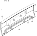
- FIG. 1 is a rear perspective view of a vehicle bumper according to an embodiment of the present invention
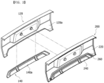
- FIG. 2 is an exploded perspective view of the vehicle bumper according to the embodiment of the present invention
- FIG. 3 is a cross-sectional view of the vehicle bumper.
- a vehicle bumper 1 may include a panel unit 100 and a reinforcing panel 200.
- the panel unit 100 may be disposed at the front of the bonnet or at the rear of the trunk in the longitudinal direction of the vehicle (a direction from a passenger compartment to an engine compartment).
- the panel unit 100 may include a first panel 120 and a second panel 140.
- the first panel 120 may form a main protection area that absorbs impact from a collision.
- the second panel 140 may form an additional protection area on one side (lower side) of the main protection area.
- the first panel 120 and the second panel 140 may be coupled to each other.
- the first panel 120 may include a first cover part 122 and a first coupling part 124.
- the first cover part 122 may be a main component of the first panel 120.
- the first coupling part 124 is disposed on a portion of the edge region of the first cover part 122, and the first coupling part 124 may protrude from a non-exposed surface of the first cover part 122 (hereinafter referred to as "first non-exposed surface").
- the first non-exposed surface 120a may be a surface that is not exposed to the outside of the vehicle in a state in which the first panel 120 is coupled to the vehicle body. That is, in a state in which the first panel 120 is coupled to the vehicle body, the first coupling part 124 may be disposed to face the inside of the vehicle from the first cover part 122.
- the second panel 140 may include a second cover part 142 and a second coupling part 144.
- the second cover part 142 may be a main component of the second panel 140.
- the second cover part 142 may extend from the first cover part 122 of the first panel 120 to form a protection area.
- the second coupling part 144 is disposed on a part of the edge area of the second cover part 142, and the second coupling part 144 may protrude from a non-exposed surface of the second cover part 142 (hereinafter referred to as "second non-exposed surface 140a").
- the second non-exposed surface 140a may be a surface that is not exposed to the outside of the vehicle in a state in which the second panel 140 is coupled to the vehicle body. That is, in a state in which the second panel 140 is coupled to the vehicle body, the second coupling part 144 may be disposed to face the inside of the vehicle from the second cover part 142.
- the panel unit 100 includes the first panel 120 and the second panel 140, but is not limited thereto, and the panel unit 100 may be composed of two or more panels coupled to each other.
- the second coupling part 144 may maintain a state of being in contact with the first coupling part 124.
- lengths of the first coupling part 124 and the second coupling part 144 may be the same, and the lengths of the first coupling part 124 and the second coupling part 144 may be 10 mm or more, but are not limited thereto.
- the lengths of the first coupling part 124 and the second coupling part 144 may be 10 mm or less.
- the contact between the first coupling part 124 and the second coupling part 144 enhances the coupling between the first panel 120 and the second panel 140 while not exposing the coupling structure to the outside, it may be a configuration that improves the design of the panel unit 100.
- the reinforcing panel 200 may be disposed on the non-exposed surfaces (first non-exposed surface 120a and second non-exposed surface 140a) of the first panel 120 and the second panel 140.
- the reinforcing panel 200 may fix the first panel 120 and the second panel 140 to each other.
- the reinforcing panel 200 may include a first reinforcing part 220, a second reinforcing part 240, and a connecting part 260.
- the first reinforcing part 220 may be disposed on the non-exposed surface of the first cover part 122.
- the first reinforcing part 220 may have a thickness corresponding to a thickness of the first cover part 122 of the first panel 120, but is not limited thereto.
- the first reinforcing part 220 may be coupled to the first non-exposed surface 120a of the first cover part 122 of the first panel 120 to reinforce the rigidity of the first panel 120.
- the first reinforcing part 220 may be provided in a shape corresponding to the shape of the first panel 120, but is not limited thereto.
- the second reinforcing part 240 may be disposed on the non-exposed surface of the second cover part 142.
- the second reinforcing part 240 may have a thickness corresponding to a thickness of the second cover part 142 of the second panel 140, but is not limited thereto.
- the second reinforcing part 240 may be spaced apart from the first reinforcing part 220 with the connecting part 260 interposed therebetween.
- the second reinforcing part 240 may be coupled to the second non-exposed surface 140a of the second cover part 142 of the second panel 140 to reinforce the rigidity of the second panel 140.
- the second reinforcing part 240 may be provided in a shape corresponding to the shape of the second panel 140, but is not limited thereto.
- the connecting part 260 may be disposed between the first reinforcing part 220 and the second reinforcing part 240.
- the connecting part 260 may be connected to the first reinforcing part 220 and the second reinforcing part 240 to connect the first reinforcing part 220 and the second reinforcing part 240.
- the connecting part 260 may have a thickness corresponding to a thickness of each of the first coupling part 124 of the first panel 120 and the second coupling part 144 of the second panel 140, but is not limited thereto.
- the connecting part 260 may surround the first coupling part 124 of the first panel 120 and the second coupling part 144 of the second panel 140. More specifically, the connecting part 260 is connected to the first reinforcing part 220 and the second reinforcing part 240 and, since it has a shape similar to " ⁇ ," the connecting part 260 may press the first reinforcing part 220 toward the second reinforcing part 240 and press the second reinforcing part 240 toward the first reinforcing part 220. That is, the connecting part 260 may serve as a clamp to increase the bonding force between the first panel 120 and the second panel 140.
- the non-exposed surfaces of the first panel 120 and the second panel 140 may be coated with the reinforcing panel 200 in the form of a mixture of polyurethane and long glass fibers, and then the reinforcing panel 200 is foamed and shaped in the spaces between the first panel 120, the second panel 140, and the mold disposed on the first panel 120 and the second panel 140.
- a thickness of the reinforcing panel 200 formed in this way may be in the range of 2 mm to 3 mm, but is not limited thereto, and may be changed according to the thickness of the first panel 120 and the second panel 140.
- the reinforcing panel 200 is formed in close contact with the first panel 120 and the second panel 140 while corresponding to the shape of the first panel 120 and the second panel 140 in a coupled state. That is, the reinforcing panel 200 can reduce the need for parts such as existing beams for reinforcing the rigidity of the first panel 120 and the second panel 140. Therefore, the reinforcing panel 200 secures a space between the vehicle bumper 1 and the components facing the vehicle bumper 1, and it is also possible to reduce the weight of the panel unit 100. Therefore, a reduction in weight of a vehicle can be achieved through the reinforcing panel 200. In addition, since the reinforcing panel 200 reinforces the rigidity of the panel unit 100 on the non-exposed surface of the panel unit 100, the degree of freedom in vehicle design can be improved.
- the reinforcing panel 200 has been exemplified as being disposed on the first panel 120 and the second panel 140, but is not limited thereto, and the reinforcing panel 200 may be applied to various parts constituting the exterior of a vehicle.
- the reinforcing panel 200 may be disposed on a non-exposed surface of a fender, disposed on a non-exposed surface of a bonnet, disposed on a non-exposed surface of a trunk and disposed on a non-exposed surface of a door. That is, the reinforcing panel 200 may be applied to any parts forming the exterior of a vehicle to increase the rigidity of the parts forming the exterior of the vehicle.
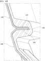
- FIG. 4A is a view showing a first bent part
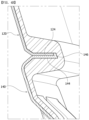
- FIG. 4B is a view showing a second bent part.
- the first panel 120 may further include a first bent part 126.
- the first bent part 126 may be disposed on the first coupling part 124 of the first panel 120.
- the first bent part 126 may have a shape bent from the end of the first coupling part 124.
- a bending direction of the first bent part 126 may correspond to a direction from the first panel 120 toward the second panel 140. Therefore, when the first coupling part 124 of the first panel 120 and the second coupling part 144 of the second panel 140 are coupled, the first bent part 126 is disposed outside the end of the second coupling part 144.
- the first bent part 126 may cover an area in which the first coupling part 124 is in contact with the second coupling part 144. More specifically, the first bent part 126 may cover a gap formed between the first coupling part 124 and the second coupling part 144. That is, when the first panel 120 and the second panel 140 are coated with a mixture of polyurethane and long glass fibers described above, the first bent part 126 may prevent the mixture from flowing into a gap formed by the first coupling part 124 and the second coupling part 144.
- the mixture can prevent an increase of a gap between the first panel 120 and the second panel 140, and a phenomenon in which functions, such as shock absorption and protection from foreign substances, of the panel unit 100 are degraded can be prevented.
- the first bent part 126 may prevent a phenomenon in which the aesthetics of the design of the panel unit 100 is impaired due to the mixture flowing to the exposed surfaces of the first panel 120 and the second panel 140.
- the second panel 140 may further include a second bent part 146.
- the second bent part 146 may be disposed on the second coupling part 144 of the second panel 140.
- the second bent part 146 may have a shape bent from an end of the second coupling part 144.
- a bending direction of the second bent part 146 may correspond to a direction from the second panel 140 toward the first panel 120. Therefore, the second bent part 146 may be disposed outside the end of the first coupling part 124 when the first coupling part 124 of the first panel 120 and the second coupling part 144 of the second panel 140 are coupled.
- the second bent part 146 may cover an area in which the first coupling part 124 is in contact with the second coupling part 144. More specifically, the second bent part 146 may cover a gap formed between the first coupling part 124 and the second coupling part 144. Since the effect of this is the same as that of the first bent part 126, a description thereof will be omitted.
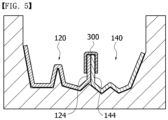
- FIG. 5 is a view showing the blocking member disposed on the first panel and the second panel.
- the vehicle bumper 1 may further include a blocking member 300.
- the blocking member 300 may be disposed at an end portion of the first coupling part 124 of the first panel 120 and an end portion of the second coupling part 144 of the second panel 140.
- the blocking member 300 may close a gap between the first coupling part 124 of the first panel 120 and the second coupling part 144 of the second panel 140.
- the blocking member 300 may be coupled to the first panel 120 and the second panel 140 before the first panel 120 and the second panel 140 are coated with a mixture of polyurethane and long glass fibers. Therefore, the blocking member 300 can prevent the coating mixture from flowing into the gap between the first coupling part 124 and the second coupling part 144.
- the blocking member 300 may be a rubber material strip.
- the strip may have a " ⁇ " cross-sectional shape and may have a length in a direction in which the first coupling part 124 and the second coupling part 144 are disposed.
- the strip-type blocking member 300 may be disposed between the first coupling part 124 of the first panel 120 and the connecting part 260 of the reinforcing panel 200 and disposed between the second coupling part 144 of the second panel 140 and the connecting part 260 of the reinforcing panel 200. Therefore, when the reinforcing panel is formed on the non-exposed sides of the first panel 120 and the second panel 140, as the blocking member 300 is fixed by the reinforcing panel 200, since the holding time of the holding force of the blocking member 300 clamping the first panel 120 and the second panel 140 is increased, the coupled state between the first panel 120 and the second panel 140 can be firmly maintained.
- the blocking member 300 may be a single-sided tape having viscosity.
- the single-sided tape-type blocking member 300 may surround the end portion of the first coupling part 124 in a " ⁇ " shape in the same way as the strip-type blocking member 300, and the viscous surface may close the surface forming a gap between the first coupling part 124 and the second coupling part 144.
- the blocking member 300 may be a staple.
- the staple-type blocking member 300 may pass through one of the first coupling part 124 and the second coupling part 144 and then pass through the other to fix the first coupling part 124 and the second coupling part 144 to each other. Since the staple pulls the first coupling part 124 and the second coupling part 144 toward each other, a gap formed between the first coupling part 124 and the second coupling part 144 may not widen.
- the blocking member 300 may be a clip.
- the clip-type blocking member 300 may have a cross-sectional shape corresponding to the strip-type blocking member 300, and may have a shorter length than the strip-type blocking member 300.
- a plurality of clip-type blocking members 300 may be spaced apart from each other on the first coupling part 124 and the second coupling part 144 coupled to each other.
- the blocking member 300 may be a double-sided tape having viscosity.
- the double-sided tape-type blocking member 300 may be disposed on a surface where the first coupling part 124 and the second coupling part 144 are in contact with each other. Therefore, when the first panel 120 and the second panel 140 are coated with a mixture of polyurethane and long glass fibers, the double-sided tape-type blocking member 300 may prevent the mixture flowing to the exposed surfaces of the first panel 120 and the second panel 140 through the gap formed between the end of the first coupling part 124 and the end of the second coupling part 144 coupled to each other.
- the double-sided tape-type blocking member 300 may be disposed on end surfaces of the first coupler 124 and the second coupler 144 disposed parallel to each other.
- the double-sided tape type blocking member 300 may close a gap formed between the end of the first coupling part 124 and the end of the second coupling part 144 coupled to each other.
- the blocking member 300 may have a shape corresponding to a shape of a portion in which the first coupling part 124 and the second coupling part 144 are coupled to each other.
- the blocking member 3000 may be made of a rigid material (e.g., plastic). That is, when the shapes of the first coupling part 124 and the second coupling part 144 are complicated, a gap formed between the end of the first coupling part 124 and the end of the second coupling part 144 coupled to each other may be closed through the blocking member 300 having a shape corresponding to the shape of the first coupling part 124 and the second coupling part 144.
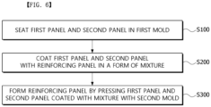
- FIG. 6 is a flow-chart illustrating a method of manufacturing a vehicle bumper
- FIG. 7 is a view showing a reinforcing panel disposed on a first panel and a second panel.
- a method of manufacturing a vehicle bumper 1 may include seating a first panel 120 and a second panel 140 in a first mold (S 100), coating the first panel 120 and the second panel 140 with a reinforcing panel 200 in the form of a mixture (S200), and forming the reinforcing panel 200 by pressing the first panel 120 and the second panel 140 coated with the mixture with a second mold (S300).
- the reinforcing panel 200 in the form of a mixture may be a composition in which polyurethane and long glass fibers are mixed.
- the seating of the first panel 120 and the second panel 140 in the first mold may include a process of arranging the first panel 120 in the first mold so that the exposed surface of the first panel 120 faces the first mold and arranging the second panel 140 in the first mold so that the exposed surface of the second panel 140 faces the first mold.
- the coating of the first panel 120 and the second panel 140 with the reinforcing panel 200 in the form of a mixture through spraying (S200) may include coating the first non-exposed surface 120a of the first panel 120 and the second non-exposed surface 140a of the second panel 140 with the reinforcing panel 200.
- the seating of the first panel 120 and the second panel 140 in the first mold (S100) may include a process of arranging the blocking member 300 on the first panel 120 and the second panel 140 seated in the first mold.
- the blocking member 300 may be omitted according to the shape or coating process of the first panel 120 and the second panel 140.
- the vehicle bumper 1 has a structure in which the reinforcing panel 200 is disposed in close contact with the first panel 120 and the second panel 140, and thus, a reduction in weight and rigidity reinforcement can be simultaneously achieved by the vehicle bumper 1.
- the vehicle bumper since a plurality of a first panel and a second panel in the vehicle bumper are connected through a reinforcing panel, there is no need for parts for connecting a plurality of panels, thereby reducing manufacturing costs and manufacturing time.
- the vehicle bumper since the vehicle bumper has a simplified configuration composed of a panel unit and a reinforcing panel, post-processing time and costs can be reduced.
- the vehicle bumper can have excellent rigidity and heat resistance higher than or equal to those of the conventional bumper.
Landscapes
- Engineering & Computer Science (AREA)
- Mechanical Engineering (AREA)
- Chemical & Material Sciences (AREA)
- Composite Materials (AREA)
- Body Structure For Vehicles (AREA)
Abstract
Description
- This application claims priority to and the benefit of
Korean Patent Application No. 10-2023-0092255, filed on July 17, 2023 - The present invention relates to a vehicle bumper and a method of manufacturing the same.
- A bumper mounted on a vehicle is a component that absorbs impact in the event of a collision and is disposed at the front or rear of the vehicle in the longitudinal direction of the vehicle. Recent bumpers are manufactured through a long fiber injection (LFI) process, and in this case, the bumper may include a panel unit exposed to the outside of the vehicle and a reinforcing part that is combined with the panel unit and reinforces the rigidity of the panel unit.
- The above bumper is formed such that one reinforcing part is coupled to one panel unit. Therefore, compared to injection molding, pressing, painting, and post-processing processes of manufacturing recent bumpers, recent bumpers are subjected to vacuum-forming, foaming, and post-processing, so the costs for manufacturing or using a mold can be reduced, but post-processing costs are relatively high. In addition, since the recent bumpers are formed such that a panel unit and a reinforcing part are manufactured and then combined, there is a problem in that the difficulty of manufacturing and assembling each component increases. Therefore, the need for a process for reinforcing the rigidity of a plurality of panel units in addition to connecting the plurality of panel units into one using the reinforcing part is increasing.
- The present invention is directed to providing an improved vehicle bumper, in which a plurality of panel units are connectable through one reinforcing part, and a method of manufacturing the same.
- According to an aspect of the present invention, there is provided a vehicle bumper includes a panel unit including a first panel forming a main protection area and a second panel coupled to the first panel and forming an additional protection area at one side of the main protection area; and a reinforcing panel disposed on non-exposed surfaces of the first panel and the second panel and fixing the first panel and the second panel to each other.
- The first panel may include a first cover part and a first coupling part, and the second panel may include a second cover part and a second coupling part, wherein the reinforcing panel may include a first reinforcing part disposed on a non-exposed surface of the first cover part, a second reinforcing part disposed on a non-exposed surface of the second cover part, and a connecting part connecting the first reinforcing part and the second reinforcing part and surrounding the first coupling part of the first panel and the second coupling part of the second panel.
- The non-exposed surfaces of the first panel and the second panel may be coated with the reinforcing panel in a form of a mixture of polyurethane and long glass fibers and then foamed and shaped in spaces between the first panel, the second panel, and a mold disposed on the first panel and the second panel.
- The first panel may further include a first bent part having a shape bent from an end of the first coupling part and covering an area in which the first coupling part of the first panel and the second coupling part of the second panel are in contact with each other.
- The second panel may further include a second bent part having a shape bent from an end of the second coupling part and covering an area in which the first coupling part of the first panel and the second coupling part of the second panel are in contact with each other.
- The vehicle bumper may further include a blocking member disposed at an end portion of the first coupling part of the first panel and an end portion of the second coupling part of the second panel and covering between the end portion of the first coupling part of the first panel and the end portion of the second coupling part of the second panel.
- The blocking member may be disposed between the first coupling part of the first panel and the connecting part of the reinforcing panel and disposed between the second coupling part of the second panel and the connecting part of the reinforcing panel.
- In addition, a method of manufacturing a vehicle bumper may include seating a first panel and a second panel in a first mold, coating the first panel and the second panel with a reinforcing panel in the form of a mixture, and forming a reinforcing panel by pressing the first panel and the second panel coated with the mixture is with a second mold.
- The seating of the first panel and the second panel in the first mold may include a process of arranging a blocking member on the first panel and the second panel seated in the first mold.
- The above and other objects, features and advantages of the present invention will become more apparent to those of ordinary skill in the art by describing exemplary embodiments thereof in detail with reference to the accompanying drawings, in which:
-
FIG. 1 is a rear perspective view of a vehicle bumper according to an embodiment of the present invention; -
FIG. 2 is an exploded perspective view of a vehicle bumper according to an embodiment of the present invention; -
FIG. 3 is a cross-sectional view illustrating a vehicle bumper; -
FIG. 4A is a view illustrating a first bent part; -
FIG. 4B is a view illustrating a second bent part; -
FIG. 5 is a view illustrating a blocking member disposed on a first panel and a second panel; -
FIG. 6 is a flowchart illustrating a method of manufacturing a vehicle bumper; and. -
FIG. 7 is a view illustrating a reinforcing panel disposed on a first panel and a second panel. - Since the present invention can undergo various changes and have various embodiments, specific embodiments are illustrated and described in the drawings. However, this is not intended to limit the present invention to specific embodiments, and should be understood to include all modifications, equivalents, and substitutes included in the spirit and scope of the present invention.
- Terms including ordinal numbers, such as first and second, may be used to describe various components, but the components are not limited by these terms. These terms are only used for the purpose of distinguishing one component from another. For example, a second element may be called a first element, and similarly, a first element may be called a second element, without departing from the scope of the present invention. The terms "and/or" include any one or combination of a plurality of related recited items.
- It is understood that when a first element is referred to as being "connected" or "coupled" to a second element, it may be directly connected or coupled to the second element, or a third element may present therebetween. On the other hand, when a first element is referred to as "directly connected" or "directly coupled" to a second element, it should be understood that no other element is disposed therebetween.
- In the description of the embodiment, in the case where one component is described as being formed "on or under" another component, the on or under includes both cases in which there is direct contact between two components and cases in which there is indirect contact by placing one or more other components between the two components. In addition, when expressed as "on or under," it may include the meaning of not only the upward direction but also the downward direction based on one component.
- Terms used in this application are only used to describe specific embodiments, and are not intended to limit the present invention. Singular expressions include plural expressions unless the context clearly dictates otherwise. In this application, although terms such as "include" or "have" are intended to designate the presence of features, numbers, steps, operations, components, parts, or combinations thereof described in the specification, it should be understood that the possibility of the presence or addition of one or more other features numbers, steps, operations, components, parts, or combinations thereof is not precluded.
- Unless defined otherwise, all terms used herein, including technical or scientific terms, have the same meaning as commonly understood by one of ordinary skill in the art to which the present invention belongs. Terms such as those defined in commonly used dictionaries should be interpreted as having a meaning consistent with the meaning in the context of the related art, and unless explicitly defined in this application, it should not be interpreted in an ideal or excessively formal meaning.
- Hereinafter, a vehicle bumper and a method of manufacturing the same will be described in detail with reference to the accompanying drawings, but the same reference numbers will be given to the same or corresponding components regardless of reference numbers, and overlapping descriptions thereof will be omitted.
-
FIG. 1 is a rear perspective view of a vehicle bumper according to an embodiment of the present invention,FIG. 2 is an exploded perspective view of the vehicle bumper according to the embodiment of the present invention, andFIG. 3 is a cross-sectional view of the vehicle bumper. - Referring to
FIGS. 1 to 3 , avehicle bumper 1 according to the embodiment of the present invention may include apanel unit 100 and a reinforcingpanel 200. - As the
panel unit 100 is one component of the vehicle body that forms the exterior of the vehicle, thepanel unit 100 may be disposed at the front of the bonnet or at the rear of the trunk in the longitudinal direction of the vehicle (a direction from a passenger compartment to an engine compartment). Thepanel unit 100 may include afirst panel 120 and asecond panel 140. - The
first panel 120 may form a main protection area that absorbs impact from a collision. Thesecond panel 140 may form an additional protection area on one side (lower side) of the main protection area. Thefirst panel 120 and thesecond panel 140 may be coupled to each other. - The
first panel 120 may include afirst cover part 122 and afirst coupling part 124. - The
first cover part 122 may be a main component of thefirst panel 120. Thefirst coupling part 124 is disposed on a portion of the edge region of thefirst cover part 122, and thefirst coupling part 124 may protrude from a non-exposed surface of the first cover part 122 (hereinafter referred to as "first non-exposed surface"). Here, the firstnon-exposed surface 120a may be a surface that is not exposed to the outside of the vehicle in a state in which thefirst panel 120 is coupled to the vehicle body. That is, in a state in which thefirst panel 120 is coupled to the vehicle body, thefirst coupling part 124 may be disposed to face the inside of the vehicle from thefirst cover part 122. - The
second panel 140 may include asecond cover part 142 and asecond coupling part 144. - The
second cover part 142 may be a main component of thesecond panel 140. Thesecond cover part 142 may extend from thefirst cover part 122 of thefirst panel 120 to form a protection area. Thesecond coupling part 144 is disposed on a part of the edge area of thesecond cover part 142, and thesecond coupling part 144 may protrude from a non-exposed surface of the second cover part 142 (hereinafter referred to as "secondnon-exposed surface 140a"). Here, the secondnon-exposed surface 140a may be a surface that is not exposed to the outside of the vehicle in a state in which thesecond panel 140 is coupled to the vehicle body. That is, in a state in which thesecond panel 140 is coupled to the vehicle body, thesecond coupling part 144 may be disposed to face the inside of the vehicle from thesecond cover part 142. - In this embodiment, the
panel unit 100 includes thefirst panel 120 and thesecond panel 140, but is not limited thereto, and thepanel unit 100 may be composed of two or more panels coupled to each other. - As shown in
FIG. 3 , when thesecond panel 140 is coupled to thefirst panel 120, thesecond coupling part 144 may maintain a state of being in contact with thefirst coupling part 124. At this time, lengths of thefirst coupling part 124 and thesecond coupling part 144 may be the same, and the lengths of thefirst coupling part 124 and thesecond coupling part 144 may be 10 mm or more, but are not limited thereto. The lengths of thefirst coupling part 124 and thesecond coupling part 144 may be 10 mm or less. In this way, as the contact between thefirst coupling part 124 and thesecond coupling part 144 enhances the coupling between thefirst panel 120 and thesecond panel 140 while not exposing the coupling structure to the outside, it may be a configuration that improves the design of thepanel unit 100. - The reinforcing
panel 200 may be disposed on the non-exposed surfaces (firstnon-exposed surface 120a and secondnon-exposed surface 140a) of thefirst panel 120 and thesecond panel 140. The reinforcingpanel 200 may fix thefirst panel 120 and thesecond panel 140 to each other. The reinforcingpanel 200 may include a first reinforcingpart 220, a second reinforcingpart 240, and a connectingpart 260. - The first reinforcing
part 220 may be disposed on the non-exposed surface of thefirst cover part 122. The first reinforcingpart 220 may have a thickness corresponding to a thickness of thefirst cover part 122 of thefirst panel 120, but is not limited thereto. The first reinforcingpart 220 may be coupled to the firstnon-exposed surface 120a of thefirst cover part 122 of thefirst panel 120 to reinforce the rigidity of thefirst panel 120. The first reinforcingpart 220 may be provided in a shape corresponding to the shape of thefirst panel 120, but is not limited thereto. - The second reinforcing
part 240 may be disposed on the non-exposed surface of thesecond cover part 142. The second reinforcingpart 240 may have a thickness corresponding to a thickness of thesecond cover part 142 of thesecond panel 140, but is not limited thereto. The second reinforcingpart 240 may be spaced apart from the first reinforcingpart 220 with the connectingpart 260 interposed therebetween. The second reinforcingpart 240 may be coupled to the secondnon-exposed surface 140a of thesecond cover part 142 of thesecond panel 140 to reinforce the rigidity of thesecond panel 140. The second reinforcingpart 240 may be provided in a shape corresponding to the shape of thesecond panel 140, but is not limited thereto. - The connecting
part 260 may be disposed between the first reinforcingpart 220 and the second reinforcingpart 240. The connectingpart 260 may be connected to the first reinforcingpart 220 and the second reinforcingpart 240 to connect the first reinforcingpart 220 and the second reinforcingpart 240. As shown inFIG. 3 , the connectingpart 260 may have a thickness corresponding to a thickness of each of thefirst coupling part 124 of thefirst panel 120 and thesecond coupling part 144 of thesecond panel 140, but is not limited thereto. - The connecting
part 260 may surround thefirst coupling part 124 of thefirst panel 120 and thesecond coupling part 144 of thesecond panel 140. More specifically, the connectingpart 260 is connected to the first reinforcingpart 220 and the second reinforcingpart 240 and, since it has a shape similar to "□," the connectingpart 260 may press the first reinforcingpart 220 toward the second reinforcingpart 240 and press the second reinforcingpart 240 toward the first reinforcingpart 220. That is, the connectingpart 260 may serve as a clamp to increase the bonding force between thefirst panel 120 and thesecond panel 140. - The non-exposed surfaces of the
first panel 120 and thesecond panel 140 may be coated with the reinforcingpanel 200 in the form of a mixture of polyurethane and long glass fibers, and then the reinforcingpanel 200 is foamed and shaped in the spaces between thefirst panel 120, thesecond panel 140, and the mold disposed on thefirst panel 120 and thesecond panel 140. A thickness of the reinforcingpanel 200 formed in this way may be in the range of 2 mm to 3 mm, but is not limited thereto, and may be changed according to the thickness of thefirst panel 120 and thesecond panel 140. - Therefore, the reinforcing
panel 200 is formed in close contact with thefirst panel 120 and thesecond panel 140 while corresponding to the shape of thefirst panel 120 and thesecond panel 140 in a coupled state. That is, the reinforcingpanel 200 can reduce the need for parts such as existing beams for reinforcing the rigidity of thefirst panel 120 and thesecond panel 140. Therefore, the reinforcingpanel 200 secures a space between thevehicle bumper 1 and the components facing thevehicle bumper 1, and it is also possible to reduce the weight of thepanel unit 100. Therefore, a reduction in weight of a vehicle can be achieved through the reinforcingpanel 200. In addition, since the reinforcingpanel 200 reinforces the rigidity of thepanel unit 100 on the non-exposed surface of thepanel unit 100, the degree of freedom in vehicle design can be improved. - In the above, the reinforcing
panel 200 has been exemplified as being disposed on thefirst panel 120 and thesecond panel 140, but is not limited thereto, and the reinforcingpanel 200 may be applied to various parts constituting the exterior of a vehicle. For example, the reinforcingpanel 200 may be disposed on a non-exposed surface of a fender, disposed on a non-exposed surface of a bonnet, disposed on a non-exposed surface of a trunk and disposed on a non-exposed surface of a door. That is, the reinforcingpanel 200 may be applied to any parts forming the exterior of a vehicle to increase the rigidity of the parts forming the exterior of the vehicle. - Hereinafter, bent parts will be described.
-
FIG. 4A is a view showing a first bent part, andFIG. 4B is a view showing a second bent part. - Referring to
FIG. 4A , thefirst panel 120 may further include a firstbent part 126. The firstbent part 126 may be disposed on thefirst coupling part 124 of thefirst panel 120. The firstbent part 126 may have a shape bent from the end of thefirst coupling part 124. In this case, a bending direction of the firstbent part 126 may correspond to a direction from thefirst panel 120 toward thesecond panel 140. Therefore, when thefirst coupling part 124 of thefirst panel 120 and thesecond coupling part 144 of thesecond panel 140 are coupled, the firstbent part 126 is disposed outside the end of thesecond coupling part 144. - That is, the first
bent part 126 may cover an area in which thefirst coupling part 124 is in contact with thesecond coupling part 144. More specifically, the firstbent part 126 may cover a gap formed between thefirst coupling part 124 and thesecond coupling part 144. That is, when thefirst panel 120 and thesecond panel 140 are coated with a mixture of polyurethane and long glass fibers described above, the firstbent part 126 may prevent the mixture from flowing into a gap formed by thefirst coupling part 124 and thesecond coupling part 144. - Accordingly, the mixture can prevent an increase of a gap between the
first panel 120 and thesecond panel 140, and a phenomenon in which functions, such as shock absorption and protection from foreign substances, of thepanel unit 100 are degraded can be prevented. In addition, the firstbent part 126 may prevent a phenomenon in which the aesthetics of the design of thepanel unit 100 is impaired due to the mixture flowing to the exposed surfaces of thefirst panel 120 and thesecond panel 140. - Referring to
FIG. 4B , thesecond panel 140 may further include a secondbent part 146. The secondbent part 146 may be disposed on thesecond coupling part 144 of thesecond panel 140. The secondbent part 146 may have a shape bent from an end of thesecond coupling part 144. In this case, a bending direction of the secondbent part 146 may correspond to a direction from thesecond panel 140 toward thefirst panel 120. Therefore, the secondbent part 146 may be disposed outside the end of thefirst coupling part 124 when thefirst coupling part 124 of thefirst panel 120 and thesecond coupling part 144 of thesecond panel 140 are coupled. - That is, the second
bent part 146 may cover an area in which thefirst coupling part 124 is in contact with thesecond coupling part 144. More specifically, the secondbent part 146 may cover a gap formed between thefirst coupling part 124 and thesecond coupling part 144. Since the effect of this is the same as that of the firstbent part 126, a description thereof will be omitted. - Hereinafter, the blocking
member 300 will be described. -
FIG. 5 is a view showing the blocking member disposed on the first panel and the second panel. - Referring to
FIG. 5 , thevehicle bumper 1 may further include a blockingmember 300. The blockingmember 300 may be disposed at an end portion of thefirst coupling part 124 of thefirst panel 120 and an end portion of thesecond coupling part 144 of thesecond panel 140. The blockingmember 300 may close a gap between thefirst coupling part 124 of thefirst panel 120 and thesecond coupling part 144 of thesecond panel 140. The blockingmember 300 may be coupled to thefirst panel 120 and thesecond panel 140 before thefirst panel 120 and thesecond panel 140 are coated with a mixture of polyurethane and long glass fibers. Therefore, the blockingmember 300 can prevent the coating mixture from flowing into the gap between thefirst coupling part 124 and thesecond coupling part 144. - As shown in
FIG. 5 , the blockingmember 300 may be a rubber material strip. In this case, the strip may have a "□" cross-sectional shape and may have a length in a direction in which thefirst coupling part 124 and thesecond coupling part 144 are disposed. - That is, the strip-
type blocking member 300 may be disposed between thefirst coupling part 124 of thefirst panel 120 and the connectingpart 260 of the reinforcingpanel 200 and disposed between thesecond coupling part 144 of thesecond panel 140 and the connectingpart 260 of the reinforcingpanel 200. Therefore, when the reinforcing panel is formed on the non-exposed sides of thefirst panel 120 and thesecond panel 140, as the blockingmember 300 is fixed by the reinforcingpanel 200, since the holding time of the holding force of the blockingmember 300 clamping thefirst panel 120 and thesecond panel 140 is increased, the coupled state between thefirst panel 120 and thesecond panel 140 can be firmly maintained. - The blocking
member 300 may be a single-sided tape having viscosity. The single-sided tape-type blocking member 300 may surround the end portion of thefirst coupling part 124 in a "□" shape in the same way as the strip-type blocking member 300, and the viscous surface may close the surface forming a gap between thefirst coupling part 124 and thesecond coupling part 144. - The blocking
member 300 may be a staple. The staple-type blocking member 300 may pass through one of thefirst coupling part 124 and thesecond coupling part 144 and then pass through the other to fix thefirst coupling part 124 and thesecond coupling part 144 to each other. Since the staple pulls thefirst coupling part 124 and thesecond coupling part 144 toward each other, a gap formed between thefirst coupling part 124 and thesecond coupling part 144 may not widen. - The blocking
member 300 may be a clip. The clip-type blocking member 300 may have a cross-sectional shape corresponding to the strip-type blocking member 300, and may have a shorter length than the strip-type blocking member 300. A plurality of clip-type blocking members 300 may be spaced apart from each other on thefirst coupling part 124 and thesecond coupling part 144 coupled to each other. - The blocking
member 300 may be a double-sided tape having viscosity. The double-sided tape-type blocking member 300 may be disposed on a surface where thefirst coupling part 124 and thesecond coupling part 144 are in contact with each other. Therefore, when thefirst panel 120 and thesecond panel 140 are coated with a mixture of polyurethane and long glass fibers, the double-sided tape-type blocking member 300 may prevent the mixture flowing to the exposed surfaces of thefirst panel 120 and thesecond panel 140 through the gap formed between the end of thefirst coupling part 124 and the end of thesecond coupling part 144 coupled to each other. - In addition, the double-sided tape-
type blocking member 300 may be disposed on end surfaces of thefirst coupler 124 and thesecond coupler 144 disposed parallel to each other. Thus, the double-sided tapetype blocking member 300 may close a gap formed between the end of thefirst coupling part 124 and the end of thesecond coupling part 144 coupled to each other.. - In addition, the blocking
member 300 may have a shape corresponding to a shape of a portion in which thefirst coupling part 124 and thesecond coupling part 144 are coupled to each other. In this case, the blocking member 3000 may be made of a rigid material (e.g., plastic). That is, when the shapes of thefirst coupling part 124 and thesecond coupling part 144 are complicated, a gap formed between the end of thefirst coupling part 124 and the end of thesecond coupling part 144 coupled to each other may be closed through the blockingmember 300 having a shape corresponding to the shape of thefirst coupling part 124 and thesecond coupling part 144. - Hereinafter, a process of manufacturing a
vehicle bumper 1 will be described. -
FIG. 6 is a flow-chart illustrating a method of manufacturing a vehicle bumper, andFIG. 7 is a view showing a reinforcing panel disposed on a first panel and a second panel. - Referring to
FIGS. 6 and7 , a method of manufacturing avehicle bumper 1 may include seating afirst panel 120 and asecond panel 140 in a first mold (S 100), coating thefirst panel 120 and thesecond panel 140 with a reinforcingpanel 200 in the form of a mixture (S200), and forming the reinforcingpanel 200 by pressing thefirst panel 120 and thesecond panel 140 coated with the mixture with a second mold (S300). Here, the reinforcingpanel 200 in the form of a mixture may be a composition in which polyurethane and long glass fibers are mixed. - As shown in
FIG. 7 , the seating of thefirst panel 120 and thesecond panel 140 in the first mold (S 100) may include a process of arranging thefirst panel 120 in the first mold so that the exposed surface of thefirst panel 120 faces the first mold and arranging thesecond panel 140 in the first mold so that the exposed surface of thesecond panel 140 faces the first mold. - In addition, the coating of the
first panel 120 and thesecond panel 140 with the reinforcingpanel 200 in the form of a mixture through spraying (S200) may include coating the firstnon-exposed surface 120a of thefirst panel 120 and the secondnon-exposed surface 140a of thesecond panel 140 with the reinforcingpanel 200. - In addition, the seating of the
first panel 120 and thesecond panel 140 in the first mold (S100) may include a process of arranging the blockingmember 300 on thefirst panel 120 and thesecond panel 140 seated in the first mold. The blockingmember 300 may be omitted according to the shape or coating process of thefirst panel 120 and thesecond panel 140. - As such, after the
first panel 120 and thesecond panel 140 are coated with the mixture, when the second mold presses thefirst panel 120 and thesecond panel 140, as the mixture is foamed by the pressing force and the heat generated by the pressing force, the shape of the reinforcingpanel 200 may be determined by filling a space formed by thefirst panel 120, thesecond panel 140, and the second mold with the mixture. Therefore, thevehicle bumper 1 has a structure in which the reinforcingpanel 200 is disposed in close contact with thefirst panel 120 and thesecond panel 140, and thus, a reduction in weight and rigidity reinforcement can be simultaneously achieved by thevehicle bumper 1. - According to one embodiment, since a plurality of a first panel and a second panel in the vehicle bumper are connected through a reinforcing panel, there is no need for parts for connecting a plurality of panels, thereby reducing manufacturing costs and manufacturing time. In addition, since the vehicle bumper has a simplified configuration composed of a panel unit and a reinforcing panel, post-processing time and costs can be reduced.
- In addition, through a reinforcing panel, the vehicle bumper can have excellent rigidity and heat resistance higher than or equal to those of the conventional bumper.
- Although the above description has been given with reference to embodiments of the present invention, those skilled in the art can variously modify and change the present invention within the scope not departing from the spirit and scope of the present invention described in the claims below. Also, it should be construed that the differences related to these modifications and changes are included in the scope of the present invention, which is defined in the appended claims.
Claims (10)
- A vehicle bumper comprising:a panel unit including a first panel having a main protection area and a second panel coupled to the first panel and having an additional protection area at one side of the main protection area; anda reinforcing panel disposed on non-exposed surfaces of the first panel and the second panel and fixing the first panel and the second panel to each other.
- The vehicle bumper of claim 1, wherein the first panel includes a first cover part and a first coupling part,the second panel includes a second cover part and a second coupling part, andthe reinforcing panel includes a first reinforcing part disposed on a non-exposed surface of the first cover part, a second reinforcing part disposed on a non-exposed surface of the second cover part, and a connecting part connecting the first reinforcing part and the second reinforcing part and surrounding the first coupling part of the first panel and the second coupling part of the second panel.
- The vehicle bumper of claim 2, wherein the first panel further includes a first bent part having a shape bent from an end of the first coupling part and covering an area in which the first coupling part of the first panel and the second coupling part of the second panel are in contact with each other.
- The vehicle bumper of claim 2 or 3, wherein the second panel further includes a second bent part having a shape bent from an end of the second coupling part and covering an area in which the first coupling part of the first panel and the second coupling part of the second panel are in contact with each other.
- The vehicle bumper of any one of claims 2 to 4, further comprising a blocking member disposed at an end portion of the first coupling part of the first panel and an end portion of the second coupling part of the second panel and covering between the end portion of the first coupling part of the first panel and the end portion of the second coupling part of the second panel.
- The vehicle bumper of claim 6, wherein the blocking member is disposed between the first coupling part of the first panel and the connecting part of the reinforcing panel and disposed between the second coupling part of the second panel and the connecting part of the reinforcing panel.
- The vehicle bumper of any one of claims 1 to 6, wherein the non-exposed surfaces of the first panel and the second panel are coated with the reinforcing panel in a form of a mixture of polyurethane and long glass fibers and then the reinforcing panel is foamed and shaped in spaces between the first panel, the second panel, and a mold disposed on the first panel and the second panel.
- The vehicle bumper of any one of claims 1 to 7, wherein the reinforcing panel, including a mixture of polyurethane and glass fibers, is disposed on the first panel and the second panel.
- A method of manufacturing a vehicle bumper, comprising:placing a first panel and a second panel in a first mold;coating the first panel and the second panel with a mixture; andforming a reinforcing panel by pressing the first panel and the second panel coated with the mixture with a second mold.
- The method of claim 9, wherein the placing of the first panel and the second panel in the first mold includes a process of arranging a blocking member on the first panel and the second panel in the first mold.
Applications Claiming Priority (1)
| Application Number | Priority Date | Filing Date | Title |
|---|---|---|---|
| KR1020230092255A KR102826805B1 (en) | 2023-07-17 | 2023-07-17 | Bumper for vehicle and manufacturing method the same |
Publications (2)
| Publication Number | Publication Date |
|---|---|
| EP4494947A1 true EP4494947A1 (en) | 2025-01-22 |
| EP4494947B1 EP4494947B1 (en) | 2026-04-22 |
Family
ID=88779144
Family Applications (1)
| Application Number | Title | Priority Date | Filing Date |
|---|---|---|---|
| EP23208877.3A Active EP4494947B1 (en) | 2023-07-17 | 2023-11-09 | Vehicle bumper and method of manufacturing the same |
Country Status (4)
| Country | Link |
|---|---|
| US (1) | US20250026289A1 (en) |
| EP (1) | EP4494947B1 (en) |
| KR (1) | KR102826805B1 (en) |
| CN (1) | CN119348558A (en) |
Families Citing this family (2)
| Publication number | Priority date | Publication date | Assignee | Title |
|---|---|---|---|---|
| USD1022814S1 (en) * | 2022-03-31 | 2024-04-16 | Zoox, Inc. | Grille assembly |
| KR20250012255A (en) * | 2023-07-17 | 2025-01-24 | 현대모비스 주식회사 | Bumper for vehicle |
Citations (1)
| Publication number | Priority date | Publication date | Assignee | Title |
|---|---|---|---|---|
| US4171143A (en) * | 1976-10-30 | 1979-10-16 | Daimler-Benz Ag | Bumper for a motor vehicle |
Family Cites Families (5)
| Publication number | Priority date | Publication date | Assignee | Title |
|---|---|---|---|---|
| KR970041157A (en) * | 1995-12-27 | 1997-07-24 | 한승준 | Body reinforcement structure |
| KR19980036096U (en) * | 1996-12-13 | 1998-09-15 | 김영귀 | Bumper Structure of Car |
| JP3104462U (en) * | 2004-04-06 | 2004-09-16 | 株式会社ミドー | Automotive in-dash device |
| JP5509863B2 (en) | 2010-01-14 | 2014-06-04 | トヨタ自動車株式会社 | Pedestrian collision detection device |
| JP2019214434A (en) * | 2018-06-11 | 2019-12-19 | セイコーエプソン株式会社 | Recording device |
-
2023
- 2023-07-17 KR KR1020230092255A patent/KR102826805B1/en active Active
- 2023-11-09 EP EP23208877.3A patent/EP4494947B1/en active Active
- 2023-11-27 US US18/519,380 patent/US20250026289A1/en active Pending
-
2024
- 2024-03-06 CN CN202410256229.5A patent/CN119348558A/en active Pending
Patent Citations (1)
| Publication number | Priority date | Publication date | Assignee | Title |
|---|---|---|---|---|
| US4171143A (en) * | 1976-10-30 | 1979-10-16 | Daimler-Benz Ag | Bumper for a motor vehicle |
Also Published As
| Publication number | Publication date |
|---|---|
| US20250026289A1 (en) | 2025-01-23 |
| CN119348558A (en) | 2025-01-24 |
| KR102826805B1 (en) | 2025-07-01 |
| EP4494947B1 (en) | 2026-04-22 |
| KR20250012256A (en) | 2025-01-24 |
Similar Documents
| Publication | Publication Date | Title |
|---|---|---|
| EP3372454B1 (en) | Vehicle body structure | |
| EP4494947A1 (en) | Vehicle bumper and method of manufacturing the same | |
| US10399520B2 (en) | Vehicle body structure | |
| EP2990246B1 (en) | Vehicular door structure | |
| US5580116A (en) | Trim component having energy absorbing feature | |
| JP3223896B2 (en) | Impact energy absorbing structure on top of car body | |
| US12134423B2 (en) | Front vehicle body structure | |
| US12240299B2 (en) | Vehicle door structure | |
| CN113085503A (en) | Door for vehicle | |
| JP5867062B2 (en) | Resin panel joint structure | |
| JP3949138B2 (en) | End wall module | |
| JP7460924B2 (en) | Shock absorber | |
| WO2019026967A1 (en) | Impact absorbing body | |
| US5868458A (en) | Interior material for automotive vehicle | |
| JP3838555B2 (en) | Armrest structure for interior parts | |
| JP7765719B2 (en) | shock absorber | |
| US5586797A (en) | Automotive door assembly | |
| KR102869094B1 (en) | Sidesill strucutre for vehicle | |
| US12258073B2 (en) | Unitary structural component for vehicle floor | |
| US11794669B2 (en) | Fastening structure for vehicle | |
| KR100831501B1 (en) | Quarter glass for SW with improved mounting structure | |
| KR102022550B1 (en) | Lightweight tailgate assembly | |
| JPH07137539A (en) | Car body structure | |
| JP4292058B2 (en) | Vehicle interior ceiling parts | |
| JP6036924B2 (en) | Resin panel joint structure |
Legal Events
| Date | Code | Title | Description |
|---|---|---|---|
| PUAI | Public reference made under article 153(3) epc to a published international application that has entered the european phase |
Free format text: ORIGINAL CODE: 0009012 |
|
| STAA | Information on the status of an ep patent application or granted ep patent |
Free format text: STATUS: REQUEST FOR EXAMINATION WAS MADE |
|
| 17P | Request for examination filed |
Effective date: 20231209 |
|
| AK | Designated contracting states |
Kind code of ref document: A1 Designated state(s): AL AT BE BG CH CY CZ DE DK EE ES FI FR GB GR HR HU IE IS IT LI LT LU LV MC ME MK MT NL NO PL PT RO RS SE SI SK SM TR |
|
| STAA | Information on the status of an ep patent application or granted ep patent |
Free format text: STATUS: EXAMINATION IS IN PROGRESS |
|
| 17Q | First examination report despatched |
Effective date: 20250702 |
|
| GRAP | Despatch of communication of intention to grant a patent |
Free format text: ORIGINAL CODE: EPIDOSNIGR1 |
|
| STAA | Information on the status of an ep patent application or granted ep patent |
Free format text: STATUS: GRANT OF PATENT IS INTENDED |
|
| INTG | Intention to grant announced |
Effective date: 20260128 |
|
| GRAS | Grant fee paid |
Free format text: ORIGINAL CODE: EPIDOSNIGR3 |
|
| GRAA | (expected) grant |
Free format text: ORIGINAL CODE: 0009210 |
|
| STAA | Information on the status of an ep patent application or granted ep patent |
Free format text: STATUS: THE PATENT HAS BEEN GRANTED |
|
| P01 | Opt-out of the competence of the unified patent court (upc) registered |
Free format text: CASE NUMBER: UPC_APP_0009622_4494947/2026 Effective date: 20260311 |
|
| AK | Designated contracting states |
Kind code of ref document: B1 Designated state(s): AL AT BE BG CH CY CZ DE DK EE ES FI FR GB GR HR HU IE IS IT LI LT LU LV MC ME MK MT NL NO PL PT RO RS SE SI SK SM TR |
|
| REG | Reference to a national code |
Ref country code: CH Ref legal event code: F10 Free format text: ST27 STATUS EVENT CODE: U-0-0-F10-F00 (AS PROVIDED BY THE NATIONAL OFFICE) Effective date: 20260422 Ref country code: GB Ref legal event code: FG4D |