EP4494774A1 - Wickelsystem und -verfahren für gewalzte produkte - Google Patents
Wickelsystem und -verfahren für gewalzte produkte Download PDFInfo
- Publication number
- EP4494774A1 EP4494774A1 EP24187808.1A EP24187808A EP4494774A1 EP 4494774 A1 EP4494774 A1 EP 4494774A1 EP 24187808 A EP24187808 A EP 24187808A EP 4494774 A1 EP4494774 A1 EP 4494774A1
- Authority
- EP
- European Patent Office
- Prior art keywords
- spool
- rolled product
- winding
- coil
- distributor
- Prior art date
- Legal status (The legal status is an assumption and is not a legal conclusion. Google has not performed a legal analysis and makes no representation as to the accuracy of the status listed.)
- Granted
Links
Images




Classifications
-
- B—PERFORMING OPERATIONS; TRANSPORTING
- B21—MECHANICAL METAL-WORKING WITHOUT ESSENTIALLY REMOVING MATERIAL; PUNCHING METAL
- B21C—MANUFACTURE OF METAL SHEETS, WIRE, RODS, TUBES, PROFILES OR LIKE SEMI-MANUFACTURED PRODUCTS OTHERWISE THAN BY ROLLING; AUXILIARY OPERATIONS USED IN CONNECTION WITH METAL-WORKING WITHOUT ESSENTIALLY REMOVING MATERIAL
- B21C47/00—Winding-up, coiling or winding-off metal wire, metal band or other flexible metal material characterised by features relevant to metal processing only
- B21C47/02—Winding-up or coiling
- B21C47/10—Winding-up or coiling by means of a moving guide
- B21C47/14—Winding-up or coiling by means of a moving guide by means of a rotating guide, e.g. laying the material around a stationary reel or drum
- B21C47/146—Controlling or influencing the laying pattern of the coils
-
- B—PERFORMING OPERATIONS; TRANSPORTING
- B21—MECHANICAL METAL-WORKING WITHOUT ESSENTIALLY REMOVING MATERIAL; PUNCHING METAL
- B21B—ROLLING OF METAL
- B21B15/00—Arrangements for performing additional metal-working operations specially combined with or arranged in, or specially adapted for use in connection with, metal-rolling mills
-
- B—PERFORMING OPERATIONS; TRANSPORTING
- B21—MECHANICAL METAL-WORKING WITHOUT ESSENTIALLY REMOVING MATERIAL; PUNCHING METAL
- B21C—MANUFACTURE OF METAL SHEETS, WIRE, RODS, TUBES, PROFILES OR LIKE SEMI-MANUFACTURED PRODUCTS OTHERWISE THAN BY ROLLING; AUXILIARY OPERATIONS USED IN CONNECTION WITH METAL-WORKING WITHOUT ESSENTIALLY REMOVING MATERIAL
- B21C47/00—Winding-up, coiling or winding-off metal wire, metal band or other flexible metal material characterised by features relevant to metal processing only
- B21C47/003—Regulation of tension or speed; Braking
-
- B—PERFORMING OPERATIONS; TRANSPORTING
- B65—CONVEYING; PACKING; STORING; HANDLING THIN OR FILAMENTARY MATERIAL
- B65H—HANDLING THIN OR FILAMENTARY MATERIAL, e.g. SHEETS, WEBS, CABLES
- B65H54/00—Winding, coiling, or depositing filamentary material
- B65H54/02—Winding and traversing material on to reels, bobbins, tubes, or like package cores or formers
- B65H54/28—Traversing devices; Package-shaping arrangements
- B65H54/2848—Arrangements for aligned winding
- B65H54/2854—Detection or control of aligned winding or reversal
- B65H54/2869—Control of the rotating speed of the reel or the traversing speed for aligned winding
- B65H54/2875—Control of the rotating speed of the reel or the traversing speed for aligned winding by detecting or following the already wound material, e.g. contour following
-
- B—PERFORMING OPERATIONS; TRANSPORTING
- B21—MECHANICAL METAL-WORKING WITHOUT ESSENTIALLY REMOVING MATERIAL; PUNCHING METAL
- B21C—MANUFACTURE OF METAL SHEETS, WIRE, RODS, TUBES, PROFILES OR LIKE SEMI-MANUFACTURED PRODUCTS OTHERWISE THAN BY ROLLING; AUXILIARY OPERATIONS USED IN CONNECTION WITH METAL-WORKING WITHOUT ESSENTIALLY REMOVING MATERIAL
- B21C47/00—Winding-up, coiling or winding-off metal wire, metal band or other flexible metal material characterised by features relevant to metal processing only
- B21C47/02—Winding-up or coiling
- B21C47/04—Winding-up or coiling on or in reels or drums, without using a moving guide
-
- B—PERFORMING OPERATIONS; TRANSPORTING
- B21—MECHANICAL METAL-WORKING WITHOUT ESSENTIALLY REMOVING MATERIAL; PUNCHING METAL
- B21C—MANUFACTURE OF METAL SHEETS, WIRE, RODS, TUBES, PROFILES OR LIKE SEMI-MANUFACTURED PRODUCTS OTHERWISE THAN BY ROLLING; AUXILIARY OPERATIONS USED IN CONNECTION WITH METAL-WORKING WITHOUT ESSENTIALLY REMOVING MATERIAL
- B21C47/00—Winding-up, coiling or winding-off metal wire, metal band or other flexible metal material characterised by features relevant to metal processing only
- B21C47/02—Winding-up or coiling
- B21C47/10—Winding-up or coiling by means of a moving guide
- B21C47/12—Winding-up or coiling by means of a moving guide the guide moving parallel to the axis of the coil
-
- B—PERFORMING OPERATIONS; TRANSPORTING
- B21—MECHANICAL METAL-WORKING WITHOUT ESSENTIALLY REMOVING MATERIAL; PUNCHING METAL
- B21C—MANUFACTURE OF METAL SHEETS, WIRE, RODS, TUBES, PROFILES OR LIKE SEMI-MANUFACTURED PRODUCTS OTHERWISE THAN BY ROLLING; AUXILIARY OPERATIONS USED IN CONNECTION WITH METAL-WORKING WITHOUT ESSENTIALLY REMOVING MATERIAL
- B21C47/00—Winding-up, coiling or winding-off metal wire, metal band or other flexible metal material characterised by features relevant to metal processing only
- B21C47/26—Special arrangements with regard to simultaneous or subsequent treatment of the material
- B21C47/262—Treatment of a wire, while in the form of overlapping non-concentric rings
-
- B—PERFORMING OPERATIONS; TRANSPORTING
- B21—MECHANICAL METAL-WORKING WITHOUT ESSENTIALLY REMOVING MATERIAL; PUNCHING METAL
- B21C—MANUFACTURE OF METAL SHEETS, WIRE, RODS, TUBES, PROFILES OR LIKE SEMI-MANUFACTURED PRODUCTS OTHERWISE THAN BY ROLLING; AUXILIARY OPERATIONS USED IN CONNECTION WITH METAL-WORKING WITHOUT ESSENTIALLY REMOVING MATERIAL
- B21C47/00—Winding-up, coiling or winding-off metal wire, metal band or other flexible metal material characterised by features relevant to metal processing only
- B21C47/34—Feeding or guiding devices not specially adapted to a particular type of apparatus
-
- B—PERFORMING OPERATIONS; TRANSPORTING
- B21—MECHANICAL METAL-WORKING WITHOUT ESSENTIALLY REMOVING MATERIAL; PUNCHING METAL
- B21C—MANUFACTURE OF METAL SHEETS, WIRE, RODS, TUBES, PROFILES OR LIKE SEMI-MANUFACTURED PRODUCTS OTHERWISE THAN BY ROLLING; AUXILIARY OPERATIONS USED IN CONNECTION WITH METAL-WORKING WITHOUT ESSENTIALLY REMOVING MATERIAL
- B21C47/00—Winding-up, coiling or winding-off metal wire, metal band or other flexible metal material characterised by features relevant to metal processing only
- B21C47/34—Feeding or guiding devices not specially adapted to a particular type of apparatus
- B21C47/3408—Feeding or guiding devices not specially adapted to a particular type of apparatus for monitoring the lateral position of the material
-
- B—PERFORMING OPERATIONS; TRANSPORTING
- B21—MECHANICAL METAL-WORKING WITHOUT ESSENTIALLY REMOVING MATERIAL; PUNCHING METAL
- B21C—MANUFACTURE OF METAL SHEETS, WIRE, RODS, TUBES, PROFILES OR LIKE SEMI-MANUFACTURED PRODUCTS OTHERWISE THAN BY ROLLING; AUXILIARY OPERATIONS USED IN CONNECTION WITH METAL-WORKING WITHOUT ESSENTIALLY REMOVING MATERIAL
- B21C47/00—Winding-up, coiling or winding-off metal wire, metal band or other flexible metal material characterised by features relevant to metal processing only
- B21C47/34—Feeding or guiding devices not specially adapted to a particular type of apparatus
- B21C47/3408—Feeding or guiding devices not specially adapted to a particular type of apparatus for monitoring the lateral position of the material
- B21C47/3425—Feeding or guiding devices not specially adapted to a particular type of apparatus for monitoring the lateral position of the material without lateral edge contact
-
- B—PERFORMING OPERATIONS; TRANSPORTING
- B21—MECHANICAL METAL-WORKING WITHOUT ESSENTIALLY REMOVING MATERIAL; PUNCHING METAL
- B21C—MANUFACTURE OF METAL SHEETS, WIRE, RODS, TUBES, PROFILES OR LIKE SEMI-MANUFACTURED PRODUCTS OTHERWISE THAN BY ROLLING; AUXILIARY OPERATIONS USED IN CONNECTION WITH METAL-WORKING WITHOUT ESSENTIALLY REMOVING MATERIAL
- B21C47/00—Winding-up, coiling or winding-off metal wire, metal band or other flexible metal material characterised by features relevant to metal processing only
- B21C47/34—Feeding or guiding devices not specially adapted to a particular type of apparatus
- B21C47/345—Feeding or guiding devices not specially adapted to a particular type of apparatus for monitoring the tension or advance of the material
-
- B—PERFORMING OPERATIONS; TRANSPORTING
- B21—MECHANICAL METAL-WORKING WITHOUT ESSENTIALLY REMOVING MATERIAL; PUNCHING METAL
- B21C—MANUFACTURE OF METAL SHEETS, WIRE, RODS, TUBES, PROFILES OR LIKE SEMI-MANUFACTURED PRODUCTS OTHERWISE THAN BY ROLLING; AUXILIARY OPERATIONS USED IN CONNECTION WITH METAL-WORKING WITHOUT ESSENTIALLY REMOVING MATERIAL
- B21C51/00—Measuring, gauging, indicating, counting, or marking devices specially adapted for use in the production or manipulation of material in accordance with subclasses B21B - B21F
-
- G—PHYSICS
- G01—MEASURING; TESTING
- G01B—MEASURING LENGTH, THICKNESS OR SIMILAR LINEAR DIMENSIONS; MEASURING ANGLES; MEASURING AREAS; MEASURING IRREGULARITIES OF SURFACES OR CONTOURS
- G01B11/00—Measuring arrangements characterised by the use of optical techniques
- G01B11/08—Measuring arrangements characterised by the use of optical techniques for measuring diameters
- G01B11/10—Measuring arrangements characterised by the use of optical techniques for measuring diameters of objects while moving
- G01B11/105—Measuring arrangements characterised by the use of optical techniques for measuring diameters of objects while moving using photoelectric detection means
-
- G—PHYSICS
- G01—MEASURING; TESTING
- G01B—MEASURING LENGTH, THICKNESS OR SIMILAR LINEAR DIMENSIONS; MEASURING ANGLES; MEASURING AREAS; MEASURING IRREGULARITIES OF SURFACES OR CONTOURS
- G01B11/00—Measuring arrangements characterised by the use of optical techniques
- G01B11/30—Measuring arrangements characterised by the use of optical techniques for measuring roughness or irregularity of surfaces
-
- B—PERFORMING OPERATIONS; TRANSPORTING
- B21—MECHANICAL METAL-WORKING WITHOUT ESSENTIALLY REMOVING MATERIAL; PUNCHING METAL
- B21B—ROLLING OF METAL
- B21B15/00—Arrangements for performing additional metal-working operations specially combined with or arranged in, or specially adapted for use in connection with, metal-rolling mills
- B21B2015/0057—Coiling the rolled product
-
- B—PERFORMING OPERATIONS; TRANSPORTING
- B65—CONVEYING; PACKING; STORING; HANDLING THIN OR FILAMENTARY MATERIAL
- B65H—HANDLING THIN OR FILAMENTARY MATERIAL, e.g. SHEETS, WEBS, CABLES
- B65H2511/00—Dimensions; Position; Numbers; Identification; Occurrences
- B65H2511/10—Size; Dimensions
- B65H2511/14—Diameter, e.g. of roll or package
-
- B—PERFORMING OPERATIONS; TRANSPORTING
- B65—CONVEYING; PACKING; STORING; HANDLING THIN OR FILAMENTARY MATERIAL
- B65H—HANDLING THIN OR FILAMENTARY MATERIAL, e.g. SHEETS, WEBS, CABLES
- B65H2557/00—Means for control not provided for in groups B65H2551/00 - B65H2555/00
- B65H2557/50—Use of particular electromagnetic waves, e.g. light, radiowaves or microwaves
- B65H2557/51—Laser
-
- B—PERFORMING OPERATIONS; TRANSPORTING
- B65—CONVEYING; PACKING; STORING; HANDLING THIN OR FILAMENTARY MATERIAL
- B65H—HANDLING THIN OR FILAMENTARY MATERIAL, e.g. SHEETS, WEBS, CABLES
- B65H54/00—Winding, coiling, or depositing filamentary material
- B65H54/02—Winding and traversing material on to reels, bobbins, tubes, or like package cores or formers
- B65H54/28—Traversing devices; Package-shaping arrangements
Definitions
- the present invention relates to a system and method for winding rolled products in the field of the steel industry.
- the present invention allows controlling, regulating and commanding the hot or cold winding of semi-finished metal products coming from steel mills, such as wire rod, wire, tubular elements or the like, used, for example, in the production of metal structures, e.g., to obtain reinforced concrete or other types of structures.
- Winding systems suitable for making coils of hot or cold semi-finished metal products coming from, for example, steel mills, or secondary processing products, such as wire rod, wire, tubular elements, squares or the like, are known.
- the various types of metal products will all be generally referred to as rods in the following description.
- the rod has a non-uniform surface conformation, characterized by the presence of edges or corrugations which change its cross section. This affects the winding in the coil.
- the rod is often wound when it is still hot or very hot. This affects the section with which the rod is wound and thus the winding in the coil.
- the winding systems comprise:
- the coiler normally comprises a spindle associated with retaining elements which define the width of the coil, at least one of which is removable for extracting the coil.
- the rotating coiler can be arranged with its rotation axis either vertically or horizontally. In both cases, the distributor is positioned to the side of the rotating coiler.
- the distributor In use, the distributor is moved as a shuttle between the two axial ends of the coiler. Such a movement occurs in a plane parallel to the rotation axis of the coiler. Such a plane may pass through the axis of the coiler or be kept tangent to the cylindrical surface of varying diameter of the coil in formation.
- the winding is certainly affected by the cross-section of the rod and its variability. Therefore, it is not enough to know the nominal values of the rod section to obtain sufficiently precise control of the coil formation to optimize the filling speed and avoid overlaps and/or gaps between adjacent turns.
- the winding systems of the conventional type cannot optimally coordinate the functionality of either the coiler or the distributor so that the turns are positioned in the desired manner, relative to the optimization parameters above, according to the cross section and characteristics of the rod.
- the incorrect arrangement of the turns during winding generates imperfections in the resulting coil, e.g., such as gaps and/or overlaps, partial or total, of the turns.
- the coils obtained from known systems, due to their imperfections, may therefore have a low coil density coefficient, defined as the ratio of the effective volume of the coils to the total overall footprint of the coil.
- control and regulation devices which can measure some parameters, including the rod distribution speed, and can use the information gathered to control and manage winding.
- these known devices are unreliable in measuring parameters, which is done indirectly. This means that the consequent adjustment of the rotation speed of the coiler, and/or of the displacement speed and/or of the distributor positioning is/are also inaccurate.
- these known devices are not only unable to detect the cross-section of the rod, but must also be constantly coordinated with the distributor and must be replaced and/or adjusted from time to time according to the cross-section of the rod.
- such a management device is intended to cooperate with a winding apparatus, which is provided with: a distributor B having a feed outlet C of hot or cold semi-finished metal products; and a spool D. Distributor and spool are respectively moved by appropriate controlled movement and rotation means.
- the management device comprises:
- the management method comprises the following operating steps:
- the management method of a winder described in EP3362390B1 while allowing for a marked improvement in spool quality, is not easy to implement because the step of detecting of the control parameters must be performed on the semi-finished product at the instantaneous point of winding of the metal semi-finished product onto the spool D, a position in which the semi-finished product is more affected by vibrations than when it is wound on the spool. Therefore, the detection of the inclination angle is affected by vibratory phenomena induced by the rotation of the winder and the feeding motion of the semi-finished product. To avoid loosing accuracy, such a step of detecting must be conducted in a particularly accurate manner. This complicates the management method.
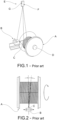
- a rolled product winding system in the field of the steel industry according to the invention is indicated by reference numeral 1 as a whole.
- the winding system 1 is intended to be installed in a rolling line 100 suitable to produce a rolled product. More in detail, the system 1 is placed at the end of such a line 100.
- the end of the rolling line 100 can be bifurcated into two or more branches, each of which can be provided with a winding system 1 according to the invention.
- the winding system 1 of a rolled product comprises a winder 10.
- winder 10 is itself known to a person skilled in the field and will not be described in detail, except to point out that winder 10 itself comprises:
- the spool 11 comprises a spindle 110, which extends coaxially to the rotation axis Y and around which the rolled product P is progressively wound forming a multilayer winding coil 2 S1, S2, S3, ... Sn.
- the rotation axis Y of the spool 11 can be vertical or horizontal.
- the spindle 110 has a diameter D1, which defines the inside diameter of the coil 2, and a height H1, which defines the height of the coil 2.
- the spool 11 is provided with two axial restraining elements 111 and 112, located at opposite axial ends of the spindle 110.
- one of the two axial restraining elements (preferably the upper one 112 in the case of a vertical-axis spool) is removable, as it consists of movable flaps 112'.
- the winder 10 further comprises:
- instantaneous winding point W means the first contact point of a portion of the rolled product on the spool or surface of the coil in formation. In other words, it is the point in which the rolled product becomes tangent to the spool or surface of the coil in formation.
- the spooling system 1 of a rolled product further comprises a control and command unit 20 which is configured to control the rotation means 12 and the translation means 15 in a coordinated manner according to a predetermined spooling programme, which is as a function of:
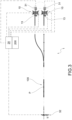
- said detection means comprise at least one laser triangulation profilometer 31 which:
- the expression “arranged substantially diametrically opposite to the distributor 13 relative to the spool 11" means any position in the half-plane opposite to the one in which the distributor is located, the two half-planes being identified by the diametrical plane PD passing through the instantaneous winding point W and the rotation axis Y of the spool.
- the profilometer 31 is oriented with respect to said spool 11 so as to scan the surface of the coil in a position angularly displaced around the rotation axis Y with respect to said instantaneous winding point W of the rolled product.
- the profile of the surface of the coil in formation is detected at a given diametral section instead of detecting the winding angle on the spool.
- the detection may not be carried out at the instantaneous winding point W (a zone in which the rolled product P is subject to vibration), but instead may be carried out at another portion of the coil downstream of such a point W, a zone in which the rolled product is much less subject to vibration because it is already stably wound on the spool.
- the winding can be implemented and managed more easily and reliably.
- the orientation position of said profilometer 31 with respect to said spool for scanning the coil surface is angularly displaced around the rotation axis Y by an angle comprised between 75° and 105° with respect to said instantaneous winding point of the rolled product. More preferably, said angle ⁇ is about 90° (as shown in figure 6 ).
- the laser triangulation profilometer 31 as well as its principle of operation, are known to a person skilled in the art and will not be described in more detail except to point out that the profilometer 31 comprises:
- the laser beam emitted by the emitter 310 illuminates the target (the surface of the coil).
- the light reflected from the surface is detected by the sensor, creating a profile of the illuminated surface.
- the profilometer 31 emits a laser beam LB which illuminates the entire height H1 of the spool and thus of the coil in formation.
- a laser profilometer can be provided if the height of the spool cannot be illuminated in its entirety by a single laser beam. In this case, the height of the spool is divided into several parts, each of which is covered by a laser profilometer.
- said at least one 31 laser triangulation profilometer is suitable for detecting for each turn:
- the laser profilometer 31 it is thus possible to determine the spatial coordinates Xc and Yc of each turn in a coordinate system having the rotation axis Y as its y-axis and the diametrical axis of the spool lying on the reference plane RP and passing through the zone of the spool/coil scanned by the profilometer 31 as its x-axis.
- the profilometer can be used to detect the profile of the surface of the wound coil for the purpose of detecting, as an alternative to or in addition to the position of the turns, winding imperfections, substantially consisting of any empty gaps between the coils.
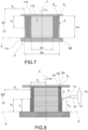
- said at least one laser triangulation profilometer 31 can be electronically operated so as to scan inside a scanning window F having a height H less than the height H1 of the spool 11 along the rotation axis Y.
- such a scanning window F is generated by operating at the software level on the sensor, limiting the reading of the sensor to a given reading height H.
- the method operates on the sensor 311 of the profilometer 31 by limiting the reading of the sensor itself in the window F also to a given reading depth D, intended in the radial direction.
- such a scanning window F is moved by software along the height H1 of the spool parallel to the rotation axis Y so that the scanning window can follow the coil being forming at every added turn; the sensor 311 remains fixed. In this manner, vibrations on the profilometer 31 and mechanical complications in moving it are avoided.
- said at least one laser triangulation profilometer 31 is configured to update the position of the scanning window with a delay comprised between 10 and 50 ms.
- said at least one laser triangulation profilometer 31 has a minimum scanning frequency of 300 Hz.
- the winding system 1 further comprises a processing and calculation unit 200 which is configured to adjust in feedback - on the basis of the surface profile of the coil of rolled product detected by the profilometer 31 at every added turn - the translation speed Vt of the distributor 13 so as to minimize the difference between an actual operating parameter calculated on the basis of the profile of the coil in formation detected by said profilometer 31 and the same operating parameter calculated on the basis of theoretical data related to a predetermined ideal winding of the coil.
- a processing and calculation unit 200 which is configured to adjust in feedback - on the basis of the surface profile of the coil of rolled product detected by the profilometer 31 at every added turn - the translation speed Vt of the distributor 13 so as to minimize the difference between an actual operating parameter calculated on the basis of the profile of the coil in formation detected by said profilometer 31 and the same operating parameter calculated on the basis of theoretical data related to a predetermined ideal winding of the coil.
- the rolled products winding system 1 according to the invention thus allows achieving the correct winding of a coil easily and reliably.
- the rolled product winding system 1 according to the invention is easy to make or implement.
- said actual operating parameter calculated on the basis of the profile of the coil in formation detected by said profilometer 31 at every added turn, is:
- the actual height Hr of the n-th layer of the coil in formation at each further added turn corresponds to the position in height Yc of the last added turn.
- the real growth rate Vgr of each n-th layer at every further added turn is defined as the linear speed with which the height H1/Yc of the n-th layer grows parallel to the rotation axis Y.
- Figure 11 shows a graph illustrating the height position of each turn of an n-th layer over time; in such an example, the trend is linear; the growth rate is defined by the angular coefficient m of the line.
- the processing and calculation unit 200 calculates the real growth rate Vgr by relating the position Yc of each turn over time, consequently generating graphs as shown in figure 11 .
- the real growth rate Vgr of each n-th layer changes direction according to the direction of growth of the layer (upward or downward) .
- said predetermined winding programme is aimed at feedback adjusting the translation speed Vt of the distributor so that the actual height Hr is substantially equivalent to the theoretical height Ht of the n-th layer of the coil in formation at every further added turn.
- the turns are in contact with each other; therefore, there are no spaces between the turns.
- the theoretical height Ht of the n-th layer (and in general of the coil) can then be calculated as the sum of the diameters of the plurality of wound turns; in this operation, reference must be made to the diameters of the turns along a same line parallel to the rotation axis Y.
- the theoretical height Ht can thus be calculated based on the rolled product diameter values previously made available to the processing and calculation unit 200, as a function of the spool height.
- the rolled material P has a variable cross-section area because it is subject to small diameter variations dictated by the rolling process placed upstream (wear, etc.). Therefore, the diameter of the rolled material is not constant. Such a variability affects the formation of the coil.
- the diameter of the rolled product which is progressively fed to the winding system 1 can be measured in real time.
- said predetermined winding programme is aimed at feedback adjusting the translation speed Vt of the distributor so that the travel speed of the distributor is substantially equivalent to the actual growth rate Vgr of each n-th layer at every further added coil to prevent the distributor 13 from being ahead and/or behind the coil in formation thus avoiding producing defects on the coil.
- the aforesaid detection means further comprise an online meter 32 of the diameter of the rolled product.
- the meter 32 is suitable to continuously measure the diameter of the rolled product D and is placed upstream of the distributor 13 along the feed line 100 of the rolled product P.
- the processing and calculation unit 200 is configured to use the measurements of the diameter of the rolled product made by the meter 32 as values of the diameter of the rolled product.
- said processing and calculation unit 200 is configured to correlate the respective detection time to each diameter measurement.
- said processing and calculation unit 200 is configured to correlate the respective detection time to each diameter measurement.
- the aforesaid predetermined reference operating parameters storable by said control and command unit 20 consist of:
- the processing and calculation unit 200 can calculate the rotational speed Vr of the spool 11 and the translation speed Vt of the distributor 13, as will be described in detail below.
- an online meter 32 of the diameter of the rolled product may not be provided.
- the processing and calculation unit 200 is configured to use preset values, storable by said control and command unit 20 as values of the diameter of the rolled product.
- the aforesaid predetermined reference operating parameters storable by said control and command unit 20 comprise at least:
- the processing and calculation unit 200 can calculate the rotational speed Vr of the spool 11 and the translation speed Vt of the distributor 13, as will be described in detail below.
- the processing and calculation unit 200 is configured to initialize the translation speed Vt of the distributor at a theoretical translation speed Vtt, which is calculated as a function of:
- Vtt H1/Tfl.
- Ns H1 / ⁇ P.
- the translation speed of the distributor Vt is feedback adjusted according to two options.
- Option 1 adjusting Vt so that the actual height Hr is substantially equivalent to the theoretical height Ht of the n-th layer of the coil in formation at every further added turn.
- the adjustment criterion is as follows:
- the rolled product must be wound on the spool with an orientation substantially orthogonal to the rotation axis Y of the spool, within a predetermined tolerance.
- Such a condition occurs when the product supply output 14 of the distributor 13 is aligned with the instantaneous winding point W. Such a condition is verified if Hr substantially coincides with Ht.
- Option 2 adjusting the translation speed of the distributor is substantially equivalent to the actual growth rate Vgr of each n-th layer at every further added turn.
- some calculation parameters can be modified by introducing corrective factors K, which allow the coil winding characteristics to be varied to specific requirements.
- corrective factors K which allow the coil winding characteristics to be varied to specific requirements.
- the number of turns which stay within the coil height can be changed with corrective parameters K.
- the translation speed Vt of the distributor can also be changed with corrective parameters K from the theoretical one to achieve specific coil winding effects by keeping the distributor further retracted from the last wound turn.
- the processing and calculation unit 200 is configured to adjust the rotation speed Vr of the spool as a function of:
- the method according to the invention comprises the following operating steps:
- said actual operating parameter calculated on the basis of the profile of the coil in formation detected by said profilometer 31 at every added turn, is:
- the translation speed Vt of the distributor can be feedback adjusted so that the actual height Hr is substantially equivalent to the theoretical height Ht of the n-th layer of the coil in formation at every additional turn added.
- the theoretical height Ht is calculated based on the rolled product diameter values previously made available to the processing and calculation unit 200, as a function of spool height.
- the travel speed Vt of the distributor can be feedback adjusted so that the translation speed of the distributor Vt is substantially equivalent to the real growth rate Vgr of each n-th layer at every further added turn.
- said laser triangulation profilometer 31 is suitable to detect for each turn the radial distance from the rotation axis Y of the spool and the height position along such a rotation axis Y.
- the value of rolled product diameter ⁇ P can be obtained from continuous measurements on the rolled product P by an online meter 32 placed upstream of the distributor 13 along the rolled product feed line. Each diameter measurement is related to its respective detection time.
- the retroactive adjustment of the translation speed Vt of the distributor uses predetermined reference operating parameters storable by said control and command unit 20 which consist of:
- the value of the diameter of the rolled product ⁇ P is a preset nominal value.
- the retroactive adjustment of the translation speed Vt of the distributor uses predetermined reference operating parameters storable by said control and command unit 20 which consist of:
- the translation speed Vt of the distributor is initialized at a theoretical translation speed, which is calculated as a function of:
- the rotation speed of the spool is adjusted as a function of:
- the invention provides numerous advantages, some of which have already been described.
- the rolled products winding system 1 according to the invention thus allows achieving the correct winding of a coil easily and reliably.
- the rolled product winding system 1 according to the invention is easy to make or implement.
Landscapes
- Engineering & Computer Science (AREA)
- Mechanical Engineering (AREA)
- Physics & Mathematics (AREA)
- General Physics & Mathematics (AREA)
- Winding, Rewinding, Material Storage Devices (AREA)
- Winding Filamentary Materials (AREA)
Applications Claiming Priority (1)
| Application Number | Priority Date | Filing Date | Title |
|---|---|---|---|
| IT202300015246 | 2023-07-20 |
Publications (2)
| Publication Number | Publication Date |
|---|---|
| EP4494774A1 true EP4494774A1 (de) | 2025-01-22 |
| EP4494774B1 EP4494774B1 (de) | 2026-04-29 |
Family
ID=88291097
Family Applications (1)
| Application Number | Title | Priority Date | Filing Date |
|---|---|---|---|
| EP24187808.1A Active EP4494774B1 (de) | 2023-07-20 | 2024-07-10 | Wickelsystem und -verfahren für gewalzte produkte |
Country Status (5)
| Country | Link |
|---|---|
| US (1) | US20250026606A1 (de) |
| EP (1) | EP4494774B1 (de) |
| JP (1) | JP2025015517A (de) |
| KR (1) | KR20250015953A (de) |
| CN (1) | CN119327870A (de) |
Citations (5)
| Publication number | Priority date | Publication date | Assignee | Title |
|---|---|---|---|---|
| GB2221227A (en) * | 1988-06-16 | 1990-01-31 | Ceat Cavi Spa | Automatic winder: transverse control |
| US7370823B2 (en) * | 2006-04-20 | 2008-05-13 | Maschinenfabrik Niehoff Gmbh & Co. Kg | Method and device for laying of elongated winding material |
| EP3362390B1 (de) | 2015-10-16 | 2019-09-04 | Danieli Automation SPA | Verwaltungsverfahren für eine wicklervorrichtung und entsprechendes vorrichtung |
| CA3109332A1 (en) * | 2018-07-10 | 2020-01-16 | Stimline As | A winding apparatus |
| US20220185638A1 (en) * | 2019-08-02 | 2022-06-16 | Liebherr-Components Biberach Gmbh | Cable winch and hoisting device having such a cable winch |
-
2024
- 2024-07-10 EP EP24187808.1A patent/EP4494774B1/de active Active
- 2024-07-12 US US18/771,975 patent/US20250026606A1/en active Pending
- 2024-07-18 KR KR1020240094898A patent/KR20250015953A/ko active Pending
- 2024-07-19 JP JP2024115819A patent/JP2025015517A/ja active Pending
- 2024-07-22 CN CN202410980372.9A patent/CN119327870A/zh active Pending
Patent Citations (5)
| Publication number | Priority date | Publication date | Assignee | Title |
|---|---|---|---|---|
| GB2221227A (en) * | 1988-06-16 | 1990-01-31 | Ceat Cavi Spa | Automatic winder: transverse control |
| US7370823B2 (en) * | 2006-04-20 | 2008-05-13 | Maschinenfabrik Niehoff Gmbh & Co. Kg | Method and device for laying of elongated winding material |
| EP3362390B1 (de) | 2015-10-16 | 2019-09-04 | Danieli Automation SPA | Verwaltungsverfahren für eine wicklervorrichtung und entsprechendes vorrichtung |
| CA3109332A1 (en) * | 2018-07-10 | 2020-01-16 | Stimline As | A winding apparatus |
| US20220185638A1 (en) * | 2019-08-02 | 2022-06-16 | Liebherr-Components Biberach Gmbh | Cable winch and hoisting device having such a cable winch |
Also Published As
| Publication number | Publication date |
|---|---|
| KR20250015953A (ko) | 2025-02-03 |
| EP4494774B1 (de) | 2026-04-29 |
| US20250026606A1 (en) | 2025-01-23 |
| JP2025015517A (ja) | 2025-01-30 |
| CN119327870A (zh) | 2025-01-21 |
Similar Documents
| Publication | Publication Date | Title |
|---|---|---|
| JP6670931B2 (ja) | 巻き取り装置の管理方法、および対応するデバイス | |
| JP5952269B2 (ja) | 被コートねじ接合の幾何学的パラメーターの測定方法 | |
| CA2109766C (en) | Uniform width payout hole | |
| US20110239719A1 (en) | Method and apparatus for production of helical springs by spring winding | |
| US5410786A (en) | Process and arrangement for the warping of threads onto a drum having a conical surface | |
| EP4494774B1 (de) | Wickelsystem und -verfahren für gewalzte produkte | |
| EP3021996B1 (de) | Federherstellungsvorrichtung, verfahren zur herstellung einer schraubenfeder und entsprechendes computerprogramm | |
| US5480342A (en) | Centerless grinding machine control system | |
| US4483496A (en) | Method of winding filamentary goods, in particular cables | |
| US5930734A (en) | Method and apparatus for measuring the thickness of non-circular elongated workpieces | |
| US5477715A (en) | Adaptive spring winding device and method | |
| CN102400256B (zh) | 分条整经机和用于运行分条整经机的方法 | |
| US5758395A (en) | Controlling feed in a thread warping process and machine | |
| EP3774104B1 (de) | System zum legen von coils eines warmgewalzten produkts und verfahren zum legen von coils | |
| CA3109332C (en) | A winding apparatus | |
| US9463948B2 (en) | Control methods for producing precision coils | |
| GB2310154A (en) | Cylindrical grinding | |
| KR20220038451A (ko) | 에지 빌드-업 측정 | |
| US6297882B1 (en) | Method and apparatus for measuring paper color | |
| JPH06258034A (ja) | 管体の外径測定方法及びその装置 | |
| WO2025243337A1 (en) | Apparatus and method for measuring a ribbed wire | |
| JPH0339948B2 (de) | ||
| JPH0523733A (ja) | スパイラル鋼管の自動外周制御方法 | |
| JPH0382906A (ja) | 整列巻乱れ検出方法 | |
| NL9002711A (nl) | Werkwijze en inrichting voor het regelen van de wanddikte van een door een folieblaasextrusie-inrichting geextrudeerde buisfolie. |
Legal Events
| Date | Code | Title | Description |
|---|---|---|---|
| PUAI | Public reference made under article 153(3) epc to a published international application that has entered the european phase |
Free format text: ORIGINAL CODE: 0009012 |
|
| STAA | Information on the status of an ep patent application or granted ep patent |
Free format text: STATUS: THE APPLICATION HAS BEEN PUBLISHED |
|
| AK | Designated contracting states |
Kind code of ref document: A1 Designated state(s): AL AT BE BG CH CY CZ DE DK EE ES FI FR GB GR HR HU IE IS IT LI LT LU LV MC ME MK MT NL NO PL PT RO RS SE SI SK SM TR |
|
| STAA | Information on the status of an ep patent application or granted ep patent |
Free format text: STATUS: REQUEST FOR EXAMINATION WAS MADE |
|
| 17P | Request for examination filed |
Effective date: 20250711 |
|
| GRAP | Despatch of communication of intention to grant a patent |
Free format text: ORIGINAL CODE: EPIDOSNIGR1 |
|
| STAA | Information on the status of an ep patent application or granted ep patent |
Free format text: STATUS: GRANT OF PATENT IS INTENDED |
|
| RIC1 | Information provided on ipc code assigned before grant |
Ipc: B21C 47/00 20060101AFI20251107BHEP Ipc: B21C 47/04 20060101ALI20251107BHEP Ipc: B21C 47/12 20060101ALI20251107BHEP Ipc: B21C 47/34 20060101ALI20251107BHEP |
|
| INTG | Intention to grant announced |
Effective date: 20251128 |
|
| GRAS | Grant fee paid |
Free format text: ORIGINAL CODE: EPIDOSNIGR3 |
|
| GRAA | (expected) grant |
Free format text: ORIGINAL CODE: 0009210 |
|
| STAA | Information on the status of an ep patent application or granted ep patent |
Free format text: STATUS: THE PATENT HAS BEEN GRANTED |
|
| AK | Designated contracting states |
Kind code of ref document: B1 Designated state(s): AL AT BE BG CH CY CZ DE DK EE ES FI FR GB GR HR HU IE IS IT LI LT LU LV MC ME MK MT NL NO PL PT RO RS SE SI SK SM TR |
|
| REG | Reference to a national code |
Ref country code: CH Ref legal event code: F10 Free format text: ST27 STATUS EVENT CODE: U-0-0-F10-F00 (AS PROVIDED BY THE NATIONAL OFFICE) Effective date: 20260429 Ref country code: GB Ref legal event code: FG4D |