EP4494751A1 - Statischer mischereinsatz und statischer mischer - Google Patents
Statischer mischereinsatz und statischer mischer Download PDFInfo
- Publication number
- EP4494751A1 EP4494751A1 EP23186652.6A EP23186652A EP4494751A1 EP 4494751 A1 EP4494751 A1 EP 4494751A1 EP 23186652 A EP23186652 A EP 23186652A EP 4494751 A1 EP4494751 A1 EP 4494751A1
- Authority
- EP
- European Patent Office
- Prior art keywords
- static mixer
- mixing
- mixing structure
- mixer insert
- width
- Prior art date
- Legal status (The legal status is an assumption and is not a legal conclusion. Google has not performed a legal analysis and makes no representation as to the accuracy of the status listed.)
- Withdrawn
Links
Images


Classifications
-
- B—PERFORMING OPERATIONS; TRANSPORTING
- B01—PHYSICAL OR CHEMICAL PROCESSES OR APPARATUS IN GENERAL
- B01F—MIXING, e.g. DISSOLVING, EMULSIFYING OR DISPERSING
- B01F23/00—Mixing according to the phases to be mixed, e.g. dispersing or emulsifying
- B01F23/40—Mixing liquids with liquids; Emulsifying
- B01F23/47—Mixing liquids with liquids; Emulsifying involving high-viscosity liquids, e.g. asphalt
-
- B—PERFORMING OPERATIONS; TRANSPORTING
- B01—PHYSICAL OR CHEMICAL PROCESSES OR APPARATUS IN GENERAL
- B01F—MIXING, e.g. DISSOLVING, EMULSIFYING OR DISPERSING
- B01F25/00—Flow mixers; Mixers for falling materials, e.g. solid particles
- B01F25/40—Static mixers
- B01F25/42—Static mixers in which the mixing is affected by moving the components jointly in changing directions, e.g. in tubes provided with baffles or obstructions
- B01F25/43—Mixing tubes, e.g. wherein the material is moved in a radial or partly reversed direction
- B01F25/431—Straight mixing tubes with baffles or obstructions that do not cause substantial pressure drop; Baffles therefor
- B01F25/43197—Straight mixing tubes with baffles or obstructions that do not cause substantial pressure drop; Baffles therefor characterised by the mounting of the baffles or obstructions
- B01F25/431974—Support members, e.g. tubular collars, with projecting baffles fitted inside the mixing tube or adjacent to the inner wall
-
- B—PERFORMING OPERATIONS; TRANSPORTING
- B01—PHYSICAL OR CHEMICAL PROCESSES OR APPARATUS IN GENERAL
- B01F—MIXING, e.g. DISSOLVING, EMULSIFYING OR DISPERSING
- B01F25/00—Flow mixers; Mixers for falling materials, e.g. solid particles
- B01F25/40—Static mixers
- B01F25/42—Static mixers in which the mixing is affected by moving the components jointly in changing directions, e.g. in tubes provided with baffles or obstructions
- B01F25/43—Mixing tubes, e.g. wherein the material is moved in a radial or partly reversed direction
- B01F25/432—Mixing tubes, e.g. wherein the material is moved in a radial or partly reversed direction with means for dividing the material flow into separate sub-flows and for repositioning and recombining these sub-flows; Cross-mixing, e.g. conducting the outer layer of the material nearer to the axis of the tube or vice-versa
- B01F25/4321—Mixing tubes, e.g. wherein the material is moved in a radial or partly reversed direction with means for dividing the material flow into separate sub-flows and for repositioning and recombining these sub-flows; Cross-mixing, e.g. conducting the outer layer of the material nearer to the axis of the tube or vice-versa the subflows consisting of at least two flat layers which are recombined, e.g. using means having restriction or expansion zones
Definitions
- the present invention relates to a static mixer insert and a static mixer with such a static mixer insert.
- static mixer inserts having a mixing structure with a therein integrated support structure are provided to form compact and robust static mixer inserts and corresponding static mixers.
- Such configurations enable quite compact static mixers with good mixing characteristics.
- the compactness and mixing characteristics of such prior art configurations are limited due to negative interaction effects between the structural integrity of such static mixer inserts and their mixing characteristics.
- the smaller static mixer inserts are the larger the support structures generally have to be in a relative sense. This results in less free mixing space within the mixing structure and, thus, in deteriorated mixing characteristics.
- a static mixer insert for mixing two viscous components within a mixing tube of a static mixer comprises a mixing structure defining a mixing area with a plurality of consecutive mixing chambers arranged along a longitudinal axis of the mixing structure when disposed within said mixing tube, and two longitudinally extending support bars laterally connected outside to the mixing structure.
- Said two support bars outside the mixing structure allow an improved structural integrity and robustness for the static mixer insert without limiting the free cross-section of the mixing structure.
- static mixer inserts with smaller overall dimensions and/or an improved mixing structure can be formed.
- the mixing structure is formed of various parts connected to each other in such a way that they form a single interconnected part.
- the parts of the mixing structure form an integrated part having already a certain basic stability, which is then supplemented by the two support bars.
- the support bars are not formed by the parts of the mixing structure but by separate elements connected to the parts of the mixing structure.
- the mixing structure and the support bars are formed integrally, in particular via an injection-moulding process. This means that they are formed as one piece.
- the mixing structure has a substantially rectangular cross-section, in particular with a ratio of its width to its depth of 0.7 to 1.3, preferably of 1.0.
- the mixing structure has a width of 1.0mm to 4.0mm, in particular of 1.0mm to 2.5mm and preferably of 1.7mm to 1.9mm, especially of 1.8mm.
- Such a configuration is very compact and is suitable for very accurate dispensing processes of small amounts of component-mixtures. These very small dimensions for the mixing structure are only achievable with the support bars as defined above.
- the mixing structure comprises a first set of separation walls provided in a first plane along the longitudinal axis of the mixing structure and connecting the two support bars with each other.
- the mixing structure comprises a second set of separation walls provided in a second plane along the longitudinal axis and oriented perpendicular with respect to the first plane.
- Each separation wall of said second set of separation walls connects two separations walls of the first set of separations walls successive along the longitudinal axis of the mixing structure, to each other.
- said separation walls define passage windows within said first plane or said second plane.
- a ratio of the height to the width of each of said passage windows is in particular in the range of 0.5 to 1.0.
- the mixing structure comprises a deflection plate at the upstream or downstream end of each of said passage windows.
- Each of said deflection plates is tilted with respect to the longitudinal axis of the mixing structure, in particular by an angle in the range of 60° to 120°, for example by an angle of 90°.
- Such deflection plates result in beneficial flow characteristics of the components along the mixing structure and, thus, in good mixing characteristics.
- each of the two support bars has an at least partially, in particular fully polygonal cross-section, for example a preferably equilateral triangular, quadrangular, pentagonal, hexagonal or octagonal cross-section, an at least partially, in particular fully, oval cross-section and/or an at least partially, in particular fully, circular cross-section.
- each support bar comprises a tapered portion at one of its longitudinal ends, in particular at its downstream end.
- Said cross-sections allow very robust but quite compact configurations for the support bars.
- Said tapered portions simplify an introduction of the static mixer insert in a corresponding mixing tube.
- the ratio of the thickness to the width of each support bar is in the range of 0.4 to 0.7.
- This configuration allows a very compact but still robust overall static mixer insert.
- the ratio of the width of each of the support bars to the width of the mixing structure is in the range of 0.2 to 0.5.
- This configuration allows a very compact but still robust overall static mixer insert.
- the mixing structure comprises at least one, in particular multiple, of the following special elements for optimizing the component flows and/or the mixing of the viscous components when traveling along the mixing structure: guiding bars tilted with respect to the longitudinal axis of the mixing structure, in particular by an angle in the range of 45° to 90°, for example by an angle of 60°; exchange elements formed of a first a deflection plate at a downstream end of a passage window, a second deflection plate at an upstream end of said passage window and the separation wall connecting said two deflection plates to each other; tilted separation aid plates connected to a downstream end or to an upstream end of one of the separation walls.
- said guiding bars have a width of no more than 25% of the width of the mixing structure and/or guiding bars are provided along a separation wall of the above described first set of separation walls or connected at one end to a separation wall of the above described second set of separation walls and at its other end to one of the support bars.
- the separation wall connecting the two deflection plates of one exchange element to each other has a width corresponding to the width of the mixing structure at the location of said separation wall, or a width, in particular substantially, smaller than the width of the mixing structure at the location of said separation wall.
- parts, in particular all parts, of the mixing structure have a thickness in the range of 0.10mm to 0.30mm, in particular of 0.15mm.
- a static mixer for mixing two viscous components comprises a longitudinal mixing tube and one of the above described static mixer inserts provided within said mixing tube.
- Said mixing tube allows the final usage of the above described static mixer inserts for a mixing and dispensing process.
- the static mixer insert is fixed via press-fit and/or ultrasonic welding to the mixing tube.
- the press-fit configuration is very simple, while the ultrasonic welding configuration is very robust.
- the mixing tube comprises a longitudinally extending central opening receiving the mixing structure of the static mixer insert, and two longitudinally extending recesses formed along the central opening, each receiving one of the two support bars.
- the static mixer insert comprises a head connected to the mixing structure and to the support bars.
- Said head comprises a flat disc portion extending perpendicular with respect to the longitudinal axis of the mixing structure and two inlets, one for each viscous component, oriented in parallel but shifted with respect to the longitudinal axis of the mixing structure.
- the mixing structure is connected to said head such that a first separation wall of the mixing structure is connected to said head and lies within a common extension plane defined by the two inlets, or is oriented perpendicular with respect to said common extension plane.
- the described parallel orientation of the first separation wall results in a direct mixing of the two components when entering the mixing structure and, thus in improved mixing characteristics.
- the described perpendicular orientation of the first separation wall results in a reliable prevention of components flowing from one of the inlets via the other inlet into the other component chamber of the dispensing device connected to the static mixer.
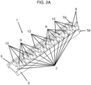
- an exemplary static mixer 100 in accordance with the present invention comprises a static mixer insert 1 and a mixing tube 50.
- Said static mixer insert 1 comprises a mixing structure 3 extending longitudinally along a longitudinal axis LA of the mixing structure 3.
- the mixing structure 3 is received by a longitudinal central passageway 52 formed by the mixing tube 50.
- the static mixer insert 1 comprises two longitudinally extending support bars 5 (see in particular the following figures), each received by a longitudinal recess 54 along the central passageway 52 of the mixing tube 50.
- the present static mixer insert 1 is provided with a head 21 comprising a flat disc portion 23 and two inserts 25 oriented in parallel with the longitudinal axis LA of the mixing structure 3.
- Said head 21 is provided for a fluidical coupling of the mixing structure 3 with outlets of a dispensing device (not illustrated) comprising two chambers, each filled with one of the two viscous components, which are to be mixed with each other prior to application thereof at a desired area.
- a dispensing device (not illustrated) comprising two chambers, each filled with one of the two viscous components, which are to be mixed with each other prior to application thereof at a desired area.
- component as used herein includes both of pure materials and composite material.
- the disc portion 23 of the head 21 is ultrasonic-welded to a coupling ring 60 provided around a cover portion 58 of the mixing tube 50 to provide a further fixation of the static mixer insert 1 to the mixing housing 50 in addition to a press-fit fixation formed between the longitudinal support bars 5 of the static mixer insert 1 and the recesses 54 of the mixing tube 50.
- the mixing tube 50 is provided with a coupling portion 56 for connecting a dispensing tip (not illustrated) thereto.
- a dispensing tip could also be integrated directly into the mixing tube 50.
- the mixing structure 3 is connected to said head 21 in an orientation resulting in that a first separation wall (described further below; 7) of the mixing structure 3 is oriented perpendicular with respect to a common extension plane of the two inlets 25 (substantially corresponding to the sectional plane of FIG. 1 ).
- a first separation wall (described further below; 7) of the mixing structure 3 is oriented perpendicular with respect to a common extension plane of the two inlets 25 (substantially corresponding to the sectional plane of FIG. 1 ).
- said first separation wall 7 can lie within said common extension plane resulting in a direct mixing of the components from the two inlets 25.
- a static mixer insert 1 according to a first embodiment of the present invention comprises a mixing structure 3 formed of various flat elements 7, 9 and 13, and therewith integrally formed, for example via an injection-moulding process, two support bars 5 with semi-circular cross-sections.
- the mixing structure 3 comprises a first set of separation walls 7 connecting the two support bars 5 to each other, a second set of separation walls 9 connecting successive separation walls 7 of the first set of separation wall 7 to each other, and deflection plates 13 coupled to the separation walls 7 and 8.
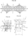
- the separation walls 7 of the first set of separation walls 7 lie within a first plane along the longitudinal axis LA of the mixing structure 3 (parallel to the image plane of FIGS. 2B and 2C ).
- the separation walls 9 of the second set of separation walls 9 lie within a second plane along the longitudinal axis LA of the mixing structure 3 but in perpendicular with respect to the first plane of the separation walls 7 of the first set of separation walls 7 (parallel to the image plane of FIG. 2E ).
- the deflection plates 13 are oriented substantially perpendicular with respect to both of the first plane of the separation walls 7 of the first set of separation walls 7 and the second plane of the separation walls 9 of the second set of separation walls 9 (i.e. parallel to the image plane one FIGS. 2D and 2F ).
- Said passage windows 11 are formed with an aspect ratio of 0.5 to 1.0.
- the deflection plates 13 are provided on an upstream side of each of said passage windows 11 and oriented perpendicular to the longitudinal axis LA of the mixing structure 3.
- said deflection plates 13 can be position also on a downstream side and/or can be tilted with respect to the longitudinal axis LA by an angle ⁇ (see FIG. 2C ) in the range of 60° to 120°.
- the parts 7, 9 and 13 of the mixing structure are dimensioned such that the mixing structure 3 has a substantially rectangular cross-section with an aspect ratio, i.e. with a ratio of its width S to its depth T of 0.7 to 1.3, in particular of 1.0 (see FIG. 2D ).
- the provided support bars 5 allow mixing structures 3 with a width S of 1.0mm to 4.0mm and in particular of 1.8mm.
- each support bar 5 can be provided with a tapered portion 5a for facilitating an insertion operation into a corresponding mixing tube 50 for forming a static mixer 100 in accordance with the present invention (see for example FIG. 2B ).
- the ratio of the thickness D to the width C of each of the support bars 5 is in the range of 0.4 to 0.7 while the ratio of the width C of each of the support bars 5 to the width S of the mixing structure is in the range of 0.2 to 0.5, to ensure a preferable structural stability.
- a separation wall 9 from the second set of separation walls 9 can form the first separation wall of the mixing structure 3.
- sets of two connected separation walls 7 and 9 with a thereto connected deflection plate 13 can be considered as one mixing element, wherein several, like for example twelve as in the illustrated embodiment or even more like for example twenty-four, of these mixing elements can form the mixing structure 3.
- mixing elements can be supplemented by one or multiple of special elements 15, 17 and/or 19 for optimizing flow-guiding and mixing characteristics of the mixing structure 3.
- special elements 15, 17 and 19 Three examples of such special elements 15, 17 and 19 are described in the following with respect to Figures 4A to 10B .
- Said special elements 15, 17 and 19 can be combined with the mixing elements and/or each other in any desired manner.
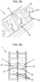
- a first example of such special elements are guiding bars 15 (see FIGS. 4A to 6B ) which are provided with respect to the longitudinal axis LA of the mixing structure in a tilted manner, in particular by an angle ⁇ in the range of 45° to 90°, like for example by an angle of 60°.
- Said guiding bars are provided in particular with a width W of no more than 25% of the width S of the mixing structure 3.
- Such guiding bars 15 can be provided along one separation wall 7 of the first set of separation walls 7, as illustrated in FIGS. 4A and 4B .
- the guiding bars 15 can connect a separation wall 9 of the second set of separation walls 9 with one of the two support bars 5, as illustrated in FIGS. 5A and 5B .
- This second kind of guiding bars 15 is preferably positioned such that in an assembled state of the static mixer insert 1 with a corresponding mixing tube 50, these guiding bars 50 run along the inner surface of the mixing tube 50.
- Such guiding bars 15 allow to separate component flows from the separation walls 7 and 9 and/or from the inner surface of the mixing tube 50 for improved flow-guiding and mixing characteristics of the finally formed static mixer 100.
- guiding bars 15 of both above described implementations can be combined with each other, as illustrated for example in FIGS. 6A and 6B . be.
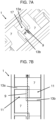
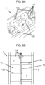
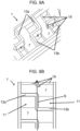
- a second example of such special elements are exchange elements 17 formed of a first a deflection plate 13a at a downstream end of a passage window 11, a second deflection plate 13b at an upstream end of said passage window 11 and a separation wall 9 connecting said two deflection plates 13a and 13b to each other.
- the corresponding separation wall 9 can have a width E, preferably substantially, smaller than the width S of the mixing structure 3 at the location of said separation wall 9.
- the corresponding separation wall 9 can have a width E corresponding to the width S of the mixing structure 3 at the location of said separation wall 9, such that only a circulation but no splitting/mixing of the component flows occurs within the exchange element 17 (see FIGS. 8A and 8B ).
- the exchange elements 17 can be configured to generate both of a clockwise circulation (see FIGS. 8A and 8B ) and a counter-clockwise circulation (see FIGS. 9A and 9B ).
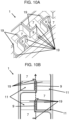
- a third example of such special elements are tilted separation aid plates 19 connected to downstream and/or upstream ends of the separation walls 7 and/or 9, as can be seen in particular in FIGS. 10A and 10B .
- These separation aid plates 19 serve to optimize the separation and combination of the component flows for an improved mixing characteristic.
- the described special elements 15, 17 and 19 can be combined with each other and with the above described standard mixing elements in any desired number or combination.
- the separation aid plates 19 can be combined with the above described guiding plates 15, with the above described exchange elements 17 and/or with further separation aid plates 19 freely. The same holds for other combinations.
- various parts, in particular all parts, of the mixing structure 3 are provided with a thickness in the range of 0.10mm to 0.30mm, in particular of 0.15mm
Landscapes
- Chemical & Material Sciences (AREA)
- Chemical Kinetics & Catalysis (AREA)
- Dispersion Chemistry (AREA)
- Engineering & Computer Science (AREA)
- Civil Engineering (AREA)
- Structural Engineering (AREA)
Priority Applications (7)
| Application Number | Priority Date | Filing Date | Title |
|---|---|---|---|
| EP23186652.6A EP4494751A1 (de) | 2023-07-20 | 2023-07-20 | Statischer mischereinsatz und statischer mischer |
| PCT/EP2024/056702 WO2024189099A1 (en) | 2023-03-13 | 2024-03-13 | Static mixer insert, static mixer and dispensing system |
| EP24710130.6A EP4646289A1 (de) | 2023-03-13 | 2024-03-13 | Statischer mischereinsatz, statischer mischer und abgabesystem |
| CN202480018500.XA CN120882477A (zh) | 2023-03-13 | 2024-03-13 | 静态混合器插入件、静态混合器和分配系统 |
| KR1020257033963A KR20250161612A (ko) | 2023-03-13 | 2024-03-13 | 정적 믹서 인서트, 정적 믹서 및 디스펜싱 시스템 |
| CN202480044662.0A CN121443382A (zh) | 2023-07-20 | 2024-06-12 | 静态混合器插入件、静态混合器以及施配系统 |
| PCT/EP2024/066261 WO2025016628A1 (en) | 2023-07-20 | 2024-06-12 | Static mixer insert, static mixer and dispensing system |
Applications Claiming Priority (1)
| Application Number | Priority Date | Filing Date | Title |
|---|---|---|---|
| EP23186652.6A EP4494751A1 (de) | 2023-07-20 | 2023-07-20 | Statischer mischereinsatz und statischer mischer |
Publications (1)
| Publication Number | Publication Date |
|---|---|
| EP4494751A1 true EP4494751A1 (de) | 2025-01-22 |
Family
ID=87426570
Family Applications (1)
| Application Number | Title | Priority Date | Filing Date |
|---|---|---|---|
| EP23186652.6A Withdrawn EP4494751A1 (de) | 2023-03-13 | 2023-07-20 | Statischer mischereinsatz und statischer mischer |
Country Status (3)
| Country | Link |
|---|---|
| EP (1) | EP4494751A1 (de) |
| CN (1) | CN121443382A (de) |
| WO (1) | WO2025016628A1 (de) |
Citations (4)
| Publication number | Priority date | Publication date | Assignee | Title |
|---|---|---|---|---|
| US4600544A (en) * | 1982-11-29 | 1986-07-15 | Merix Corporation | Packing unit and method of making |
| EP0815929A1 (de) * | 1996-07-05 | 1998-01-07 | Sulzer Chemtech AG | Statischer Mischer |
| US20090073800A1 (en) * | 2006-07-11 | 2009-03-19 | Paradox Holding Company, Llc. | Apparatus and Method for Mixing Fluids at the Surface for Subterranean Treatments |
| US20200171448A1 (en) * | 2017-07-28 | 2020-06-04 | 3lmed GmbH | Mixer having compensation channel and/or reservoir chamber |
Family Cites Families (3)
| Publication number | Priority date | Publication date | Assignee | Title |
|---|---|---|---|---|
| EP1125626B1 (de) * | 2000-02-17 | 2005-11-02 | Sulzer Chemtech AG | Statischer Mischer |
| TWI354577B (en) * | 2004-04-22 | 2011-12-21 | Sulzer Chemtech Ag | A static mixer for a curing mixed product |
| EP2614883B1 (de) * | 2012-01-11 | 2015-04-15 | Sulzer Mixpac AG | Mischelement und statischer Mischer |
-
2023
- 2023-07-20 EP EP23186652.6A patent/EP4494751A1/de not_active Withdrawn
-
2024
- 2024-06-12 CN CN202480044662.0A patent/CN121443382A/zh active Pending
- 2024-06-12 WO PCT/EP2024/066261 patent/WO2025016628A1/en active Pending
Patent Citations (4)
| Publication number | Priority date | Publication date | Assignee | Title |
|---|---|---|---|---|
| US4600544A (en) * | 1982-11-29 | 1986-07-15 | Merix Corporation | Packing unit and method of making |
| EP0815929A1 (de) * | 1996-07-05 | 1998-01-07 | Sulzer Chemtech AG | Statischer Mischer |
| US20090073800A1 (en) * | 2006-07-11 | 2009-03-19 | Paradox Holding Company, Llc. | Apparatus and Method for Mixing Fluids at the Surface for Subterranean Treatments |
| US20200171448A1 (en) * | 2017-07-28 | 2020-06-04 | 3lmed GmbH | Mixer having compensation channel and/or reservoir chamber |
Also Published As
| Publication number | Publication date |
|---|---|
| WO2025016628A1 (en) | 2025-01-23 |
| CN121443382A (zh) | 2026-01-30 |
Similar Documents
| Publication | Publication Date | Title |
|---|---|---|
| US7841765B2 (en) | Static mixer | |
| CN106943909B (zh) | 静态混合器 | |
| KR101968476B1 (ko) | 정적 혼합기를 위한 재구성형 혼합 배플 및 정적 혼합기의 제조 방법 | |
| KR100481930B1 (ko) | 저점성유체용믹서튜브 | |
| US20020118598A1 (en) | Static mixer | |
| US20170341041A1 (en) | Static mixer | |
| US10245566B2 (en) | Static mixer | |
| US20060245299A1 (en) | Tube mixer having a longitudinal built-in body | |
| EP0195450A2 (de) | Gestapelter bewegungsloser Mischer | |
| KR102912985B1 (ko) | 정적 혼합기 | |
| KR20200028996A (ko) | 삼각형 혼합 도관을 갖는 정적 혼합기 | |
| EP2599540A1 (de) | Mischelement für einen statischen Mischer | |
| EP3331635B1 (de) | Eingangsmischungselemente und zugehörige statische mischer und verfahren zum mischen | |
| US20080056065A1 (en) | Static Mixer | |
| KR20190100351A (ko) | 정적 혼합기, 부품의 키트 및 정적 혼합기의 용도 | |
| US20110141844A1 (en) | Static mixer | |
| EP4494751A1 (de) | Statischer mischereinsatz und statischer mischer | |
| DE102018005845B4 (de) | Ultraschallzähler | |
| CA3070150C (en) | Mixer | |
| WO2024189099A1 (en) | Static mixer insert, static mixer and dispensing system | |
| EP4371657A1 (de) | Statischer mischer | |
| WO2002081998A1 (en) | Heat exchanger manifold | |
| DE102017117198A1 (de) | Mischer | |
| WO2020243840A1 (en) | System for wall construction | |
| DE10158651B4 (de) | Statisches Mischelement |
Legal Events
| Date | Code | Title | Description |
|---|---|---|---|
| PUAI | Public reference made under article 153(3) epc to a published international application that has entered the european phase |
Free format text: ORIGINAL CODE: 0009012 |
|
| STAA | Information on the status of an ep patent application or granted ep patent |
Free format text: STATUS: THE APPLICATION HAS BEEN PUBLISHED |
|
| AK | Designated contracting states |
Kind code of ref document: A1 Designated state(s): AL AT BE BG CH CY CZ DE DK EE ES FI FR GB GR HR HU IE IS IT LI LT LU LV MC ME MK MT NL NO PL PT RO RS SE SI SK SM TR |
|
| STAA | Information on the status of an ep patent application or granted ep patent |
Free format text: STATUS: THE APPLICATION IS DEEMED TO BE WITHDRAWN |
|
| 18D | Application deemed to be withdrawn |
Effective date: 20250723 |