EP4494607A2 - Herzklappenprothese mit beutel - Google Patents
Herzklappenprothese mit beutel Download PDFInfo
- Publication number
- EP4494607A2 EP4494607A2 EP24218125.3A EP24218125A EP4494607A2 EP 4494607 A2 EP4494607 A2 EP 4494607A2 EP 24218125 A EP24218125 A EP 24218125A EP 4494607 A2 EP4494607 A2 EP 4494607A2
- Authority
- EP
- European Patent Office
- Prior art keywords
- arms
- frame
- upstream
- valve body
- pouch
- Prior art date
- Legal status (The legal status is an assumption and is not a legal conclusion. Google has not performed a legal analysis and makes no representation as to the accuracy of the status listed.)
- Pending
Links
Images


Classifications
-
- A—HUMAN NECESSITIES
- A61—MEDICAL OR VETERINARY SCIENCE; HYGIENE
- A61F—FILTERS IMPLANTABLE INTO BLOOD VESSELS; PROSTHESES; DEVICES PROVIDING PATENCY TO, OR PREVENTING COLLAPSING OF, TUBULAR STRUCTURES OF THE BODY, e.g. STENTS; ORTHOPAEDIC, NURSING OR CONTRACEPTIVE DEVICES; FOMENTATION; TREATMENT OR PROTECTION OF EYES OR EARS; BANDAGES, DRESSINGS OR ABSORBENT PADS; FIRST-AID KITS
- A61F2/00—Filters implantable into blood vessels; Prostheses, i.e. artificial substitutes or replacements for parts of the body; Appliances for connecting them with the body; Devices providing patency to, or preventing collapsing of, tubular structures of the body, e.g. stents
- A61F2/02—Prostheses implantable into the body
- A61F2/24—Heart valves ; Vascular valves, e.g. venous valves; Heart implants, e.g. passive devices for improving the function of the native valve or the heart muscle; Transmyocardial revascularisation [TMR] devices; Valves implantable in the body
- A61F2/2409—Support rings therefor, e.g. for connecting valves to tissue
-
- A—HUMAN NECESSITIES
- A61—MEDICAL OR VETERINARY SCIENCE; HYGIENE
- A61F—FILTERS IMPLANTABLE INTO BLOOD VESSELS; PROSTHESES; DEVICES PROVIDING PATENCY TO, OR PREVENTING COLLAPSING OF, TUBULAR STRUCTURES OF THE BODY, e.g. STENTS; ORTHOPAEDIC, NURSING OR CONTRACEPTIVE DEVICES; FOMENTATION; TREATMENT OR PROTECTION OF EYES OR EARS; BANDAGES, DRESSINGS OR ABSORBENT PADS; FIRST-AID KITS
- A61F2/00—Filters implantable into blood vessels; Prostheses, i.e. artificial substitutes or replacements for parts of the body; Appliances for connecting them with the body; Devices providing patency to, or preventing collapsing of, tubular structures of the body, e.g. stents
- A61F2/02—Prostheses implantable into the body
- A61F2/24—Heart valves ; Vascular valves, e.g. venous valves; Heart implants, e.g. passive devices for improving the function of the native valve or the heart muscle; Transmyocardial revascularisation [TMR] devices; Valves implantable in the body
- A61F2/2412—Heart valves ; Vascular valves, e.g. venous valves; Heart implants, e.g. passive devices for improving the function of the native valve or the heart muscle; Transmyocardial revascularisation [TMR] devices; Valves implantable in the body with soft flexible valve members, e.g. tissue valves shaped like natural valves
- A61F2/2418—Scaffolds therefor, e.g. support stents
-
- A—HUMAN NECESSITIES
- A61—MEDICAL OR VETERINARY SCIENCE; HYGIENE
- A61F—FILTERS IMPLANTABLE INTO BLOOD VESSELS; PROSTHESES; DEVICES PROVIDING PATENCY TO, OR PREVENTING COLLAPSING OF, TUBULAR STRUCTURES OF THE BODY, e.g. STENTS; ORTHOPAEDIC, NURSING OR CONTRACEPTIVE DEVICES; FOMENTATION; TREATMENT OR PROTECTION OF EYES OR EARS; BANDAGES, DRESSINGS OR ABSORBENT PADS; FIRST-AID KITS
- A61F2/00—Filters implantable into blood vessels; Prostheses, i.e. artificial substitutes or replacements for parts of the body; Appliances for connecting them with the body; Devices providing patency to, or preventing collapsing of, tubular structures of the body, e.g. stents
- A61F2/02—Prostheses implantable into the body
- A61F2/24—Heart valves ; Vascular valves, e.g. venous valves; Heart implants, e.g. passive devices for improving the function of the native valve or the heart muscle; Transmyocardial revascularisation [TMR] devices; Valves implantable in the body
- A61F2/2427—Devices for manipulating or deploying heart valves during implantation
- A61F2/2436—Deployment by retracting a sheath
-
- A—HUMAN NECESSITIES
- A61—MEDICAL OR VETERINARY SCIENCE; HYGIENE
- A61F—FILTERS IMPLANTABLE INTO BLOOD VESSELS; PROSTHESES; DEVICES PROVIDING PATENCY TO, OR PREVENTING COLLAPSING OF, TUBULAR STRUCTURES OF THE BODY, e.g. STENTS; ORTHOPAEDIC, NURSING OR CONTRACEPTIVE DEVICES; FOMENTATION; TREATMENT OR PROTECTION OF EYES OR EARS; BANDAGES, DRESSINGS OR ABSORBENT PADS; FIRST-AID KITS
- A61F2220/00—Fixations or connections for prostheses classified in groups A61F2/00 - A61F2/26 or A61F2/82 or A61F9/00 or A61F11/00 or subgroups thereof
- A61F2220/0025—Connections or couplings between prosthetic parts, e.g. between modular parts; Connecting elements
- A61F2220/0075—Connections or couplings between prosthetic parts, e.g. between modular parts; Connecting elements sutured, ligatured or stitched, retained or tied with a rope, string, thread, wire or cable
-
- A—HUMAN NECESSITIES
- A61—MEDICAL OR VETERINARY SCIENCE; HYGIENE
- A61F—FILTERS IMPLANTABLE INTO BLOOD VESSELS; PROSTHESES; DEVICES PROVIDING PATENCY TO, OR PREVENTING COLLAPSING OF, TUBULAR STRUCTURES OF THE BODY, e.g. STENTS; ORTHOPAEDIC, NURSING OR CONTRACEPTIVE DEVICES; FOMENTATION; TREATMENT OR PROTECTION OF EYES OR EARS; BANDAGES, DRESSINGS OR ABSORBENT PADS; FIRST-AID KITS
- A61F2230/00—Geometry of prostheses classified in groups A61F2/00 - A61F2/26 or A61F2/82 or A61F9/00 or A61F11/00 or subgroups thereof
- A61F2230/0002—Two-dimensional shapes, e.g. cross-sections
- A61F2230/0028—Shapes in the form of latin or greek characters
- A61F2230/0052—T-shaped
-
- A—HUMAN NECESSITIES
- A61—MEDICAL OR VETERINARY SCIENCE; HYGIENE
- A61F—FILTERS IMPLANTABLE INTO BLOOD VESSELS; PROSTHESES; DEVICES PROVIDING PATENCY TO, OR PREVENTING COLLAPSING OF, TUBULAR STRUCTURES OF THE BODY, e.g. STENTS; ORTHOPAEDIC, NURSING OR CONTRACEPTIVE DEVICES; FOMENTATION; TREATMENT OR PROTECTION OF EYES OR EARS; BANDAGES, DRESSINGS OR ABSORBENT PADS; FIRST-AID KITS
- A61F2230/00—Geometry of prostheses classified in groups A61F2/00 - A61F2/26 or A61F2/82 or A61F9/00 or A61F11/00 or subgroups thereof
- A61F2230/0002—Two-dimensional shapes, e.g. cross-sections
- A61F2230/0028—Shapes in the form of latin or greek characters
- A61F2230/0054—V-shaped
-
- A—HUMAN NECESSITIES
- A61—MEDICAL OR VETERINARY SCIENCE; HYGIENE
- A61F—FILTERS IMPLANTABLE INTO BLOOD VESSELS; PROSTHESES; DEVICES PROVIDING PATENCY TO, OR PREVENTING COLLAPSING OF, TUBULAR STRUCTURES OF THE BODY, e.g. STENTS; ORTHOPAEDIC, NURSING OR CONTRACEPTIVE DEVICES; FOMENTATION; TREATMENT OR PROTECTION OF EYES OR EARS; BANDAGES, DRESSINGS OR ABSORBENT PADS; FIRST-AID KITS
- A61F2250/00—Special features of prostheses classified in groups A61F2/00 - A61F2/26 or A61F2/82 or A61F9/00 or A61F11/00 or subgroups thereof
- A61F2250/0003—Special features of prostheses classified in groups A61F2/00 - A61F2/26 or A61F2/82 or A61F9/00 or A61F11/00 or subgroups thereof having an inflatable pocket filled with fluid, e.g. liquid or gas
-
- A—HUMAN NECESSITIES
- A61—MEDICAL OR VETERINARY SCIENCE; HYGIENE
- A61F—FILTERS IMPLANTABLE INTO BLOOD VESSELS; PROSTHESES; DEVICES PROVIDING PATENCY TO, OR PREVENTING COLLAPSING OF, TUBULAR STRUCTURES OF THE BODY, e.g. STENTS; ORTHOPAEDIC, NURSING OR CONTRACEPTIVE DEVICES; FOMENTATION; TREATMENT OR PROTECTION OF EYES OR EARS; BANDAGES, DRESSINGS OR ABSORBENT PADS; FIRST-AID KITS
- A61F2250/00—Special features of prostheses classified in groups A61F2/00 - A61F2/26 or A61F2/82 or A61F9/00 or A61F11/00 or subgroups thereof
- A61F2250/0058—Additional features; Implant or prostheses properties not otherwise provided for
- A61F2250/0069—Sealing means
Definitions
- Dilation of the annulus of the valve prevents the valve leaflets from fully coapting when the valve is closed. Regurgitation of blood from the ventricle into the atrium results in increased total stroke volume and decreased cardiac output, and ultimate weakening of the ventricle secondary to a volume overload and a pressure overload of the atrium.
- the arms and the legs narrow the pouch therebetween to form a narrowed portion of the pouch, thereby dividing an interior space of the pouch into (a) an inner portion, radially inward from the narrowed portion, and in fluid communication with the lumen, and (b) an outer portion, radially outward from the narrowed portion, and in fluid communication with the inner portion via the narrowed portion.
- the arms are disposed inside the pouch.
- each of the legs pushes the downstream surface into contact with the upstream surface.
- the pouch is stitched to the arms.
- the frame assembly includes (i) a valve frame that defines the valve body and the plurality of upstream arms, and (ii) an outer frame that circumscribes the valve frame, and defines the plurality of downstream legs.
- the apparatus further includes at least one coagulation component, disposed within the outer portion of the interior space, and configured to promote blood coagulation within the outer portion of the interior space.
- the coagulation component is annular, and, within the outer portion of the interior space, circumscribes the longitudinal axis.
- the legs extend in an upstream direction past the arms.
- the plurality of legs forms a narrowed portion of the pouch by pressing the second sheet into contact with the first sheet, the narrowed portion of the pouch circumscribing the valve body.
- the second sheet is not stitched to the legs.
- the arms and the legs are arranged such that, at the narrowed portion, the arms and the legs alternate circumferentially.
- the apparatus further includes at least one coagulation component, disposed within the outer portion of the interior space, and configured to promote blood coagulation within the outer portion of the interior space.
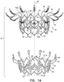
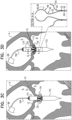
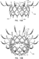
- Implant 20 has an upstream end 24, a downstream end 26, and defines a central longitudinal axis ax1 therebetween.
- Frame assembly 22 comprises a valve frame 30 that comprises a valve body (which is a generally tubular portion) 32 that has an upstream end 34 and a downstream end 36, and is shaped to define a lumen 38 through the valve body from its upstream end to its downstream end.
- Valve body 32 circumscribes axis ax1, and thereby defines lumen 38 along the axis.
- arm 46 extends primarily upstream away from the valve body (e.g., extending radially outward only a little, extending not at all radially outward, or even extending radially inward a little), and the arm then curves to extend radially outward.
- the curvature of arms 46 is described in more detail hereinbelow.
- connecting arm 46 to valve body 32 at site 35 maintains the length of the lumen of the tubular portion, but also advantageously reduces the distance that the tubular portion extends into the ventricle of the subject, and thereby reduces a likelihood of inhibiting blood flow out of the ventricle through the left ventricular outflow tract. It is further hypothesized by the inventors that because each site 35 is a node 100 that connects four joists (whereas each node 100 that is at upstream end 34 connects only two joists), sites 35 are more rigid, and therefore connecting arms 46 to valve body 32 at sites 35 provides greater rigidity to each arm.
- each arm 46 may be individually covered in a sleeve of sheeting 23, thereby facilitating independent movement of the arms.
- Frame assembly 22 further comprises a plurality of legs 50, each of which, in the expanded state, extends radially outward and in an upstream direction from a respective leg-base 66 to a respective leg-tip 68.
- Each leg 50 defines a tissue-engaging flange 54, which is typically the most radially outward part of the leg, and includes leg-tip 68.
- legs 50 are defined by an outer frame (or “leg frame") 60 that circumscribes and is coupled to valve frame 30.
- Frames 30 and 60 define respective coupling elements 31 and 61, which are fixed with respect to each other at coupling points 52.
- frames 30 and 60 are attached to each other only at coupling points 52.
- radial forces may provide further coupling between the frames, e.g., frame 30 pressing radially outward against frame 60.
- coupling points 52 are circumferentially aligned with legs 50 (and flanges 54 thereof), but circumferentially offset with respect to arms 46. That is, the coupling points are typically at the same rotational position around axis ax1 as the legs, but are rotationally staggered with respect to the rotational position of the arms.
- coupling points 52 may be 0.5-3 mm downstream of the widest part of tubular portion 32.
- the longitudinal distance between the widest part of tubular portion 32 and coupling points 52 may be 20-50 percent (e.g., 20-40 percent) of the longitudinal distance between the widest part of the tubular portion and downstream end 36.
- Coupling elements 31 are typically defined by (or at least directly attached to) legs 50. Therefore legs 50 are fixedly attached to frame 30 at coupling points 52. Despite the fixed attachment of legs 50 to frame 30, frame 60 comprises a plurality of struts 70 that extend between, and connect, adjacent legs. Struts 70 are typically arranged in one or more rings 72, e.g., a first (e.g., upstream) ring 74 and a second (e.g., downstream) ring 76. For some applications, and as shown, frame 60 comprises exactly two rings 72. Each ring is defined by a pattern of alternating peaks 64 and troughs 62, the peaks being further upstream than the troughs.
- Each ring is typically coupled to legs 50 at troughs 62 - i.e., such that peaks 64 are disposed circumferentially between the legs. Peaks 64 are therefore typically circumferentially aligned with arms 46. That is, peaks 64 are typically at the same rotational position around axis ax1 as arms 46.
- leg 50 The elongate element of frame 60 that defines leg 50 continues in a downstream direction past ring 74 and coupling element 61, and couples ring 74 to ring 76.
- leg 50 itself is defined as the free portion of this elongate element that extends from ring 74.
- Leg-base 66 may be defined as the region of leg 50 that is coupled to the remainder of frame 60 (e.g., to ring 74). Because each leg 50 extends in a generally upstream direction, leg-base 66 may also be defined as the most downstream region of leg 50.
- valve body 32 extends in a first longitudinal direction (i.e., in a generally downstream direction) away from gap 57, and arms 46 extend in a second longitudinal direction (i.e., in a generally upstream direction) away from the gap.
- first longitudinal direction i.e., in a generally downstream direction
- arms 46 extend in a second longitudinal direction (i.e., in a generally upstream direction) away from the gap.
- valve body 32 is closer to the open end of capsule 90 than is gap 57, and arms 46 (e.g., ball 48) are further from the open end of capsule 90 than is gap 57.
- a downstream limit of gap 57 is defined by the tips of flanges 54.
- an upstream limit of gap 57 is defined by the downstream side of arms 46.
- frame 60 is disposed only downstream of toroidal gap 57, but the frame 30 is disposed both upstream and downstream of the toroidal gap.
- implant 20 comprises a polytetrafluoroethylene (e.g., Teflon) ring 78 attached to downstream end 26.
- Ring 78 circumscribes lumen 38 at downstream end 36 of valve body 32, and typically at downstream end 26 of implant 20. Therefore ring 78 serves as a downstream lip of lumen 38.
- ring 78 is attached (e.g., stitched) to both frame 30 and frame 60.
- ring 78 may be attached to frame 60 at troughs 62.
- ring 78 is stitched to downstream end 36 of valve body 32 by stiches 99 that wrap around the ring (i.e., through the opening of the ring and around the outside of the ring) but do not pierce the ring (i.e., the material of the ring).
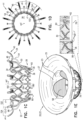
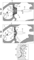
- Implant 20 is delivered, in its compressed state, to native valve 10 using a delivery tool 160 that is operable from outside the subject ( Fig. 3A ).
- Tool 160 typically comprises an extracorporeal controller 162 (e.g., comprising a handle) at a proximal end of the tool, and a shaft 164 extending from the controller to a distal portion of the tool.
- the tool typically comprises a capsule 170 comprising one or more capsule portions 172, 174 (described below), and a mount 166.
- Mount 166 is coupled (typically fixed) to shaft 164.
- Controller 162 is operable to control deployment of implant 20 by transitioning the tool between a delivery state ( Fig. 3A ), an intermediate state ( Fig.
- Implant 20 is delivered within capsule 170 of tool 160 in its delivery state, the capsule retaining the implant in the compressed state.
- Implant 20 typically comprises one or more appendages 80 at downstream end 26, each appendage typically shaped to define a catch or other bulbous element at the end of the appendage, and to engage mount 166, e.g., by becoming disposed within notches in the mount.
- Appendages 80 are typically defined by valve frame 30, but may alternatively be defined by outer frame 60.
- Capsule 170 retains appendages 80 engaged with mount 166 by retaining implant 20 (especially downstream end 26 thereof) in its compressed state.
- a transseptal approach such as a transfemoral approach, is shown.
- frame assembly 22 of implant 20 is as shown in Fig. 2 .
- tool 160 is positioned such that when flanges 54 are deployed, they are deployed within atrium 6 and/or between leaflets 12 of the subject. Subsequently, the tool is moved downstream (distally, for a transseptal approach) until the leaflets are observed to coapt upstream of flanges 54 ( Fig. 3C ).
- flanges 54 may be initially deployed within ventricle 8.
- implant 20 is moved upstream, such that flanges 54 engage leaflets 12 of valve 10 ( Fig. 3D ).
- leaflets 12 of native valve 10 are sandwiched between upstream support portion 40 (e.g., annular sheet 25 thereof) and legs 50 (e.g., flanges 54 thereof). It is to be noted that appendages 80 remain engaged with mount 166.
- delivery tool 160 is transitioned into its open state, thereby allowing implant 20 to expand toward its expanded state (i.e., such that tubular portion 32 widens to its fully-expanded state) ( Fig. 3F ).
- capsule-portion 172 may be moved distally with respect to mount 166 and/or implant 20.
- the resulting expansion of downstream end 26 of implant 20 disengages appendages 80, and thereby implant 20 as a whole, from mount 166.
- Appendages 80 are not visible in Fig. 3F (or Fig. 3C ) because they are obscured by ring 78.
- Tool 160 (e.g., capsule-portion 172 thereof) may then be withdrawn via lumen 38 of implant 20, and removed from the body of the subject.
- FIGs. 4 , and 5A-C are schematic illustrations of implants, in accordance with some applications of the invention.
- Fig. 4 shows an implant 120.
- Fig. 5A shows an implant 220
- Fig. 5B shows a frame assembly 222 of implant 220 after shape-setting
- Fig. 5C shows a valve frame 230 of frame assembly 222 prior to shape-setting (i.e., the shape-set valve-frame structure).
- Implants 120 and 220 are typically the same as implant 20, described hereinabove, except where noted.
- Sheeting 23 forms annular sheet 25 that is disposed over and typically stitched to arms 46.
- Implant 120 thereby comprises valve body 32 (e.g., as described hereinabove), and an upstream support portion 140 that itself comprises arms 46 and annular sheet 25.
- implant 220 comprises valve body 32 and an upstream support portion 240 that itself comprises arms 46 and annular sheet 25.
- projection 146 and 246 are distinct from appendages 80, which are disposed at the other end of the valve body.
- projections 146 extend from sites 35 in a similar way to arms 46.
- Projections 146 may be structurally similar to arms 46, and may even be identically cut when frame 30 is initially cut from the original metal tube (i.e., in the raw valve-frame structure).
- projections 146 have a different curvature to arms 46 (e.g., they may be bent differently post-cutting), and are curved such that they extend through annular sheet 25.
- arms 46 typically reach and press against the atrial wall
- projections 146 are typically shaped such that nubs 148 are not in contact with the atrial wall.
- each projection 146 replaces an arm 46, such that the cumulative sum of arms and projections is twelve.
- Fig. 4 shows an embodiment comprising six arms 46 and six projections 146, but the scope of the invention includes other ratios, such as nine arms 46 and three projections 146.
- projections 246a of variant 230a are longer than projections 246 of frame 230, and nubs 248a are therefore disposed between wide portions 46c of arms 46.
- at least the arms 46 that are adjacent to nubs 248a are deflected circumferentially (which is represented two-dimensionally as being laterally deflected) compared to their positions in frame 230, and are typically unevenly spaced.
- arms 46 are typically circumferentially displaced, e.g., such that they are evenly spaced.
- Variant 230a may be used in place of any other valve frame described herein, mutatis mutandis.
- variant 230a may be used in combination with other technologies described herein, mutatis mutandis.
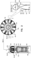
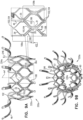
- FIG. 7 is a schematic illustration of an outer frame 60a, in accordance with some applications of the invention.
- Outer frame 60a is typically identical to outer frame 60 except that peaks 64a of frame 60a have a larger radius of curvature than do peaks 64 of frame 60.
- Outer frame 60a may be used in place of any other outer frame described herein, mutatis mutandis.
- frame 60a may be used in combination with other technologies described herein, mutatis mutandis.
- FIG. 8 is a schematic illustration of a frame assembly 22b, in accordance with some applications of the invention.
- Frame assembly 22b comprises a valve frame 30b and an outer frame 60b. Except where noted, frame assembly 22b, valve frame 30b, and outer frame 60b are as described for frame assembly 22, valve frame 30, and outer frame 60, respectively.
- Outer frame 60b comprises (or defines) (1) a first (e.g., upstream) ring 74b defined by a pattern of alternating first-ring peaks and first-ring troughs, (2) a second (e.g., downstream) ring 76b defined by a pattern of alternating second-ring peaks and second-ring troughs, and a plurality of legs 50, each of the legs coupled to the first ring and the second ring, and extending radially outward.
- a first (e.g., upstream) ring 74b defined by a pattern of alternating first-ring peaks and first-ring troughs
- a second (e.g., downstream) ring 76b defined by a pattern of alternating second-ring peaks and second-ring troughs
- the cellular structure of the valve frames described herein may also be viewed as defining rings of alternating peaks and troughs, the rings circumscribing the longitudinal axis of the implant.
- the waveform (i.e., the peak-trough waveform) of the rings of the outer frame are in phase with each other
- the phase of the waveform of the rings of the valve frame typically alternate with respect to each other. That is, for the valve frame, the waveform of one ring is out of phase (e.g., is in antiphase) with that of its axially-adjacent rings.
- valve frame 30 defines a first (e.g., upstream) ring 182, a second (e.g., middle) ring 184, and a third (e.g., downstream) ring 186, and ring 184 is in antiphase with rings 182 and 184.
- Valve frame 30b similarly defines a first (e.g., upstream) ring 182b, a second (e.g., middle) ring 184b, and a third (e.g., downstream) ring 186b, and ring 184b is in antiphase with rings 182b and 184b.
- the waveform of one of outer frame rings is in-phase with the waveform of the inner frame ring with which it is axially aligned
- the waveform of one of outer frame rings is out of phase (e.g., is in antiphase) with the waveform of the inner frame ring with which it is axially aligned.
- ring 74 is in-phase with the ring of the inner frame with which it is axially aligned (ring 184)
- ring 76 is in antiphase with the ring of the inner frame with which it is axially aligned (ring 186).
- ring 74b is in-phase with the ring of the inner frame with which it is axially aligned (ring 184b), whereas ring 76b is in antiphase with the ring of the inner frame with which it is axially aligned (ring 186b).
- ring 76b is in antiphase with ring 186b, the peaks of ring 76b are not disposed directly radially outward from respective parts of frame 30b, and therefore are not in contact with frame 30b. However, despite ring 74b being in phase with ring 184b, and the peaks of ring 74b being disposed directly radially outward from respective parts of frame 30b, the peaks of ring 74b are also not in contact with frame 30b. That is, frame assembly 22 defines a radial gap 188 between frames 30 and 60 at the peaks of ring 74b. Typically, therefore, none of the peaks of the rings of frame 60b is in contact with inner frame 30b. In contrast, for frame assembly 22, although the peaks of ring 76 are not in contact with frame 30, the peaks of ring 74 typically are in contact with frame 30.
- frame assembly 22b may be used in combination with other implants described herein.
- other frame assemblies described herein may be shaped to define gap 188, mutatis mutandis.
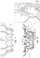
- FIGs. 9A-B are schematic illustrations of an inner frame 330a, and an implant 320a comprising inner frame 330a, in accordance with some applications of the invention.
- Inner frame 330a may be used in place of other inner frames of implants described herein, mutatis mutandis.
- frame 330a may be used in combination with other technologies described herein, mutatis mutandis.
- Inner frame 330a comprises a valve body (which is a generally tubular portion) 332a that has an upstream end 334a and a downstream end 336a, and is shaped to define a lumen through the valve body from its upstream end to its downstream end.
- Valve frame 330a further comprises a plurality of arms 46, each of which, in the expanded state, extends radially outward from valve body 332a.
- the additional joists are hypothesized by the inventors to increase the resistance of the valve body to compression toward axis ax1, including resistance to circumferential compression (e.g., compression that would otherwise reduce the diameter of the valve body, but that would retain the valve body in a generally cylindrical shape) and localized compression (e.g., compression that would otherwise reduce the diameter of the valve body at only certain locations, causing the valve body to become more oval in transverse cross-section).
- circumferential compression e.g., compression that would otherwise reduce the diameter of the valve body, but that would retain the valve body in a generally cylindrical shape
- localized compression e.g., compression that would otherwise reduce the diameter of the valve body at only certain locations, causing the valve body to become more oval in transverse cross-section.
- major nodes 106 connect 6 joists (again, excluding arms 46, which are not joists of the valve body's cellular structure).
- minor nodes 104 connect 2 joists. Therefore, for some applications, none of the nodes 102 of the cellular structure of valve body 332a connects 4 joists.
- the cells of the cellular structure of valve body 332a comprise a first circumferential row 109a of cells, and a second circumferential row 109b of cells. That is, row 109a is a row of first-row cells, and row 109b is a row of second-row cells.
- Each of the cells of row 109a is connected to each of its circumferentially-adjacent first-row cells at a respective major node 106.
- each of the cells of row 109a is longitudinally delimited by two minor nodes 104 (i.e., the upstream end and the downstream end of each cell is at a respective minor node). It is to be noted that, typically, each of the cells of row 109a is not connected to another cell at these minor nodes 104 (i.e., the minor nodes that longitudinally delimit the first-row cell).
- each of the major nodes 106 at which circumferentially-adjacent first-row cells are connected is also the major node that longitudinally-delimits a respective second-row cell (e.g., at the upstream end of the second-row cell).
- that common major node 106 is also site 35, at which arms 46 are attached to the valve body.
- valve body 332a The cells of the cellular structure of valve body 332a are typically delimited by exactly four nodes 102.
- Frame 330a defines coupling elements 31, which are fixed to coupling elements 61 of frame 60 at coupling points, as described hereinabove for frame assembly 22, mutatis mutandis.
- coupling elements 31 are defined by respective major nodes 106. Therefore, for some applications, a frame assembly comprises (i) inner frame 330a that defines valve body 332a, and (ii) an outer frame (e.g., frame 60) that circumscribes the valve body, and is coupled to the inner frame by being fixed to major nodes of the valve body.
- coupling elements 31 are typically defined by the major nodes at which circumferentially-adjacent second-row cells are connected.
- valve body 332a is defined by exactly two stacked, tessellated rows 109 of cells. That is, typically, first row 109a is the most upstream row, second row 108b is the most downstream row, and these two rows are tessellated with each other. Therefore, for some applications, all the cells of the cellular structure of valve body 332a are either first-row cells or second-row cells.
- one of the joists connects to another major node 106, but the other joist connects to a minor node 104 that is disposed a distance d12 away from the major node at the second end of the pair.
- one of the joists connects to a first minor node, and the other joist connects to another minor node that is disposed a distance d12 away from the first minor node.
- Distance d12 is typically 0.1-1 mm (e.g., 0.25-0.9 mm, such as 0.25-0.65 mm).
- the arrangement of joists 28 in pairs 108 results in the joists that delimit the cells of first row 109a not delimiting the cells of second row 109b. That is, for some applications, no individual joist 28 delimits both a first-row cell and a second-row cell.
- valve body 332a Another aspect of valve body 332a is as follows: Major nodes 106 are typically arranged in major-node rows, each major-node row circumscribing longitudinal axis ax1 at a respective major-node-row longitudinal site, and minor nodes 104 are typically arranged in minor-node rows, each minor-node row circumscribing the longitudinal axis at a respective minor-node-row longitudinal site.
- the minor-node-row longitudinal sites alternate with the major-node-row longitudinal sites.
- At least 3 minor-node-row longitudinal sites alternate with at least 2 major-node-row longitudinal sites, e.g., in the order minor-major-minor-major-minor, as shown.
- Inner frame 330b comprises a valve body (which is a generally tubular portion) 332b that has an upstream end 334b and a downstream end 336b, and is shaped to define a lumen through the valve body from its upstream end to its downstream end.
- Valve frame 330b further comprises a plurality of arms 46, each of which, in the expanded state, extends radially outward from valve body 332b.
- Inner frame 330b is typically the same as inner frame 330a, except where noted.
- inner frame 330b comprises additional joists 28 at upstream end 334b. That is, in contrast to inner frame 330a, for inner frame 330b pairs 108 of joists are also disposed at the upstream side of the upstream row of cells.
- sites 37 are coincident with the upstream extremity of a respective upstream-row cell.
- sites 37 are not coincident with the upstream extremity of a respective upstream-row cell. Rather, sites 37 are coincident with a minor node that joins the joists that are paired with (e.g., that are parallel with) the joists of the respective upstream-row cell.
- Implant 320b is typically the same as implant 320a, except that it comprises inner frame 330b instead of inner frame 330a.
- FIGs. 11A-B are schematic illustrations of an inner frame 330c, and an implant 320c comprising inner frame 330c, in accordance with some applications of the invention.
- Inner frame 330c may be used in place of other inner frames of implants described herein, mutatis mutandis.
- Inner frame 330c comprises a valve body (which is a generally tubular portion) 332c that has an upstream end 334c and a downstream end 336c, and is shaped to define a lumen through the valve body from its upstream end to its downstream end.
- Valve frame 330c further comprises a plurality of arms 46, each of which, in the expanded state, extends radially outward from valve body 332c.
- Inner frame 330c is typically the same as inner frame 330b, except where noted.
- a cellular structure that defines fewer, larger cells advantageously facilitates radial compression (i.e., "crimping") to a smaller diameter than does a comparable cellular structure that defines more, smaller cells.
- crimping radial compression
- this is typically at the expense of strength and rigidity of the expanded valve.
- additional joists 28 e.g., in inner frames 330a, 330b, and 330c
- pairs 108 is hypothesized to increase strength and rigidity, in particular with respect to compression toward the central longitudinal axis.
- valve body 332c of inner frame 330c has fewer, larger cells compared to valve body 32 of inner frame 30, and is therefore radially compressible to a smaller diameter.
- each row of cells of valve body 32 includes 12 cells
- each row of cells of valve body 332c includes 9 cells.
- the rotationally-symmetrical pattern of valve body 32 has 12 repeats (e.g., 12 cells per cell row, 12 minor nodes per minor-node row, 12 major nodes per major-node row, 12 coupling elements, 12 arms 46)
- the rotationally-symmetrical pattern of valve body 332c has only 9 repeats.
- valve body 32 and valve body 332c typically have 3 appendages 80 and 3 projections 246.
- Both valve body 32 and valve body 332c define two rows of cells. Therefore, whereas valve body 32 defines 24 cells in total, valve body 332c defines 18 cells in total. Whereas valve body 32 defines exactly 24 major nodes, valve body 332c defines exactly 18 major nodes.
- inner frame 330c comprises additional joists 28 at upstream end 334c (e.g., similarly to inner frame 330b). That is, for such applications, pairs 108 of joists are typically also disposed at the upstream side of the upstream row of cells of inner frame 330c.
- implant 320c is typically the same as implant 320b, except that implant 320c comprises 9 rotationally-symmetrical repeats, rather than 12.
- inner frame 330c does not comprise additional joists 28 at upstream end 334c, and is instead more like inner frame 330a in this regard.
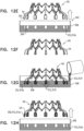
- Figs. 12A-H are schematic illustrations of a technique for use with a frame of a prosthetic valve, in accordance with some applications of the invention.
- the technique is for augmenting a tissue-engaging flange of the frame with a soft pad 300.
- Figs. 12A-H show the technique being used to augment flanges 54 of outer frame 60 with soft pads 300, but it is to be noted that the technique may be used with any suitable frame, mutatis mutandis.
- Fig. 12A shows frame 60, which has tissue-engaging flanges 54.
- a model 302 of a soft pad 300 with which each flange 54 is to be augmented is affixed to the respective flange ( Fig. 12B ).
- a mold 304 is formed by (i) positioning frame 60 such that models 302 are supported within a fluid 310f of a first substance 310 while the first substance solidifies, and (ii) subsequently, removing the models from the first substance, leaving a cavity in the solidified first substance.
- Figs. 12A shows frame 60, which has tissue-engaging flanges 54.
- a model 302 of a soft pad 300 with which each flange 54 is to be augmented is affixed to the respective flange ( Fig. 12B ).
- a mold 304 is formed by (i) positioning frame 60 such that models 302 are supported within a fluid 310f of a first substance 310 while the first substance solidifies, and (ii) subsequently
- a bath 306 of fluid 310f may be prepared, and frame 60 may be inverted and lowered into the bath such that models 302 are supported within the fluid ( Fig. 12C ).
- First substance 310 is allowed to solidify into solidified first substance 310s ( Fig. 12D ).
- frame 60 is withdrawn from the bath, thereby removing models 302 from solidified first substance 310s, such that each model leaves a respective cavity 308 in solidified first substance 310s ( Fig. 12E ).
- Models 302 are then removed from flanges 54 ( Fig. 12F ).
- Pads 300 are then formed by: (i) placing flanges 54 in contact with a second substance 312 by repositioning the frame such that each flange is supported within a respective cavity 308, and introducing a fluid 312f of the second substance to the cavity ( Fig. 12G ), and (ii) while the flange remains in contact with the second substance, allowing the second substance to solidify into solidified second substance 312s and to become affixed to the flange.
- flanges 54 are removed from cavities 308 with formed pads 300 (comprising solidified second substance 312s) affixed to the flanges ( Fig. 12H ).
- flanges 54 are not all disposed on the same side of frame assembly 22 (i.e., after frames 30 and 60 have been attached to each other). For example, flanges 54 are not all at the upstream end of the prosthetic valve or at the downstream end of the prosthetic valve. Rather, they are disposed downstream of the tips of arms 46 and upstream of downstream end 26.
- flanges 54 are arranged circumferentially around the longitudinal axis of the prosthetic valve.
- Flanges 54 (and eventually pads 300) are arranged circumferentially around frame 30 longitudinally between the upstream end and the downstream end of frame 30, exclusive.
- the flanges being not all disposed on the same side might inhibit the use of the technique of Figs. 12A-H to simultaneously augment all of the flanges.
- the two-frame nature of frame assembly 22 advantageously allows flanges 54 to be augmented with pads before frame 60 is attached to frame 30. Because all of flanges 54 are disposed at the same side (e.g., the upstream side) of frame 60, they can all be placed into the fluid substances simultaneously.
- annular bath is positioned circumscribing the central portion of the prosthetic valve or frame assembly, such that all flanges can be placed into the fluid substances even when the flanges are not all disposed on the same side of a prosthetic valve or frame assembly.
- substance 310 and/or substance 312 may be a mixture of constituents that is initially fluid upon mixing, and that solidifies as the constituents react with each other.
- fluid substance 310f and/or fluid substance 312f is fluid because it is in a molten state, and solidifies as it cools.
- second substance 312 is typically soft, flexible, and/or resilient.
- second substance 312 (or at least solidified second substance 312s) is a foam.
- second substance 312 comprises silicone, polyurethane, a thermoplastic elastomer such as Santoprene (TM), and/or polyether block amide.
- Figs. 12A-H are alternatively or additionally used, mutatis mutandis , to augment the downstream end of the implant with one or more pads, e.g., to serve a similar function to ring 78 described hereinabove.
- FIGS. 13A-E , 14A-D , 15A-C , 16A-C , 17 , 18A-C , and 19 are schematic illustrations of an implant 420, and steps in the assembly of the implant, in accordance with some applications of the invention.
- these figures illustrate steps in the attachment of various flexible components to the frame assembly of the implant, such as steps in the dressing of the frame assembly with various sheets of flexible material.
- Implant 420 is shown as comprising frame assembly 222, and is typically identical to implant 220 except for where described otherwise.
- the steps described with reference to Figs. 13A-18C may be used, mutatis mutandis , to assemble other implants, including the other implants described herein.
- Figs. 13A-E show flexible components of implant 420.
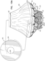
- Figs. 13A-B are perspective and side views, respectively, of a valvular assembly 430, comprising leaflets 58 arranged to serve as a check valve.
- each leaflet 58 defines (i) an upstream surface 457, past which blood will flow through implant 420 in an upstream-to-downstream direction, and (ii) a downstream surface 459, against which blood will press when the valvular assembly closes and inhibits blood flow in a downstream-to-upstream direction.
- Valvular assembly 430 typically further comprises a liner 427 and/or a plurality of connectors 432.
- Liner 427 of implant 420 generally corresponds to liner 27 of implant 20, mutatis mutandis.
- valvular assembly 430 comprises three leaflets 58 and three connectors 432.
- Connectors 432 couple the leaflets to each other to form commissures, and are used to secure the leaflets, at the commissures, to frame assembly 222.
- Connectors 432 are arranged circumferentially, and leaflets 58 extend radially inward from the connectors.
- valvular assembly 430, and connectors 432 in particular are as described in PCT patent application publication WO 2018/029680 to Hariton et al. , and/or US patent application 15/878,206 to Hariton et al. , both of which are incorporated herein by reference.
- Each leaflet 58 is attached (e.g., stitched) to liner 427 along a line (e.g., a stitch line) 437.
- Each leaflet 58 defines a free edge 458, which is typically straight, and at which the leaflet coapts with the other leaflets 58.
- Stitch line 437 is typically curved.
- Each leaflet typically defines a curved edge (e.g., an upstream edge) 456 at which the leaflet is attached to liner 427.
- edge 456 and/or stitch line 437 is concave toward the downstream end of valvular assembly 430, such that edge 456 and/or stitch line 437 (i) become closer to the downstream end of the valvular assembly at connectors 432, and (ii) are closest to the upstream end of the valvular assembly about midway circumferentially between the connectors. That is, edge 456 has an apex about midway circumferentially between connectors 432.
- leaflets 58 extend further axially downstream (i.e., downstream with respect to axis ax1) than does liner 427. Therefore, a downstream portion of each leaflet 58 is typically circumferentially exposed from liner 427.
- liner 427 is shaped to define regions 428 at which a downstream edge 436 of the liner recedes from the downstream end of valvular assembly 430. At each region 428, more of the respective leaflet 58 is circumferentially exposed.
- Each region 428 is typically circumferentially aligned with the concavity defined by edge 456 and/or stitch line 437.
- downstream edge 436 of liner 427 is typically stitched to ring 182 of frame 230. Therefore, for some applications, the most upstream parts of downstream edge 436 of liner 427 are closer to the upstream end of the implant than is the most downstream parts of arms 46. As described in more detail hereinbelow, in implant 420, regions 428 of liner 427 facilitate the provision of windows 482 into a pouch 490.
- Fig. 13C shows a sheet 440 of flexible material.
- sheet 440 is provided flat, and in the shape of a major arc of an annulus, having a first arc-end 442a and a second arc-end 442b.
- Sheet 440 of implant 420 generally corresponds to annular sheet 25 of implant 20, mutatis mutandis.
- Fig. 13D shows a sheet 450 of flexible material.
- Sheet 450 is annular, and defines an inner perimeter 452, an outer perimeter 454, and a radial dimension d21 therebetween.
- Fig. 13E shows a sheet 460 of flexible material.
- Sheet 460 is shaped to define a belt 462 and a plurality of elongate strips 464.
- Each strip 464 defines a respective central strip-axis ax2, and extends along its strip-axis from belt 462 to the end 466 of the strip.
- belt 462 is linear and defines a belt-axis ax3, and strip-axis ax2 is orthogonal to the belt-axis.
- strips 464 are parallel to each other.
- Each strip 464 has first and second edges 468 (e.g., a first edge 468a and a second edge 468b), which extend on either side of axis ax2, between belt 462 and end 466.
- sheets 440, 450, and 460 may all be considered components of sheeting 23.
- liner 427, sheet 440, sheet 450, and/or 460 comprise (e.g., consist of) the same material as each other.
- sheets 440, 450, and 460 are provided as flat, and are subsequently shaped during assembly of implant 420, e.g., as described hereinbelow.
- sheet 440 is shaped into an open frustum by attaching (e.g., stitching) ends 442a and 442b together ( Figs. 14A-B ). This is represented by a stitch line 444 in Fig. 14B .
- sheet 440 may be provided in the open frustum shape.
- the open frustum shape has a greater perimeter 446 at a first base of the frustum, and a smaller perimeter 448 at a second base of the frustum.
- Perimeter 448 defines an opening, and sheet 440 is stitched to arms 46 such that the opening is aligned with the lumen defined by valve body 32 of frame 30 ( Fig. 14C ), and typically such that the sheet covers an upstream side of the arms.
- Fig. 14D shows valvular assembly 430 having been coupled to frame assembly 222. This step may be performed after sheet 440 is stitched to arms 46 (as shown) or beforehand.
- Valvular assembly 430 is placed inside valve body 32 of frame 30, and is attached by stitching connectors 432 and liner 427 to frame assembly 222. Connectors 432 are typically stitched to ring 184 and/or ring 186.
- connectors 432 to frame assembly 222 is as described in PCT patent application publication WO 2018/029680 to Hariton et al., and/or US patent application 15/878,206 to Hariton et al., both of which are incorporated herein by reference.
- Smaller perimeter 448 of sheet 440 is stitched to an upstream edge 434 of liner 427, to form a substantially sealed channel through implant 420.
- This stitching is represented by a stitch line 435.
- projections 246 extend between, and are sandwiched between, perimeter 448 of sheet 440 and upstream edge 434 of liner 427.
- Upstream edge 434 is typically circular.
- Downstream edge 436 of liner 427 is stitched to valve body 32 of frame 30.
- downstream edge 436 is shaped and positioned to approximately conform to rings 182 and 184, and is stitched to these rings.
- stitching of a perimeter or edge of a sheet to a perimeter or edge of another sheet does not necessarily mean that the sheets are stitched at their absolute edges (i.e., their free edges). Rather, in this context, the "perimeter” or “edge” also includes the adjacent area of the sheet, as is understood by one of ordinary skill in the stitching art, and as is typically required for effective stitching.
- Valvular assembly 430 is typically positioned within frame assembly such that the apex of curved edge 456 of each leaflet 58 is disposed axially close to (e.g., axially within 2 mm of, e.g., within 1 mm of) an upstream end 34 of valve body 32. Valvular assembly 430 is also typically positioned within frame assembly such that free edge 458 of each leaflet 58 is disposed downstream of leg 50.
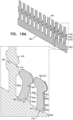
- sheet 450 is attached to frame assembly 222 ( Figs. 15A-C ).
- Outer perimeter 454 of sheet 450 is stitched to greater perimeter 446 of the sheet 440 ( Fig. 15A ). This is represented by stitch line 455.
- perimeter 454 is larger than perimeter 446, and is brought inwards to be stitched to perimeter 446 (e.g., making sheet 450 frustoconical), with inner perimeter 452 disposed axially away from frame assembly 222 (e.g., further axially away than outer perimeter 454 from the frame assembly).
- sheet 450 is everted by bringing inner perimeter 452 toward frame assembly 222, and passing the inner perimeter around the tips of arms 46 - i.e., axially past the tips of all of the arms ( Fig. 15B ).
- arms 46 collectively define an arm-span d23 that is wider than perimeter 452. That is, the tips of arms 46 typically define a perimeter that is greater than perimeter 452.
- the passage of inner perimeter 452 around the tips of arms 46 is facilitated by bending (e.g., temporarily) one or more of arms 46.
- Inner perimeter 452 is advanced over at least part of valve body 32 toward a downstream end of frame assembly 222, and is stitched in place.
- perimeter 452 is advanced between the valve body and legs 50, such that perimeter 452 circumscribes valve body 32, and legs 50 are disposed radially outside of sheet 450.
- each leg 50 extends radially outward and in an upstream direction from a respective leg-base 66 to a respective leg-tip 68.
- Each leg therefore extends at an acute angle to define a respective cleft 250 between the leg and valve body 32 (e.g., the tubular portion), the cleft open to the upstream direction.
- perimeter 452 is tucked into clefts 250, and is stitched into place.
- Frame assembly 222 defines a distance d22, measured along a straight line, between the ends of arms 46 and clefts 250.
- distance d22 may be defined as a distance between (i) an imaginary ring described by the ends of arms 46, and (ii) an imaginary ring described by clefts 250.
- sheet 450 defines an inflatable pouch 490 that is bounded by sheet 450 (e.g., defining an outer and/or downstream wall of the pouch), sheet 440 (e.g., defining an upstream wall of the pouch), and liner 427 (e.g., defining an inner wall of the pouch).
- Pouch 490 typically circumscribes the longitudinal axis of the implant and/or the valve body of frame assembly 222 (e.g., the pouch is a cuff), and further typically extends radially outward from the valve body.
- an upstream portion of pouch 490 is attached to valve frame 30 (e.g., and is not attached to outer frame 60), and a downstream portion of the pouch is attached to the outer frame.
- at least one respective window 482 into pouch 490 is defined between each leaflet 58 and perimeter 452.
- Fig. 16A-C show steps in dressing frame assembly 222 with sheet 460, in accordance with some applications of the invention.
- Each strip 464 is formed into a respective pocket 478 ( Figs. 16A-B ).
- Each strip is folded over itself, about a fold-line 463 that is orthogonal to strip-axis ax2, thereby forming (i) a first strip-portion 464a that extends from belt 462 to the fold-line, and (ii) a second strip-portion 464b that extends from fold-line back toward the belt.
- First strip-portion 464a and second strip-portion 464b are stitched together at first edge 468a and second edge 468b.
- the resulting pocket 478 is typically elongate, and has (i) an opening 470 defined at least in part by end 466 of the strip, and (ii) a tip 472 at the fold-line.
- a soft pad 476 is provided in each pocket 478, typically at tip 472.
- pad 476 is formed from a piece of foam 474 (e.g., comprising polyurethane).
- Piece of foam 474 may initially be generally cubic.
- piece of foam 474 is folded to form a niche 477 in pad 476, typically after having been at least partly flattened by compression.
- Pad 476 may be introduced into pocket 478 before the pocket is fully formed (e.g., as shown), or may be subsequently introduced into the pocket via opening 470.
- pads 300 may be used in place of pads 476, and may be added to flanges 54 as described with reference to Figs. 12A-H , mutatis mutandis.
- each strip-portion 464a and 464b typically defines a widened region 479 adjacent to fold-line 463, such that when pockets 478 are formed, a receptacle for pad 476 is formed.
- Pockets 478 are subsequently slid onto legs 50, and belt 462 is wrapped around frame assembly 222 downstream of legs 50 (e.g., downstream of the axial level at which the legs are coupled to the valve body).
- Belt 462 is typically positioned such that it is disposed over the commissures of leaflets 58 and/or over connectors 432. That is, the belt is typically wrapped around the frame assembly at an axial level such t
- flanges 54 of legs 50 are typically advanced into niches 477 of the pads.
- Belt 462 (e.g., the edge of the belt from which pockets 478 extend) is stitched to sheet 450. More specifically, the upstream edge of belt 462 is stitched circumferentially to perimeter 452 of sheet 450.
- tips 472 and/or pads 476 are further secured to flanges 54 by stitching 475, which may pass through a hole 55 (labeled in Fig. 1A ) defined in each flange 54. Stitching 475 is visible in Figs. 18A-C .
- polytetrafluoroethylene ring 78 is typically also attached to frame assembly 222.
- ring 78 is also stitched to belt 462 (e.g., to the edge of the belt opposite pockets 478 - i.e., the downstream edge of the belt).
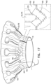
- Fig. 17 shows a ribbon 480 being wrapped around the leg-base 66 of each leg 50, in accordance with some applications of the invention.
- the ends of ribbon 480 overlap. Ribbons 480 are stitched in place, but the stitches are typically not disposed in cleft 250.
- ribbons 480 may be stitched to belt 462.
- ribbons 480 are shown being used in combination with pockets 478 (and are therefore wrapped around the pockets at leg-base 66), it is to be noted that ribbons 480 may alternatively be used for applications in which legs 50 are generally uncovered.
- Ribbon 480 covers cleft 250, and is hypothesized by the inventors to reduce a likelihood of tissue (e.g., leaflet or chordae tissue) from becoming wedged in and/or damaged by the cleft.
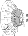
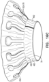
- Figs. 18A-C show implant 420 after its assembly.
- Fig. 18A is an upper perspective view (e.g., showing upstream surfaces of the implant)
- Fig. 18B shows a side view
- Fig. 18C shows a lower perspective view (e.g., showing downstream surfaces of the implant).
- implant 20 (which comprises frame assembly 22) is secured in place at the native valve by sandwiching tissue of the native valve between the implant's upstream support portion 40 and flanges 54.
- Implants that comprise frame assembly 222, such as implant 220 are typically secured in the same way, mutatis mutandis.
- Implants that further comprise pouch 490, such as implant 420 are typically secured similarly, but with pouch 490 disposed between the upstream support portion and the tissue of the native valve. Therefore in at least some regions of implant 420, the tissue of the native valve is sandwiched between flanges 54 and pouch 490, e.g., as shown in Fig. 19 .
- Windows 482 open into pouch 490 from the lumen of the valve body. Once implant 420 has been implanted at the native valve, windows 482 are disposed functionally within ventricle 8, whereas at least portions of pouch 490 are disposed functionally within atrium 6. Therefore, during ventricular systole, ventricular pressure (which is much greater than atrial pressure) forces blood into pouch 490, thereby inflating the pouch. This inflation presses pouch 490 against the tissue of the native valve. It is hypothesized by the inventors that this inhibits paravalvular leakage of blood, especially during ventricular systole. For example, the pouch may seal a paravalvular gap at the commissures of the native valve.
- pouch 490 squeezes tissue of the native valve (e.g., native leaflets) between the pouch and flanges 54.
- Pouch 490 is typically dimensioned such that if, in a particular region, tissue is not disposed between a flange 54 and pouch 490, inflation of the pouch presses the pouch against the flange.
- apparatus comprising:
- the first sheet, the second sheet, and the liner define inflatable pouch 490 therebetween, the first sheet defining an upstream wall of the pouch, the second sheet defining a radially-outer wall of the pouch, and the liner defining a radially-inner wall of the pouch.
- the apparatus defines a plurality of windows (e.g., windows 482) from the lumen into the pouch, each of the windows bounded by the liner at upstream edges of the window, and bounded by the second perimeter and/or belt 462 at a downstream edge of the window.
- Each window 482 is typically discrete - i.e., bounded on all sides, and separate from other windows.
- downstream edge 436 of liner 427 is stitched to ring 182 of frame 230, the most upstream parts of windows 482 are closer to the upstream end of the implant than are the most downstream parts of arms 46
- pouch 490 circumscribes the valve body of implant 420.
- each window 482 spans more than one cell of the valve body. This is represented by the multiple instances of reference numeral 482 in Fig. 18C .
- each window spans at least partly of five cells of the valve body.
- each window spans substantially all of two cells (e.g., two cells of row 29a) and about half (e.g., 40-60 percent) of each of three cells (e.g., three cells of row 29b).
- Each window 482 is bounded by liner 427 at an upstream edge of the window.
- each window 482 is defined at rings 182 and 184 of valve frame 230, at which region 428 of liner 427 is stitched to the valve frame.
- the window is bounded by perimeter 452, and also by belt 462. Therefore, at the downstream edge of each window 482, the window may be considered to be bounded by stitch line 465.
- the upstream edge of each window 482 is the shape of a capital letter M, e.g., with the apices of the letter M at upstream end 34 of the valve body, and with the vertex of the letter M at a site 35. Because region 428 of liner 427 follows, and is stitched to, the joists of valve frame 230 at region 428 of the liner, it is hypothesized by the inventors that this arrangement reinforces the upstream edge of window 482, e.g., increasing durability compared to an arrangement in which the upstream edge of the window crosses between joists of the valve frame.
- sheet 440 typically covers an upstream side of arms 46. Once pouch 490 has been formed, at least most of each arm 46 is therefore disposed inside the pouch. As also described hereinabove, sheet 440 is stitched to arms 46. Once pouch 490 has been formed, the pouch (i.e., the part of the pouch defined by sheet 440) is therefore stitched to arms 46,
- a circumferential stitch line 445 is used to stitch sheet 440 to sheet 450 at a radius smaller than the overall radius of upstream support portion 40 (i.e., radially inward from the tips of arms 46), typically sandwiching arms 46 between these two sheets.
- Stitch line 445 is typically radially aligned with region 154 and/or wide (and flexible) portion 46c of arm 46. This typically creates a region 484 in which the portions of sheets 440 and 450 that are disposed radially outward from stitch line 445 are isolated from pouch 490.
- the ends of arms 46 are therefore typically disposed in region 484, and are isolated from pouch 490.
- sheet 450 is sufficiently baggy that the sheet (e.g., pouch 490) may extend radially outward beyond arms 46, particularly if uninhibited by tissue of the native valve. This may be achieved by radial dimension d21 of sheet 450 being greater than distance d22 between the ends arms 46 and clefts 250.
- dimension d21 is more than 30 percent greater (e.g., more than 50 percent greater) than distance d22.
- dimension d21 may be 30-100 percent greater (e.g., 30-80 percent greater, e.g., 40-80 percent greater, such as 50-70 percent greater) than distance d22.
- pouch 490 may extend radially outward beyond arms 46 irrespective of the presence of stitch line 445, which is disposed radially-inward from the ends of arms 46.
- pouch 490 extends, with respect to the longitudinal axis of implant 420, further upstream than the leaflets. That is, for some applications, upstream regions of pouch 490 (e.g., those closest to prosthetic valve support 40) are situated further upstream than even the apex of curved edge 456 of leaflets 58.
- each of leaflets 58 is attached to liner 427 upstream of windows 482. That is, at least the apex of curved edge 456 of leaflets 58 is disposed upstream of windows 482.
- Free edge 458 of each leaflet 58 is typically disposed downstream of the third axial level - i.e., the axial level at which perimeter 452 of sheet 450 is attached to frame assembly 222. That is, leaflets 58 typically extend further downstream than pouch 490.
- the third axial level i.e., the axial level at which perimeter 452 of sheet 450 is attached to frame assembly 222
- the second axial level i.e., the axial level at which legs 50 are attached to the valve body
- valve body 32 is typically not lined - i.e., no liner is typically disposed between leaflets 58 and frame 30.
- belt 462 circumscribes valve body 32 and serves a similar function to a liner - channeling fluid through the lumen of the valve body.
- projections 246 are not visible in Fig. 18B .
- the projection-length of projections 246 e.g., see projection-length d13 in Fig. 5C ) is such that the projections do not extend further upstream than the tips of arms 46.
- projections 246 extend further upstream than the highest part of arms 46 within concave region 152.
- projections 246 extend to an axial height that is between (a) that of the tips of arms 46, and (b) that of the highest part of arms 46 within concave region 152. This is illustrated perhaps most clearly in Fig. 9A , which shows inner frame 330a, but is applicable to each of the inner frames described herein, mutatis mutandis.
- Figs. 20 , and 21A-C are schematic illustrations of implant 420, in accordance with some applications of the invention.
- Pouch 490 defines an interior space 500.
- arms 46 and legs 50 e.g., flanges 54 thereof
- narrow pouch 490 therebetween to form a narrowed portion 510 of the pouch.
- Narrowed portion 510 typically circumscribes valve body 32 and/or the longitudinal axis of the implant - e.g., the narrowed portion being annular.
- each leg 50 e.g., flange 54 thereof
- sheet 450 which defines a downstream surface of pouch 490
- sheet 440 which defines an upstream surface of the pouch
- arms 46 and legs 50 alternate circumferentially. That is, when viewed from above, an arm 46 is disposed circumferentially on either side of each leg 50, and a leg is disposed circumferentially on either side of each arm. This is illustrated for implant 22 in Fig. 1D , mutatis mutandis.
- each leg 50 e.g., flange 54 thereof
- forms a respective bulge 506 in sheet 440 i.e., the upstream surface of pouch 490
- pressing sheet 450 i.e., the downstream surface of the pouch
- Bulges 506 are therefore disposed circumferentially between arms 46. It is typically the tip of each leg 50 that presses into sheet 450, and therefore bulges 506 are typically compact (e.g., as opposed to being elongate).
- narrowed portion 510 is therefore formed without pouch 490 being sandwiched directly between arms 46 and legs 50. It is also to be noted that, at narrowed portion 510, pouch 490 is stitched to arms 46 but not to legs 50. For some applications, at narrowed portion 510, legs 50 extend in an upstream direction past arms 46. (This can be understood from Fig. 1C , mutatis mutandis ). For some applications, this configuration results in sheet 450 billowing between legs 50, e.g., as indicated by reference numeral 508 in Fig. 18C .
- narrowed portion 510 impedes fluid communication between outer portion 504 and inner portion 502 (and thereby between the outer portion and the lumen of the implant). It is hypothesized by the inventors that, for some such applications, this advantageously inhibits blood that has entered outer portion 504, from exiting the outer portion.
- ventricular pressure forces blood through windows 482 into pouch 490 (i.e., inner portion 502 thereof). At least some of this blood typically enters outer portion 504, e.g., due to the relatively high ventricular pressure.
- a configuration of pouch 490 further improves paravalvular sealing provided by the pouch. It is further hypothesized by the inventors that, for some applications of the invention, such a configuration of pouch 490 facilitates the pouch (e.g., outer portion 504 thereof) conforming to the tissue surrounding implant 420, and therefore further facilitating sealing.
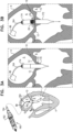
- Figs. 21A-C show implant 420 disposed at native valve 10, when the anatomy of the native valve (e.g., the annulus and/or leaflets) are uneven with respect to the implant.
- the anatomy itself may be particularly uneven, or the implant may have been implanted at a sub-optimal angle with respect to the anatomy.
- outer portion 504 fills, in each zone, according to the mechanical constraints of that region ( Figs. 21B-C ).
- outer portion 504 inflates with blood until space between upstream support portion 40 and the anatomy (e.g., annulus or leaflet tissue) is filled, and the anatomy resists further inflation of the outer portion ( Fig. 21B ).
- outer portion 504 continues to inflate with blood because, in this zone, the space between the upstream support portion and the anatomy is larger ( Fig. 21C ). In this way, it is hypothesized by the inventors that implant 420 advantageously adapts to the native anatomy, providing improved paravalvular sealing.
- At least one coagulation component 530 is disposed within outer portion 504, and is configured to promote blood coagulation within the outer portion.
- coagulation component 530 is annular and, within outer portion 504, circumscribes the longitudinal axis of the implant.
- coagulation component 530 comprises a fabric (e.g., comprising polyethylene terephthalate).
- coagulation component 530 comprises polytetrafluoroethylene (e.g., expanded polytetrafluoroethylene), e.g., in the form of a membrane or ribbon.
- coagulation component 530 comprises a metallic (e.g., nitinol or stainless steel) wire, membrane, or mesh, covered by a fabric or expanded polytetrafluoroethylene.
- coagulation component comprises a coagulation-inducing drug coated thereon or embedded therein (e.g., within a fabric).
- coagulation component 530 comprises pericardial tissue (e.g., bovine or porcine).
- the scope of the invention includes using one or more of the apparatus and techniques described in this patent application in combination with one or more of the apparatus and techniques described in one or more of the following documents, each of which is incorporated herein by reference:
Landscapes
- Health & Medical Sciences (AREA)
- Cardiology (AREA)
- Engineering & Computer Science (AREA)
- Biomedical Technology (AREA)
- Heart & Thoracic Surgery (AREA)
- Transplantation (AREA)
- Oral & Maxillofacial Surgery (AREA)
- Vascular Medicine (AREA)
- Life Sciences & Earth Sciences (AREA)
- Animal Behavior & Ethology (AREA)
- General Health & Medical Sciences (AREA)
- Public Health (AREA)
- Veterinary Medicine (AREA)
- Prostheses (AREA)
Applications Claiming Priority (6)
| Application Number | Priority Date | Filing Date | Title |
|---|---|---|---|
| US15/956,956 US10575948B2 (en) | 2017-08-03 | 2018-04-19 | Prosthetic heart valve |
| PCT/IL2018/050725 WO2019026059A1 (en) | 2017-08-03 | 2018-07-04 | PROSTHETIC CARDIAC VALVE |
| US16/135,979 US11304805B2 (en) | 2017-09-19 | 2018-09-19 | Prosthetic valve with inflatable cuff configured to fill a volume between atrial and ventricular tissue anchors |
| US16/135,969 US11819405B2 (en) | 2017-09-19 | 2018-09-19 | Prosthetic valve with inflatable cuff configured for radial extension |
| EP19704053.8A EP3781085B1 (de) | 2018-04-19 | 2019-02-06 | Herzklappenprothese mit beutel |
| PCT/IL2019/050142 WO2019202579A1 (en) | 2018-04-19 | 2019-02-06 | Prosthetic heart valve with pouch |
Related Parent Applications (1)
| Application Number | Title | Priority Date | Filing Date |
|---|---|---|---|
| EP19704053.8A Division EP3781085B1 (de) | 2018-04-19 | 2019-02-06 | Herzklappenprothese mit beutel |
Publications (2)
| Publication Number | Publication Date |
|---|---|
| EP4494607A2 true EP4494607A2 (de) | 2025-01-22 |
| EP4494607A3 EP4494607A3 (de) | 2025-04-16 |
Family
ID=68238832
Family Applications (2)
| Application Number | Title | Priority Date | Filing Date |
|---|---|---|---|
| EP24218125.3A Pending EP4494607A3 (de) | 2018-04-19 | 2019-02-06 | Herzklappenprothese mit beutel |
| EP19704053.8A Active EP3781085B1 (de) | 2018-04-19 | 2019-02-06 | Herzklappenprothese mit beutel |
Family Applications After (1)
| Application Number | Title | Priority Date | Filing Date |
|---|---|---|---|
| EP19704053.8A Active EP3781085B1 (de) | 2018-04-19 | 2019-02-06 | Herzklappenprothese mit beutel |
Country Status (5)
| Country | Link |
|---|---|
| EP (2) | EP4494607A3 (de) |
| CN (2) | CN118662279A (de) |
| CA (1) | CA3096002A1 (de) |
| ES (1) | ES3006111T3 (de) |
| WO (1) | WO2019202579A1 (de) |
Families Citing this family (24)
| Publication number | Priority date | Publication date | Assignee | Title |
|---|---|---|---|---|
| US8870950B2 (en) | 2009-12-08 | 2014-10-28 | Mitral Tech Ltd. | Rotation-based anchoring of an implant |
| US20110224785A1 (en) | 2010-03-10 | 2011-09-15 | Hacohen Gil | Prosthetic mitral valve with tissue anchors |
| US9763657B2 (en) | 2010-07-21 | 2017-09-19 | Mitraltech Ltd. | Techniques for percutaneous mitral valve replacement and sealing |
| US11653910B2 (en) | 2010-07-21 | 2023-05-23 | Cardiovalve Ltd. | Helical anchor implantation |
| EP2739214B1 (de) | 2011-08-05 | 2018-10-10 | Cardiovalve Ltd | Perkutaner mitralklappenersatz und versiegelung |
| WO2013021374A2 (en) | 2011-08-05 | 2013-02-14 | Mitraltech Ltd. | Techniques for percutaneous mitral valve replacement and sealing |
| US8852272B2 (en) | 2011-08-05 | 2014-10-07 | Mitraltech Ltd. | Techniques for percutaneous mitral valve replacement and sealing |
| US9681952B2 (en) | 2013-01-24 | 2017-06-20 | Mitraltech Ltd. | Anchoring of prosthetic valve supports |
| US10524910B2 (en) | 2014-07-30 | 2020-01-07 | Mitraltech Ltd. 3 Ariel Sharon Avenue | Articulatable prosthetic valve |
| ES2978714T3 (es) | 2015-02-05 | 2024-09-18 | Cardiovalve Ltd | Válvula protésica con marcos de deslizamiento axial |
| US10531866B2 (en) | 2016-02-16 | 2020-01-14 | Cardiovalve Ltd. | Techniques for providing a replacement valve and transseptal communication |
| US20190231525A1 (en) | 2016-08-01 | 2019-08-01 | Mitraltech Ltd. | Minimally-invasive delivery systems |
| CA3031187A1 (en) | 2016-08-10 | 2018-02-15 | Cardiovalve Ltd. | Prosthetic valve with concentric frames |
| US12064347B2 (en) | 2017-08-03 | 2024-08-20 | Cardiovalve Ltd. | Prosthetic heart valve |
| US11246704B2 (en) | 2017-08-03 | 2022-02-15 | Cardiovalve Ltd. | Prosthetic heart valve |
| US11793633B2 (en) | 2017-08-03 | 2023-10-24 | Cardiovalve Ltd. | Prosthetic heart valve |
| US10888421B2 (en) | 2017-09-19 | 2021-01-12 | Cardiovalve Ltd. | Prosthetic heart valve with pouch |
| US12458493B2 (en) | 2017-09-19 | 2025-11-04 | Cardiovalve Ltd. | Prosthetic heart valve and delivery systems and methods |
| US9895226B1 (en) | 2017-10-19 | 2018-02-20 | Mitral Tech Ltd. | Techniques for use with prosthetic valve leaflets |
| GB201720803D0 (en) | 2017-12-13 | 2018-01-24 | Mitraltech Ltd | Prosthetic Valve and delivery tool therefor |
| GB201800399D0 (en) | 2018-01-10 | 2018-02-21 | Mitraltech Ltd | Temperature-control during crimping of an implant |
| US10779946B2 (en) | 2018-09-17 | 2020-09-22 | Cardiovalve Ltd. | Leaflet-testing apparatus |
| GB201901887D0 (en) | 2019-02-11 | 2019-04-03 | Cardiovalve Ltd | Device for conditioning ex vivo pericardial tissue |
| US12357459B2 (en) | 2020-12-03 | 2025-07-15 | Cardiovalve Ltd. | Transluminal delivery system |
Citations (3)
| Publication number | Priority date | Publication date | Assignee | Title |
|---|---|---|---|---|
| WO2016125160A1 (en) | 2015-02-05 | 2016-08-11 | Mitraltech Ltd. | Prosthetic valve with axially-sliding frames |
| US20180014930A1 (en) | 2015-02-05 | 2018-01-18 | Mitraltech Ltd. | Prosthetic Valve with Axially-Sliding Frames |
| WO2018029680A1 (en) | 2016-08-10 | 2018-02-15 | Mitraltech Ltd. | Prosthetic valve with concentric frames |
Family Cites Families (6)
| Publication number | Priority date | Publication date | Assignee | Title |
|---|---|---|---|---|
| JP5379852B2 (ja) * | 2008-07-15 | 2013-12-25 | セント ジュード メディカル インコーポレイテッド | 潰れ可能かつ再膨張可能な人工心臓弁カフ設計および補完的技術出願 |
| US10321986B2 (en) * | 2012-12-19 | 2019-06-18 | W. L. Gore & Associates, Inc. | Multi-frame prosthetic heart valve |
| CN105142573B (zh) * | 2013-03-12 | 2017-03-15 | 美敦力公司 | 心脏瓣膜假体 |
| EP3013281B1 (de) * | 2013-06-25 | 2018-08-15 | Tendyne Holdings, Inc. | Thrombusmanagement und strukturelle konformitätsmerkmale für herzklappenprothesen |
| US10117744B2 (en) * | 2015-08-26 | 2018-11-06 | Edwards Lifesciences Cardiaq Llc | Replacement heart valves and methods of delivery |
| US10639143B2 (en) * | 2016-08-26 | 2020-05-05 | Edwards Lifesciences Corporation | Multi-portion replacement heart valve prosthesis |
-
2019
- 2019-02-06 EP EP24218125.3A patent/EP4494607A3/de active Pending
- 2019-02-06 CN CN202410892113.0A patent/CN118662279A/zh active Pending
- 2019-02-06 CN CN201980023291.7A patent/CN111970994B/zh active Active
- 2019-02-06 ES ES19704053T patent/ES3006111T3/es active Active
- 2019-02-06 WO PCT/IL2019/050142 patent/WO2019202579A1/en not_active Ceased
- 2019-02-06 CA CA3096002A patent/CA3096002A1/en active Pending
- 2019-02-06 EP EP19704053.8A patent/EP3781085B1/de active Active
Patent Citations (5)
| Publication number | Priority date | Publication date | Assignee | Title |
|---|---|---|---|---|
| WO2016125160A1 (en) | 2015-02-05 | 2016-08-11 | Mitraltech Ltd. | Prosthetic valve with axially-sliding frames |
| US20170333187A1 (en) | 2015-02-05 | 2017-11-23 | Mitraltech Ltd. | Techniques for deployment of a prosthetic valve |
| US20180014930A1 (en) | 2015-02-05 | 2018-01-18 | Mitraltech Ltd. | Prosthetic Valve with Axially-Sliding Frames |
| US9974651B2 (en) | 2015-02-05 | 2018-05-22 | Mitral Tech Ltd. | Prosthetic valve with axially-sliding frames |
| WO2018029680A1 (en) | 2016-08-10 | 2018-02-15 | Mitraltech Ltd. | Prosthetic valve with concentric frames |
Also Published As
| Publication number | Publication date |
|---|---|
| ES3006111T3 (en) | 2025-03-17 |
| CA3096002A1 (en) | 2019-10-24 |
| EP4494607A3 (de) | 2025-04-16 |
| CN118662279A (zh) | 2024-09-20 |
| EP3781085A1 (de) | 2021-02-24 |
| CN111970994A (zh) | 2020-11-20 |
| CN111970994B (zh) | 2024-07-26 |
| WO2019202579A1 (en) | 2019-10-24 |
| EP3781085B1 (de) | 2025-01-01 |
Similar Documents
| Publication | Publication Date | Title |
|---|---|---|
| EP3781085B1 (de) | Herzklappenprothese mit beutel | |
| US10888421B2 (en) | Prosthetic heart valve with pouch | |
| CA3071090C (en) | PROSTHETIC HEART VALVE | |
| US12090048B2 (en) | Prosthetic heart valve | |
| US11246704B2 (en) | Prosthetic heart valve | |
| US10575948B2 (en) | Prosthetic heart valve | |
| US10537426B2 (en) | Prosthetic heart valve | |
| US12409031B2 (en) | Prosthetic valve having a multi-part frame | |
| US12232958B2 (en) | Prosthetic heart valve | |
| EP2155114B1 (de) | Herzklappenprothesen | |
| US10433956B2 (en) | Mitral prosthesis and methods for implantation | |
| EP2870946B1 (de) | Dichtungsmechanismus für paravalvuläre Lecks | |
| US8734506B2 (en) | Aortic annuloplasty ring | |
| CN117752469A (zh) | 心脏瓣膜假体 | |
| HK40095462A (zh) | 人工心脏瓣膜 |
Legal Events
| Date | Code | Title | Description |
|---|---|---|---|
| PUAI | Public reference made under article 153(3) epc to a published international application that has entered the european phase |
Free format text: ORIGINAL CODE: 0009012 |
|
| STAA | Information on the status of an ep patent application or granted ep patent |
Free format text: STATUS: THE APPLICATION HAS BEEN PUBLISHED |
|
| AC | Divisional application: reference to earlier application |
Ref document number: 3781085 Country of ref document: EP Kind code of ref document: P |
|
| AK | Designated contracting states |
Kind code of ref document: A2 Designated state(s): AL AT BE BG CH CY CZ DE DK EE ES FI FR GB GR HR HU IE IS IT LI LT LU LV MC MK MT NL NO PL PT RO RS SE SI SK SM TR |
|
| PUAL | Search report despatched |
Free format text: ORIGINAL CODE: 0009013 |
|
| AK | Designated contracting states |
Kind code of ref document: A3 Designated state(s): AL AT BE BG CH CY CZ DE DK EE ES FI FR GB GR HR HU IE IS IT LI LT LU LV MC MK MT NL NO PL PT RO RS SE SI SK SM TR |
|
| RIC1 | Information provided on ipc code assigned before grant |
Ipc: A61F 2/24 20060101AFI20250311BHEP |
|
| STAA | Information on the status of an ep patent application or granted ep patent |
Free format text: STATUS: REQUEST FOR EXAMINATION WAS MADE |
|
| 17P | Request for examination filed |
Effective date: 20251015 |