EP4494456A1 - Reforestation planning device, reforestation system, and reforestation planning method - Google Patents
Reforestation planning device, reforestation system, and reforestation planning method Download PDFInfo
- Publication number
- EP4494456A1 EP4494456A1 EP23791856.0A EP23791856A EP4494456A1 EP 4494456 A1 EP4494456 A1 EP 4494456A1 EP 23791856 A EP23791856 A EP 23791856A EP 4494456 A1 EP4494456 A1 EP 4494456A1
- Authority
- EP
- European Patent Office
- Prior art keywords
- reforestation
- area
- machine
- planting
- gradient
- Prior art date
- Legal status (The legal status is an assumption and is not a legal conclusion. Google has not performed a legal analysis and makes no representation as to the accuracy of the status listed.)
- Pending
Links
Images




Classifications
-
- G—PHYSICS
- G06—COMPUTING OR CALCULATING; COUNTING
- G06Q—INFORMATION AND COMMUNICATION TECHNOLOGY [ICT] SPECIALLY ADAPTED FOR ADMINISTRATIVE, COMMERCIAL, FINANCIAL, MANAGERIAL OR SUPERVISORY PURPOSES; SYSTEMS OR METHODS SPECIALLY ADAPTED FOR ADMINISTRATIVE, COMMERCIAL, FINANCIAL, MANAGERIAL OR SUPERVISORY PURPOSES, NOT OTHERWISE PROVIDED FOR
- G06Q50/00—Information and communication technology [ICT] specially adapted for implementation of business processes of specific business sectors, e.g. utilities or tourism
- G06Q50/02—Agriculture; Fishing; Forestry; Mining
-
- A—HUMAN NECESSITIES
- A01—AGRICULTURE; FORESTRY; ANIMAL HUSBANDRY; HUNTING; TRAPPING; FISHING
- A01G—HORTICULTURE; CULTIVATION OF VEGETABLES, FLOWERS, RICE, FRUIT, VINES, HOPS OR SEAWEED; FORESTRY; WATERING
- A01G23/00—Forestry
-
- G—PHYSICS
- G05—CONTROLLING; REGULATING
- G05D—SYSTEMS FOR CONTROLLING OR REGULATING NON-ELECTRIC VARIABLES
- G05D1/00—Control of position, course, altitude or attitude of land, water, air or space vehicles, e.g. using automatic pilots
- G05D1/60—Intended control result
- G05D1/648—Performing a task within a working area or space, e.g. cleaning
- G05D1/6484—Performing a task within a working area or space, e.g. cleaning by taking into account parameters or characteristics of the working area or space, e.g. size or shape
-
- Y—GENERAL TAGGING OF NEW TECHNOLOGICAL DEVELOPMENTS; GENERAL TAGGING OF CROSS-SECTIONAL TECHNOLOGIES SPANNING OVER SEVERAL SECTIONS OF THE IPC; TECHNICAL SUBJECTS COVERED BY FORMER USPC CROSS-REFERENCE ART COLLECTIONS [XRACs] AND DIGESTS
- Y02—TECHNOLOGIES OR APPLICATIONS FOR MITIGATION OR ADAPTATION AGAINST CLIMATE CHANGE
- Y02A—TECHNOLOGIES FOR ADAPTATION TO CLIMATE CHANGE
- Y02A40/00—Adaptation technologies in agriculture, forestry, livestock or agroalimentary production
- Y02A40/10—Adaptation technologies in agriculture, forestry, livestock or agroalimentary production in agriculture
- Y02A40/22—Improving land use; Improving water use or availability; Controlling erosion
-
- Y—GENERAL TAGGING OF NEW TECHNOLOGICAL DEVELOPMENTS; GENERAL TAGGING OF CROSS-SECTIONAL TECHNOLOGIES SPANNING OVER SEVERAL SECTIONS OF THE IPC; TECHNICAL SUBJECTS COVERED BY FORMER USPC CROSS-REFERENCE ART COLLECTIONS [XRACs] AND DIGESTS
- Y02—TECHNOLOGIES OR APPLICATIONS FOR MITIGATION OR ADAPTATION AGAINST CLIMATE CHANGE
- Y02P—CLIMATE CHANGE MITIGATION TECHNOLOGIES IN THE PRODUCTION OR PROCESSING OF GOODS
- Y02P60/00—Technologies relating to agriculture, livestock or agroalimentary industries
- Y02P60/40—Afforestation or reforestation
Definitions
- the present disclosure relates to a reforestation planning device, a reforestation system, and a reforestation planning method.
- Patent Document 1 discloses a technology for recognizing a terrain of a work site based on images of the work site acquired by an unmanned aircraft and planning the movement path of a forestry machine for harvest of timber.
- An object of the present disclosure is to provide a reforestation planning device, a reforestation system, and a reforestation planning method for establishing a reforestation plan in consideration of future harvest according to the terrain of a target area.
- a reforestation planning device includes: a data acquisition unit configured to acquire terrain data representing a terrain of a target area; an area specification unit configured to specify a first area having a gradient less than a first gradient threshold value from the target area based on the terrain data; and a reforestation instruction unit configured to transmit a reforestation instruction signal, which is a signal for instructing planting of a plant body in a reforestation area consisting of the first area, including at least one of the reforestation area or a traveling route in the reforestation area for planting the plant body by a reforestation machine.
- a reforestation instruction signal which is a signal for instructing planting of a plant body in a reforestation area consisting of the first area, including at least one of the reforestation area or a traveling route in the reforestation area for planting the plant body by a reforestation machine.
- FIG. 1 is a schematic diagram showing a reforestation system 1 according to a first embodiment.
- the reforestation system 1 generates a reforestation plan for a target area T based on terrain data of the target area T and executes a reforestation work in accordance with the reforestation plan.
- the reforestation system 1 includes a reforestation machine 10, an earthwork machine 30, and a reforestation planning device 50.
- the reforestation machine 10 is a vehicle having a function of planting a plant body into soil.
- the earthwork machine 30 is a vehicle having a function of excavating earth.
- the reforestation machine 10 and the earthwork machine 30 according to the first embodiment are autonomously driven.
- the reforestation machine 10 and the earthwork machine 30 may not be autonomously driven.
- the reforestation planning device 50 generates a reforestation plan for a target area based on terrain data of the target area and transmits an instruction signal to the reforestation machine 10 and the earthwork machine 30.
- the reforestation machine 10 and the earthwork machine 30 operate based on the instruction signal received from the reforestation planning device 50.
- the reforestation planning device 50, the reforestation machine 10, and the earthwork machine 30 are connected to each other via a communication network N such as the Internet.
- the reforestation planning device 50 may be provided remotely from the reforestation machine 10 and the earthwork machine 30.
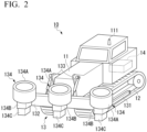
- FIG. 2 is an external view of a reforestation machine 10 according to the first embodiment.
- the reforestation machine 10 includes a vehicle body 11, a traveling device 12, a planting device 13, and a control device 14.
- the reforestation machine 10 may be, for example, a bulldozer in which a blade is replaced with the planting device 13.
- the reforestation machine 10 may use the planting device 13 as an attachment of a hydraulic excavator.
- the traveling device 12 supports the vehicle body 11 to be capable of traveling.
- the traveling device 12 is a continuous track driven by a power of an engine. Meanwhile, in other embodiments, the traveling device 12 may include wheels and legs driven by the power of the engine.
- a position measurement device 111 for measuring a position of the vehicle body 11 is provided in the vehicle body 11.
- the position measurement device 111 includes an antenna that receives a position measurement signal from a GNSS, and measures the position of the vehicle body 11 based on the position measurement signal received via the antenna.
- the position measurement device 111 outputs position data indicating the measured position to the control device 14.
- the position of the vehicle body 11 is represented by a two-dimensional or three-dimensional global coordinate system.
- the planting device 13 plants the plant body into the soil.
- the planting device 13 is provided in front of the vehicle body 11.
- the planting device 13 may be disposed behind the vehicle body 11.
- the planting device 13 includes an arm 131, a frame 132, a hydraulic cylinder 133, and three planting portions 134.
- the number of planting portions 134 is not limited to three and may be less than three or more than three.
- the arm 131 is attached to a frame portion of the traveling device 12 and supports the planting device 13 to be capable of lifting and lowering.
- the frame 132 is attached to a distal end of the arm 131 and supports three planting portions 134.
- the hydraulic cylinder 133 is provided between a front portion of the vehicle body 11 and the frame 132, and lifts and lowers the frame 132 by expansion and contraction.
- the three planting portions 134 are arranged side by side in the width direction of the reforestation machine 10.
- the width direction of the reforestation machine 10 is a direction orthogonal to a traveling direction of the reforestation machine 10.
- the planting portion 134 includes a plant body holding unit 134A, a main body portion 134B, and an expansion and contraction portion 134C.
- the main body portion 134B is attached to the frame 132.
- the plant body holding unit 134A is provided on an upper portion of the main body portion 134B.
- the expansion and contraction portion 134C protrudes from a lower portion of the main body portion 134B.
- the plant body holding unit 134A holds the plant body to be planted into the soil.
- the plant body is, for example, a seed or a seedling of a tree.
- the plant body holding unit 134A may hold a plurality of types of plant bodies.
- the plant body holding unit 134A may hold a plant body suitable for wood and a plant body constituting vegetation of the target area T.
- the main body portion 134B takes out the plant body from the plant body holding unit 134A and transfers the plant body to a distal end of the expansion and contraction portion 134C.
- the expansion and contraction portion 134C expands while holding the plant body at the distal end portion to plant the plant body into the soil.
- the expansion and contraction portion 134C is expanded and contracted by, for example, a hydraulic cylinder. By expanding and contracting the expansion and contraction portion 134C, the plant body can be planted into the soil even when the soil is not flat and the distance between the main body portion 134B and the soil changes.
- the control device 14 generates a driving signal for driving the traveling device 12 and the planting device 13, and controls actuators of the traveling device 12 and the planting device 13.
- the control device 14 includes a communication device that performs communication with the reforestation planning device 50 via the communication network N.
- the control device 14 controls the traveling device 12 and the planting device 13 based on the instruction signal received from the reforestation planning device 50 via the communication network N and the position data acquired from the position measurement device 111.
- the instruction signal received from the reforestation planning device 50 includes a map of the target area T, a traveling route of the reforestation machine 10, and information indicating the type of plant body, a planting range, and a planting interval.
- the control device 14 drives the traveling device 12 such that the reforestation machine 10 moves to the starting point of the traveling route based on the position data and the traveling route, and drives the traveling device 12 such that the reforestation machine 10 moves along the traveling route after reaching the starting point of the traveling route.
- the control device 14 determines whether the reforestation machine 10 is located within the planting range based on the position data, and in a case in which the reforestation machine 10 is located within the planting range, drives the planting device 13 to plant the plant body at the planting interval.
- control device 14 may determine the timing for performing the next planting based on the speed of the traveling device 12 and the planting interval, or may determine the position for performing the next planting based on the distance from the position indicated by the position data of the previous planting. The control device 14 does not drive the planting device 13 when the reforestation machine 10 is not located within the planting range.
- FIG. 3 is an external view of the earthwork machine 30 according to the first embodiment.
- the earthwork machine 30 may be, for example, a bulldozer.
- the earthwork machine 30 may be a hydraulic excavator or a wheel loader.
- the earthwork machine 30 includes a vehicle body 31, a traveling device 32, work equipment 33, and a control device 34.
- the traveling device 32 supports the vehicle body 31 to be capable of traveling.
- the traveling device 32 is a continuous track driven by a power of an engine. Meanwhile, in other embodiments, the traveling device 32 may include wheels driven by the power of the engine.
- a position measurement device 311 for measuring a position of the vehicle body 31 is provided in the vehicle body 31.
- the position measurement device 311 includes an antenna that receives a position measurement signal from a GNSS, and measures the position of the vehicle body 31 based on the position measurement signal received via the antenna.
- the position measurement device 311 outputs position data indicating the measured position to the control device 34.
- the position of the vehicle body 31 is represented by a three-dimensional global coordinate system.
- the work equipment 33 is used to excavate and transport an excavation target such as earth.
- the work equipment 33 is provided at a front portion of the vehicle body 31.
- the work equipment 33 includes a lift frame 331, a blade 332, and a lift cylinder 333.
- a proximal end portion of the lift frame 331 is attached to a side surface of the vehicle body 31 through a pin extending in a vehicle width direction.
- a distal end portion of the lift frame 331 is attached to a back surface of the blade 332 through a spherical joint.
- the blade 332 is supported to be movable in an up-down direction with respect to the vehicle body 31.
- a blade edge 332e is provided at a lower end portion of the blade 332.
- the lift cylinder 333 is a hydraulic cylinder.
- a proximal end portion of the lift cylinder 333 is attached to the side surface of the vehicle body 31.
- a distal end portion of the lift cylinder 333 is attached to the lift frame 331.
- the lift frame 331 and the blade 332 are lifted and lowered by the lift cylinder 333 being expanded and contracted by hydraulic oil.
- the lift cylinder 333 is provided with a stroke sensor 334 that measures a stroke amount of the lift cylinder 333.
- the stroke amount measured by the stroke sensor 334 can be converted into a position of the blade edge 332e with the vehicle body 31 as a reference.
- a rotation angle of the lift frame 331 is calculated based on the stroke amount of the lift cylinder 333. Since the shapes of the lift frame 331 and the blade 332 are known, the position of the blade edge 332e of the blade 332 can be specified from the rotation angle of the lift frame 331.
- the earthwork machine 30 may detect the rotation angle with another sensor such as an encoder.
- the control device 34 generates a driving signal for driving the traveling device 32 and the work equipment 33, and controls actuators of the traveling device 32 and the work equipment 33.
- the control device 34 includes a communication device that performs communication with the reforestation planning device 50 via the communication network N.
- the control device 14 controls the traveling device 32 and the work equipment 33 based on the instruction signal received from the reforestation planning device 50 via the communication network N, the position data measured by the position measurement device 311, and the position of the blade edge 332e converted from measurement data of the stroke sensor 334.
- the instruction signal received from the reforestation planning device 50 includes information indicating a current state terrain of the target area T and a design plane of the target area T.
- the control device 14 drives the traveling device 12 such that the traveling device 12 moves toward a position where the difference in height between the current state terrain and the design plane exceeds a predetermined threshold value, based on the position data.
- the control device 14 determines the target height of the blade edge 332e in accordance with the difference in height between the current state terrain and the design plane at the current position indicated by the position data, and drives the lift cylinder 333 such that a height of the blade edge 332e reaches the target height.
- the control device 34 repeatedly executes the above control while updating the current state terrain based on the height of the blade edge 332e during traveling.
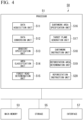
- FIG. 4 is a schematic block diagram showing a configuration of the reforestation planning device 50 according to the first embodiment.
- the reforestation planning device 50 is a computer including a processor 51, a main memory 53, a storage 55, and an interface 57.
- the storage 55 stores a program.
- the processor 51 reads out the program from the storage 55, loads the program in the main memory 53, and executes a process according to the program.
- the reforestation planning device 50 may include a custom large scale integrated circuit (LSI), such as a programmable logic device (PLD), in addition to the above-described configuration or instead of the above-described configuration.
- LSI large scale integrated circuit
- PLD programmable logic device
- a programmable array logic (PAL), a generic array logic (GAL), a complex programmable logic device (CPLD), and a field programmable gate array (FPGA) are exemplary examples of the PLD.
- some or all of the functions to be realized by the processor 51 may be realized by the integrated circuit.
- the integrated circuit is also included in the example of the processor.
- the reforestation planning device 50 is connected to the communication network N via the interface 57.
- the reforestation planning device 50 is connected to an input/output device (not shown) via the interface 57.
- a hard disk drive (HDD), a solid state drive (SSD), a non-volatile memory, and the like are exemplary examples of the storage 55.
- the storage 55 may be an internal medium directly connected to a bus of the reforestation planning device 50, or may be an external medium connected to the reforestation planning device 50 via the interface 57.
- the storage 55 is a non-transitory tangible storage medium.
- the processor 51 functions as a data acquisition unit 511, a data conversion unit 512, a gradient specification unit 513, an area classification unit 514, an earthwork area specification unit 515, a design plane generation unit 516, an earthwork instruction unit 517, a reforestation area determination unit 518, a forest road determination unit 519, and a reforestation instruction unit 520 by executing the program.
- the data acquisition unit 511 acquires current state terrain data obtained from the measurement of the terrain of the target area T.
- the current state terrain data is represented by, for example, three-dimensional data such as point cloud data.
- the current state terrain data may be generated based on, for example, the history of position information of a robot that travels over the target area T. In this case, the height of the ground can be specified even when trees are growing in the target area T.
- the current state terrain data may be measured by a drone equipped with LiDAR or a stereo camera. When trees are not growing in the target area T, such as after the harvest in the target area T, the data measured by the drone can be used directly as the current state terrain data.
- the data acquisition unit 511 acquires the current state terrain data from, for example, an external memory, a robot body, or a drone body connected to the interface 57 by wired or wireless method.
- the data conversion unit 512 converts the current state terrain data into mesh data.
- the mesh data is data in which various types of data, such as height data, are stored in each mesh (lattice) that divides the terrain using a plane lattice extending horizontally.
- the data conversion unit 512 converts, for example, with respect to each mesh, the point cloud data into the mesh data by setting the average value of the heights of points in the vicinity of mesh in the point cloud data as the height of the mesh.
- the lattice of the mesh data may be a plane-fillable polygon other than a square, such as an equilateral triangle or a regular hexagon.
- the reforestation planning device 50 may not include the data conversion unit 512.
- the gradient specification unit 513 specifies a gradient in each mesh indicated by the mesh data converted by the data conversion unit 512.
- the gradient specification unit 513 can specify the gradient, for example, by obtaining a normal vector (vertex normal) of the mesh.
- the normal vector of the mesh can be obtained as follows.
- the gradient specification unit 513 calculates a normal vector of a line segment connecting the mesh, which is the calculation target of the normal vector, and another mesh adjacent to the mesh.
- the normal vector of the mesh to be calculated can be obtained by obtaining a vector of the sum of the normal vectors of each of sides and normalizing the obtained vector. It can be seen that the gradient of the ground represented by the mesh is smaller as the angle between the normal vector and the vertical line (normal vector of horizontal plane) becomes smaller.
- FIG. 5 is a diagram showing an example of the area of the target area T in the first embodiment.
- the area classification unit 514 classifies the target area T into a plurality of areas consisting of a first area A1 where a gradient is less than a first gradient threshold value and a second area A2 where a gradient is equal to or greater than the first gradient threshold value, based on the gradient of each mesh specified by the gradient specification unit 513.
- the first area A1 is an area where the gradient is small, which makes harvest by a forestry machine such as a feller buncher relatively easy.
- the second area A2 is an area where the gradient is large, which makes harvest by the forestry machine relatively difficult.
- the area classification unit 514 divides each mesh into a mesh where a gradient is equal to or greater than the first gradient threshold value and a mesh where a gradient is less than the first gradient threshold value.
- the area classification unit 514 defines a continuous ground area filled with the mesh where the gradient is equal to or greater than the first gradient threshold value as the first area A1 and defines a continuous ground area filled with the mesh where the gradient is less than the first gradient threshold value as the second area A2.
- the area classification unit 514 can classify the area using a labeling algorithm or the like on a binarized image.
- the area classification unit 514 may regard the second area A2 surrounded by the first area A1 and having a small number of meshes (equal to or less than a predetermined number) as belonging to the first area A1. Similarly, the area classification unit 514 may regard the first area A1 surrounded by the second area A2 and having a small number of meshes (equal to or less than a predetermined number) as belonging to the second area A2.
- the area classification unit 514 may apply other algorithms for area classification.
- the area classification unit 514 specifies a largest area classified into the first area A1 among the plurality of areas as a main area A1m, which is the reforestation target.
- the area classification unit 514 may define an area, which is classified as the first area A1, closest to the existing road among the plurality of areas as the main area A1m.
- the main area A1m not only the main area A1m but also other first areas A1 may be the reforestation target.
- the area classification unit 514 is an example of an area specification unit that specifies the first area A1 and the second area A2 from the target area T.
- the earthwork area specification unit 515 specifies a portion of the second area A2 where a gradient is less than a second gradient threshold value as a third area A3.
- the second gradient threshold value is larger than the first gradient threshold value.
- the third area A3 is an area where it is practically possible to reduce the gradient to be less than the first gradient threshold value through construction by the earthwork machine 30.
- the earthwork area specification unit 515 defines a continuous ground portion of the second area A2 that is adjacent to the first area A1 and is filled with a mesh where a gradient is less than the second gradient threshold value as the third area A3. That is, even if the gradient is less than the second gradient threshold value, in a case in which the first area A1 is not a continuous ground after the construction, it is difficult to move the forestry machine, and thus the first area A1 is not a construction target.
- the design plane generation unit 516 generates the design plane of the third area A3 such that the gradient of the third area A3 is less than the first gradient threshold value and the amount of earth to be worked is minimized.
- the design plane generation unit 516 may generate the design plane such that all the meshes are less than the first gradient threshold value for at least the third area A3 and the amount of change (excavation amount) from the current state terrain is minimized.
- the design plane generation unit 516 may generate the design plane such that all the meshes are less than the first gradient threshold value for at least the third area A3 and the sum of the excavation amount and the embankment amount approaches zero.
- the design plane generation unit 516 may generate the design plane of the third area A3 such that the area of the area where the gradient is less than the first gradient threshold value after the construction is maximized.
- the design plane generation unit 516 may generate the design plane such that all the meshes are less than the first gradient threshold value for at least the third area A3, and may further generate the design plane such that at least some of the meshes are less than the first gradient threshold value by embanking the earth to be excavated in the third area A3 for the second area A2 adjacent to the third area A3.
- the design plane is a plane showing a target terrain of the earthwork machine 30 after the construction.
- the earthwork instruction unit 517 transmits, to the earthwork machine 30, an earthwork instruction signal for instructing the construction of the third area A3 in accordance with the design plane.
- the earthwork instruction signal includes the mesh data of the current state terrain generated by the data conversion unit 512 and design plane data representing the design plane generated by the design plane generation unit 516.
- the earthwork instruction signal may not include the mesh data of the current state terrain and may only include the design plane data.
- the reforestation area determination unit 518 determines the continuous ground area consisting of the main area A1m, the third area A3, and the first area A1 (subarea A1s) adjacent to the third area A3 as the reforestation area.
- the subarea A1s is the first area A1 where the third area A3 is interposed between the subarea A1s and the main area A1m.
- the reforestation area consisting of the main area A1m, the third area A3, and the subarea A1s is a continuous ground area that is less than the first gradient threshold value.
- the forest road determination unit 519 disposes a forest road area A1r for forming a forest road for the forestry machine to pass through in the reforestation area determined by the reforestation area determination unit 518.
- the forest road area A1r is a band-shaped area having a predetermined width, and is provided such that the forestry machine is movable over the entire reforestation area.
- the forest road determination unit 519 may dispose the forest road area A1r to pass through the center of the reforestation area.
- the forest road determination unit 519 can determine the forest road area A1r using a thinning algorithm or the like.
- the reforestation planning device 50 may not include the forest road determination unit 519.
- the reforestation instruction unit 520 transmits, to the reforestation machine 10, a reforestation instruction signal for instructing planting of a plant body in an area of the reforestation area excluding the forest road area A1r.
- the reforestation instruction signal includes the mesh data of the target area T, the traveling route of the reforestation machine 10, and information indicating the type of plant body, the planting depth, the planting range, the planting interval, and the like.
- the traveling route is determined based on the reforestation area and the width of the reforestation machine 10. For example, the reforestation instruction unit 520 determines the traveling route according to the following procedure.
- the reforestation instruction unit 520 sets a plurality of reforestation target lines extending parallel with each other in the area of the reforestation area excluding the forest road area A1r.
- An interval between adjacent reforestation target lines is equal to an interval between the planting portions 134 of the reforestation machine 10.
- the reforestation instruction unit 520 determines the center of the reforestation target line corresponding to each set as the traveling route of the reforestation machine 10 by grouping three adjacent reforestation target lines into one set.
- the planting interval is an interval at which the plant body is planted in a traveling direction of the reforestation machine 10.
- the planting interval may be equal to the interval of the planting portions 134, or may be determined by a user.
- the traveling route may be set by the user based on the reforestation area, or may be automatically set by the reforestation planning device based on the reforestation area.
- the reforestation instruction unit 520 transmits, to an area other than the reforestation area, a reforestation instruction signal for instructing the planting of the plant body constituting the vegetation according to an environment of the target area T.
- the reforestation instruction unit 520 may store a table in which information representing the environment, for example, air temperature, precipitation amount, and altitude, is associated with the plant body constituting the vegetation in the environment in advance, and may specify the plant body constituting the vegetation from the environment of the target area.
- the plant body constituting the vegetation according to the environment may be determined by an expert or the like.
- FIG. 6 is a flowchart showing the process of the reforestation planning device 50 according to the first embodiment.
- the user activates the reforestation planning device 50 and inputs the current state terrain data of the target area T to the reforestation planning device 50.
- the data acquisition unit 511 acquires the current state terrain data (step S1)
- the data conversion unit 512 converts the acquired current state terrain data into mesh data (step S2).
- the gradient specification unit 513 specifies a gradient in each mesh indicated by the mesh data converted in step S2 (step S3).
- the area classification unit 514 classifies the target area T into a plurality of areas consisting of the first area A1 and the second area A2 based on the gradient specified in step S3 (step S4).
- the area classification unit 514 specifies a largest area classified into the first area A1 among the plurality of areas as a main area A1m, which is the reforestation target (step S5).
- the earthwork area specification unit 515 determines whether the third area A3, which is a continuous ground portion of the second area A2 that is adjacent to the main area A1m and is filled with a mesh where a gradient is less than the second gradient threshold value classified in step S4, is present (step S6).
- the design plane generation unit 516 generates the design plane of the third area A3 specified in step S6 (step S7).
- the earthwork instruction unit 517 transmits, to the earthwork machine 30, the earthwork instruction signal, which includes the mesh data of the current state terrain converted in step S2 and the design plane data generated in step S7 (step S8).
- the control device 34 of the earthwork machine 30 controls the traveling device 32 and the work equipment 33 in accordance with the earthwork instruction signal. As a result, the earthwork machine 30 performs the construction of the third area A3. In a case in which the difference between a terrain of the third area A3 and a terrain indicated by the design plane data is less than a predetermined threshold value, that is, in a case in which the construction of the third area A3 is completed, the control device 34 of the earthwork machine 30 transmits a completion signal to the reforestation planning device 50.
- the reforestation area determination unit 518 determines whether the subarea A1s, which is the first area A1 adjacent to the third area A3 and is not the main area A1m, is present (step S9). When the subarea A1s is not present (step S9: NO), the reforestation area determination unit 518 determines a continuous ground area consisting of the main area A1m and the third area A3 as the reforestation area (step S10). On the other hand, when the subarea A1s is present (step S9: YES), the reforestation area determination unit 518 determines the continuous ground area consisting of the main area A1m, the third area A3, and the subarea A1s as the reforestation area (step S11).
- step S6 NO
- the reforestation area determination unit 518 determines the main area A1m as the reforestation area (step S12).
- the forest road determination unit 519 disposes the forest road area A1r in the reforestation area determined in step S10, step S11, or step S12 (step S13).
- the reforestation instruction unit 520 receives input of the specification for reforestation by the reforestation machine 10 from the user (step S14). Specifically, the reforestation instruction unit 520 receives the input of the traveling route of the reforestation machine 10, the type of plant body to be planted in the reforestation area, the type of plant body to be planted in an area other than the reforestation area, the planting depth of the plant body, and the planting interval of the plant body.
- the traveling route may be automatically determined based on the reforestation area and the width of the reforestation machine 10, or may be instructed by the user.
- the reforestation instruction unit 520 presents, as an option for the type of plant body to be planted in the reforestation area, the type of plant body suitable for timber, and presents, as an option for the type of plant body to be planted in an area other than the reforestation area, the type of plant body constituting the vegetation.
- the reforestation instruction unit 520 transmits the reforestation instruction signal for instructing the planting of the plant body according to the specification input in step S14 (step S15). In a case in which the earthwork instruction signal is transmitted in step S8, the reforestation instruction unit 520 transmits the reforestation instruction signal after the control device 34 of the earthwork machine 30 receives the completion signal.
- the control device 14 of the reforestation machine 10 controls the traveling device 12 and the planting device 13 in accordance with the reforestation instruction signal. As a result, the reforestation machine 10 performs reforestation. In a case in which all the traveling routes indicated by the reforestation instruction signal are traveled, that is, in a case in which the reforestation process is completed, the control device 14 of the reforestation machine 10 transmits a completion signal to the reforestation planning device 50.
- the reforestation planning device 50 classifies the target area T into the first area A1 having a gradient less than the first gradient threshold value and the second area A2 having a gradient equal to or greater than the first gradient threshold value based on the terrain data representing the terrain of the target area T, and transmits, to the reforestation machine 10, the reforestation instruction signal for instructing the planting of plant body in the first area A1. Since the first area A1 is an area in the target area T having a small gradient, by planting the plant body in the first area A1, it is possible to facilitate future work by the forestry machine, such as maintenance, that is, thinning and harvest of timber.
- the reforestation planning device 50 determines the forest road area A1r in the first area A1 forming the forest road and instructs the planting of plant body in an area other than the forest road area A1r in the first area A1.
- the reforestation planning device 50 can plant the plant body while securing a passage for the forestry machine.
- the reforestation planning device 50 may not determine the forest road area A1r.
- the reforestation planning device 50 may instruct the planting of plant body throughout the entire first area A1.
- the reforestation planning device 50 transmits, to the reforestation machine 10, the reforestation instruction signal for instructing the planting of the plant body constituting the vegetation according to the environment of the target area T in the second area A2.
- the reforestation planning device 50 can promote the maintenance of the vegetation in the target area T by planting the plant body constituting the vegetation in an area where future harvest is difficult.
- the reforestation planning device 50 may not transmit, to the reforestation machine 10, the reforestation instruction signal for instructing the planting of the plant body in the second area A2.
- the reforestation planning device 50 specifies the third area A3 having a gradient less than the second gradient threshold value in the second area A2, generates a design plane such that the gradient of the third area A3 is less than the first gradient threshold value, and transmits, to the earthwork machine 30, an earthwork instruction signal for instructing the construction of the third area A3 in accordance with the design plane.
- the reforestation planning device 50 transmits a reforestation instruction signal for instructing the planting of the plant body in the third area A3 after the construction.
- the reforestation planning device 50 can expand the area suitable for future harvest by the earthwork machine 30 and increase the number of planted plant bodies.
- the reforestation planning device 50 can increase the future harvest amount.
- the reforestation planning device 50 may not instruct the earthwork machine 30 to perform construction of the third area A3.
- the reforestation instruction unit 520 is configured to issue the reforestation instruction based on the traveling route for planting the plant body by the reforestation machine 10.
- the reforestation instruction unit 520 may also be configured with other forms.
- the reforestation instruction unit 520 may issue the reforestation instruction based on the reforestation area instead of the traveling route of the reforestation machine 10, or may issue the reforestation instruction based on both the traveling route of the reforestation machine and the reforestation area.
- the reforestation machine 10 and the earthwork machine 30 constituting the reforestation system 1 according to the first embodiment are both unmanned vehicles.
- the reforestation machine 10 and the earthwork machine 30 constituting the reforestation system 1 according to a second embodiment are both manned vehicles.
- the reforestation machine 10 and the earthwork machine 30 according to the second embodiment each includes a cab 70.
- FIG. 7 is a diagram showing a configuration of the cab 70 according to the second embodiment.
- the cab 70 is a space in which an operator rides and operates a work machine (reforestation machine 10 or earthwork machine 30) that includes the cab 70.
- the cab 70 is provided on an upper portion of the vehicle body.
- a seat 71, a console 72, a work equipment operation lever 73, a traveling operation lever 74, a brake pedal 75, and a deceleration pedal 76 are provided inside the cab 70.
- An operation panel, instruments, and switches are attached to the console 72.
- the operator can visually recognize the console 72 to confirm the state of the work machine.
- a control device of the work machine displays a screen showing an area to be worked on the console 72.
- the control device 34 of the earthwork machine 30 may display, on the console 72, a map of the target area T with a different color for the third area and a side view showing the positional relationship between a line representing the height of the design plane and the work equipment 33.
- the control device 34 of the reforestation machine 10 may display a map of the target area T representing the traveling path in the reforestation area on the console 72.
- the work equipment operation lever 73 is an operation device for operating the planting device 13 in the reforestation machine 10 or the work equipment 33 in the earthwork machine 30.
- the work equipment operation lever 73 of the reforestation machine 10 is operated for lifting and lowering of the planting device 13, selection of the plant body, planting of the plant body, and the like.
- the work equipment operation lever 73 of the earthwork machine 30 is operated to set the movement amount of a lifting operation or a lowering operation of the work equipment.
- the work equipment operation lever 73 receives the lowering operation by being tilted forward and receives the lifting operation by being tilted rearward.
- the traveling operation lever 74 is operated to set a traveling direction of a traveling device.
- the traveling operation lever 74 receives a forward traveling operation by being tilted forward and receives a rearward traveling operation by being tilted rearward.
- the traveling operation lever 74 receives a left swing operation by being tilted leftward and receives a right swing operation by being tilted rightward.
- the brake pedal 75 is operated to brake the traveling device.
- the deceleration pedal 76 is operated to reduce a rotation speed of the traveling device.
- the process of the reforestation planning device 50 according to the second embodiment is the same as the process of the reforestation planning device 50 according to the first embodiment. Note that, in step S14 of the flowchart shown in FIG. 6 , the reforestation instruction unit 520 of the reforestation planning device 50 may transmit the reforestation instruction signal without waiting for the control device 34 of the earthwork machine 30 to receive the completion signal.
- the operator can be instructed for reforestation in the first area in which future harvest of timber by forestry machine is facilitated, even when the reforestation machine 10 and the earthwork machine 30 are operated by the operator.
- the reforestation machine 10 and the earthwork machine 30 constituting the reforestation system 1 according to the second embodiment are both manned vehicles, but the present disclosure is not limited to this.
- One of the reforestation machine 10 and the earthwork machine 30 may be a manned vehicle and the other may be an unmanned vehicle.
- the reforestation machine 10 or the earthwork machine 30 may be operated by a remote operation.
- the reforestation planning device 50 may be configured by a single computer, or the configuration of the reforestation planning device 50 may be disposed to be divided into a plurality of computers and the plurality of computers may function as the reforestation planning device 50 by cooperating with each other.
- some of the computers constituting the reforestation planning device 50 may be mounted inside the reforestation machine 10 or the earthwork machine 30, and other computers may be provided outside the reforestation machine 10 or the earthwork machine 30.
- the reforestation planning device 50 transmits a felling instruction signal to the forestry machine and a leveling instruction signal to the earthwork machine 30 before transmitting the reforestation instruction signal to the reforestation machine 10.
- the reforestation planning device 50 may set only the area being the reforestation target by the reforestation machine 10 as the work target of the forestry machine and the earthwork machine 30.
- the reforestation planning device 50 may set the entire target area T as the work target of the forestry machine and the earthwork machine 30, and may acquire the current state terrain data after the work by the forestry machine and the earthwork machine 30 is finished.
- a reforestation planning device including:
- the reforestation planning device further including:
- the reforestation planning device according to any one of Supplementary Notes 1 to 3, further including:
- the reforestation planning device in which the third area is an area adjacent to the first area.
- a reforestation system including:
- a reforestation system including:
Landscapes
- Engineering & Computer Science (AREA)
- Life Sciences & Earth Sciences (AREA)
- Business, Economics & Management (AREA)
- General Physics & Mathematics (AREA)
- Physics & Mathematics (AREA)
- Marketing (AREA)
- Biodiversity & Conservation Biology (AREA)
- Theoretical Computer Science (AREA)
- General Business, Economics & Management (AREA)
- Environmental Sciences (AREA)
- Forests & Forestry (AREA)
- Tourism & Hospitality (AREA)
- Agronomy & Crop Science (AREA)
- Animal Husbandry (AREA)
- Marine Sciences & Fisheries (AREA)
- Mining & Mineral Resources (AREA)
- Ecology (AREA)
- Health & Medical Sciences (AREA)
- Economics (AREA)
- General Health & Medical Sciences (AREA)
- Human Resources & Organizations (AREA)
- Strategic Management (AREA)
- Primary Health Care (AREA)
- Aviation & Aerospace Engineering (AREA)
- Automation & Control Theory (AREA)
- Remote Sensing (AREA)
- Radar, Positioning & Navigation (AREA)
- Control Of Position, Course, Altitude, Or Attitude Of Moving Bodies (AREA)
- Management, Administration, Business Operations System, And Electronic Commerce (AREA)
Abstract
Description
- The present disclosure relates to a reforestation planning device, a reforestation system, and a reforestation planning method.
- Priority is claimed on
Japanese Patent Application No. 2022-068972, filed April 19, 2022 -
Patent Document 1 discloses a technology for recognizing a terrain of a work site based on images of the work site acquired by an unmanned aircraft and planning the movement path of a forestry machine for harvest of timber. -
United States Patent No. 10322803 - There is a possibility that the forestry machine slips or falls down on a terrain having a steep gradient, and in consideration of work efficiency, it is desirable that a work machine performs the harvest work on a terrain having a gentle gradient. In addition, in forestry, after reforestation, regular maintenance such as thinning is required for a long period until final felling, and it is necessary to establish a reforestation plan in consideration of future work such as maintenance and harvest.
- An object of the present disclosure is to provide a reforestation planning device, a reforestation system, and a reforestation planning method for establishing a reforestation plan in consideration of future harvest according to the terrain of a target area.
- According to an aspect of the present disclosure, a reforestation planning device includes: a data acquisition unit configured to acquire terrain data representing a terrain of a target area; an area specification unit configured to specify a first area having a gradient less than a first gradient threshold value from the target area based on the terrain data; and a reforestation instruction unit configured to transmit a reforestation instruction signal, which is a signal for instructing planting of a plant body in a reforestation area consisting of the first area, including at least one of the reforestation area or a traveling route in the reforestation area for planting the plant body by a reforestation machine.
- According to the above aspect, it is possible to establish a reforestation plan in consideration of future forest work according to the terrain of the target area.
-
-
FIG. 1 is a schematic diagram showing a reforestation system according to a first embodiment. -
FIG. 2 is an external view of a reforestation machine according to the first embodiment. -
FIG. 3 is an external view of an earthwork machine according to the first embodiment. -
FIG. 4 is a schematic block diagram showing a configuration of a reforestation planning device according to the first embodiment. -
FIG. 5 is a diagram showing an example of an area of a target area in the first embodiment. -
FIG. 6 is a flowchart showing the process of a reforestation planning device according to the first embodiment. -
FIG. 7 is a diagram showing a configuration of a cab according to a second embodiment. - Hereinafter, embodiments will be described in detail with reference to the drawings.
-
FIG. 1 is a schematic diagram showing areforestation system 1 according to a first embodiment. - The
reforestation system 1 generates a reforestation plan for a target area T based on terrain data of the target area T and executes a reforestation work in accordance with the reforestation plan. - The
reforestation system 1 includes areforestation machine 10, anearthwork machine 30, and areforestation planning device 50. Thereforestation machine 10 is a vehicle having a function of planting a plant body into soil. Theearthwork machine 30 is a vehicle having a function of excavating earth. Thereforestation machine 10 and theearthwork machine 30 according to the first embodiment are autonomously driven. Thereforestation machine 10 and theearthwork machine 30 according to other embodiments may not be autonomously driven. Thereforestation planning device 50 generates a reforestation plan for a target area based on terrain data of the target area and transmits an instruction signal to thereforestation machine 10 and theearthwork machine 30. Thereforestation machine 10 and theearthwork machine 30 operate based on the instruction signal received from thereforestation planning device 50. Thereforestation planning device 50, thereforestation machine 10, and theearthwork machine 30 are connected to each other via a communication network N such as the Internet. Thereforestation planning device 50 may be provided remotely from thereforestation machine 10 and theearthwork machine 30. -
FIG. 2 is an external view of areforestation machine 10 according to the first embodiment. Thereforestation machine 10 includes avehicle body 11, atraveling device 12, aplanting device 13, and a control device 14. Thereforestation machine 10 may be, for example, a bulldozer in which a blade is replaced with theplanting device 13. In addition, in other embodiments, thereforestation machine 10 may use theplanting device 13 as an attachment of a hydraulic excavator. - The
traveling device 12 supports thevehicle body 11 to be capable of traveling. Thetraveling device 12 is a continuous track driven by a power of an engine. Meanwhile, in other embodiments, thetraveling device 12 may include wheels and legs driven by the power of the engine. - A
position measurement device 111 for measuring a position of thevehicle body 11 is provided in thevehicle body 11. Theposition measurement device 111 includes an antenna that receives a position measurement signal from a GNSS, and measures the position of thevehicle body 11 based on the position measurement signal received via the antenna. Theposition measurement device 111 outputs position data indicating the measured position to the control device 14. The position of thevehicle body 11 is represented by a two-dimensional or three-dimensional global coordinate system. - The
planting device 13 plants the plant body into the soil. Theplanting device 13 is provided in front of thevehicle body 11. In other embodiments, theplanting device 13 may be disposed behind thevehicle body 11. Theplanting device 13 includes anarm 131, aframe 132, ahydraulic cylinder 133, and threeplanting portions 134. In other embodiments, the number of plantingportions 134 is not limited to three and may be less than three or more than three. Thearm 131 is attached to a frame portion of thetraveling device 12 and supports theplanting device 13 to be capable of lifting and lowering. Theframe 132 is attached to a distal end of thearm 131 and supports three plantingportions 134. Thehydraulic cylinder 133 is provided between a front portion of thevehicle body 11 and theframe 132, and lifts and lowers theframe 132 by expansion and contraction. - The three planting
portions 134 are arranged side by side in the width direction of thereforestation machine 10. The width direction of thereforestation machine 10 is a direction orthogonal to a traveling direction of thereforestation machine 10. - The
planting portion 134 includes a plantbody holding unit 134A, amain body portion 134B, and an expansion andcontraction portion 134C. Themain body portion 134B is attached to theframe 132. The plantbody holding unit 134A is provided on an upper portion of themain body portion 134B. The expansion andcontraction portion 134C protrudes from a lower portion of themain body portion 134B. - The plant
body holding unit 134A holds the plant body to be planted into the soil. The plant body is, for example, a seed or a seedling of a tree. The plantbody holding unit 134A may hold a plurality of types of plant bodies. For example, the plantbody holding unit 134A may hold a plant body suitable for wood and a plant body constituting vegetation of the target area T. Themain body portion 134B takes out the plant body from the plantbody holding unit 134A and transfers the plant body to a distal end of the expansion andcontraction portion 134C. The expansion andcontraction portion 134C expands while holding the plant body at the distal end portion to plant the plant body into the soil. The expansion andcontraction portion 134C is expanded and contracted by, for example, a hydraulic cylinder. By expanding and contracting the expansion andcontraction portion 134C, the plant body can be planted into the soil even when the soil is not flat and the distance between themain body portion 134B and the soil changes. - The control device 14 generates a driving signal for driving the traveling
device 12 and theplanting device 13, and controls actuators of the travelingdevice 12 and theplanting device 13. The control device 14 includes a communication device that performs communication with thereforestation planning device 50 via the communication network N. The control device 14 controls the travelingdevice 12 and theplanting device 13 based on the instruction signal received from thereforestation planning device 50 via the communication network N and the position data acquired from theposition measurement device 111. The instruction signal received from thereforestation planning device 50 includes a map of the target area T, a traveling route of thereforestation machine 10, and information indicating the type of plant body, a planting range, and a planting interval. The control device 14 drives the travelingdevice 12 such that thereforestation machine 10 moves to the starting point of the traveling route based on the position data and the traveling route, and drives the travelingdevice 12 such that thereforestation machine 10 moves along the traveling route after reaching the starting point of the traveling route. In addition, the control device 14 determines whether thereforestation machine 10 is located within the planting range based on the position data, and in a case in which thereforestation machine 10 is located within the planting range, drives theplanting device 13 to plant the plant body at the planting interval. For example, the control device 14 may determine the timing for performing the next planting based on the speed of the travelingdevice 12 and the planting interval, or may determine the position for performing the next planting based on the distance from the position indicated by the position data of the previous planting. The control device 14 does not drive theplanting device 13 when thereforestation machine 10 is not located within the planting range. -
FIG. 3 is an external view of theearthwork machine 30 according to the first embodiment. Theearthwork machine 30 may be, for example, a bulldozer. In addition, in other embodiments, theearthwork machine 30 may be a hydraulic excavator or a wheel loader. Theearthwork machine 30 includes avehicle body 31, a travelingdevice 32,work equipment 33, and a control device 34. - The traveling
device 32 supports thevehicle body 31 to be capable of traveling. The travelingdevice 32 is a continuous track driven by a power of an engine. Meanwhile, in other embodiments, the travelingdevice 32 may include wheels driven by the power of the engine. - A
position measurement device 311 for measuring a position of thevehicle body 31 is provided in thevehicle body 31. Theposition measurement device 311 includes an antenna that receives a position measurement signal from a GNSS, and measures the position of thevehicle body 31 based on the position measurement signal received via the antenna. Theposition measurement device 311 outputs position data indicating the measured position to the control device 34. The position of thevehicle body 31 is represented by a three-dimensional global coordinate system. - The
work equipment 33 is used to excavate and transport an excavation target such as earth. Thework equipment 33 is provided at a front portion of thevehicle body 31. Thework equipment 33 includes alift frame 331, ablade 332, and alift cylinder 333. - A proximal end portion of the
lift frame 331 is attached to a side surface of thevehicle body 31 through a pin extending in a vehicle width direction. A distal end portion of thelift frame 331 is attached to a back surface of theblade 332 through a spherical joint. As a result, theblade 332 is supported to be movable in an up-down direction with respect to thevehicle body 31. A blade edge 332e is provided at a lower end portion of theblade 332. Thelift cylinder 333 is a hydraulic cylinder. A proximal end portion of thelift cylinder 333 is attached to the side surface of thevehicle body 31. A distal end portion of thelift cylinder 333 is attached to thelift frame 331. Thelift frame 331 and theblade 332 are lifted and lowered by thelift cylinder 333 being expanded and contracted by hydraulic oil. - The
lift cylinder 333 is provided with astroke sensor 334 that measures a stroke amount of thelift cylinder 333. The stroke amount measured by thestroke sensor 334 can be converted into a position of the blade edge 332e with thevehicle body 31 as a reference. Specifically, a rotation angle of thelift frame 331 is calculated based on the stroke amount of thelift cylinder 333. Since the shapes of thelift frame 331 and theblade 332 are known, the position of the blade edge 332e of theblade 332 can be specified from the rotation angle of thelift frame 331. Theearthwork machine 30 according to other embodiments may detect the rotation angle with another sensor such as an encoder. - The control device 34 generates a driving signal for driving the traveling
device 32 and thework equipment 33, and controls actuators of the travelingdevice 32 and thework equipment 33. The control device 34 includes a communication device that performs communication with thereforestation planning device 50 via the communication network N. The control device 14 controls the travelingdevice 32 and thework equipment 33 based on the instruction signal received from thereforestation planning device 50 via the communication network N, the position data measured by theposition measurement device 311, and the position of the blade edge 332e converted from measurement data of thestroke sensor 334. The instruction signal received from thereforestation planning device 50 includes information indicating a current state terrain of the target area T and a design plane of the target area T. The control device 14 drives the travelingdevice 12 such that the travelingdevice 12 moves toward a position where the difference in height between the current state terrain and the design plane exceeds a predetermined threshold value, based on the position data. In addition, the control device 14 determines the target height of the blade edge 332e in accordance with the difference in height between the current state terrain and the design plane at the current position indicated by the position data, and drives thelift cylinder 333 such that a height of the blade edge 332e reaches the target height. The control device 34 repeatedly executes the above control while updating the current state terrain based on the height of the blade edge 332e during traveling. -
FIG. 4 is a schematic block diagram showing a configuration of thereforestation planning device 50 according to the first embodiment. - The
reforestation planning device 50 is a computer including aprocessor 51, amain memory 53, astorage 55, and aninterface 57. Thestorage 55 stores a program. Theprocessor 51 reads out the program from thestorage 55, loads the program in themain memory 53, and executes a process according to the program. - In other embodiments, the
reforestation planning device 50 may include a custom large scale integrated circuit (LSI), such as a programmable logic device (PLD), in addition to the above-described configuration or instead of the above-described configuration. A programmable array logic (PAL), a generic array logic (GAL), a complex programmable logic device (CPLD), and a field programmable gate array (FPGA) are exemplary examples of the PLD. In this case, some or all of the functions to be realized by theprocessor 51 may be realized by the integrated circuit. The integrated circuit is also included in the example of the processor. - The
reforestation planning device 50 is connected to the communication network N via theinterface 57. In addition, thereforestation planning device 50 is connected to an input/output device (not shown) via theinterface 57. - A hard disk drive (HDD), a solid state drive (SSD), a non-volatile memory, and the like are exemplary examples of the
storage 55. Thestorage 55 may be an internal medium directly connected to a bus of thereforestation planning device 50, or may be an external medium connected to thereforestation planning device 50 via theinterface 57. Thestorage 55 is a non-transitory tangible storage medium. - The
processor 51 functions as adata acquisition unit 511, adata conversion unit 512, agradient specification unit 513, anarea classification unit 514, an earthworkarea specification unit 515, a designplane generation unit 516, anearthwork instruction unit 517, a reforestationarea determination unit 518, a forestroad determination unit 519, and areforestation instruction unit 520 by executing the program. - The
data acquisition unit 511 acquires current state terrain data obtained from the measurement of the terrain of the target area T. The current state terrain data is represented by, for example, three-dimensional data such as point cloud data. The current state terrain data may be generated based on, for example, the history of position information of a robot that travels over the target area T. In this case, the height of the ground can be specified even when trees are growing in the target area T. The current state terrain data may be measured by a drone equipped with LiDAR or a stereo camera. When trees are not growing in the target area T, such as after the harvest in the target area T, the data measured by the drone can be used directly as the current state terrain data. Even when trees are growing in the target area T, the trees and the like can be removed from the data measured by the drone using a predetermined algorithm. Thedata acquisition unit 511 acquires the current state terrain data from, for example, an external memory, a robot body, or a drone body connected to theinterface 57 by wired or wireless method. - The
data conversion unit 512 converts the current state terrain data into mesh data. The mesh data is data in which various types of data, such as height data, are stored in each mesh (lattice) that divides the terrain using a plane lattice extending horizontally. Thedata conversion unit 512 converts, for example, with respect to each mesh, the point cloud data into the mesh data by setting the average value of the heights of points in the vicinity of mesh in the point cloud data as the height of the mesh. In other embodiments, the lattice of the mesh data may be a plane-fillable polygon other than a square, such as an equilateral triangle or a regular hexagon. In other embodiments, in a case in which the current state terrain data is given as the mesh data, thereforestation planning device 50 may not include thedata conversion unit 512. - The
gradient specification unit 513 specifies a gradient in each mesh indicated by the mesh data converted by thedata conversion unit 512. Thegradient specification unit 513 can specify the gradient, for example, by obtaining a normal vector (vertex normal) of the mesh. For example, the normal vector of the mesh can be obtained as follows. Thegradient specification unit 513 calculates a normal vector of a line segment connecting the mesh, which is the calculation target of the normal vector, and another mesh adjacent to the mesh. Then, the normal vector of the mesh to be calculated can be obtained by obtaining a vector of the sum of the normal vectors of each of sides and normalizing the obtained vector. It can be seen that the gradient of the ground represented by the mesh is smaller as the angle between the normal vector and the vertical line (normal vector of horizontal plane) becomes smaller. -
FIG. 5 is a diagram showing an example of the area of the target area T in the first embodiment. Thearea classification unit 514 classifies the target area T into a plurality of areas consisting of a first area A1 where a gradient is less than a first gradient threshold value and a second area A2 where a gradient is equal to or greater than the first gradient threshold value, based on the gradient of each mesh specified by thegradient specification unit 513. The first area A1 is an area where the gradient is small, which makes harvest by a forestry machine such as a feller buncher relatively easy. The second area A2 is an area where the gradient is large, which makes harvest by the forestry machine relatively difficult. Thearea classification unit 514 divides each mesh into a mesh where a gradient is equal to or greater than the first gradient threshold value and a mesh where a gradient is less than the first gradient threshold value. Thearea classification unit 514 defines a continuous ground area filled with the mesh where the gradient is equal to or greater than the first gradient threshold value as the first area A1 and defines a continuous ground area filled with the mesh where the gradient is less than the first gradient threshold value as the second area A2. Thearea classification unit 514 can classify the area using a labeling algorithm or the like on a binarized image. In this case, thearea classification unit 514 may regard the second area A2 surrounded by the first area A1 and having a small number of meshes (equal to or less than a predetermined number) as belonging to the first area A1. Similarly, thearea classification unit 514 may regard the first area A1 surrounded by the second area A2 and having a small number of meshes (equal to or less than a predetermined number) as belonging to the second area A2. Thearea classification unit 514 may apply other algorithms for area classification. Thearea classification unit 514 specifies a largest area classified into the first area A1 among the plurality of areas as a main area A1m, which is the reforestation target. In other embodiments, thearea classification unit 514 may define an area, which is classified as the first area A1, closest to the existing road among the plurality of areas as the main area A1m. In addition, in other embodiments, not only the main area A1m but also other first areas A1 may be the reforestation target. - The
area classification unit 514 is an example of an area specification unit that specifies the first area A1 and the second area A2 from the target area T. - The earthwork
area specification unit 515 specifies a portion of the second area A2 where a gradient is less than a second gradient threshold value as a third area A3. The second gradient threshold value is larger than the first gradient threshold value. The third area A3 is an area where it is practically possible to reduce the gradient to be less than the first gradient threshold value through construction by theearthwork machine 30. For example, the earthworkarea specification unit 515 defines a continuous ground portion of the second area A2 that is adjacent to the first area A1 and is filled with a mesh where a gradient is less than the second gradient threshold value as the third area A3. That is, even if the gradient is less than the second gradient threshold value, in a case in which the first area A1 is not a continuous ground after the construction, it is difficult to move the forestry machine, and thus the first area A1 is not a construction target. - The design
plane generation unit 516 generates the design plane of the third area A3 such that the gradient of the third area A3 is less than the first gradient threshold value and the amount of earth to be worked is minimized. For example, the designplane generation unit 516 may generate the design plane such that all the meshes are less than the first gradient threshold value for at least the third area A3 and the amount of change (excavation amount) from the current state terrain is minimized. In addition, for example, the designplane generation unit 516 may generate the design plane such that all the meshes are less than the first gradient threshold value for at least the third area A3 and the sum of the excavation amount and the embankment amount approaches zero. In addition, for example, the designplane generation unit 516 may generate the design plane of the third area A3 such that the area of the area where the gradient is less than the first gradient threshold value after the construction is maximized. For example, the designplane generation unit 516 may generate the design plane such that all the meshes are less than the first gradient threshold value for at least the third area A3, and may further generate the design plane such that at least some of the meshes are less than the first gradient threshold value by embanking the earth to be excavated in the third area A3 for the second area A2 adjacent to the third area A3. The design plane is a plane showing a target terrain of theearthwork machine 30 after the construction. - The
earthwork instruction unit 517 transmits, to theearthwork machine 30, an earthwork instruction signal for instructing the construction of the third area A3 in accordance with the design plane. The earthwork instruction signal includes the mesh data of the current state terrain generated by thedata conversion unit 512 and design plane data representing the design plane generated by the designplane generation unit 516. In a case in which the data of the current state terrain can be separately acquired by theearthwork machine 30, the earthwork instruction signal may not include the mesh data of the current state terrain and may only include the design plane data. - The reforestation
area determination unit 518 determines the continuous ground area consisting of the main area A1m, the third area A3, and the first area A1 (subarea A1s) adjacent to the third area A3 as the reforestation area. The subarea A1s is the first area A1 where the third area A3 is interposed between the subarea A1s and the main area A1m. In a case in which the third area A3 is constructed and the gradient is less than the first gradient threshold value, the reforestation area consisting of the main area A1m, the third area A3, and the subarea A1s is a continuous ground area that is less than the first gradient threshold value. - The forest
road determination unit 519 disposes a forest road area A1r for forming a forest road for the forestry machine to pass through in the reforestation area determined by the reforestationarea determination unit 518. The forest road area A1r is a band-shaped area having a predetermined width, and is provided such that the forestry machine is movable over the entire reforestation area. For example, the forestroad determination unit 519 may dispose the forest road area A1r to pass through the center of the reforestation area. In this case, the forestroad determination unit 519 can determine the forest road area A1r using a thinning algorithm or the like. In other embodiments, in a case in which the forest road area A1r is determined in advance, thereforestation planning device 50 may not include the forestroad determination unit 519. - The
reforestation instruction unit 520 transmits, to thereforestation machine 10, a reforestation instruction signal for instructing planting of a plant body in an area of the reforestation area excluding the forest road area A1r. The reforestation instruction signal includes the mesh data of the target area T, the traveling route of thereforestation machine 10, and information indicating the type of plant body, the planting depth, the planting range, the planting interval, and the like. The traveling route is determined based on the reforestation area and the width of thereforestation machine 10. For example, thereforestation instruction unit 520 determines the traveling route according to the following procedure. Thereforestation instruction unit 520 sets a plurality of reforestation target lines extending parallel with each other in the area of the reforestation area excluding the forest road area A1r. An interval between adjacent reforestation target lines is equal to an interval between the plantingportions 134 of thereforestation machine 10. Thereforestation instruction unit 520 determines the center of the reforestation target line corresponding to each set as the traveling route of thereforestation machine 10 by grouping three adjacent reforestation target lines into one set. The planting interval is an interval at which the plant body is planted in a traveling direction of thereforestation machine 10. The planting interval may be equal to the interval of theplanting portions 134, or may be determined by a user. The traveling route may be set by the user based on the reforestation area, or may be automatically set by the reforestation planning device based on the reforestation area. - In addition, in a case in which the
reforestation machine 10 is capable of traveling in the second area A2, thereforestation instruction unit 520 transmits, to an area other than the reforestation area, a reforestation instruction signal for instructing the planting of the plant body constituting the vegetation according to an environment of the target area T. Thereforestation instruction unit 520 may store a table in which information representing the environment, for example, air temperature, precipitation amount, and altitude, is associated with the plant body constituting the vegetation in the environment in advance, and may specify the plant body constituting the vegetation from the environment of the target area. In addition, for example, the plant body constituting the vegetation according to the environment may be determined by an expert or the like. -
FIG. 6 is a flowchart showing the process of thereforestation planning device 50 according to the first embodiment. - The user activates the
reforestation planning device 50 and inputs the current state terrain data of the target area T to thereforestation planning device 50. When thedata acquisition unit 511 acquires the current state terrain data (step S1), thedata conversion unit 512 converts the acquired current state terrain data into mesh data (step S2). Next, thegradient specification unit 513 specifies a gradient in each mesh indicated by the mesh data converted in step S2 (step S3). - The
area classification unit 514 classifies the target area T into a plurality of areas consisting of the first area A1 and the second area A2 based on the gradient specified in step S3 (step S4). Thearea classification unit 514 specifies a largest area classified into the first area A1 among the plurality of areas as a main area A1m, which is the reforestation target (step S5). - The earthwork
area specification unit 515 determines whether the third area A3, which is a continuous ground portion of the second area A2 that is adjacent to the main area A1m and is filled with a mesh where a gradient is less than the second gradient threshold value classified in step S4, is present (step S6). When the third area A3 is present (step S6: YES), the designplane generation unit 516 generates the design plane of the third area A3 specified in step S6 (step S7). Theearthwork instruction unit 517 transmits, to theearthwork machine 30, the earthwork instruction signal, which includes the mesh data of the current state terrain converted in step S2 and the design plane data generated in step S7 (step S8). - The control device 34 of the
earthwork machine 30 controls the travelingdevice 32 and thework equipment 33 in accordance with the earthwork instruction signal. As a result, theearthwork machine 30 performs the construction of the third area A3. In a case in which the difference between a terrain of the third area A3 and a terrain indicated by the design plane data is less than a predetermined threshold value, that is, in a case in which the construction of the third area A3 is completed, the control device 34 of theearthwork machine 30 transmits a completion signal to thereforestation planning device 50. - The reforestation
area determination unit 518 determines whether the subarea A1s, which is the first area A1 adjacent to the third area A3 and is not the main area A1m, is present (step S9). When the subarea A1s is not present (step S9: NO), the reforestationarea determination unit 518 determines a continuous ground area consisting of the main area A1m and the third area A3 as the reforestation area (step S10). On the other hand, when the subarea A1s is present (step S9: YES), the reforestationarea determination unit 518 determines the continuous ground area consisting of the main area A1m, the third area A3, and the subarea A1s as the reforestation area (step S11). - On the other hand, when the third area A3 is not present (step S6: NO), the reforestation
area determination unit 518 determines the main area A1m as the reforestation area (step S12). - The forest
road determination unit 519 disposes the forest road area A1r in the reforestation area determined in step S10, step S11, or step S12 (step S13). Thereforestation instruction unit 520 receives input of the specification for reforestation by thereforestation machine 10 from the user (step S14). Specifically, thereforestation instruction unit 520 receives the input of the traveling route of thereforestation machine 10, the type of plant body to be planted in the reforestation area, the type of plant body to be planted in an area other than the reforestation area, the planting depth of the plant body, and the planting interval of the plant body. The traveling route may be automatically determined based on the reforestation area and the width of thereforestation machine 10, or may be instructed by the user. Thereforestation instruction unit 520 presents, as an option for the type of plant body to be planted in the reforestation area, the type of plant body suitable for timber, and presents, as an option for the type of plant body to be planted in an area other than the reforestation area, the type of plant body constituting the vegetation. - The
reforestation instruction unit 520 transmits the reforestation instruction signal for instructing the planting of the plant body according to the specification input in step S14 (step S15). In a case in which the earthwork instruction signal is transmitted in step S8, thereforestation instruction unit 520 transmits the reforestation instruction signal after the control device 34 of theearthwork machine 30 receives the completion signal. - The control device 14 of the
reforestation machine 10 controls the travelingdevice 12 and theplanting device 13 in accordance with the reforestation instruction signal. As a result, thereforestation machine 10 performs reforestation. In a case in which all the traveling routes indicated by the reforestation instruction signal are traveled, that is, in a case in which the reforestation process is completed, the control device 14 of thereforestation machine 10 transmits a completion signal to thereforestation planning device 50. - As described above, according to the first embodiment, the
reforestation planning device 50 classifies the target area T into the first area A1 having a gradient less than the first gradient threshold value and the second area A2 having a gradient equal to or greater than the first gradient threshold value based on the terrain data representing the terrain of the target area T, and transmits, to thereforestation machine 10, the reforestation instruction signal for instructing the planting of plant body in the first area A1. Since the first area A1 is an area in the target area T having a small gradient, by planting the plant body in the first area A1, it is possible to facilitate future work by the forestry machine, such as maintenance, that is, thinning and harvest of timber. - In addition, according to the first embodiment, the
reforestation planning device 50 determines the forest road area A1r in the first area A1 forming the forest road and instructs the planting of plant body in an area other than the forest road area A1r in the first area A1. As a result, thereforestation planning device 50 can plant the plant body while securing a passage for the forestry machine. In other embodiments, in a case in which the forest road is determined in advance, thereforestation planning device 50 may not determine the forest road area A1r. In addition, in other embodiments where it is not necessary to provide the forest road, thereforestation planning device 50 may instruct the planting of plant body throughout the entire first area A1. - In addition, according to the first embodiment, the
reforestation planning device 50 transmits, to thereforestation machine 10, the reforestation instruction signal for instructing the planting of the plant body constituting the vegetation according to the environment of the target area T in the second area A2. As a result, thereforestation planning device 50 can promote the maintenance of the vegetation in the target area T by planting the plant body constituting the vegetation in an area where future harvest is difficult. In other embodiments, when it is difficult for thereforestation machine 10 to travel in the second area A2, thereforestation planning device 50 may not transmit, to thereforestation machine 10, the reforestation instruction signal for instructing the planting of the plant body in the second area A2. - In addition, according to the first embodiment, the
reforestation planning device 50 specifies the third area A3 having a gradient less than the second gradient threshold value in the second area A2, generates a design plane such that the gradient of the third area A3 is less than the first gradient threshold value, and transmits, to theearthwork machine 30, an earthwork instruction signal for instructing the construction of the third area A3 in accordance with the design plane. In addition, thereforestation planning device 50 transmits a reforestation instruction signal for instructing the planting of the plant body in the third area A3 after the construction. As a result, thereforestation planning device 50 can expand the area suitable for future harvest by theearthwork machine 30 and increase the number of planted plant bodies. That is, thereforestation planning device 50 can increase the future harvest amount. In other embodiments, in a case in which a sufficient harvest amount is expected from the reforestation in the first area A1, or a case in which the construction cost by theearthwork machine 30 exceeds the income from the harvest, thereforestation planning device 50 may not instruct theearthwork machine 30 to perform construction of the third area A3. - In addition, according to the first embodiment, the
reforestation instruction unit 520 is configured to issue the reforestation instruction based on the traveling route for planting the plant body by thereforestation machine 10. However, thereforestation instruction unit 520 may also be configured with other forms. For example, thereforestation instruction unit 520 may issue the reforestation instruction based on the reforestation area instead of the traveling route of thereforestation machine 10, or may issue the reforestation instruction based on both the traveling route of the reforestation machine and the reforestation area. - The
reforestation machine 10 and theearthwork machine 30 constituting thereforestation system 1 according to the first embodiment are both unmanned vehicles. On the other hand, thereforestation machine 10 and theearthwork machine 30 constituting thereforestation system 1 according to a second embodiment are both manned vehicles. - The
reforestation machine 10 and theearthwork machine 30 according to the second embodiment each includes acab 70.FIG. 7 is a diagram showing a configuration of thecab 70 according to the second embodiment. - The
cab 70 is a space in which an operator rides and operates a work machine (reforestation machine 10 or earthwork machine 30) that includes thecab 70. Thecab 70 is provided on an upper portion of the vehicle body. - A
seat 71, aconsole 72, a workequipment operation lever 73, a travelingoperation lever 74, abrake pedal 75, and adeceleration pedal 76 are provided inside thecab 70. - An operation panel, instruments, and switches are attached to the
console 72. The operator can visually recognize theconsole 72 to confirm the state of the work machine. A control device of the work machine displays a screen showing an area to be worked on theconsole 72. For example, the control device 34 of theearthwork machine 30 may display, on theconsole 72, a map of the target area T with a different color for the third area and a side view showing the positional relationship between a line representing the height of the design plane and thework equipment 33. For example, the control device 34 of thereforestation machine 10 may display a map of the target area T representing the traveling path in the reforestation area on theconsole 72. - The work
equipment operation lever 73 is an operation device for operating theplanting device 13 in thereforestation machine 10 or thework equipment 33 in theearthwork machine 30. The workequipment operation lever 73 of thereforestation machine 10 is operated for lifting and lowering of theplanting device 13, selection of the plant body, planting of the plant body, and the like. The workequipment operation lever 73 of theearthwork machine 30 is operated to set the movement amount of a lifting operation or a lowering operation of the work equipment. The workequipment operation lever 73 receives the lowering operation by being tilted forward and receives the lifting operation by being tilted rearward. - The traveling
operation lever 74 is operated to set a traveling direction of a traveling device. The travelingoperation lever 74 receives a forward traveling operation by being tilted forward and receives a rearward traveling operation by being tilted rearward. In addition, the travelingoperation lever 74 receives a left swing operation by being tilted leftward and receives a right swing operation by being tilted rightward. - The
brake pedal 75 is operated to brake the traveling device. - The
deceleration pedal 76 is operated to reduce a rotation speed of the traveling device. - The process of the
reforestation planning device 50 according to the second embodiment is the same as the process of thereforestation planning device 50 according to the first embodiment. Note that, in step S14 of the flowchart shown inFIG. 6 , thereforestation instruction unit 520 of thereforestation planning device 50 may transmit the reforestation instruction signal without waiting for the control device 34 of theearthwork machine 30 to receive the completion signal. - As described above, in the
reforestation system 1 according to the second embodiment, the operator can be instructed for reforestation in the first area in which future harvest of timber by forestry machine is facilitated, even when thereforestation machine 10 and theearthwork machine 30 are operated by the operator. - The
reforestation machine 10 and theearthwork machine 30 constituting thereforestation system 1 according to the second embodiment are both manned vehicles, but the present disclosure is not limited to this. One of thereforestation machine 10 and theearthwork machine 30 may be a manned vehicle and the other may be an unmanned vehicle. In addition, thereforestation machine 10 or theearthwork machine 30 may be operated by a remote operation. - Although the embodiments have been described in detail with reference to the drawings, a specific configuration is not limited to the above-described configuration, and various design changes and the like can be made. That is, in other embodiments, an order of the above-described processes may be appropriately changed. In addition, some processes may be executed in parallel.
- The
reforestation planning device 50 according to the embodiment described above may be configured by a single computer, or the configuration of thereforestation planning device 50 may be disposed to be divided into a plurality of computers and the plurality of computers may function as thereforestation planning device 50 by cooperating with each other. In this case, some of the computers constituting thereforestation planning device 50 may be mounted inside thereforestation machine 10 or theearthwork machine 30, and other computers may be provided outside thereforestation machine 10 or theearthwork machine 30. - In addition, in the embodiment described above, an example has been described in which reforestation is performed in an area where trees are not growing. Meanwhile, in other embodiments, the reforestation may be performed in an area where trees are already growing. In this case, the
reforestation planning device 50 transmits a felling instruction signal to the forestry machine and a leveling instruction signal to theearthwork machine 30 before transmitting the reforestation instruction signal to thereforestation machine 10. In this case, thereforestation planning device 50 may set only the area being the reforestation target by thereforestation machine 10 as the work target of the forestry machine and theearthwork machine 30. In addition, in other embodiments, thereforestation planning device 50 may set the entire target area T as the work target of the forestry machine and theearthwork machine 30, and may acquire the current state terrain data after the work by the forestry machine and theearthwork machine 30 is finished. - A reforestation planning device including:
- a data acquisition unit configured to acquire terrain data representing a terrain of a target area;
- an area specification unit configured to specify a first area having a gradient less than a first gradient threshold value from the target area based on the terrain data; and
- a reforestation instruction unit configured to transmit a reforestation instruction signal, which is a signal for instructing planting of a plant body in a reforestation area consisting of the first area, including at least one of the reforestation area or a traveling route in the reforestation area for planting the plant body by a reforestation machine.
- The reforestation planning device according to
Claim 1, further including: - a forest road determination unit configured to determine a forest road area forming a forest road in the first area,
- in which the reforestation instruction unit is configured to transmit, to the reforestation machine, the reforestation instruction signal for instructing the planting of the plant body in an area other than the forest road area in the first area.
- The reforestation planning device according to
Supplementary Note 1 or 2, - in which the area specification unit is configured to further specify a second area having a gradient equal to or greater than the first gradient threshold value, and
- the reforestation instruction unit is configured to transmit, to the second area, a reforestation instruction signal for instructing planting of a plant body of a type different from the plant body to be planted in the first area.
- The reforestation planning device according to any one of
Supplementary Notes 1 to 3, further including: - an earthwork area specification unit configured to specify a third area having a gradient equal to or greater than the first gradient threshold value and less than a second gradient threshold value;
- a design plane generation unit configured to generate a design plane of the third area where the gradient is less than the first gradient threshold value; and
- an earthwork instruction unit configured to transmit, to an earthwork machine, an earthwork instruction signal for instructing construction of the third area in accordance with the design plane,
- in which the reforestation instruction unit is configured to transmit a reforestation instruction signal for instructing planting of a plant body in the third area after the construction in accordance with the design plane by the earthwork machine.
- The reforestation planning device according to Supplementary Note 4, in which the third area is an area adjacent to the first area.
- A reforestation system including:
- the reforestation planning device according to any one of
Claim 1 to Supplementary Note 5; and - the reforestation machine,
- in which the reforestation machine includes
- a planting device that plants a plant body into soil,
- a traveling device that travels together with the planting device, and
- a control device that causes the planting device to plant the plant body and the traveling device to travel an area indicated by the reforestation instruction signal.
- A reforestation system including:
- the reforestation planning device according to Supplementary Note 4 or 5;
- the reforestation machine; and
- the earthwork machine,
- in which the reforestation machine includes
- a planting device that plants a plant body into soil,
- a traveling device that travels together with the planting device, and a control device that causes the planting device to plant the plant body and the traveling device to travel an area indicated by the reforestation instruction signal, and
- the earthwork machine includes
- work equipment that excavates the soil,
- a traveling device that travels together with the work equipment, and
- a control device that causes the work equipment and the traveling device to perform construction with the soil based on the terrain data and the design plane of the third area indicated by the earthwork instruction signal.
- According to the above aspect, it is possible to establish a reforestation plan in consideration of future forest work according to the terrain of the target area.
-
- 1: Reforestation system
- 10: Reforestation machine
- 30: Earthwork machine
- 50: Reforestation planning device
- 51: Processor
- 511: Data acquisition unit
- 512: Data conversion unit
- 513: Gradient specification unit
- 514: Area classification unit
- 515: Earthwork area specification unit
- 516: Design plane generation unit
- 517: Earthwork instruction unit
- 518: Reforestation area determination unit
- 519: Forest road determination unit
- 520: Reforestation instruction unit
- 53: Main memory
- 55: Storage
- 57: Interface
- A1: First area
- A1m: Main area
- A1r: Forest road area
- A1s: Subarea
- A2: Second area
- A3: Third area
- N: Communication network
- T: Target area
Claims (9)
- A reforestation planning device comprising:a data acquisition unit configured to acquire terrain data representing a terrain of a target area;an area specification unit configured to specify a first area having a gradient less than a first gradient threshold value from the target area based on the terrain data; anda reforestation instruction unit configured to transmit a reforestation instruction signal, which is a signal for instructing planting of a plant body in a reforestation area consisting of the first area, including at least one of the reforestation area or a traveling route in the reforestation area for planting the plant body by a reforestation machine.
- The reforestation planning device according to Claim 1, further comprising:a forest road determination unit configured to determine a forest road area forming a forest road in the first area,wherein the reforestation instruction unit is configured to transmit, to the reforestation machine, the reforestation instruction signal for instructing the planting of the plant body in an area other than the forest road area in the first area.
- The reforestation planning device according to Claim 1 or 2,wherein the area specification unit is configured to further specify a second area having a gradient equal to or greater than the first gradient threshold value, andthe reforestation instruction unit is configured to transmit, to the second area, a reforestation instruction signal for instructing planting of a plant body of a type different from the plant body to be planted in the first area.
- The reforestation planning device according to Claim 1 or 2, further comprising:an earthwork area specification unit configured to specify a third area having a gradient equal to or greater than the first gradient threshold value and less than a second gradient threshold value;a design plane generation unit configured to generate a design plane of the third area where the gradient is less than the first gradient threshold value; andan earthwork instruction unit configured to transmit, to an earthwork machine, an earthwork instruction signal for instructing construction of the third area in accordance with the design plane,wherein the reforestation instruction unit is configured to transmit a reforestation instruction signal for instructing planting of a plant body in the third area after the construction in accordance with the design plane by the earthwork machine.
- The reforestation planning device according to Claim 4,
wherein the third area is an area adjacent to the first area. - A reforestation system comprising:the reforestation planning device according to Claim 1 or 2; andthe reforestation machine,wherein the reforestation machine includesa planting device that plants a plant body into soil,a traveling device that travels together with the planting device, anda control device that causes the planting device to plant the plant body and the traveling device to travel an area indicated by the reforestation instruction signal.
- A reforestation system comprising:the reforestation planning device according to Claim 4;the reforestation machine; andthe earthwork machine,wherein the reforestation machine includesa planting device that plants a plant body into soil,a traveling device that travels together with the planting device, anda control device that causes the planting device to plant the plant body and the traveling device to travel an area indicated by the reforestation instruction signal, andthe earthwork machine includeswork equipment that excavates the soil,a traveling device that travels together with the work equipment, anda control device that causes the work equipment and the traveling device to perform construction with the soil based on the terrain data and the design plane of the third area indicated by the earthwork instruction signal.
- A reforestation planning method comprising:a step of acquiring terrain data representing a terrain of a target area;a step of specifying a first area having a gradient equal to or greater than a first gradient threshold value from the target area based on the terrain data; anda step of transmitting a reforestation instruction signal, which is a signal for instructing planting of a plant body in a reforestation area including the first area, including at least one of the reforestation area or a traveling route of a reforestation machine in the reforestation area.
- The reforestation planning method according to Claim 8, further comprising:a step of specifying a third area having a gradient equal to or greater than the first gradient threshold value and less than a second gradient threshold value;a step of generating a design plane of the third area where the gradient is less than the first gradient threshold value; anda step of transmitting, to an earthwork machine, an earthwork instruction signal for instructing construction of the third area in accordance with the design plane,wherein, in the step of transmitting the reforestation instruction signal, a reforestation instruction signal for instructing planting of a plant body in the third area after the construction is further transmitted.
Applications Claiming Priority (2)
| Application Number | Priority Date | Filing Date | Title |
|---|---|---|---|
| JP2022068972A JP7834562B2 (en) | 2022-04-19 | 2022-04-19 | Afforestation planning device, afforestation system, and afforestation planning method |
| PCT/JP2023/015458 WO2023204208A1 (en) | 2022-04-19 | 2023-04-18 | Reforestation planning device, reforestation system, and reforestation planning method |
Publications (2)
| Publication Number | Publication Date |
|---|---|
| EP4494456A1 true EP4494456A1 (en) | 2025-01-22 |
| EP4494456A4 EP4494456A4 (en) | 2026-04-15 |
Family
ID=88419795
Family Applications (1)
| Application Number | Title | Priority Date | Filing Date |
|---|---|---|---|
| EP23791856.0A Pending EP4494456A4 (en) | 2022-04-19 | 2023-04-18 | Reforestation planning device, reforestation system and reforestation planning procedure |
Country Status (4)
| Country | Link |
|---|---|
| US (1) | US20250278798A1 (en) |
| EP (1) | EP4494456A4 (en) |
| JP (1) | JP7834562B2 (en) |
| WO (1) | WO2023204208A1 (en) |
Families Citing this family (1)
| Publication number | Priority date | Publication date | Assignee | Title |
|---|---|---|---|---|
| WO2026053842A1 (en) * | 2024-09-06 | 2026-03-12 | 株式会社小松製作所 | Tree planting system, information terminal, and ar glasses |
Family Cites Families (11)
| Publication number | Priority date | Publication date | Assignee | Title |
|---|---|---|---|---|
| CN101743883B (en) * | 2009-12-22 | 2011-08-24 | 中国科学院武汉植物园 | Method of planting tung tree |
| CN102771353B (en) * | 2012-08-18 | 2013-06-12 | 管天球 | High-efficiency tea-oil tree forest building method |
| JP5307943B1 (en) * | 2013-01-16 | 2013-10-02 | アジア航測株式会社 | New route generation apparatus and new route generation program |
| CN105875105B (en) * | 2014-05-09 | 2018-12-14 | 瑞金市绿野轩林业有限责任公司 | A kind of small digging machine site preparation plantation oil tea method in mountain area |
| JP6722935B2 (en) * | 2016-05-12 | 2020-07-15 | 学校法人慶應義塾 | Road network route design device and its program, and road network route generation and display system |
| US10322803B2 (en) * | 2017-09-29 | 2019-06-18 | Deere & Company | Using unmanned aerial vehicles (UAVs or drones) in forestry productivity and control applications |
| JP7461736B2 (en) * | 2019-12-24 | 2024-04-04 | 株式会社小松製作所 | System and method for determining a construction plan for a work machine at a construction site |
| JP7498884B2 (en) | 2020-10-23 | 2024-06-13 | 株式会社ノーリツ | Hot water storage system |
| CN112435139A (en) * | 2020-11-17 | 2021-03-02 | 北京林业大学 | Water conservation forest configuration method and device |
| CN113016476A (en) * | 2021-03-05 | 2021-06-25 | 王建新 | Comprehensive treatment method for slope ecological space along loess rocky mountain area |
| CN115688371A (en) * | 2022-09-27 | 2023-02-03 | 国能神东煤炭集团有限责任公司 | Method and device for deploying intelligent irrigation for mountain |
-
2022
- 2022-04-19 JP JP2022068972A patent/JP7834562B2/en active Active
-
2023
- 2023-04-18 US US18/857,241 patent/US20250278798A1/en active Pending
- 2023-04-18 EP EP23791856.0A patent/EP4494456A4/en active Pending
- 2023-04-18 WO PCT/JP2023/015458 patent/WO2023204208A1/en not_active Ceased
Also Published As
| Publication number | Publication date |
|---|---|
| WO2023204208A1 (en) | 2023-10-26 |
| EP4494456A4 (en) | 2026-04-15 |
| JP7834562B2 (en) | 2026-03-24 |
| JP2023158914A (en) | 2023-10-31 |
| US20250278798A1 (en) | 2025-09-04 |
Similar Documents
| Publication | Publication Date | Title |
|---|---|---|
| AU2022287567B2 (en) | Autonomous control of on-site movement of powered earth-moving construction or mining vehicles | |
| JP7328212B2 (en) | Driving support system for construction machinery, construction machinery | |
| US10761537B1 (en) | Obstacle detection and manipulation by a vehicle within a dig site | |
| US12123171B2 (en) | Autonomous control of operations of powered earth-moving vehicles using data from on-vehicle perception systems | |
| US11427988B2 (en) | Display control device and display control method | |
| US9322148B2 (en) | System and method for terrain mapping | |
| AU2019292457B2 (en) | Display control device, display control system, and display control method | |
| CN110799708A (en) | work machinery | |
| BR102018016857B1 (en) | COMPUTER IMPLEMENTED METHOD FOR CONTROLING AN UNMANNED AERIAL VEHICLE | |
| EP4494457A1 (en) | Forestry management system and forestry management method | |
| US11530527B2 (en) | Excavation by way of an unmanned vehicle | |
| US20210309352A1 (en) | Systems and methods for generating earthmoving prescriptions | |
| US12442158B1 (en) | Automated training and use of predictive models for autonomous control of powered earth-moving vehicles | |
| US20250278798A1 (en) | Reforestation planning device, reforestation system, and reforestation planning method | |
| US20250171983A1 (en) | Autonomous Control Of Powered Earth-Moving Vehicles To Control Calibration Operations For On-Vehicle Sensors | |
| WO2024049813A1 (en) | Autonomous control of operations of powered earth-moving vehicles using data from on-vehicle perception systems | |
| US20250163681A1 (en) | Autonomous Control Of Powered Earth-Moving Vehicles To Control Slope-Based Stopping Operations | |
| EP2386076B1 (en) | Method and device for controlling a mobile ground working device | |
| CN117015790A (en) | Construction management system, data processing device, and construction management method | |
| US20250249299A1 (en) | Forest management device, fire spreading prevention system, and fire spreading prevention method | |
| CA3249263A1 (en) | Reforestation planning device, reforestation system, and reforestation planning method | |
| US12348851B2 (en) | Display control device and display method | |
| US20250361699A1 (en) | Autonomous Powered Earth-Moving Vehicle Control Using LiDAR Data From On-Vehicle Sensors | |
| Mehmood et al. | Road map for implementing AI-driven Oulu Smart excavator | |
| US20230267895A1 (en) | Display control device and display control method |
Legal Events
| Date | Code | Title | Description |
|---|---|---|---|
| STAA | Information on the status of an ep patent application or granted ep patent |
Free format text: STATUS: THE INTERNATIONAL PUBLICATION HAS BEEN MADE |
|
| PUAI | Public reference made under article 153(3) epc to a published international application that has entered the european phase |
Free format text: ORIGINAL CODE: 0009012 |
|
| STAA | Information on the status of an ep patent application or granted ep patent |
Free format text: STATUS: REQUEST FOR EXAMINATION WAS MADE |
|
| 17P | Request for examination filed |
Effective date: 20241016 |
|
| AK | Designated contracting states |
Kind code of ref document: A1 Designated state(s): AL AT BE BG CH CY CZ DE DK EE ES FI FR GB GR HR HU IE IS IT LI LT LU LV MC ME MK MT NL NO PL PT RO RS SE SI SK SM TR |
|
| DAV | Request for validation of the european patent (deleted) | ||
| DAX | Request for extension of the european patent (deleted) | ||
| A4 | Supplementary search report drawn up and despatched |
Effective date: 20260316 |
|
| RIC1 | Information provided on ipc code assigned before grant |
Ipc: A01G 23/00 20060101AFI20260310BHEP Ipc: G06Q 50/02 20240101ALI20260310BHEP |