EP4492701A2 - Verfahren und vorrichtung für codebuchbasierte übertragung eines gemeinsam genutzten physikalischen uplink-kanals (pusch) - Google Patents
Verfahren und vorrichtung für codebuchbasierte übertragung eines gemeinsam genutzten physikalischen uplink-kanals (pusch) Download PDFInfo
- Publication number
- EP4492701A2 EP4492701A2 EP24188322.2A EP24188322A EP4492701A2 EP 4492701 A2 EP4492701 A2 EP 4492701A2 EP 24188322 A EP24188322 A EP 24188322A EP 4492701 A2 EP4492701 A2 EP 4492701A2
- Authority
- EP
- European Patent Office
- Prior art keywords
- codeword
- transmission
- transmission layers
- pusch
- codebook
- Prior art date
- Legal status (The legal status is an assumption and is not a legal conclusion. Google has not performed a legal analysis and makes no representation as to the accuracy of the status listed.)
- Pending
Links
Images


Classifications
-
- H—ELECTRICITY
- H04—ELECTRIC COMMUNICATION TECHNIQUE
- H04B—TRANSMISSION
- H04B7/00—Radio transmission systems, i.e. using radiation field
- H04B7/02—Diversity systems; Multi-antenna system, i.e. transmission or reception using multiple antennas
- H04B7/04—Diversity systems; Multi-antenna system, i.e. transmission or reception using multiple antennas using two or more spaced independent antennas
- H04B7/0404—Diversity systems; Multi-antenna system, i.e. transmission or reception using multiple antennas using two or more spaced independent antennas the mobile station comprising multiple antennas, e.g. to provide uplink diversity
-
- H—ELECTRICITY
- H04—ELECTRIC COMMUNICATION TECHNIQUE
- H04B—TRANSMISSION
- H04B7/00—Radio transmission systems, i.e. using radiation field
- H04B7/02—Diversity systems; Multi-antenna system, i.e. transmission or reception using multiple antennas
- H04B7/04—Diversity systems; Multi-antenna system, i.e. transmission or reception using multiple antennas using two or more spaced independent antennas
- H04B7/0413—MIMO systems
- H04B7/0456—Selection of precoding matrices or codebooks, e.g. using matrices antenna weighting
- H04B7/046—Selection of precoding matrices or codebooks, e.g. using matrices antenna weighting taking physical layer constraints into account
- H04B7/0473—Selection of precoding matrices or codebooks, e.g. using matrices antenna weighting taking physical layer constraints into account taking constraints in layer or codeword to antenna mapping into account
-
- H—ELECTRICITY
- H04—ELECTRIC COMMUNICATION TECHNIQUE
- H04L—TRANSMISSION OF DIGITAL INFORMATION, e.g. TELEGRAPHIC COMMUNICATION
- H04L5/00—Arrangements affording multiple use of the transmission path
- H04L5/003—Arrangements for allocating sub-channels of the transmission path
- H04L5/0048—Allocation of pilot signals, i.e. of signals known to the receiver
-
- H—ELECTRICITY
- H04—ELECTRIC COMMUNICATION TECHNIQUE
- H04B—TRANSMISSION
- H04B7/00—Radio transmission systems, i.e. using radiation field
- H04B7/02—Diversity systems; Multi-antenna system, i.e. transmission or reception using multiple antennas
- H04B7/04—Diversity systems; Multi-antenna system, i.e. transmission or reception using multiple antennas using two or more spaced independent antennas
- H04B7/0413—MIMO systems
- H04B7/0456—Selection of precoding matrices or codebooks, e.g. using matrices antenna weighting
-
- H—ELECTRICITY
- H04—ELECTRIC COMMUNICATION TECHNIQUE
- H04W—WIRELESS COMMUNICATION NETWORKS
- H04W72/00—Local resource management
- H04W72/20—Control channels or signalling for resource management
- H04W72/23—Control channels or signalling for resource management in the downlink direction of a wireless link, i.e. towards a terminal
- H04W72/232—Control channels or signalling for resource management in the downlink direction of a wireless link, i.e. towards a terminal the control data signalling from the physical layer, e.g. DCI signalling
Definitions
- the present disclosure is related to wireless communication and, more specifically, to User Equipment (UE), Base Station (BS), and method for codebook-based Physical Uplink Shared Channel (PUSCH) transmission in wireless communication networks.
- UE User Equipment
- BS Base Station
- PUSCH Physical Uplink Shared Channel
- the 5G NR system is designed to provide flexibility and configurability to optimize network services and types, accommodating various use cases, such as enhanced Mobile Broadband (eMBB), massive Machine-Type Communication (mMTC), and Ultra-Reliable and Low-Latency Communication (URLLC).
- eMBB enhanced Mobile Broadband
- mMTC massive Machine-Type Communication
- URLLC Ultra-Reliable and Low-Latency Communication
- the present disclosure is related to a UE, a BS, and a method for codebook-based PUSCH transmission in cellular wireless communication networks.
- a method performed by a UE for codebook-based PUSCH transmission includes receiving, from a BS, a Radio Resource Control (RRC) message including a PUSCH configuration, the PUSCH configuration indicating a codebook-based PUSCH transmission; receiving, from the BS, a Downlink Control Information (DCI) format including a first field and a second field, the first field indicating an 8-port Sounding Reference Signal (SRS) resource, and the second field indicating an index that is associated with a Transmission Precoding Matrix Indicator (TPMI) and a number of transmission layers; determining a number of codewords to be one in a case that the number of transmission layers is less than or equal to four; determining the number of codewords to be two in a case that the number of transmission layers is greater than four; determining a codeword-to-layer mapping for spatial multiplexing based on the number of transmission layers and the number of codewords; determining a precoding
- RRC Radio Resource Control
- DCI Downlink Control
- a first codeword is used for the codeword-to-layer mapping for the spatial multiplexing, and complex-valued modulation symbols belonging to the first codeword are mapped to transmission layers in sequence.
- a first codeword and a second codeword are used for the codeword-to-layer mapping for the spatial multiplexing, in a case that the number of transmission layers is five, complex-valued modulation symbols belonging to the first codeword are mapped to first two transmission layers in sequence and complex-valued modulation symbols belonging to the second codeword are mapped to third to fifth transmission layers in sequence, in a case that the number of transmission layers is six, complex-valued modulation symbols belonging to the first codeword are mapped to first three transmission layers in sequence and complex-valued modulation symbols belonging to the second codeword are mapped to fourth to sixth transmission layers in sequence, in a case that the number of transmission layers is seven, complex-valued modulation symbols belonging to the first codeword are mapped to first three transmission layers in sequence and complex-valued modulation symbols belonging to the second codeword are mapped to fourth to seventh transmission layers in sequence, and in a case that the number of transmission layers is eight, complex-valued modulation symbols belonging to the first codeword are mapped to first three transmission layers in sequence and complex
- the maximum transmission rank is one of 1, 2, 4, and 8.
- the codebook subset configuration indicates a number of antenna groups, transmission antenna ports that belong to a same antenna group are regarded as coherent, and the number of antenna groups is one of 1, 2, 4, and 8.
- the index corresponds to a plurality of sub-indices
- the plurality of sub-indices is grouped into a plurality of pairs sequentially, the number of the plurality of pairs is equal to the number of antenna groups, and each of the plurality of pairs corresponds to a sub-precoding matrix that is applied to each antenna group.
- the plurality of pairs comprises a first pair and a second pair, each of the first and second pairs includes a first sub-index and a second sub-index, the first sub-index corresponds to the number of transmission layers, the second sub-index corresponds to a sub-TPMI, and the first sub-index of the first pair is different from the first sub-index of the second pair.
- the first field includes an SRS Resource Indicator (SRI).
- SRI SRS Resource Indicator
- a UE for performing codebook-based PUSCH transmission includes at least one processor and at least one non-transitory computer-readable medium that is coupled to the at least one processor and that stores one or more computer-executable instructions.
- the computer-executable instructions when executed by the at least one processor, cause the UE to: receive, from a BS, an RRC message including a PUSCH configuration, the PUSCH configuration indicating a codebook-based PUSCH transmission; receive, from the BS, a DCI format including a first field and a second field, the first field indicating an 8-port SRS resource, and the second field indicating an index that is associated with a TPMI and a number of transmission layers; determine a number of codewords to be one in a case that the number of transmission layers is less than or equal to four; determine the number of codewords to be two in a case that the number of transmission layers is greater than four; determine a codeword-to-layer mapping for spatial multiplexing based on the number of transmission layers and the number of codewords; determine a precoding matrix based on the index and the codeword-to-layer mapping for the spatial multiplexing; and perform the codebook-based PUSCH transmission using the precoding matrix.
- a BS for configuring codebook-based PUSCH transmission includes at least one processor and at least one non-transitory computer-readable medium that is coupled to the at least one processor and that stores one or more computer-executable instructions.
- the computer-executable instructions when executed by the at least one processor, cause the BS to: transmit, to a UE, an RRC message including a PUSCH configuration, the PUSCH configuration indicating a codebook-based PUSCH transmission; and transmit, to the UE, a DC) format including a first field and a second field, the first field indicating an 8-port SRS resource, and the second field indicating an index that is associated with a TPMI and a number of transmission layers.
- the DCI format enables the UE to: determine a number of codewords to be one in a case that the number of transmission layers is less than or equal to four; determine the number of codewords to be two in a case that the number of transmission layers is greater than four; determine a codeword-to-layer mapping for spatial multiplexing based on the number of transmission layers and the number of codewords; determine a precoding matrix based on the index and the codeword-to-layer mapping for the spatial multiplexing; and perform the codebook-based PUSCH transmission using the precoding matrix.
- abbreviations used in the present disclosure include: Abbreviation Full name 3GPP 3 rd Generation Partnership Project 5G 5 th Generation ACK Acknowledgment BS Base Station BWP Bandwidth Part CA Carrier Aggregation CB Codebook-Based CC Component Carrier CG Configured Grant CN Core Network CPE Customer Premises Equipment CRC Cyclic Redundancy Check DC Dual Connectivity DCI Downlink Control Information DL Downlink DMRS Demodulation Reference Signal E-UTRA Evolved Universal Terrestrial Radio Access FDD Frequency Division Duplexing FR Frequency Range FWA Fixed Wireless Access HARQ Hybrid Automatic Repeat Request HARQ-ACK HARQ Acknowledgement ID Identifier IE Information Element LCID Logical Channel ID LSB Least Significant Bit LTE Long Term Evolution MAC Medium Access Control MAC CE MAC Control Element MCG Master Cell Group MCS Modulation Coding Scheme MIMO Multi-Input Multi-Output MN Master Node MSB Most Significant Bit MsgA Message A NAS
- references to "one implementation,” “an implementation,” “example implementation,” “various implementations,” “some implementations,” “implementations of the present application,” etc., may indicate that the implementation(s) of the present application so described may include a particular feature, structure, or characteristic, but not every possible implementation of the present application necessarily includes the particular feature, structure, or characteristic. Further, repeated use of the phrase “In some implementations,” or “in an example implementation,” “an implementation,” do not necessarily refer to the same implementation, although they may.
- A, B and C means "only A, or only B, or only C, or any combination of A, B and C.”
- system and “network” may be used interchangeably.
- and/or is only an association relationship for describing associated objects and represents that three relationships may exist such that A and/or B may indicate that A exists alone, A and B exist at the same time, or B exists alone.
- the character “/” generally represents that the associated objects are in an "or” relationship.
- any network function(s) or algorithm(s) disclosed may be implemented by hardware, software, or a combination of software and hardware.
- Disclosed functions may correspond to modules which may be software, hardware, firmware, or any combination thereof.
- a software implementation may include computer executable instructions stored on a computer-readable medium, such as memory or other type of storage devices.
- a computer-readable medium such as memory or other type of storage devices.
- One or more microprocessors or general-purpose computers with communication processing capability may be programmed with corresponding executable instructions and perform the disclosed network function(s) or algorithm(s).
- the microprocessors or general-purpose computers may include Application-Specific Integrated Circuits (ASICs), programmable logic arrays, and/or one or more Digital Signal Processor (DSPs).
- ASICs Application-Specific Integrated Circuits
- DSPs Digital Signal Processor
- the computer-readable medium includes but is not limited to Random Access Memory (RAM), Read Only Memory (ROM), Erasable Programmable Read-Only Memory (EPROM), Electrically Erasable Programmable Read-Only Memory (EEPROM), flash memory, Compact Disc Read-Only Memory (CD-ROM), magnetic cassettes, magnetic tape, magnetic disk storage, or any other equivalent medium capable of storing computer-readable instructions.
- a radio communication network architecture such as a Long-Term Evolution (LTE) system, an LTE-Advanced (LTE-A) system, an LTE-Advanced Pro system, or a 5G NR Radio Access Network (RAN) typically includes at least one base station (BS), at least one UE, and one or more optional network elements that provide connection within a network.
- the UE communicates with the network such as a Core Network (CN), an Evolved Packet Core (EPC) network, an Evolved Universal Terrestrial RAN (E-UTRAN), a 5G Core (5GC), or an internet via a RAN established by one or more BSs.
- CN Core Network
- EPC Evolved Packet Core
- E-UTRAN Evolved Universal Terrestrial RAN
- 5GC 5G Core
- a UE may include, but is not limited to, a mobile station, a mobile terminal or device, or a user communication radio terminal.
- the UE may be a portable radio equipment that includes, but is not limited to, a mobile phone, a tablet, a wearable device, a sensor, a vehicle, or a Personal Digital Assistant (PDA) with wireless communication capability.
- PDA Personal Digital Assistant
- the UE is configured to receive and transmit signals over an air interface to one or more cells in a RAN.
- the BS may be configured to provide communication services according to at least a Radio Access Technology (RAT) such as Worldwide Interoperability for Microwave Access (WiMAX), Global System for Mobile communications (GSM) that is often referred to as 2G, GSM Enhanced Data rates for GSM Evolution (EDGE) RAN (GERAN), General Packet Radio Service (GPRS), Universal Mobile Telecommunication System (UMTS) that is often referred to as 3G based on basic wideband-code division multiple access (W-CDMA), high-speed packet access (HSPA), LTE, LTE-A, evolved LTE (eLTE) that is LTE connected to 5GC, NR (often referred to as 5G), and/or LTE-A Pro.
- RAT Radio Access Technology
- WiMAX Worldwide Interoperability for Microwave Access
- GSM Global System for Mobile communications
- GERAN GSM Enhanced Data rates for GSM Evolution
- GPRS General Packet Radio Service
- UMTS Universal Mobile Telecommunication System
- 3G based on basic wideband
- a cell may allocate sidelink (SL) resources for supporting Proximity Services (ProSe) or Vehicle to Everything (V2X) services. Each cell may have overlapped coverage areas with other cells.
- SL sidelink
- ProSe Proximity Services
- V2X Vehicle to Everything
- the primary cell of a Master Cell Group (MCG) or a Secondary Cell Group (SCG) may be called a Special Cell (SpCell).
- a Primary Cell (PCell) may include the SpCell of an MCG.
- a Primary SCG Cell (PSCell) may include the SpCell of an SCG.
- MCG may include a group of serving cells associated with the Master Node (MN), including the SpCell and optionally one or more Secondary Cells (SCells).
- SCG may include a group of serving cells associated with the Secondary Node (SN), including the SpCell and optionally one or more SCells.
- the frame structure for NR supports flexible configurations for accommodating various next generation (e.g., 5G) communication requirements, such as Enhanced Mobile Broadband (eMBB), Massive Machine Type Communication (mMTC), and Ultra-Reliable and Low-Latency Communication (URLLC), while fulfilling high reliability, high data rate, and low latency requirements.
- 5G next generation
- eMBB Enhanced Mobile Broadband
- mMTC Massive Machine Type Communication
- URLLC Ultra-Reliable and Low-Latency Communication
- OFDM Orthogonal Frequency-Division Multiplexing
- the scalable OFDM numerology such as adaptive sub-carrier spacing, channel bandwidth, and Cyclic Prefix (CP), may also be used.
- At least DL transmission data, a guard period, and a UL transmission data should be included in a transmission time interval (TTI) of a single NR frame.
- TTI transmission time interval
- the respective portions of the DL transmission data, the guard period, and the UL transmission data should also be configurable based on, for example, the network dynamics of NR.
- SL resources may also be provided in an NR frame to support ProSe services or V2X services.
- a and/or B in the present disclosure may include either A or B, both A and B, at least one of A and B.
- Antenna Panel is a conceptual term for UE antenna implementation. It may be assumed that a panel is an operational unit for controlling a transmission spatial filter (e.g., a beam).
- a panel may include multiple antenna elements.
- a beam may be formed by a panel, and two panels may be needed to form two beams simultaneously. Such simultaneous beamforming from multiple panels may be subject to UE capability.
- a similar definition for "antenna panel" may be possible by applying spatial receiving filtering characteristics.
- Beam the terms “beam” and "spatial filter” may be used interchangeably in the present disclosure.
- the UE when a UE reports a preferred gNB Tx beam, the UE is essentially selecting a spatial filter used by the gNB.
- the term "beam information" is used to provide information about which beam/spatial filter is being used/selected.
- individual reference signals are transmitted by applying individual beams (spatial filters).
- the term “beam” or “beam information” may be represented by reference signal resource index(es).
- DCI stands for downlink control information and there are various DCI formats used in the PDCCH.
- the DCI format is a predefined format in which the downlink control information is packed/formed and transmitted in the PDCCH.
- TCI state contains parameters for configuring a QCL relationship between one or two reference signals and a target reference signal set.
- a target reference signal set may be the DM-RS ports of the PDSCH, PDCCH, PUCCH or PUSCH.
- HARQ is a functionality that ensures delivery between peer entities at Layer 1 (e.g., PHY Layer).
- a single HARQ process may support one TB when the PHY layer is not configured for DL/UL spatial multiplexing.
- a single HARQ process may support one or multiple TBs when the PHY layer is configured for DL/UL spatial multiplexing.
- Each HARQ entity may support parallel processing of (e.g., multiple) DL and UL HARQ processes.
- Antenna port an antenna port may be used for transmission of PUSCH(s) or PUCCH(s).
- Antenna group may be a group including more than one antenna port where all antenna ports in the group are fully coherent.
- a panel may be a group including one antenna port, more than one antenna port, one antenna group, or more than one antenna group.
- ⁇ may represent the number of antenna ports of the UE. For example, if the UE is equipped with 8 antenna ports (8 TX), ⁇ is equal to eight.
- a fully coherent/partially coherent/noncoherent codebook may include one or multiple transmit precoding matrices.
- a fully coherent codebook subset may mean that all precoders in the corresponding codebook subset are fully coherent.
- a partially coherent codebook subset may mean that all precoders in the corresponding codebook subset are partially coherent.
- a noncoherent codebook subset may mean that all precoders in the corresponding codebook subset are non-coherent.
- SRS-ports antenna ports used for transmitting the SRS.
- 4TX codebook codebooks used for uplink CB transmission when the UE is equipped with four antenna ports.
- 2TX codebook codebooks used for uplink CB transmission when the UE is equipped with two antenna ports.
- Nested coherence capability may refer to a coherence capability that includes all associated deriving capabilities.
- the nested coherence capability may cover all the sub-capabilities related to the deriving coherence.
- the coherence capability that supports the full-coherent precoders may also support the partial-coherent and noncoherent precoders.
- the coherence capability that supports the partial-coherent precoders may also support the noncoherent precoders.
- a gNB/NW may configure a UE with the coherence capability supporting the full-coherent, partial-coherent, and noncoherent precoders.
- a gNB/NW may configure a UE with the coherence capability supporting the partial-coherent and noncoherent precoders.
- a gNB/NW may configure a UE with the coherence capability supporting the noncoherent precoders.
- MIMO technology is one of the key technologies in the NR systems and is successful in commercial deployments. MIMO features were investigated and specified for both FDD and TDD systems, major parts of which were for a downlink MIMO operation. It is important to identify and specify necessary enhancements in the uplink MIMO. Also, necessary enhancements on the downlink MIMO that facilitate the use of large antenna array, not only for Frequency Range 1 (FR1), but also for Frequency Range 2 (FR2), may still need to be introduced to fulfill the evolution of NR deployments. Such enhancements may include the following areas.
- the 8 TX UL operation may mean that a UE has eight antenna ports in the UL transmission.
- MIMO technology may be an effective way to increase the throughput of the NR systems (e.g., by increasing the maximum number of transmission layers and/or using beamforming techniques).
- the UL MIMO operation enhancement of the NR system may continue to evolve based on ongoing hardware advancements. Therefore, a UE having 8 TX may become a possible scenario.
- the increased maximum number of transmission layers may make layer mapping a potential issue, where the layer mapping denotes the mechanism that maps complex-valued modulation symbols to the corresponding layers in a MIMO system.
- the layer mapping denotes the mechanism that maps complex-valued modulation symbols to the corresponding layers in a MIMO system.
- all layers may be mapped to antenna ports by the corresponding nested precoding matrix.
- how to indicate a unique mapping for the system may be another potential issue.
- the size of the supported codebook subset(s) corresponding to different coherent conditions may increase due to the increased number of UL TX. Therefore, the nested indication for TPMI may no longer be suitable for use.
- the nested indication for TPMI means that the configured codebook subset may be applied for at least one of the three coherent conditions.
- the configured codebook subset applied for the full-coherent, partial-coherent, and noncoherent conditions
- the configured codebook subset applied for the partial-coherent and noncoherent conditions
- the configured codebook subset applied for the noncoherent condition.
- one possible approach for the TPMI indication is to separately configure a subset of codebooks suitable for the specific coherent conditions.
- the configured codebook subset may be applied exclusively to the full-coherent, partial-coherent, or noncoherent conditions.
- this approach may result in the indication of the precoding matrix not being flexibly adjustable to channel the conditions. Therefore, another potential issue may be how to switch between different codebook subsets using signaling.
- implementations for the 8TX PUSCH transmission including the approaches for layer mapping, antenna port mapping, and codebook subset switching, are disclosed.
- a UE may report its UE capability by sending a UECapabilityInformation message (e.g., via RRC signaling) to the gNB/NW after receiving a UECapabilityEnquiry message (e.g., via RRC signaling) from the gNB/NW.
- a UECapabilityInformation message e.g., via RRC signaling
- a UECapabilityEnquiry message e.g., via RRC signaling
- the UECapabilityInformation message may indicate at least one of the following: the maximum number of transmission layers for the CB PUSCH, the maximum number of SRS resources for the CB PUSCH per SRS resource set, the maximum number of simultaneous transmitted SRS resources for the CB PUSCH, the maximum number of SRS resources for the NCB PUSCH per SRS resource set, the maximum number of transmitted layers for the NCB PUSCH, the maximum number of simultaneous transmitted SRS resources for the NCB PUSCH, the supported codebook subset(s), the antenna port information (e.g., the number of antenna groups, layout configuration), and the maximum number of codewords.
- the UE may use the field maxNumberMIMO-LayersCB-PUSCH in the FeatureSetUplinkPerCC IE to report the maximum number of transmission layers for the CB PUSCH.
- the UE may use the field maxNumberMIMO-LayersNCB-PUSCH in the FeatureSetUplinkPerCC IE to report the maximum number of transmission layers for the NCB PUSCH.
- the UE may use the field maxNumberSRS-ResourcePerSet in the FeatureSetUplinkPerCC IE to report the maximum number of SRS resources for the CB PUSCH per SRS resource set.
- the UE may use the field mcxxNumberSimultaneousSRS-ResourceTx in the FeatureSetUplinkPerCC IE to report the maximum number of simultaneous transmitted SRS resources for the CB PUSCH.
- the UE may use one field in the FeatureSetUplinkPerCC IE to report the maximum number of SRS resources for the CB PUSCH per SRS resource set.
- the UE may use the field maxNumberSimultaneousSRS-ResourceTx in the FeatureSetUplinkPerCC IE to report the maximum number of simultaneous transmitted SRS resources for the NCB PUSCH.
- the UE may use the field pusch-TransCoherence in the MIMO-ParametersPerBand IE to report the supported codebook subset(s).
- the UE may use one or two fields in an IE to report the antenna port information.
- the UE may use one field in an IE to report the maximum number of codewords.
- the UE may report the maximum number of transmission layers for the CB PUSCH, which may be from one layer to v layers, by sending the UECapabilityInformation message based on the UE capability.
- the UECapabilityInformation message may include the field maxNumberMIMO-LayersCB-PUSCH.
- the UE may include, but is not limited to, a device with eight antenna ports, where v ⁇ ⁇ 1,2, ⁇ , c ⁇ and where v may be a positive integer greater than or equal to one.
- c may be determined by choosing one or an even number from the sequence ⁇ 1, , ⁇ where c may be limited by ⁇ .
- the maximum number of c may be four (e.g., the maximum number of transmission layers may be four).
- the maximum number of transmission layers may be up to eight when the UE is equipped with eight antenna ports.
- the number of layers indicated for actual transmission (e.g., CB or NCB PUSCH transmission) may be limited to a number less than or equal to the maximum number of transmission layers.
- the UE may report one or more than one the codebook subset support capabilities.
- the UE may indicate its support for the codebook subset used for the full-coherent precoders by setting a specific field in an IE.
- the UE may configure one or more than one N g via the specific field in the IE.
- the specific field may be set by a 4-bit bitmap, where each bit is associated with a value of N g .
- the UE may indicate its support for the codebook subset used for the precoders with the associated N g value.
- the rightmost bit of the bitmap may be the LSB, and the leftmost bit of the bitmap may be the MSB.
- the UE may configure one or more than one N g via the specific field in the IE.
- the specific field may be set by an index, where the index may be associated with a combination of N g values.
- the UE may set the specific field according to a dedicated table, where the dedicated table may include 2 4 - 1 combinations. One of the combinations may include one, two, three, or four N g values. In some implementations, the combination including no N g value may be excluded.
- the UE may configure one or more than one N g via four specific fields in the IE, where each specific field may be associated with one N g value.
- the four specific fields may be in an ENUMERATED format, such as ENUMERATED ⁇ enabled, disabled ⁇ .
- the UE may support at least one of the N g values when the number of antenna ports used for transmission is eight.
- the UE may indicate its support for the codebook subset used for precoders with the associated N g value by setting a specific field in an IE to 'N g ' in the enumeration, where the N g value may be 1, 2, 4, or 8.
- a UE may be configured with a PUSCH configuration when it receives an RRCSetup message, RRCResume message, RRCReconfiguration message, or another message sent by a gNB/NW via RRC signaling.
- These messages may include a PUSCH-Config IE, which may be related to the parameter settings used for the PUSCH transmission.
- the PUSCH-Config IE may include at least one of the following fields: txConfig, mcs-Table, mcs-TableTransformPrecoder, transformPrecoder, codebookSubset, codebookSubsetDCI-0-2, maxRank, maxRankDCI-0-2, mcs-TableDCI-0-2, and mcs-TableTransformPrecoderDCI-0-2.
- the txConfig may indicate whether the UE uses the CB or NCB PUSCH transmission. For example, if the txConfig is set to codebook, the UE may use the CB PUSCH transmission; if the txConfig is set to noncodebook, the UE may use the NCB PUSCH transmission; if the txConfig is absent, the UE may transmit a PUSCH on one antenna port.
- the mcs-Table or mcs-TableTransformPrecoder may indicate which MCS table to use for the PUSCH transmission triggered by the DCI format 0_0 and DCI format 0_1, depending on whether the transform precoding is disabled or enabled.
- the mcs-Table-DCI-0-2-r16 or mcs-TableTransformPrecoder-DCI- 0-2 may indicate which MCS table to use for the PUSCH transmission triggered by the DCI format 0_2, depending on whether the transform precoding is disabled or enabled.
- the maxRank or maxRankDCI-0-2 may indicate the maximum transmission rank for a PUSCH triggered by the DCI format 0_1 or DCI format 0_2.
- the codebookSubset or codebookSubsetDCI-0-2 may indicate the codebook subset(s) of TPMIs that may be used for the PUSCH triggered by the DCI format 0_1 or DCI format 0_2.
- the transformPrecoder may indicate whether the transform precoding is enabled or disabled. In some implementations, if the field transformPrecoder is absent, the UE may apply the value of the field msg3-transformPrecoder.
- the UE may be configured with the maximum transmission rank of the PUSCH by the NW via RRC signaling, such as via the maxRank included in the PUSCH-Config IE.
- the value of the maxRank may be an integer selected between one and c .
- the format of the maxRank may be INTEGER (0.. c ) or INTEGER (1.. c ).
- c may be less than or equal to the maxNumberMIMO-LayersCB-PUSCH or maxNumberMIMO-LayersNCB-PUSCH, depending on whether the txConfig is set to codebook or noncodebook.
- the UE may be a device with eight antenna ports.
- the UE may identify the number of antenna ports used for transmission by RRC signaling from the gNB/NW (e.g., the PUSCH-Config IE, SRS-Config IE or other IE).
- the maximum number of antenna ports used for transmission may be limited by the UE capability. More specifically, the maximum number of antenna ports may be less than or equal to the value reported by the UE capability.
- the UE may configure one coherence capability from the supported codebook subset(s) indicated by the UE itself.
- the UE may configure only one coherence capability from the supported codebook subset(s) for itself based on the received PUSCH-Config IE; otherwise, the UE may configure its nested coherence capability to support a codebook subset based on the received PUSCH-Config IE.
- the UE may identify the number of antenna ports used for the CB transmission through the indicated SRS resource by receiving DCI or RRC signaling from the gNB/NW.
- the gNB/NW may configure the UE with one coherence capability from the supported codebook subset(s). For example, when the number of antenna ports used for the CB transmission is two or four, the gNB/NW may configure the UE with one nested coherence capability (e.g., fullyAndParialAndNonCoherent, parialAndNonCoherent, or nonCoherent ) based on the supported codebook subset (e.g. , fullCoherent, parialCoherent, or nonCoherent ) .
- the supported codebook subset e.g. , fullCoherent, parialCoherent, or nonCoherent
- the corresponding field in the received PUSCH-Config IE may be in an ENUMERATED format (e.g., ENUMERATED ⁇ n1 , n2, n4, n8 ⁇ ) .
- the corresponding field in the received PUSCH-Config IE may be in a BIT STRING format(e.g., a 4-bit bitmap).
- each bit may be associated with one value of N g and only one bit in the bitmap may be set to "1".
- the corresponding field in received PUSCH-Config IE may be in a BIT STRING format, where each coherence capability may be represented by one codepoint.
- the corresponding field in the received PUSCH-Config IE may be in an ENUMERATED format.
- the field may be represented by ENUMERATED ⁇ n1, n2, n4, n8 ⁇ .
- the UE may respond by sending the UECapabilityInformation message, which may indicate the maximum number of codewords.
- the UE may report the maximum number of codewords by sending a UECapabilityInformation message.
- the UECapabilityInformation message may include a single field within the FeatureSetUplinkPerCC IE, the MIMO-ParametersPerBand IE, or another IE) to the gNB/NW.
- the UE may set this field to one of two possible settings: n1 or n2. This field may be in an ENUMERATED format, such as ENUMERATED ⁇ n1, n2 ⁇ .
- the UE configures this field to n1, the UE may only support/perform a single-codeword transmission.
- the UE configures this field to n2, the UE may support both single-codeword transmission and dual-codeword transmission.
- this field if this field is set to n1, a single codeword may be mapped to all transmission layers for the CB/NCB PUSCH. In some implementations, if this field is set to n2, the number of enabled codewords may be determined by the number of transmission layers. For example, if the number of transmission layers configured by the gNB/NW is less than or equal to four, only a single codeword may be enabled; otherwise, two codewords may be enabled.
- a single codeword may be mapped to all transmission layers for the CB/NCB PUSCH. Moreover, the single codeword may be mapped to at most eight layers.
- each codeword may be mapped to a corresponding transmission layer group for the CB/NCB PUSCH. Moreover, each codeword may be mapped to at most four layers.
- Layer mapping may represent a procedure that maps complex-valued modulation symbols for each codeword to the transmission layers.
- the gNB/NW may indicate/configure the number of transmission layers and the number of enabled codewords to the UE via DCI/RRC signaling. Furthermore, these two values may be related to measurements from a reference signal (e.g., the SRS) transmitted by the UE.
- a reference signal e.g., the SRS
- the UE may use a dedicated table to map the complex-value symbols to the transmission layers.
- M symb layer denotes the number of modulation symbols to transmit per layer for a physical channel
- M symb q represents the number of modulation symbols to transmit on a physical channel for codeword q where q ⁇ ⁇ 0,1 ⁇ .
- Table 1 illustrates an example layer mapping, according to an example implementation of the present disclosure.
- the UE may map the complex-valued modulation symbols to the transmission layers according to Table 1 below.
- Table 2 illustrates an example layer mapping according to an example implementation of the present disclosure.
- the UE may map the complex-valued modulation symbols to the transmission layers according to Table 2 below.
- Table 3 illustrates an example layer mapping according to an example implementation of the present disclosure.
- the UE may map the complex-valued modulation symbols to the transmission layers according to Table 3 below.
- Antenna port mapping may represent the procedure that maps the transmission layers to the antenna ports.
- the UE may configure its transmission precoding matrix by receiving DCI/RRC signaling from the gNB/NW to perform antenna port mapping.
- the transmission precoding matrix may be selected by the UE from the codebook subset containing fully coherent precoding matrices.
- the gNB/NW may configure the UE with one full-coherent precoder by informing one combination of wideband information and subband information via DCI signaling, MAC CE, or RRC signaling.
- a combination of wideband information and subband information, sent by the gNB/NW to the UE may be represented by an index.
- the gNB/NW may inform the UE of the wideband information and the subband information via DCI signaling, MAC CE, or RRC signaling including the corresponding index.
- the gNB/NW may configure the UE with an index associated with n-tuple including the wideband information and the subband information, where the n-tuple includes i 1, x and i 2 , for indicating a full-coherent precoder via DCI signaling, MAC CE, or RRC signaling.
- the UE may get the wideband information by receiving common signaling (e.g., DCI signaling, MAC CE, or RRC signaling) sent by the gNB/NW, where the common signaling may be used to notify a group of UEs.
- the gNB/NW may send the common signaling to a group of UEs, so all the UEs in the group may get the same wideband information.
- the common signaling may refer to a common configuration, a DCI format with CRC scrambled by a specific RNTI, or a specific DCI format.
- the UE may get the subband information by receiving dedicated signaling (e.g., DCI signaling, MAC CE, or RRC signaling) sent by the gNB/NW, where the dedicated signaling may be used to notify a specific UE.
- dedicated signaling e.g., DCI signaling, MAC CE, or RRC signaling
- the gNB/NW may send the dedicated signaling to the specific UE, so the specific UE may get the dedicated subband information.
- the transmission precoding matrix may be selected from the codebook subset that includes partially coherent precoding matrices, and the UE may support two antenna groups.
- the information regarding the transmission precoding matrix, transmitted by the gNB/NW through DCI signaling may include two TPMIs. These two TPMIs may be selected from either the same or different 4TX codebooks.
- the corresponding field/parameter may represent this information by concatenating the two TPMIs.
- the corresponding field in the dedicated DCI format may represent the first TPMI by the first X bits and the second TPMI by the remaining Y bits.
- the corresponding parameter in the dedicated IE received through the RRC signaling, the corresponding parameter may be expressed as a value. The first M digits of this value may correspond to the first TPMI, while the remaining N digits may correspond to the second TPMI.
- X may be equal to or different from Y, depending on the dedicated tables used for the 4TX codebooks.
- M may be equal to or different from N .
- a combination of two TPMIs, sent by the gNB/NW to the UE may be represented by an index.
- the gNB/NW may inform the UE of two TPMIs via DCI signaling, MAC CE, or RRC signaling including the corresponding index.
- the UE may receive the corresponding index from DCI signaling, MAC CE, or RRC signaling. By looking up the dedicated table using this index, the UE may determine two TPMIs.
- a combination of two TPMIs, sent by the gNB/NW to the UE may be represented by an index.
- the gNB/NW may inform the UE of two TPMIs via DCI signaling, MAC CE, or RRC signaling.
- the RRC signaling may include the first part information of the corresponding index and the DCI signaling or MAC CE may include the residual information of the corresponding index.
- the gNB/NW may configure the UE with the first part of the corresponding index via RRC signaling and then inform the UE of the remaining information of the corresponding index via DCI signaling or MAC CE. By looking up the dedicated table using this index, the UE may determine two TPMIs.
- Table 4 illustrates combinations of layer splitting across 2 antenna groups according to an example implementation of the present disclosure.
- the combinations of layer splitting may follow Table 4 below.
- Table 4 Rank All layers in one Antenna Group Layers split across 2 Antenna Groups 1 (1,0), (0,1) 2 (2,0), (0,2) 2 (1,1) 3 (3,0), (0,3) 3 (1,2), (2,1) 4 (4,0), (0,4) 4 (2,2) 5 (2,3), (3,2) 6 (3,3) 7 (3,4), (4,3) 8 (4,4)
- the first number in a pair may represent the number of transmission layers assigned to the first antenna group, while the second number in the pair may represent the number of transmission layers assigned to the second antenna group.
- the UE may configure a TPMI with 1/2/3/4 layer(s) for either the first antenna group or the second antenna group, according to the received RRC signaling, MAC CE, or DCI signaling received from the gNB/NW.
- the information pertaining to the transmission precoding matrix is expressed through concatenation of two TPMIs, zero padding may be performed for the TPMI associated with zero transmission layer.
- the combination may include pairs with only one TPMI.
- the transmission layers of a single codeword may be transmitted by the same or different antenna groups.
- the elements from y (0) ( i ) to y (2) ( i ) may belong to the first codeword.
- the first TPMI corresponding to the first antenna group may include two transmission layers from the first two layers of the first codeword
- the second TPMI corresponding to the second antenna group may include three transmission layers including the third layer of the first codeword and the two layers of the second codeword.
- the first two layers of the first codeword may be transmitted through the first antenna group, while the third layer of the first codeword may be transmitted through the second antenna group.
- the transmission layers of each codeword may be transmitted by a single antenna group.
- the elements from y (0) ( i ) to y (1) ( i ) may belong to the first codeword.
- the first TPMI corresponding to the first antenna group may include two transmission layers from the first codeword
- the second TPMI corresponding to the second antenna group may include three transmission layers from the second codeword. All layers of the first codeword may be transmitted through the first antenna group, while all layers of the second codeword may be transmitted through the second antenna group.
- the transmission precoding matrix may be selected from the codebook subset that includes partially coherent precoding matrices, and the UE may support four antenna groups.
- the information regarding the transmission precoding matrix, transmitted by the gNB/NW through DCI signaling may include four TPMIs. These four TPMIs may be selected from either the same or different 2TX codebooks.
- the corresponding field/parameter may represent this information by concatenating these four TPMIs.
- the corresponding field in the dedicated DCI format may represent the first TPMI by the first X bits, the second TPMI by Y bits after the X bits, the third TPMI by Z bits after the X + Y bits, and the fourth TPMI by the remaining I bits.
- the corresponding parameter may be expressed as a value.
- the first M digits of this value may correspond to the first TPMI
- the N digits after the M digits of this value may correspond to the second TPMI
- the O digits after the M + N digits of this value may correspond to the third TPMI
- the remaining K digits of this value may correspond to the fourth TPMI.
- the values of X, Y, Z, and L may vary depending on the lookup in the 2TX codebooks.
- the values of M, N, O , and K may also vary.
- a combination of four TPMIs, sent by the gNB/NW to the UE may be represented by an index.
- the gNB/NW may inform the UE of four TPMIs via DCI signaling, MAC CE, or RRC signaling including the corresponding index.
- the UE may receive the corresponding index via DCI signaling, MAC CE, or RRC signaling. By looking up the dedicated table using this index, the UE may determine four TPMIs.
- Table 5 illustrates combinations of layer splitting across 4 antenna groups according to an example implementation of the present disclosure.
- the combinations of layer splitting may follow Table 5 below.
- the first, second, third, and fourth elements in the 4-tuple may represent the number of transmission layers assigned to the first, second, third, and fourth antenna groups, respectively. Some combinations may be excluded if their benefits to system performance are not evident.
- the UE may configure a TPMI with 1/2 layers for one of the four antenna groups according to the received RRC signaling, MAC CE or DCI signaling from the gNB/NW.
- the information pertaining to the transmission precoding matrix is expressed through concatenation of four TPMIs, zero padding may be performed for the TPMI associated with zero transmission layer.
- the combination may include a 4-tuple with only one TPMI.
- the transmission layers of a single codeword may be transmitted by the same or different antenna groups.
- the elements from y (0) ( i ) to y (2) ( i ) may belong to the first codeword.
- the first TPMI corresponding to the first antenna group may include two transmission layers from the first two layers of the first codeword
- the third TPMI corresponding to the third antenna group may include two transmission layers including the third layer of the first codeword and the first layer of the second word.
- the first two layers of the first codeword may be transmitted through the first antenna group, while the third layer of the first codeword may be transmitted through the third antenna group.
- the transmission layers of each codeword may be transmitted by a single antenna group.
- the transmission precoding matrix may be selected from the codebook subset that includes noncoherent precoding matrices.
- the codebook may include only noncoherent precoders where all precoders may include 8 rank-1 precoders and a scaling factor.
- the scaling factor may be represented by ⁇ .
- the 8 rank-1 precoders may be expressed as 1 0 0 0 0 0 0 0 0 0 0 , 0 1 0 0 0 0 0 0 , 0 0 1 0 0 0 0 0 , 0 0 0 1 0 0 0 0 , 0 0 0 0 1 0 0 0 , 0 0 0 0 0 1 0 0 0 , 0 0 0 0 0 1 0 0 , 0 0 0 0 0 0 1 0 0 , 0 0 0 0 0 0 1 0 , 0 0 0 0 0 0 0 1 0 , 0 0 0 0 0
- the 8 rank-1 precoders may generate 2 8 -1 noncoherent precoding matrices and all these precoding matrices may be included in the codebook.
- Each noncoherent precoding matrix may be associated with one index (e.g., a TPMI).
- the dedicated codebook table may depend on the configured transform precoding, the configured maximum number of transmission rank, the configured full power mode, the configured coherence capability (e.g., the parameter codebookSubset ) , and the number of antenna ports used for PUSCH transmission for the UE.
- the gNB/NW may indicate the precoding matrix used for PUSCH transmission to the UE based on the measurement result for the SRS. Furthermore, the optimal precoding matrix used for PUSCH transmission may vary according to channel conditions.
- the selected precoding matrix used for the PUSCH transmission may be chosen from the codebook configured for the UE by the gNB/NW, where the candidate precoding matrices in the configured codebook need to satisfy the configured coherence capability (e.g., the parameter codebookSubset ) .
- the UE may (only) be configured with one coherence capability (e.g., N g ⁇ ⁇ 1,2,4,8 ⁇ ) by receiving RRC signaling sent by the gNB/NW.
- the candidate precoding matrix of the configured codebook may (only) be changed through RRC signaling sent by the gNB/NW.
- RRC signaling sent by the gNB/NW.
- the configured coherence capability for the UE may be changed dynamically via signaling other than the RRC signaling.
- the MAC CE may be a dedicated MAC CE used to update the configured coherence capability N g .
- the dedicated MAC CE may include at least a dedicated header (e.g., LCID) used to help the UE to identify the type of the MAC CE, a serving cell ID, a BWP ID, and four fields indicating four coherence capabilities. If one of the four fields is set to ⁇ 1', the coherence capability may be updated to the corresponding coherence capability associated with the field set to ⁇ 1' .
- a dedicated header e.g., LCID
- the DCI format may include a field representing the updated coherence capability as a codepoint.
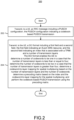
- FIG. 1 is a flowchart illustrating a method/process 100 performed by a UE for codebook-based PUSCH transmission, according to an example implementation of the present disclosure.
- the process 100 may start by receiving, from a BS, an RRC message including a PUSCH configuration.
- the PUSCH configuration may indicate a codebook-based PUSCH transmission.
- the PUSCH configuration may include a PUSCH-Config IE.
- the PUSCH-Config IE may include a field txConfig set to the codebook.
- the txConfig may be set to the codebook to indicate a CB PUSCH transmission or may be set to a noncodebook to indicate an NCB PUSCH transmission.
- the process 100 may receive, from the BS, a DCI format including a first field and a second field.
- the first field may indicate an 8-port SRS resource.
- the first field may include an SRS Resource Indicator (SRI).
- SRI SRS Resource Indicator
- the second field may indicate an index that is associated with a TPMI and a number of transmission layers.
- the DCI format may schedule the codebook-based PUSCH transmission.
- the process 100 may determine a number of codewords to be one in a case that the number of transmission layers is less than or equal to four.
- the process 100 may determine the number of codewords to be two in a case that the number of transmission layers is greater than four.
- the number of codewords used for the layer mapping may be one if the number of transmission layers indicated in the DCI format is one of ⁇ 1, 2, 3, 4 ⁇ , and the number of codewords used for the layer mapping may be two if the number of transmission layers indicated in the DCI format is one of ⁇ 5, 6, 7, 8 ⁇ .
- the process 100 may determine a codeword-to-layer mapping for spatial multiplexing based on the number of transmission layers and the number of codewords.
- the codeword-to-layer mapping may represent a procedure that maps complex-valued modulation symbols, for each codeword, to the transmission layers.
- a first codeword may be used for the codeword-to-layer mapping for the spatial multiplexing.
- Complex-valued modulation symbols belonging to the first codeword may be mapped to the transmission layers in sequence.
- An example layer mapping is shown in Table 2.
- a first codeword and a second codeword may be used for the codeword-to-layer mapping for spatial multiplexing.
- the number of transmission layers is five
- complex-valued modulation symbols belonging to the first codeword may be mapped to first two transmission layers in sequence and complex-valued modulation symbols belonging to the second codeword may be mapped to third to fifth transmission layers in sequence.
- the number of transmission layers is six
- complex-valued modulation symbols belonging to the first codeword may be mapped to first three transmission layers in sequence and complex-valued modulation symbols belonging to the second codeword may be mapped to fourth to sixth transmission layers in sequence.
- complex-valued modulation symbols belonging to the first codeword may be mapped to first three transmission layers in sequence and complex-valued modulation symbols belonging to the second codeword may be mapped to fourth to seventh transmission layers in sequence.
- complex-valued modulation symbols belonging to the first codeword may be mapped to first four transmission layers in sequence and complex-valued modulation symbols belonging to the second codeword may be mapped to fifth to eighth transmission layers in sequence.
- An example layer mapping is shown in Table 2.
- the process 100 may determine a precoding matrix based on the index and the codeword-to-layer mapping for the spatial multiplexing.
- the PUSCH configuration may further indicate a maximum transmission rank (e.g., the maxRank or maxRankDCI-0-2 ), a transform precoding configuration, and a codebook subset configuration (e.g., the codebookSubset or codebookSubsetDCI-0-2 ).
- Determining the precoding matrix in action 112 may include determining a dedicated table based on the maximum transmission rank, the transform precoding configuration, and the codebook subset configuration; and determining the precoding matrix based on the dedicated table and the index.
- the dedicated table may include two columns for each value of the maximum transmission rank. The first column of the dedicated table may correspond to the index, and the second column of the dedicated table may correspond to a combination of the number of transmission layers and the TPMI.
- the process 100 may perform the codebook-based PUSCH transmission using the precoding matrix. The process 100 may then end.
- the maximum transmission rank may be one of 1, 2, 4, and 8.
- the codebook subset configuration may indicate the number of antenna groups (e.g., N g ). Transmission antenna ports that belong to the same antenna group may be regarded as coherent.
- the number of antenna groups (e.g., N g ) may be one of 1, 2, 4, and 8.
- the index may correspond to multiple sub-indices.
- the sub-indices may be grouped into multiple pairs sequentially.
- the number of pairs may be equal to the number of antenna groups.
- i 7 which may be grouped sequentially in four pairs ⁇ i 0 , i 1 ⁇ , ⁇ i 2 , i 3 ⁇ , ⁇ i 4 , i 3 ⁇ , and ⁇ i 6 , i 7 ⁇ . Each pair may correspond to a sub-precoding matrix applied to one of the four antenna groups.
- the pairs may include a first pair and a second pair.
- Each of the first and second pairs may include a first sub-index and a second sub-index.
- the first sub-index (e.g., i 0 , i 2 , i 4 , i 6 ) may correspond to the number of transmission layers.
- the second sub-index (e.g., i 1 , i 3 , i 5 , i 7 ) may correspond to a sub-TPMI.
- the first sub-index of the first pair may be different from the first sub-index of the second pair.
- the first pair and the second pair may correspond to different numbers of transmission layers.
- FIG. 1 should not be construed as necessarily order dependent. The order in which the process is described is not intended to be construed as a limitation. Moreover, some of the actions in FIG. 1 may be omitted in some implementations.
- the technical problem addressed by the method illustrated in FIG. 1 is how to efficiently perform codebook-based PUSCH transmission, which includes determining the number of codewords based on the number of transmission layers. Because the codeword-to-layer mapping for spatial multiplexing is determined dynamically based on the number of transmission layers, the UE may determine an optimum precoding matrix for the codebook-based PUSCH transmission accordingly. This method may help to improve signal quality, increase data throughput, and reduce interference, leading to enhanced performance for the codebook-based PUSCH transmission.
- FIG. 2 is a flowchart illustrating a method/process 200 performed by a BS for configuring codebook-based PUSCH transmission, according to an example implementation of the present disclosure.
- the process 200 may be performed by the BS.
- the process 200 may start by transmitting, to a UE, an RRC message including a PUSCH configuration.
- the PUSCH configuration may indicate a codebook-based PUSCH transmission.
- the process may transmit, to the UE, a DCI format including a first field and a second field.
- the first field may indicate an 8-port SRS resource
- the second field may indicate an index that is associated with a TPMI and the number of transmission layers.
- the DCI format may enable the UE to: determine the number of codewords to be one in a case that the number of transmission layers is less than or equal to four; determine the number of codewords to be two in a case that the number of transmission layers is greater than four; determine a codeword-to-layer mapping for spatial multiplexing based on the number of transmission layers and the number of codewords; determine a precoding matrix based on the index and the codeword-to-layer mapping for the spatial multiplexing; and perform the codebook-based PUSCH transmission using the precoding matrix.
- the process 200 may then end.
- FIG. 2 The method illustrated in FIG. 2 is similar to that in FIG. 1 , except that it is described from the perspective of the BS (instead of the UE).
- FIG. 3 is a block diagram illustrating a node 300 for wireless communication in accordance with various aspects of the present disclosure.
- a node 300 may include a transceiver 320, a processor 328, a memory 334, one or more presentation components 338, and at least one antenna 336.
- the node 300 may also include a radio frequency (RF) spectrum band module, a BS communications module, a network communications module, and a system communications management module, Input / Output (I/O) ports, I/O components, and a power supply (not illustrated in FIG. 3 ).
- RF radio frequency
- the node 300 may be a UE or a BS that performs various functions disclosed with reference to FIGS. 1 through 2 .
- the transceiver 320 has a transmitter 322 (e.g., transmitting/transmission circuitry) and a receiver 324 (e.g., receiving/reception circuitry) and may be configured to transmit and/or receive time and/or frequency resource partitioning information.
- the transceiver 320 may be configured to transmit in different types of subframes and slots including, but not limited to, usable, non-usable, and flexibly usable subframes and slot formats.
- the transceiver 320 may be configured to receive data and control channels.
- the node 300 may include a variety of computer-readable media.
- Computer-readable media may be any available media that may be accessed by the node 300 and include volatile (and/or non-volatile) media and removable (and/or non-removable) media.
- the computer-readable media may include computer-storage media and communication media.
- Computer-storage media may include both volatile (and/or non-volatile media), and removable (and/or non-removable) media implemented in any method or technology for storage of information such as computer-readable instructions, data structures, program modules, or data.
- Computer-storage media may include RAM, ROM, EPROM, EEPROM, flash memory (or other memory technology), CD-ROM, Digital Versatile Disks (DVD) (or other optical disk storage), magnetic cassettes, magnetic tape, magnetic disk storage (or other magnetic storage devices), etc.
- Computer-storage media may not include a propagated data signal.
- Communication media may typically embody computer-readable instructions, data structures, program modules, or other data in a modulated data signal, such as a carrier wave, or other transport mechanisms and include any information delivery media.
- modulated data signal may mean a signal that has one or more of its characteristics set or changed in such a manner as to encode information in the signal.
- Communication media may include wired media, such as a wired network or direct-wired connection, and wireless media, such as acoustic, RF, infrared, and other wireless media. Combinations of any of the above listed components should also be included within the scope of computer-readable media.
- the memory 334 may include computer-storage media in the form of volatile and/or non-volatile memory.
- the memory 334 may be removable, non-removable, or a combination thereof.
- Example memory may include solid-state memory, hard drives, optical-disc drives, etc.
- the memory 334 may store a computer-readable and/or computer-executable instructions 332 (e.g., software codes) that are configured to, when executed, cause the processor 328 to perform various functions disclosed herein, for example, with reference to FIGS. 1 through 2 .
- the instructions 332 may not be directly executable by the processor 328 but may be configured to cause the node 300 (e.g., when compiled and executed) to perform various functions disclosed herein.
- the processor 328 may include an intelligent hardware device, e.g., a Central Processing Unit (CPU), a microcontroller, an ASIC, etc.
- the processor 328 may include memory.
- the processor 328 may process the data 330 and the instructions 332 received from the memory 334, and information transmitted and received via the transceiver 320, the baseband communications module, and/or the network communications module.
- the processor 328 may also process information to send to the transceiver 320 for transmission via the antenna 336 to the network communications module for transmission to a CN.
- One or more presentation components 338 may present data indications to a person or another device.
- Examples of presentation components 338 may include a display device, a speaker, a printing component, a vibrating component, etc.
Landscapes
- Engineering & Computer Science (AREA)
- Signal Processing (AREA)
- Computer Networks & Wireless Communication (AREA)
- Mobile Radio Communication Systems (AREA)
Applications Claiming Priority (1)
| Application Number | Priority Date | Filing Date | Title |
|---|---|---|---|
| US202363526542P | 2023-07-13 | 2023-07-13 |
Publications (2)
| Publication Number | Publication Date |
|---|---|
| EP4492701A2 true EP4492701A2 (de) | 2025-01-15 |
| EP4492701A3 EP4492701A3 (de) | 2025-03-12 |
Family
ID=91946809
Family Applications (1)
| Application Number | Title | Priority Date | Filing Date |
|---|---|---|---|
| EP24188322.2A Pending EP4492701A3 (de) | 2023-07-13 | 2024-07-12 | Verfahren und vorrichtung für codebuchbasierte übertragung eines gemeinsam genutzten physikalischen uplink-kanals (pusch) |
Country Status (3)
| Country | Link |
|---|---|
| US (1) | US12506522B2 (de) |
| EP (1) | EP4492701A3 (de) |
| CN (1) | CN119316109A (de) |
Family Cites Families (4)
| Publication number | Priority date | Publication date | Assignee | Title |
|---|---|---|---|---|
| EP3864913A4 (de) * | 2018-10-11 | 2022-06-08 | Lenovo (Beijing) Limited | Verfahren und vorrichtung für codebuch-basierte mehrplatten- und/oder mehrträger-psa-übertragungen |
| US11751186B2 (en) * | 2020-07-21 | 2023-09-05 | Qualcomm Incorporated | Single layer uplink non-codebook based precoding optimization |
| CN117981436A (zh) | 2021-07-21 | 2024-05-03 | 株式会社Ntt都科摩 | 终端、无线通信方法以及基站 |
| JP2024527664A (ja) | 2021-07-23 | 2024-07-26 | インテル コーポレイション | 強化されたマルチレイヤアップリンク伝送 |
-
2024
- 2024-07-12 EP EP24188322.2A patent/EP4492701A3/de active Pending
- 2024-07-12 US US18/771,848 patent/US12506522B2/en active Active
- 2024-07-12 CN CN202410938149.8A patent/CN119316109A/zh active Pending
Also Published As
| Publication number | Publication date |
|---|---|
| CN119316109A (zh) | 2025-01-14 |
| EP4492701A3 (de) | 2025-03-12 |
| US12506522B2 (en) | 2025-12-23 |
| US20250030465A1 (en) | 2025-01-23 |
Similar Documents
| Publication | Publication Date | Title |
|---|---|---|
| EP4128642B1 (de) | Verfahren und benutzergerät für operationen mit mehreren sende-/empfangspunkten | |
| US12484051B2 (en) | Wireless communication method and user equipment for non-CodeBook PUSCH transmission | |
| EP3954081B1 (de) | Verfahren zur ableitung einer qcl-annahme bei einer multipanelübertragung und zugehörige vorrichtung | |
| US10484070B2 (en) | Method and apparatus for channel state information reference signal (CSI-RS) | |
| WO2022206944A1 (en) | User equipment and method for uplink transmission | |
| US20210204277A1 (en) | User equipment and method for activating pucch spatial relation | |
| US8711907B2 (en) | PMI feedback with codebook interpolation | |
| WO2021204225A1 (en) | Method of performing non-codebook based physical uplink shared channel transmission and related device | |
| US12531677B2 (en) | User equipment and method for multi-TRP based PUSCH transmission | |
| EP4443805A1 (de) | Benutzergerät, basisstation und verfahren zur meldung von kanalstatusinformationen | |
| US12532269B2 (en) | User equipment and method for transmitting power headroom report | |
| US20250106784A1 (en) | Method and apparatus for full power transmission in wireless networks | |
| US20240340918A1 (en) | Methods and apparatuses for uplink transmission enhancement | |
| WO2025183029A1 (en) | Method and apparatus for handling on-demand synchronization signal block (od-ssb) transmission/reception | |
| US20240381349A1 (en) | USER EQUIPMENT, BASE STATION, AND METHOD FOR SIMULTANEOUS TRANSMISSION WITH MULTI-PANEL (STxMP) OPERATIONS | |
| EP4492701A2 (de) | Verfahren und vorrichtung für codebuchbasierte übertragung eines gemeinsam genutzten physikalischen uplink-kanals (pusch) | |
| WO2024160244A1 (en) | User equipment, base station, and method for codebook based pusch transmission | |
| WO2025036259A1 (en) | Methods and apparatuses for network energy saving | |
| WO2026034349A1 (en) | Apparatus and method for layer 1/layer 2 triggered mobility with event-triggered measurement reporting | |
| WO2025095145A1 (en) | Methods and apparatuses for full power transmissions | |
| WO2024141059A1 (en) | USER EQUIPMENT, BASE STATION, AND METHOD FOR STxMP OPERATION | |
| WO2020181635A1 (en) | Bases selection in two-part uplink control information reporting |
Legal Events
| Date | Code | Title | Description |
|---|---|---|---|
| PUAI | Public reference made under article 153(3) epc to a published international application that has entered the european phase |
Free format text: ORIGINAL CODE: 0009012 |
|
| STAA | Information on the status of an ep patent application or granted ep patent |
Free format text: STATUS: THE APPLICATION HAS BEEN PUBLISHED |
|
| AK | Designated contracting states |
Kind code of ref document: A2 Designated state(s): AL AT BE BG CH CY CZ DE DK EE ES FI FR GB GR HR HU IE IS IT LI LT LU LV MC ME MK MT NL NO PL PT RO RS SE SI SK SM TR |
|
| PUAL | Search report despatched |
Free format text: ORIGINAL CODE: 0009013 |
|
| AK | Designated contracting states |
Kind code of ref document: A3 Designated state(s): AL AT BE BG CH CY CZ DE DK EE ES FI FR GB GR HR HU IE IS IT LI LT LU LV MC ME MK MT NL NO PL PT RO RS SE SI SK SM TR |
|
| RIC1 | Information provided on ipc code assigned before grant |
Ipc: H04B 7/0456 20170101ALI20250204BHEP Ipc: H04B 7/0404 20170101AFI20250204BHEP |
|
| STAA | Information on the status of an ep patent application or granted ep patent |
Free format text: STATUS: REQUEST FOR EXAMINATION WAS MADE |
|
| 17P | Request for examination filed |
Effective date: 20250911 |