EP4128642B1 - Verfahren und benutzergerät für operationen mit mehreren sende-/empfangspunkten - Google Patents
Verfahren und benutzergerät für operationen mit mehreren sende-/empfangspunkten Download PDFInfo
- Publication number
- EP4128642B1 EP4128642B1 EP21805282.7A EP21805282A EP4128642B1 EP 4128642 B1 EP4128642 B1 EP 4128642B1 EP 21805282 A EP21805282 A EP 21805282A EP 4128642 B1 EP4128642 B1 EP 4128642B1
- Authority
- EP
- European Patent Office
- Prior art keywords
- pusch
- tpmi
- panel
- trp
- srs resource
- Prior art date
- Legal status (The legal status is an assumption and is not a legal conclusion. Google has not performed a legal analysis and makes no representation as to the accuracy of the status listed.)
- Active
Links
Images


Classifications
-
- H—ELECTRICITY
- H04—ELECTRIC COMMUNICATION TECHNIQUE
- H04W—WIRELESS COMMUNICATION NETWORKS
- H04W72/00—Local resource management
- H04W72/12—Wireless traffic scheduling
- H04W72/1263—Mapping of traffic onto schedule, e.g. scheduled allocation or multiplexing of flows
- H04W72/1268—Mapping of traffic onto schedule, e.g. scheduled allocation or multiplexing of flows of uplink data flows
-
- H—ELECTRICITY
- H04—ELECTRIC COMMUNICATION TECHNIQUE
- H04L—TRANSMISSION OF DIGITAL INFORMATION, e.g. TELEGRAPHIC COMMUNICATION
- H04L5/00—Arrangements affording multiple use of the transmission path
- H04L5/003—Arrangements for allocating sub-channels of the transmission path
- H04L5/0032—Distributed allocation, i.e. involving a plurality of allocating devices, each making partial allocation
- H04L5/0035—Resource allocation in a cooperative multipoint environment
-
- H—ELECTRICITY
- H04—ELECTRIC COMMUNICATION TECHNIQUE
- H04B—TRANSMISSION
- H04B7/00—Radio transmission systems, i.e. using radiation field
- H04B7/02—Diversity systems; Multi-antenna system, i.e. transmission or reception using multiple antennas
- H04B7/04—Diversity systems; Multi-antenna system, i.e. transmission or reception using multiple antennas using two or more spaced independent antennas
- H04B7/0404—Diversity systems; Multi-antenna system, i.e. transmission or reception using multiple antennas using two or more spaced independent antennas the mobile station comprising multiple antennas, e.g. to provide uplink diversity
-
- H—ELECTRICITY
- H04—ELECTRIC COMMUNICATION TECHNIQUE
- H04B—TRANSMISSION
- H04B7/00—Radio transmission systems, i.e. using radiation field
- H04B7/02—Diversity systems; Multi-antenna system, i.e. transmission or reception using multiple antennas
- H04B7/04—Diversity systems; Multi-antenna system, i.e. transmission or reception using multiple antennas using two or more spaced independent antennas
- H04B7/0413—MIMO systems
- H04B7/0456—Selection of precoding matrices or codebooks, e.g. using matrices antenna weighting
-
- H—ELECTRICITY
- H04—ELECTRIC COMMUNICATION TECHNIQUE
- H04B—TRANSMISSION
- H04B7/00—Radio transmission systems, i.e. using radiation field
- H04B7/02—Diversity systems; Multi-antenna system, i.e. transmission or reception using multiple antennas
- H04B7/04—Diversity systems; Multi-antenna system, i.e. transmission or reception using multiple antennas using two or more spaced independent antennas
- H04B7/06—Diversity systems; Multi-antenna system, i.e. transmission or reception using multiple antennas using two or more spaced independent antennas at the transmitting station
- H04B7/0613—Diversity systems; Multi-antenna system, i.e. transmission or reception using multiple antennas using two or more spaced independent antennas at the transmitting station using simultaneous transmission
- H04B7/0615—Diversity systems; Multi-antenna system, i.e. transmission or reception using multiple antennas using two or more spaced independent antennas at the transmitting station using simultaneous transmission of weighted versions of same signal
- H04B7/0619—Diversity systems; Multi-antenna system, i.e. transmission or reception using multiple antennas using two or more spaced independent antennas at the transmitting station using simultaneous transmission of weighted versions of same signal using feedback from receiving side
- H04B7/0621—Feedback content
- H04B7/0628—Diversity capabilities
-
- H—ELECTRICITY
- H04—ELECTRIC COMMUNICATION TECHNIQUE
- H04B—TRANSMISSION
- H04B7/00—Radio transmission systems, i.e. using radiation field
- H04B7/02—Diversity systems; Multi-antenna system, i.e. transmission or reception using multiple antennas
- H04B7/04—Diversity systems; Multi-antenna system, i.e. transmission or reception using multiple antennas using two or more spaced independent antennas
- H04B7/06—Diversity systems; Multi-antenna system, i.e. transmission or reception using multiple antennas using two or more spaced independent antennas at the transmitting station
- H04B7/0613—Diversity systems; Multi-antenna system, i.e. transmission or reception using multiple antennas using two or more spaced independent antennas at the transmitting station using simultaneous transmission
- H04B7/0615—Diversity systems; Multi-antenna system, i.e. transmission or reception using multiple antennas using two or more spaced independent antennas at the transmitting station using simultaneous transmission of weighted versions of same signal
- H04B7/0619—Diversity systems; Multi-antenna system, i.e. transmission or reception using multiple antennas using two or more spaced independent antennas at the transmitting station using simultaneous transmission of weighted versions of same signal using feedback from receiving side
- H04B7/0636—Feedback format
- H04B7/0639—Using selective indices, e.g. of a codebook, e.g. pre-distortion matrix index [PMI] or for beam selection
-
- H—ELECTRICITY
- H04—ELECTRIC COMMUNICATION TECHNIQUE
- H04L—TRANSMISSION OF DIGITAL INFORMATION, e.g. TELEGRAPHIC COMMUNICATION
- H04L1/00—Arrangements for detecting or preventing errors in the information received
- H04L1/08—Arrangements for detecting or preventing errors in the information received by repeating transmission, e.g. Verdan system
-
- H—ELECTRICITY
- H04—ELECTRIC COMMUNICATION TECHNIQUE
- H04L—TRANSMISSION OF DIGITAL INFORMATION, e.g. TELEGRAPHIC COMMUNICATION
- H04L5/00—Arrangements affording multiple use of the transmission path
- H04L5/003—Arrangements for allocating sub-channels of the transmission path
- H04L5/0037—Inter-user or inter-terminal allocation
-
- H—ELECTRICITY
- H04—ELECTRIC COMMUNICATION TECHNIQUE
- H04L—TRANSMISSION OF DIGITAL INFORMATION, e.g. TELEGRAPHIC COMMUNICATION
- H04L5/00—Arrangements affording multiple use of the transmission path
- H04L5/003—Arrangements for allocating sub-channels of the transmission path
- H04L5/0048—Allocation of pilot signals, i.e. of signals known to the receiver
-
- H—ELECTRICITY
- H04—ELECTRIC COMMUNICATION TECHNIQUE
- H04L—TRANSMISSION OF DIGITAL INFORMATION, e.g. TELEGRAPHIC COMMUNICATION
- H04L5/00—Arrangements affording multiple use of the transmission path
- H04L5/0091—Signalling for the administration of the divided path, e.g. signalling of configuration information
- H04L5/0094—Indication of how sub-channels of the path are allocated
-
- H—ELECTRICITY
- H04—ELECTRIC COMMUNICATION TECHNIQUE
- H04W—WIRELESS COMMUNICATION NETWORKS
- H04W72/00—Local resource management
- H04W72/20—Control channels or signalling for resource management
- H04W72/23—Control channels or signalling for resource management in the downlink direction of a wireless link, i.e. towards a terminal
-
- H—ELECTRICITY
- H04—ELECTRIC COMMUNICATION TECHNIQUE
- H04W—WIRELESS COMMUNICATION NETWORKS
- H04W8/00—Network data management
- H04W8/22—Processing or transfer of terminal data, e.g. status or physical capabilities
- H04W8/24—Transfer of terminal data
-
- H—ELECTRICITY
- H04—ELECTRIC COMMUNICATION TECHNIQUE
- H04L—TRANSMISSION OF DIGITAL INFORMATION, e.g. TELEGRAPHIC COMMUNICATION
- H04L1/00—Arrangements for detecting or preventing errors in the information received
- H04L1/12—Arrangements for detecting or preventing errors in the information received by using return channel
- H04L1/16—Arrangements for detecting or preventing errors in the information received by using return channel in which the return channel carries supervisory signals, e.g. repetition request signals
- H04L1/18—Automatic repetition systems, e.g. Van Duuren systems
- H04L1/1822—Automatic repetition systems, e.g. Van Duuren systems involving configuration of automatic repeat request [ARQ] with parallel processes
Definitions
- the present disclosure generally relates to wireless communication, and more particularly, to a method performed by a User Equipment (UE) and a corresponding UE.
- UE User Equipment
- next-generation wireless communication system such as the fifth-generation (5G) New Radio (NR)
- 5G fifth-generation
- NR New Radio
- CB-based UL transmission has been used in commercial communication systems such as W-CDMA, LTE, and NR.
- NW network
- the operation of a CB-based UL transmission may depend on network (NW) indications (e.g., transmit parameter(s) including Transmit Rank Indication (TRI), Transmit Precoder Matrix Indication (TPMI), Sounding Reference Signal (SRS) resource indication (SRI), Modulation Coding Scheme (MCS), and/or Transmit Power Control (TPC)).
- NW network
- NW network
- transmit parameter(s) including Transmit Rank Indication (TRI), Transmit Precoder Matrix Indication (TPMI), Sounding Reference Signal (SRS) resource indication (SRI), Modulation Coding Scheme (MCS), and/or Transmit Power Control (TPC)).
- TRI Transmit Rank Indication
- TPMI Transmit Precoder Matrix Indication
- SRS Sounding Reference Signal
- MCS Modulation Coding Scheme
- TPC Transmit Power Control
- a TRI and a TPMI may be common signaling content and associated with an SRS resource set that includes at least one SRS resource used for channel sounding at the NW side.
- a UE may be configured with multiple SRS resource sets. At least one of the configured SRS resource sets may be indicated by the NW via an SRI. The value of the NW indication described previously may be determined by the network based on channel conditions with respect to a UE.
- a TPMI may be referred to as a Precoder Matrix Indication (PMI).
- PMI Precoder Matrix Indication
- Figure 1 is a diagram illustrating a procedure for a CB-based UL transmission according to an implementation of the present disclosure.
- a UE 120 may report a UE capability message to a BS 140 (e.g., gNB).
- the BS 140 configures the UE with one or multiple SRS resource sets (e.g., via RRC signaling).
- the UE 120 is configured to transmit the configured SRS resource(s) to the BS 140 for UL channel estimation.
- the BS 140 may calculate a precoder and rank based on the SRS resource(s) received from the UE 120.
- the BS 140 may provide one or more transmit parameters (e.g., TRI, TMPI and/or SRI) to the UE 120 via scheduling DCI (or "UL DCI").
- the UE 120 is configured to perform PUSCH transmission(s) based on the transmit parameter(s) provided in the scheduling DCI.
- PUSCH enhancement in NR may be achieved by introducing repetition mechanisms in PUSCH transmissions to increase transmission reliability, with different PUSCH repetitions targeting different TRPs. If the repetition mechanisms are applied, the NW may include some transmit parameters (e.g., TPMI, MCS, and/or TPC) in the scheduling DCI to inform the UE how to perform the PUSCH repetitions.
- a "PUSCH repetition" may refer to one of one or more repeated PUSCH transmissions performed by a UE.
- a TPMI and a UL beam associated with the TMPI may be applied to a PUSCH transmission.
- different TRPs may be located at different geographic positions. Therefore, the transmit parameters for PUSCH transmissions toward different TRPs may be different due to different channel conditions. Details on how to inform a UE of multiple sets of transmit parameters for repetitive TRPs/PUSCH transmissions may require clarification.
- a UE with beamforming capability is usually equipped with multiple antenna panels. With each antenna panel providing spatial coverage potential in a different direction, multiple antenna panels contribute to an aggregated spatial coverage in an isotropic/omni-directional manner. As a result, selecting applicable antenna panels for PUSCH repetitions is another issue for PUSCH enhancement in multi-TRP scenarios.
- an antenna panel or simply referred to as "panel"
- one or more antenna elements may be placed in a particular way to form an antenna array.
- Each antenna panel may be used as a basic unit for beamforming. Therefore, beam indication may need to be jointly considered with panel selection/indication.
- a UE may report its capability (e.g., support of full-coherence, partial-coherence, or non-coherence among individual antenna ports) to the BS.
- its capability e.g., support of full-coherence, partial-coherence, or non-coherence among individual antenna ports
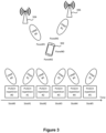
- FIG. 2 is a schematic diagram illustrating a multi-TRP operation based on CB-based PUSCH repetitions according to an implementation of the present disclosure.
- a UE 202 is in a multi-TRP scenario where two TRPs 204 and 206 are communicating with the UE 202.
- the UE 202 may be equipped with certain capabilities (e.g., fast panel switching) to carry out the NW instruction(s) carried in the DCI signaling if the UE 202 supports using the different TPMIs for different PUSCH repetitions.
- the UE 202 may use panel#0/SRI#0 and TPMI#0 to perform PUSCH repetitions#0, #2 and #4, and use panel#1/SRI#1 and TPMI#1 to perform PUSCH repetitions#1, #3 and #5.
- panel switching may be performed in each time slot (e.g., slot#0, #1, #2, #3, #4 or #5).
- a UE may select an applicable panel (e.g., the panel providing the largest channel gain) to transmit PUSCH (repetitions) to different TRPs.
- different SRS resources may be transmitted via different UL beams associated with different panels.
- the size of an SRS resource set may be extended (which is referred to "SRS resource extension" in the present disclosure).
- SRS resource extension the maximum number of SRS resources in an SRS resource set may be more than two. If SRS resources extension is applied, the information needed for UL transmission (e.g., PUSCH transmission) may be provided in a UL Transmission Configuration Indication (TCI) field and/or an SRI in DCI.
- TCI Transmission Configuration Indication
- such information may include power related information, beam related information (e.g., beam indications), precoders (e.g., TPMIs), SRS resource index(es) used the derivation of the essential information, and/or panel indications.
- beam related information e.g., beam indications
- precoders e.g., TPMIs
- SRS resource index(es) used the derivation of the essential information
- a single piece of DCI may include multiple TPMIs and multiple SRIs/panel indications, where each TPMI may identify a precoder to be applied to a UL transmission, and each SRI (or panel indication) may identify a panel to perform the UL transmission.
- the (single piece of) DCI may have a UL DCI format that includes at least two TPMI fields and at least two SRI fields (or panel indication fields), where each TPMI field may contain a TPMI, and each SRI field (or panel indication field) may contain an SRI (or panel indication).
- an SRI field may be used to implicitly indicate a panel that is suitable to be used for PUSCH transmission.
- the bit length of a TPMI and/or an SRI may be increased, depending on the number of TRPs, and/or the number of panels on the UE.
- the bit length of a TPMI and/or an SRI may depend on the number of active panels on the UE.
- a table that describes the correspondence relationship between the value(s) indicated by the TPMI/SRI/panel indication field(s) and the corresponding precoder(s)/beam(s)/panel(s) may be provided.
- a UE is configured to obtain, from RRC signaling, information on whether the TPMI and SRI (or panel indication) associated with each PUSCH repetition remains the same.
- the UE may expect that the DCI format it monitors for a PUSCH transmission in multi-TRP operations carries only one TPMI and/or only one SRI (or panel indication), e.g., only one TPMI, SRI (or panel indication) field, only one UL TCI in the DCI format associating with or providing information on TPMI, SRI (or panel indication), and so on, but not limited to.
- the network may inform a UE of the number of pieces of DCI the UE should receive for PUSCH repetitions (i.e., the number of DCI messages the UE should receive for PUSCH repetitions) in multi-TRP operations.
- the PUSCH repetitions triggered by the same UL DCI may be mapped to different beams, panels, or Redundancy Version (RV)s.
- RV Redundancy Version
- the rule of mapping the RVs, beams, and/or panels to the PUSCH repetitions may be predetermined.
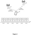
- Figure 3 is a schematic diagram illustrating multiple PUSCH repetitions mapped to different TPMIs according to an implementation of the present disclosure. As illustrated in Figure 3 , the mapping relationship between the PUSCH repetitions (e.g., PUSCH repetitions #0, #1, #2, #3, #4 and #5) and TPMIs is based on a round robin rule.
- PUSCH repetitions #0, #1, #2, #3, #4 and #5 e.g., PUSCH repetitions #0, #1, #2, #3, #4 and #5
- the UE 302 is configured with two TPMIs (e.g., TPMI#0 and TMPI#1) each indicating a (transmit) precoder for a PUSCH transmission to a TRP (e.g., TRP 304 or TRP 306), two RVs (e.g., RV#0 and RV#2), two panel indications (e.g., panel#1 and panel#3) each indicating a (antenna) panel equipped on the UE 302, and six PUSCH repetitions (i.e., the number of repetitions for one PUSCH scheduling is six), according to the round robin rule, TPMI#0, RV#0, and panel#1 map to PUSCH repetition#0, PUSCH repetition#2 and PUSCH repetition#4, while TPMI#1, RV#2, and panel#3 are mapped to PUSCH repetition#1, PUSCH repetition#3, and PUSCH repetition#5.
- TPMIs e.g., TPMI#0 and TMPI#1
- the UE may need to support panel switching in order to handle the instruction from the gNB.
- the gNB may request the UE to perform PUSCH repetition(s) in a set of (time) slots with UL resources, where the PUSCH repetition transmitted in each time slot may be transmitted via different panels of the UE.
- the panels of the UE may correspond to different TRPs.
- the set of slots may include multiple time slots that are continuous in the time domain. As illustrated in Figure 2 , 3 or 4 , slots#0 to #5 are arranged one after another in the time domain and therefore considered continuous in the time domain. In another example, the set of slots may include one or more slots that are not continuous in the time domain.
- the UE may inform the gNB whether it is equipped with such UE capability. For example, the UE may inform the gNB that it supports performing PUSCH repetitions in a multi-TRP scenario. In another example, the UE may inform the gNB that it supports performing PUSCH repetitions in a multi-TRP scenario by fast panel/beam switching.
- a new Information Element (IE) field(s) may be added to specific signaling to inform the network whether a UE supports fast panel switching in a multi-TRP scenario. If fast panel switching is supported, such signaling may be supported for non-fallback DCI format, such as format 0_1 and/or 0_2.
- IE Information Element
- the new IE field may be added in a parameter (e.g., MIMO-ParametersPerBand ) to indicate whether the UE supports performing PUSCH repetitions in a multi-TRP scenario by fast panel switching.
- a parameter e.g., MIMO-ParametersPerBand
- an IE may be provided to indicate whether the UE supports applying multiple transmit precoders (e.g., whether the UE supports decoding/parsing a DCI format(s) having one or multiple TPMI fields each including at least one TPMI value).
- the IE may be a parameter, pusch-multiTPMI, having an enumerated data type (defined by Abstract Syntax Notation One (ASN.1)) that is used to represent one of a list of enumerated values.
- ASN.1 Abstract Syntax Notation One
- an IE may be used to indicate whether the UE supports decoding/parsing multiple SRS resource information indications that are included in multiple DCI fields (e.g., SRI field(s)) of a DCI format.
- SRI field is simply an example of signaling.
- the IE may provide information on selected UL beam for associated PUSCH transmission by providing a reference RS.
- the IE may be included in a new field "UL-TCI".
- the field may co-exist or replace SRI field.
- An example of the IE may be represented as follows:
- an IE may be provided to indicate supporting multiple active UE panels for fast panel switching. Additionally or alternatively, the number of UE panels and/or the number of UE panels which can be simultaneously activated may be reported by the UE.
- the IE may be represented as follows:
- an IE may be provided to indicate supporting multiple active UE panels for fast panel switching. Additionally or alternatively, the number of UE panels and/or the number of UE panels which can be simultaneously activated may be reported by the UE.
- the IE may be represented as follows:
- the UE may implicitly indicate that the UE support fast panel switching, and the gNB may transmit the DCI carrying multiple TPMIs and SRIs (or panel indications).
- the gNB may signal the DCI carrying multiple TPMIs.
- the UE may implicitly inform the gNB that it may support PUSCH repetitions in multi-TRP operations.
- the UE may report how many panels/beams it can used to transmit PUSCH. After UE reports the number of its available panels/beams, the UE may obtain more than one SRS-CB resource sets (e.g., the usage of SRS set is set to 'codebook'), and/or the number of SRS-CB resources (e.g., the SRS resources used for CB-based UL transmission) may be greater than two.
- SRS-CB resource sets e.g., the usage of SRS set is set to 'codebook'
- the number of SRS-CB resources e.g., the SRS resources used for CB-based UL transmission
- the UE may transmit each SRS-CB resource set in the different time (e.g., time slot, subframe, and so on, but not limited to), e.g., the UE may not simultaneously transmit multiple SRS-CB resource sets in multi-TRP transmissions.
- the UE if the network indicates that type1 configured grant is used for PUSCH transmission in multi-TRP operations, the UE is configured to acquire the essential information (e.g., multiple TPMIs, multiple SRIs, multiple panel indications, and/or multiple TPC command for PUSCH transmission) used for PUSCH transmission in the dedicated RRC message.
- the essential information e.g., multiple TPMIs, multiple SRIs, multiple panel indications, and/or multiple TPC command for PUSCH transmission
- SRS resources extension may be needed to increase panel diversity.
- SRS resources extension may refer to increasing the maximum number of SRS resources configured in an SRS-CB resource set (e.g., an SRS resource set used for CB-based UL transmission) to be greater than two.
- FIG. 5 is a schematic diagram illustrating SRS resource extension that the number of SRS resources in an SRS resource set is up to four, in accordance with an implementation of the present disclosure.
- an SRS resource set 502 may be configured with up to four SRS resources (e.g., SRS resource#0 510, SRS resource #1 520, SRS resource #2 530 and SRS resource #3 540). Each SRS resource may be mapped to a specific panel/beam.
- SRS resource#0 510 may map to panel#0 and SRI#0;
- SRS resource#1 520 may map to panel#1 and SRI#1;
- SRS resource#2 530 may map to panel#2 and SRI#2;
- SRS resource#3 540 may map to panel#3 and SRI#3.
- a UE may transmit the SRS resources (e.g., SRS resource#0 510, SRS resource #1 520, SRS resource #2 530 and SRS resource #3 540, if there are four SRS resources configured in the SRS resource set 502) in the SRS resource set 502 in the UL direction.
- the gNB may perform channel estimation to derive proper transmit parameter(s), e.g., precoder(s), for a subsequent PUSCH transmission.
- the network may configure two SRS-CB resource sets to a UE to perform CB-based UL transmission in multi-TRP operations. These two SRS-CB resource sets may be transmitted at different time points (e.g., different OFDM symbols, time slots, or subframes) configured by the network. Based on the result of UE capability reporting (e.g., full coherence, partial coherence, or non-coherence) and the SRS resources included in the two SRS-CB resource sets, the gNB may determine two precoders for supporting PUSCH repetition in multi-TRP operations.
- UE capability reporting e.g., full coherence, partial coherence, or non-coherence
- PUSCH repetition#0 e.g., including PUSCH repetition#0, PUSCH repetition#2, PUSCH repetition#4, and PUSCH repetition#6
- the UE may use the TPMI to transmit another group of PUSCH repetitions (e.g., including PUSCH repetition#1, PUSCH repetition#3, PUSCH repetition#5, and PUSCH repetition#7).
- an SRS-CB resource set (e.g., an SRS resource set whose usage is set to 'codebook') may contain more than two SRS resources (i.e., SRS-CB resources).
- the number of SRS-CB resources may be explicitly indicated in an UL TCI.
- the UE may obtain the information of SRS-CB resources (e.g., the number of SRS-CB resource, and/or the position of SRS resources) contained in the UL TCI carried in the DCI format.
- the number of SRS-CB resources may be implicitly indicated. For example, the UE may report how many panels/beams it can use for PUSCH transmission. The number of SRS-CB resources may be associated with the number of panels/TX beams. The UE may then obtain the information of SRS resources in the SRS-CB resource set according to its panel/TX beam. For example, if the UE report that it is able use four panels to transmit PUSCH, the UE may expect that the number of SRS resources in a SRS-CB resource set is equal or less than four.
- the gNB may indicate the same panel/TX beam/TPMI to the UE for transmitting individual PUSCH repetitions.
- instructing a UE to apply different SRS resources in the SRS resource set may imply that panel switching between associated PUSCH transmissions is required.
- Panel switching may be subject to switch latency. In other words, there may be time gap at least between PUSCH transmissions with different panels.
- the number of SRS resource sets configured for channel sounding for CB-based UL transmission may be more than one.
- multiple SRS resource sets may be associated with different panels.
- multiple SRS resources belonging to different SRS resource sets are indicated by the SRI fields of a DCI format, it may imply that panel switch between associated PUSCH transmissions is required.
- one or more SRS resources belonging to the same SRS resource set is/are indicated by the SRI field(s) of a DCI format, it may imply that panel switch between associated PUSCH transmissions is not required.
- the UE may expect that the DCI format(s) that it monitors for PUSCH transmission may fulfill at least one of the following conditions (1) to (3):
- the UE is configured to to obtain multiple TPMIs, SRIs (or panel indications) via at least one of the following signaling:
- a UE may perform PUSCH repetitions (e.g., PUSCH repetitions#0 to #5) in a multi-TRP scenario to enhance transmission reliability. Since different TRPs (e.g., TRPs 204 and 206) may be located on different geographical areas, each TRP may correspond to a TPMI and an SRI (or panel indication) for an associated PUSCH repetition. In such a case, performing PUSCH repetitions in a multi-TRP scenario support multiple TPMIs/SRIs/panel indications.
- the DCI formats may carry UL TCI field providing essential information (e.g., SRIs, panel indications, the number of PUSCH repetitions, the start position of the OFDM symbol for each PUSCH repetition in different slots) for UL transmission.
- the multiple SRIs (or panel indications) may be included in the TCI of a DCI formats.
- a TCI in a DCI format may include two SRIs/panel indications.
- the first SRI (or panel indication) may indicate a beam/panel to be used to transmit the PUSCH repetition(s) to a TRP
- the second SRI (or panel indication) may indicate a beam/panel to be used to transmit the PUSCH repetition(s) to another TRP.
- the UE may obtain the number of PUSCH repetition via RRC signaling.
- the UE may obtain the resource allocation of the PUSCH transmission (i.e., the start symbol and the number of consecutive symbols for PUSCH transmission in a slot) by DCI format. And then all time slots used for PUSCH repetition may follow the same resource allocation.
- the UE may obtain multiple TPMIs, SRIs (or panel indications) in a DCI format.
- the mapping among RV, TPMI, SRI (or panel indication) and PUSCH repetition may be round robin as illustrated in Figure 3 .
- the PUSCH transmission in that slot may be canceled, and the mapping among RV, TPMI, SRI (or panel indication) and PUSCH repetition may not be changed, as illustrated in Figure 6 .
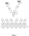
- Figure 6 is a schematic diagram illustrating that multiple PUSCH repetitions are canceled due to conflict with DL slots, in accordance with an implementation of the present disclosure.
- the UE 602 may need to apply TPMI#0 to transmit PUSCH repetitions #0, #2 and #4 to TRP 604 and apply TPMI#1 to transmit PUSCH repetitions# 1, #3 and #5 to TRP 606, but since PUSCH repetition#3 and PUSCH repetition#4 are allocated in slots#3 and #4 which are DL slots, the UE 602 may cancel PUSCH repetition#3 and PUSCH repetition#4 which are allocated in the DL slots.
- a new TPMI, SRI (or panel indications) table may be used for PUSCH transmission in multi-TRP operations.
- An example of the table is shown in Table 1.
- two TPMIs may be provided in each entry for a PUSCH transmission.
- the gNB may indicate to the UE an index #3.
- the term "layer” represents that the transmission channel(s) between a UE and a BS (e.g., a gNB).
- a layer can be viewed as the rank(s) of a MIMO channel matrix between a UE and a BS (e.g., a gNB).
- the table described previously may be associated with following factors (1) and (2):
- the table may indicate to the UE to use the same/different TPMIs and SRIs (or panel indications) for PUSCH transmission.
- the network may inform the UE whether the TPMI and SRI (or panel indication) used for PUSCH repetition in multi-TPR are the same or not via higher layer singling.
- the TPMI and SRI (or panel indication) used for PUSCH repetition in multi-TRP operations are the same via higher layer signaling
- the TPMI and SRI (or panel indication) carried in a single DCI message may be applied for each PUSCH repetition transmitted to different TRPs.
- the network may directly inform the UE, via higher layer signaling, that the TPMI and SRI (or panel indication) used for PUSCH repetition in multi-TRP operations are different.
- the UE may monitor two DCI messages in the different time slots for PUSCH transmission in multi-TRP operations.
- the UE may obtain multiple indications (e.g., TPMIs, SRIs (or panel indications), TPCs, and/or resource allocation parameters) used for individual PUSCH repetition.
- the network may indicate how many DCI messages the UE needs to decode for obtaining the TPMI(s) and SRI(s) (or panel indication(s)) for PUSCH repetitions.
- the network may indicate multiple search spaces for the UE to monitor multiple DCI messages. For example, if there are four DCI messages carrying information for UL transmission (e.g., TPMI, SRI, and/or panel indication), the network may configure four search spaces to the UE for PDCCH monitoring. The UE may monitor the DCI format scrambled with Cell-Radio Network Temporary Identifier (C-RNTI) in each configured search spaces for UL transmission.
- C-RNTI Cell-Radio Network Temporary Identifier
- the network may indicate multiple RNTIs for a UE to monitor multiple DCI messages in a search space, e.g., a dedicated search space used for multi-TRP transmission. For example, if there are four DCI messages carrying the information for UL transmission (e.g., TPMI, SRI, and/or panel indication), the network may configure four RNTIs and one search space to the UE for PDCCH monitoring. Then the UE may monitor DCI format scrambled with different Radio Network Temporary Identifiers (RNTIs) in a configured search spaces for UL transmission.
- RNTIs Radio Network Temporary Identifiers
- an RNTI used for multiple DCI monitoring may be related to at least one of (1) the number of TRPs used for UL transmission, and (2) the number of PUSCH repetitions.
- multiple DCI messages may be received for indicating PUSCH repetition of a UL scheduling.
Landscapes
- Engineering & Computer Science (AREA)
- Signal Processing (AREA)
- Computer Networks & Wireless Communication (AREA)
- Physics & Mathematics (AREA)
- Mathematical Physics (AREA)
- Databases & Information Systems (AREA)
- Mobile Radio Communication Systems (AREA)
Claims (2)
- Verfahren, das von einem Benutzergerät, UE (800), zum Kommunizieren mit einer Vielzahl von Übertragungs-Empfangspunkten (Engl. Transmission Reception Points), TRPs, durchgeführt wird, die einen ersten TRP und einen zweiten TRP beinhalten, wobei das Verfahren Folgendes umfasst;Empfangen, von einer Basisstation, BS, einer oder mehrerer Radio-Resource-Control-, RRC-Nachrichten, die das UE (800) mit einem ersten Sounding-Reference-Signal-, SRS-, Ressourcensatz, der dem ersten TRP zugeordnet ist, einem zweiten SRS-Ressourcensatz, der dem zweiten TRP zugeordnet ist, und einer Round-Robin-basierten Abbildungsvorschrift für eine Vielzahl von Physical-Uplink-Shared Channel-, PUSCH-Wiederholungen konfigurieren, wobei der erste SRS-Ressourcensatz und der zweite SRS-Ressourcensatz für Codebuch-basierte Übertragungen konfiguriert sind; undÜbertragen der Vielzahl von PUSCH-Wiederholungen anhand der Round-Robin-basierten Abbildungsvorschrift mindestens durch:Übertragen eines ersten Satzes von PUSCH-Wiederholungen aus der Vielzahl von PUSCH-Wiederholungen an den ersten TRP gemäß dem ersten SRS-Ressourcensatz und der Round-Robin-basierten Abbildungsvorschrift; undÜbertragen eines zweiten Satzes von PUSCH-Wiederholungen aus der Vielzahl von PUSCH-Wiederholungen an den zweiten TRP gemäß dem zweiten SRS-Ressourcensatz und der Round-Robin-basierten Abbildungsvorschrift,wobei:der erste Satz von PUSCH-Wiederholungen ungerade PUSCH-Wiederholungen der Vielzahl von PUSCH-Wiederholungen sind und der zweite Satz von PUSCH-Wiederholungen gerade PUSCH-Wiederholungen der Vielzahl von PUSCH-Wiederholungen sind,die eine oder mehrere RRC-Nachrichten eine erste Transmit-Precoder-Matrix-Indikation, TPMI, umfassen, die dem ersten SRS-Ressourcensatz zugeordnet ist, und eine zweite TPMI umfassen, die dem zweiten SRS-Ressourcensatz zugeordnet ist,die erste PUSCH-Wiederholung auf die erste TPMI abgebildet wird und die zweite PUSCH-Wiederholung auf die zweite TPMI abgebildet wird, gemäß der Round-Robin-basierten Abbildungsvorschrift, unddie eine oder mehrere RRC-Nachrichten ferner einen ersten SRS-Ressourcenindikator, SRI, umfassen, der dem ersten SRS-Ressourcensatz entspricht, und einen zweiten SRI umfassen, der dem zweiten SRS-Ressourcensatz entspricht.
- Benutzergerät, UE (800), zum Kommunizieren mit einer Vielzahl von Übertragungs-Empfangspunkten (Engl. transmission reception points), TRPs, durchgeführt wird, die einen ersten TRP und einen zweiten TRP beinhalten, wobei das UE (800) Folgendes umfasst:Transceiver-Schaltung (820); undmindestens einen Prozessor (828), der mit der Transceiver-Schaltung (820) gekoppelt und so konfiguriert ist, dass er die Transceiver-Schaltung (820) steuert, um das Verfahren nach Anspruch 1 durchzuführen.
Applications Claiming Priority (2)
| Application Number | Priority Date | Filing Date | Title |
|---|---|---|---|
| US202063023205P | 2020-05-11 | 2020-05-11 | |
| PCT/CN2021/092178 WO2021227958A1 (en) | 2020-05-11 | 2021-05-07 | Method and user equipment for multi-transmission/reception point operations |
Publications (3)
| Publication Number | Publication Date |
|---|---|
| EP4128642A1 EP4128642A1 (de) | 2023-02-08 |
| EP4128642A4 EP4128642A4 (de) | 2024-04-03 |
| EP4128642B1 true EP4128642B1 (de) | 2025-07-02 |
Family
ID=78526443
Family Applications (1)
| Application Number | Title | Priority Date | Filing Date |
|---|---|---|---|
| EP21805282.7A Active EP4128642B1 (de) | 2020-05-11 | 2021-05-07 | Verfahren und benutzergerät für operationen mit mehreren sende-/empfangspunkten |
Country Status (6)
| Country | Link |
|---|---|
| US (1) | US12588020B2 (de) |
| EP (1) | EP4128642B1 (de) |
| JP (2) | JP2023524309A (de) |
| KR (1) | KR20230005963A (de) |
| CN (1) | CN115443632A (de) |
| WO (1) | WO2021227958A1 (de) |
Families Citing this family (18)
| Publication number | Priority date | Publication date | Assignee | Title |
|---|---|---|---|---|
| US20230353298A1 (en) * | 2020-06-28 | 2023-11-02 | Lenovo (Beijing) Ltd. | Method and apparatus for mapping pusch repetitions |
| JP7578695B2 (ja) * | 2020-07-31 | 2024-11-06 | 株式会社Nttドコモ | 端末、無線通信方法、基地局及びシステム |
| CN116325854B (zh) * | 2020-08-06 | 2024-07-16 | 株式会社Ntt都科摩 | 终端、无线通信方法及基站 |
| US12349150B2 (en) * | 2021-01-17 | 2025-07-01 | Qualcomm Incorporated | Multiple sounding reference signal transmissions triggered by downlink control information |
| WO2022168812A1 (ja) * | 2021-02-04 | 2022-08-11 | 株式会社Nttドコモ | 端末、無線通信方法及び基地局 |
| WO2022213291A1 (en) * | 2021-04-06 | 2022-10-13 | Apple Inc. | Trp-specific pusch transmissions for multi-trp operation |
| US11737112B2 (en) | 2021-12-01 | 2023-08-22 | Qualcomm Incorporated | Sounding reference signal (SRS) resource sets for multiple downlink control information based systems |
| KR20240112276A (ko) * | 2021-12-01 | 2024-07-18 | 퀄컴 인코포레이티드 | 업링크 공간 분할 다중화를 위한 사운딩 기준 신호 리소스 표시자 및 송신 프리코더 매트릭스 표시자 시그널링 |
| CN116471688B (zh) * | 2022-01-11 | 2025-12-23 | 大唐移动通信设备有限公司 | 一种时域资源确定方法、终端设备及存储介质 |
| US20230300832A1 (en) * | 2022-03-17 | 2023-09-21 | Apple Inc. | Enhanced single-dci multi-panel uplink transmissions |
| US20250047456A1 (en) * | 2022-04-18 | 2025-02-06 | Qualcomm Incorporated | Mapping transmit-receive point identifiers to simultaneous uplink transmission components for multiple transmit-receive points |
| KR20250026774A (ko) * | 2022-06-29 | 2025-02-25 | 퀄컴 인코포레이티드 | 동시 업링크 송신을 위한 최대 수의 지원된 계층에 대한 사용자 장비 능력 |
| JP7798232B2 (ja) * | 2022-08-05 | 2026-01-14 | 1Finity株式会社 | 上りリンクデータ送信、上りリンクデータ受信装置及び方法 |
| KR20250023927A (ko) * | 2023-08-10 | 2025-02-18 | 현대자동차주식회사 | 통신 시스템에서 상향링크 송신 방법 및 장치 |
| CN120239052A (zh) * | 2023-12-29 | 2025-07-01 | 华为技术有限公司 | 一种通信方法及装置 |
| WO2025234006A1 (ja) * | 2024-05-08 | 2025-11-13 | 株式会社Nttドコモ | 端末、無線通信方法及び基地局 |
| WO2025231893A1 (en) * | 2024-05-10 | 2025-11-13 | Nokia Shanghai Bell Co., Ltd. | Method for uplink repetitions with multiple transmission-reception points in sub-band non-overlapping full duplex |
| US20260039339A1 (en) * | 2024-07-31 | 2026-02-05 | Qualcomm Incorporated | Techniques for control signaling for closed-loop antenna selection |
Family Cites Families (28)
| Publication number | Priority date | Publication date | Assignee | Title |
|---|---|---|---|---|
| KR102021590B1 (ko) * | 2012-06-04 | 2019-09-18 | 삼성전자주식회사 | 무선 통신 시스템에서 제어 정보 송수신 방법 및 장치 |
| US10716105B2 (en) * | 2017-02-14 | 2020-07-14 | Lg Electronics Inc. | Method for transmitting and receiving a physical downlink shared channel and a demodulation reference signal and apparatus therefor |
| RU2720462C1 (ru) * | 2017-03-31 | 2020-04-30 | ЭлДжи ЭЛЕКТРОНИКС ИНК. | Способ и устройство для передачи данных восходящей линии связи в системе беспроводной связи |
| WO2018199240A1 (ja) * | 2017-04-26 | 2018-11-01 | シャープ株式会社 | 端末装置、基地局装置、および、通信方法 |
| JP7085347B2 (ja) | 2017-12-27 | 2022-06-16 | シャープ株式会社 | 基地局装置、端末装置および通信方法 |
| US10863494B2 (en) * | 2018-01-22 | 2020-12-08 | Apple Inc. | Control signaling for uplink multiple input multiple output, channel state information reference signal configuration and sounding reference signal configuration |
| CN110831196B (zh) | 2018-08-14 | 2022-01-04 | 维沃移动通信有限公司 | Csi报告配置方法、终端设备和网络设备 |
| US20210184819A1 (en) * | 2018-08-27 | 2021-06-17 | Ntt Docomo, Inc. | User terminal and radio communication method |
| US11050525B2 (en) | 2018-09-27 | 2021-06-29 | Huawei Technologies Co., Ltd. | System and method for control and data channel reliability enhancement using multiple diversity domains |
| CN110535589B (zh) * | 2018-09-27 | 2023-01-10 | 中兴通讯股份有限公司 | 指示方法、信息确定方法、装置、基站、终端及存储介质 |
| US11522594B2 (en) * | 2018-10-11 | 2022-12-06 | Lenovo (Beijing) Limited | Method and apparatus for multiple panel and/or multiple beam codebook based PUSCH transmissions |
| US12010528B2 (en) * | 2018-11-01 | 2024-06-11 | Lg Electronics Inc. | Method for transmitting PUSCH in wireless communication system, and device therefor |
| CN118233059A (zh) * | 2019-01-04 | 2024-06-21 | 苹果公司 | 具有多传输接收点(trp)的物理下行链路控制信道 |
| US11317396B2 (en) * | 2019-05-14 | 2022-04-26 | Qualcomm Incorporated | PDSCH/PUSCH repetition enhancements for URLLC |
| US11496964B2 (en) * | 2019-08-02 | 2022-11-08 | Qualcomm Incorporated | Power boosting design for multi-slot shared channels |
| US11581978B2 (en) * | 2019-08-06 | 2023-02-14 | Qualcomm Incorporated | Uplink repetition configuration |
| CN110535614B (zh) | 2019-09-03 | 2024-08-09 | 中兴通讯股份有限公司 | 信令信息的传输方法、装置、通信节点和存储介质 |
| CN110536450B (zh) * | 2019-09-03 | 2025-02-11 | 中兴通讯股份有限公司 | 一种数据传输方法、装置、传输接收节点、终端及介质 |
| KR102688462B1 (ko) | 2019-09-18 | 2024-07-26 | 삼성전자주식회사 | 네트워크 협력 통신을 위한 상향링크 반복 전송 방법 및 장치 |
| US11234199B2 (en) * | 2020-01-15 | 2022-01-25 | Ofinno, Llc | Power control procedure in a wireless network |
| US11588523B2 (en) * | 2020-01-17 | 2023-02-21 | Qualcomm Incorporated | TPMI and/or SRI indication for codebook-based PUSCH repetition |
| EP4593302A3 (de) * | 2020-02-13 | 2025-08-06 | Telefonaktiebolaget LM Ericsson (publ) | Pusch-zuverlässigkeitsverbesserungen mit mehreren trp |
| EP3879738A1 (de) * | 2020-03-11 | 2021-09-15 | Fraunhofer Gesellschaft zur Förderung der angewandten Forschung e.V. | Verfahren und vorrichtungen für gemeinsam genutzten physikalischen uplink-kanal für kommunikation mit mehreren sende-empfangspunkten einem drahtloskommunikationsnetzwerk |
| WO2021181667A1 (ja) * | 2020-03-13 | 2021-09-16 | 株式会社Nttドコモ | 端末、無線通信方法及び基地局 |
| US11716761B2 (en) * | 2020-03-26 | 2023-08-01 | Electronics And Telecommunications Research Institute | Uplink transmission method for ultra-reliability and low-latency communication, and apparatus therefor |
| WO2021198982A1 (en) * | 2020-04-01 | 2021-10-07 | Telefonaktiebolaget Lm Ericsson (Publ) | PUSCH RESOURCE ALLOCATION WITH MULTIPLE TRPs |
| WO2021209979A1 (en) * | 2020-04-17 | 2021-10-21 | Telefonaktiebolaget Lm Ericsson (Publ) | Method and device for simultaneous transmission to multiple transmission and reception points (trps) |
| EP4113854B1 (de) * | 2020-04-29 | 2025-10-15 | LG Electronics, Inc. | Verfahren zum senden und empfangen einer aufwärtsstrecke für mehrere trps und vorrichtung dafür |
-
2021
- 2021-05-07 KR KR1020227042149A patent/KR20230005963A/ko not_active Ceased
- 2021-05-07 EP EP21805282.7A patent/EP4128642B1/de active Active
- 2021-05-07 CN CN202180029504.4A patent/CN115443632A/zh active Pending
- 2021-05-07 WO PCT/CN2021/092178 patent/WO2021227958A1/en not_active Ceased
- 2021-05-07 US US17/922,447 patent/US12588020B2/en active Active
- 2021-05-07 JP JP2022567859A patent/JP2023524309A/ja active Pending
-
2024
- 2024-04-30 JP JP2024073804A patent/JP7649493B2/ja active Active
Also Published As
| Publication number | Publication date |
|---|---|
| US12588020B2 (en) | 2026-03-24 |
| EP4128642A1 (de) | 2023-02-08 |
| WO2021227958A1 (en) | 2021-11-18 |
| JP7649493B2 (ja) | 2025-03-21 |
| KR20230005963A (ko) | 2023-01-10 |
| CN115443632A (zh) | 2022-12-06 |
| US20230171766A1 (en) | 2023-06-01 |
| JP2023524309A (ja) | 2023-06-09 |
| JP2024099787A (ja) | 2024-07-25 |
| EP4128642A4 (de) | 2024-04-03 |
Similar Documents
| Publication | Publication Date | Title |
|---|---|---|
| EP4128642B1 (de) | Verfahren und benutzergerät für operationen mit mehreren sende-/empfangspunkten | |
| US12484051B2 (en) | Wireless communication method and user equipment for non-CodeBook PUSCH transmission | |
| WO2022206944A1 (en) | User equipment and method for uplink transmission | |
| EP3378169B1 (de) | Berichterstattung in unterschiedlichen dimensionen | |
| KR20220138879A (ko) | 무선 통신 시스템에서 상향링크 전력 헤드룸 보고 방법 및 장치 | |
| EP4395194A1 (de) | Verfahren und vorrichtung zum senden und empfangen von kanalstatusinformationen auf der basis eines codebuchs in einem drahtloskommunikationssystem | |
| KR20200067864A (ko) | 비-프리코더 매트릭스 표시자(pmi) 채널 상태 정보(csi) 피드백을 위한 포트 인덱스 신호전송에 관한 방법 및 장치 | |
| WO2021204225A1 (en) | Method of performing non-codebook based physical uplink shared channel transmission and related device | |
| US12531677B2 (en) | User equipment and method for multi-TRP based PUSCH transmission | |
| US12532269B2 (en) | User equipment and method for transmitting power headroom report | |
| WO2025183029A1 (en) | Method and apparatus for handling on-demand synchronization signal block (od-ssb) transmission/reception | |
| US20250106784A1 (en) | Method and apparatus for full power transmission in wireless networks | |
| US20240340918A1 (en) | Methods and apparatuses for uplink transmission enhancement | |
| KR20250162246A (ko) | 무선 통신 시스템에서 신호 송수신 방법 및 장치 | |
| KR20250020290A (ko) | 무선 통신 시스템에서 다중 패널 동시 전송을 위한 채널 정보 보고 방법 및 장치 | |
| US12506522B2 (en) | Method and apparatus for codebook-based physical uplink shared channel (PUSCH) transmission | |
| WO2024160244A1 (en) | User equipment, base station, and method for codebook based pusch transmission | |
| WO2025036259A1 (en) | Methods and apparatuses for network energy saving | |
| KR20250081455A (ko) | 무선 통신 시스템에서 사운딩 참조 신호 및 보정 매트릭스를 이용한 하향링크 채널 추정 방법 및 장치 | |
| WO2025095145A1 (en) | Methods and apparatuses for full power transmissions | |
| KR20260009154A (ko) | 무선 통신 시스템에서 상향링크 데이터 송수신 방법 및 장치 | |
| KR20250080521A (ko) | 통신 시스템에서 프리코딩된 채널 상태 정보 비교를 통한 사운딩 참조 신호 기반 하향링크 채널 추정 방법 및 장치 | |
| KR20260014935A (ko) | 네트워크 협력 통신 시스템에서 채널 상태 정보 획득 방법 및 장치 | |
| KR20250162266A (ko) | 무선 통신 시스템에서 srs 전송을 위한 방법 및 장치 | |
| KR20240126245A (ko) | 무선 통신 시스템에서 다중 패널 동시 전송 기반 위상 추적 참조 신호 전송 방법 및 장치 |
Legal Events
| Date | Code | Title | Description |
|---|---|---|---|
| STAA | Information on the status of an ep patent application or granted ep patent |
Free format text: STATUS: THE INTERNATIONAL PUBLICATION HAS BEEN MADE |
|
| PUAI | Public reference made under article 153(3) epc to a published international application that has entered the european phase |
Free format text: ORIGINAL CODE: 0009012 |
|
| STAA | Information on the status of an ep patent application or granted ep patent |
Free format text: STATUS: REQUEST FOR EXAMINATION WAS MADE |
|
| 17P | Request for examination filed |
Effective date: 20221027 |
|
| AK | Designated contracting states |
Kind code of ref document: A1 Designated state(s): AL AT BE BG CH CY CZ DE DK EE ES FI FR GB GR HR HU IE IS IT LI LT LU LV MC MK MT NL NO PL PT RO RS SE SI SK SM TR |
|
| DAV | Request for validation of the european patent (deleted) | ||
| DAX | Request for extension of the european patent (deleted) | ||
| A4 | Supplementary search report drawn up and despatched |
Effective date: 20240306 |
|
| RIC1 | Information provided on ipc code assigned before grant |
Ipc: H04L 1/1822 20230101ALI20240229BHEP Ipc: H04L 1/08 20060101ALI20240229BHEP Ipc: H04B 7/06 20060101ALI20240229BHEP Ipc: H04B 7/0404 20170101ALI20240229BHEP Ipc: H04L 1/00 20060101ALI20240229BHEP Ipc: H04W 72/04 20090101ALI20240229BHEP Ipc: H04L 5/00 20060101AFI20240229BHEP |
|
| GRAP | Despatch of communication of intention to grant a patent |
Free format text: ORIGINAL CODE: EPIDOSNIGR1 |
|
| STAA | Information on the status of an ep patent application or granted ep patent |
Free format text: STATUS: GRANT OF PATENT IS INTENDED |
|
| RAP1 | Party data changed (applicant data changed or rights of an application transferred) |
Owner name: SHARP KABUSHIKI KAISHA |
|
| INTG | Intention to grant announced |
Effective date: 20241219 |
|
| GRAS | Grant fee paid |
Free format text: ORIGINAL CODE: EPIDOSNIGR3 |
|
| GRAA | (expected) grant |
Free format text: ORIGINAL CODE: 0009210 |
|
| STAA | Information on the status of an ep patent application or granted ep patent |
Free format text: STATUS: THE PATENT HAS BEEN GRANTED |
|
| AK | Designated contracting states |
Kind code of ref document: B1 Designated state(s): AL AT BE BG CH CY CZ DE DK EE ES FI FR GB GR HR HU IE IS IT LI LT LU LV MC MK MT NL NO PL PT RO RS SE SI SK SM TR |
|
| REG | Reference to a national code |
Ref country code: GB Ref legal event code: FG4D |
|
| REG | Reference to a national code |
Ref country code: CH Ref legal event code: EP |
|
| REG | Reference to a national code |
Ref country code: DE Ref legal event code: R096 Ref document number: 602021033482 Country of ref document: DE |
|
| REG | Reference to a national code |
Ref country code: IE Ref legal event code: FG4D |
|
| REG | Reference to a national code |
Ref country code: NL Ref legal event code: MP Effective date: 20250702 |
|
| PG25 | Lapsed in a contracting state [announced via postgrant information from national office to epo] |
Ref country code: PT Free format text: LAPSE BECAUSE OF FAILURE TO SUBMIT A TRANSLATION OF THE DESCRIPTION OR TO PAY THE FEE WITHIN THE PRESCRIBED TIME-LIMIT Effective date: 20251103 |
|
| PG25 | Lapsed in a contracting state [announced via postgrant information from national office to epo] |
Ref country code: NL Free format text: LAPSE BECAUSE OF FAILURE TO SUBMIT A TRANSLATION OF THE DESCRIPTION OR TO PAY THE FEE WITHIN THE PRESCRIBED TIME-LIMIT Effective date: 20250702 |
|
| REG | Reference to a national code |
Ref country code: AT Ref legal event code: MK05 Ref document number: 1810524 Country of ref document: AT Kind code of ref document: T Effective date: 20250702 |
|
| PG25 | Lapsed in a contracting state [announced via postgrant information from national office to epo] |
Ref country code: IS Free format text: LAPSE BECAUSE OF FAILURE TO SUBMIT A TRANSLATION OF THE DESCRIPTION OR TO PAY THE FEE WITHIN THE PRESCRIBED TIME-LIMIT Effective date: 20251102 |
|
| PG25 | Lapsed in a contracting state [announced via postgrant information from national office to epo] |
Ref country code: NO Free format text: LAPSE BECAUSE OF FAILURE TO SUBMIT A TRANSLATION OF THE DESCRIPTION OR TO PAY THE FEE WITHIN THE PRESCRIBED TIME-LIMIT Effective date: 20251002 |
|
| REG | Reference to a national code |
Ref country code: LT Ref legal event code: MG9D |
|
| PG25 | Lapsed in a contracting state [announced via postgrant information from national office to epo] |
Ref country code: AT Free format text: LAPSE BECAUSE OF FAILURE TO SUBMIT A TRANSLATION OF THE DESCRIPTION OR TO PAY THE FEE WITHIN THE PRESCRIBED TIME-LIMIT Effective date: 20250702 |
|
| PG25 | Lapsed in a contracting state [announced via postgrant information from national office to epo] |
Ref country code: FI Free format text: LAPSE BECAUSE OF FAILURE TO SUBMIT A TRANSLATION OF THE DESCRIPTION OR TO PAY THE FEE WITHIN THE PRESCRIBED TIME-LIMIT Effective date: 20250702 |
|
| PG25 | Lapsed in a contracting state [announced via postgrant information from national office to epo] |
Ref country code: HR Free format text: LAPSE BECAUSE OF FAILURE TO SUBMIT A TRANSLATION OF THE DESCRIPTION OR TO PAY THE FEE WITHIN THE PRESCRIBED TIME-LIMIT Effective date: 20250702 |
|
| PG25 | Lapsed in a contracting state [announced via postgrant information from national office to epo] |
Ref country code: GR Free format text: LAPSE BECAUSE OF FAILURE TO SUBMIT A TRANSLATION OF THE DESCRIPTION OR TO PAY THE FEE WITHIN THE PRESCRIBED TIME-LIMIT Effective date: 20251003 |
|
| PG25 | Lapsed in a contracting state [announced via postgrant information from national office to epo] |
Ref country code: SE Free format text: LAPSE BECAUSE OF FAILURE TO SUBMIT A TRANSLATION OF THE DESCRIPTION OR TO PAY THE FEE WITHIN THE PRESCRIBED TIME-LIMIT Effective date: 20250702 Ref country code: CZ Free format text: LAPSE BECAUSE OF FAILURE TO SUBMIT A TRANSLATION OF THE DESCRIPTION OR TO PAY THE FEE WITHIN THE PRESCRIBED TIME-LIMIT Effective date: 20250702 |
|
| PG25 | Lapsed in a contracting state [announced via postgrant information from national office to epo] |
Ref country code: LV Free format text: LAPSE BECAUSE OF FAILURE TO SUBMIT A TRANSLATION OF THE DESCRIPTION OR TO PAY THE FEE WITHIN THE PRESCRIBED TIME-LIMIT Effective date: 20250702 |
|
| PG25 | Lapsed in a contracting state [announced via postgrant information from national office to epo] |
Ref country code: BG Free format text: LAPSE BECAUSE OF FAILURE TO SUBMIT A TRANSLATION OF THE DESCRIPTION OR TO PAY THE FEE WITHIN THE PRESCRIBED TIME-LIMIT Effective date: 20250702 Ref country code: PL Free format text: LAPSE BECAUSE OF FAILURE TO SUBMIT A TRANSLATION OF THE DESCRIPTION OR TO PAY THE FEE WITHIN THE PRESCRIBED TIME-LIMIT Effective date: 20250702 |
|
| PG25 | Lapsed in a contracting state [announced via postgrant information from national office to epo] |
Ref country code: RS Free format text: LAPSE BECAUSE OF FAILURE TO SUBMIT A TRANSLATION OF THE DESCRIPTION OR TO PAY THE FEE WITHIN THE PRESCRIBED TIME-LIMIT Effective date: 20251002 |
|
| PG25 | Lapsed in a contracting state [announced via postgrant information from national office to epo] |
Ref country code: ES Free format text: LAPSE BECAUSE OF FAILURE TO SUBMIT A TRANSLATION OF THE DESCRIPTION OR TO PAY THE FEE WITHIN THE PRESCRIBED TIME-LIMIT Effective date: 20250702 |
|
| PG25 | Lapsed in a contracting state [announced via postgrant information from national office to epo] |
Ref country code: SM Free format text: LAPSE BECAUSE OF FAILURE TO SUBMIT A TRANSLATION OF THE DESCRIPTION OR TO PAY THE FEE WITHIN THE PRESCRIBED TIME-LIMIT Effective date: 20250702 |
|
| PGFP | Annual fee paid to national office [announced via postgrant information from national office to epo] |
Ref country code: GB Payment date: 20260306 Year of fee payment: 6 |
|
| PG25 | Lapsed in a contracting state [announced via postgrant information from national office to epo] |
Ref country code: DK Free format text: LAPSE BECAUSE OF FAILURE TO SUBMIT A TRANSLATION OF THE DESCRIPTION OR TO PAY THE FEE WITHIN THE PRESCRIBED TIME-LIMIT Effective date: 20250702 |
|
| PG25 | Lapsed in a contracting state [announced via postgrant information from national office to epo] |
Ref country code: IT Free format text: LAPSE BECAUSE OF FAILURE TO SUBMIT A TRANSLATION OF THE DESCRIPTION OR TO PAY THE FEE WITHIN THE PRESCRIBED TIME-LIMIT Effective date: 20250702 |