EP4492506A1 - Secondary battery testing apparatus and secondary battery testing system - Google Patents
Secondary battery testing apparatus and secondary battery testing system Download PDFInfo
- Publication number
- EP4492506A1 EP4492506A1 EP24186644.1A EP24186644A EP4492506A1 EP 4492506 A1 EP4492506 A1 EP 4492506A1 EP 24186644 A EP24186644 A EP 24186644A EP 4492506 A1 EP4492506 A1 EP 4492506A1
- Authority
- EP
- European Patent Office
- Prior art keywords
- secondary battery
- sealed container
- tool
- holder
- gas
- Prior art date
- Legal status (The legal status is an assumption and is not a legal conclusion. Google has not performed a legal analysis and makes no representation as to the accuracy of the status listed.)
- Granted
Links
Images

Classifications
-
- H—ELECTRICITY
- H01—ELECTRIC ELEMENTS
- H01M—PROCESSES OR MEANS, e.g. BATTERIES, FOR THE DIRECT CONVERSION OF CHEMICAL ENERGY INTO ELECTRICAL ENERGY
- H01M10/00—Secondary cells; Manufacture thereof
- H01M10/42—Methods or arrangements for servicing or maintenance of secondary cells or secondary half-cells
- H01M10/4285—Testing apparatus
-
- H—ELECTRICITY
- H01—ELECTRIC ELEMENTS
- H01J—ELECTRIC DISCHARGE TUBES OR DISCHARGE LAMPS
- H01J49/00—Particle spectrometers or separator tubes
- H01J49/02—Details
- H01J49/04—Arrangements for introducing or extracting samples to be analysed, e.g. vacuum locks; Arrangements for external adjustment of electron- or ion-optical components
- H01J49/0409—Sample holders or containers
-
- G—PHYSICS
- G01—MEASURING; TESTING
- G01N—INVESTIGATING OR ANALYSING MATERIALS BY DETERMINING THEIR CHEMICAL OR PHYSICAL PROPERTIES
- G01N1/00—Sampling; Preparing specimens for investigation
- G01N1/02—Devices for withdrawing samples
- G01N1/22—Devices for withdrawing samples in the gaseous state
- G01N1/2226—Sampling from a closed space, e.g. food package, head space
-
- H—ELECTRICITY
- H01—ELECTRIC ELEMENTS
- H01J—ELECTRIC DISCHARGE TUBES OR DISCHARGE LAMPS
- H01J49/00—Particle spectrometers or separator tubes
- H01J49/02—Details
- H01J49/04—Arrangements for introducing or extracting samples to be analysed, e.g. vacuum locks; Arrangements for external adjustment of electron- or ion-optical components
- H01J49/0422—Arrangements for introducing or extracting samples to be analysed, e.g. vacuum locks; Arrangements for external adjustment of electron- or ion-optical components for gaseous samples
- H01J49/0427—Arrangements for introducing or extracting samples to be analysed, e.g. vacuum locks; Arrangements for external adjustment of electron- or ion-optical components for gaseous samples using a membrane permeable to gases
-
- H—ELECTRICITY
- H01—ELECTRIC ELEMENTS
- H01M—PROCESSES OR MEANS, e.g. BATTERIES, FOR THE DIRECT CONVERSION OF CHEMICAL ENERGY INTO ELECTRICAL ENERGY
- H01M10/00—Secondary cells; Manufacture thereof
- H01M10/42—Methods or arrangements for servicing or maintenance of secondary cells or secondary half-cells
- H01M10/4228—Leak testing of cells or batteries
-
- H—ELECTRICITY
- H01—ELECTRIC ELEMENTS
- H01M—PROCESSES OR MEANS, e.g. BATTERIES, FOR THE DIRECT CONVERSION OF CHEMICAL ENERGY INTO ELECTRICAL ENERGY
- H01M10/00—Secondary cells; Manufacture thereof
- H01M10/42—Methods or arrangements for servicing or maintenance of secondary cells or secondary half-cells
- H01M10/44—Methods for charging or discharging
-
- H—ELECTRICITY
- H01—ELECTRIC ELEMENTS
- H01M—PROCESSES OR MEANS, e.g. BATTERIES, FOR THE DIRECT CONVERSION OF CHEMICAL ENERGY INTO ELECTRICAL ENERGY
- H01M50/00—Constructional details or processes of manufacture of the non-active parts of electrochemical cells other than fuel cells, e.g. hybrid cells
- H01M50/30—Arrangements for facilitating escape of gases
- H01M50/342—Non-re-sealable arrangements
- H01M50/3425—Non-re-sealable arrangements in the form of rupturable membranes or weakened parts, e.g. pierced with the aid of a sharp member
-
- H—ELECTRICITY
- H01—ELECTRIC ELEMENTS
- H01M—PROCESSES OR MEANS, e.g. BATTERIES, FOR THE DIRECT CONVERSION OF CHEMICAL ENERGY INTO ELECTRICAL ENERGY
- H01M50/00—Constructional details or processes of manufacture of the non-active parts of electrochemical cells other than fuel cells, e.g. hybrid cells
- H01M50/30—Arrangements for facilitating escape of gases
- H01M50/392—Arrangements for facilitating escape of gases with means for neutralising or absorbing electrolyte; with means for preventing leakage of electrolyte through vent holes
-
- H—ELECTRICITY
- H01—ELECTRIC ELEMENTS
- H01M—PROCESSES OR MEANS, e.g. BATTERIES, FOR THE DIRECT CONVERSION OF CHEMICAL ENERGY INTO ELECTRICAL ENERGY
- H01M6/00—Primary cells; Manufacture thereof
- H01M6/50—Methods or arrangements for servicing or maintenance, e.g. for maintaining operating temperature
- H01M6/5083—Testing apparatus
-
- G—PHYSICS
- G01—MEASURING; TESTING
- G01N—INVESTIGATING OR ANALYSING MATERIALS BY DETERMINING THEIR CHEMICAL OR PHYSICAL PROPERTIES
- G01N1/00—Sampling; Preparing specimens for investigation
- G01N1/02—Devices for withdrawing samples
- G01N1/22—Devices for withdrawing samples in the gaseous state
- G01N1/2226—Sampling from a closed space, e.g. food package, head space
- G01N2001/2241—Sampling from a closed space, e.g. food package, head space purpose-built sampling enclosure for emissions
-
- Y—GENERAL TAGGING OF NEW TECHNOLOGICAL DEVELOPMENTS; GENERAL TAGGING OF CROSS-SECTIONAL TECHNOLOGIES SPANNING OVER SEVERAL SECTIONS OF THE IPC; TECHNICAL SUBJECTS COVERED BY FORMER USPC CROSS-REFERENCE ART COLLECTIONS [XRACs] AND DIGESTS
- Y02—TECHNOLOGIES OR APPLICATIONS FOR MITIGATION OR ADAPTATION AGAINST CLIMATE CHANGE
- Y02E—REDUCTION OF GREENHOUSE GAS [GHG] EMISSIONS, RELATED TO ENERGY GENERATION, TRANSMISSION OR DISTRIBUTION
- Y02E60/00—Enabling technologies; Technologies with a potential or indirect contribution to GHG emissions mitigation
- Y02E60/10—Energy storage using batteries
Definitions
- the present disclosure relates to a secondary battery testing apparatus and a secondary battery testing system, and in particular to a system which measures gas generated by a secondary battery.
- a secondary battery testing apparatus has a tool for forming an opening such as a cut or a hole on an outer housing of the secondary battery.
- a gas leaking from the opening or a gas generated from contents leaking from the opening is analyzed.
- Documents 1, 2, and 3 disclose apparatuses for testing a primary battery or a secondary battery. All of these apparatuses have a tool for forming an opening on an outer housing of the battery. In all of these tools, only an advancing/retreating movement is allowed.
- an opening must be formed at an appropriate position on the outer housing of the secondary battery.
- the appropriate position is, for example, a position where electrical short-circuiting can be avoided, or a position at which release of gas can be expected.
- realization of a tool which can form an opening at a desired position on the outer housing of the secondary battery is desired.
- An advantage of the present disclosure lies in provision of a secondary battery testing apparatus which can perform tests of secondary batteries having various sizes or various forms.
- another advantage of the present disclosure lies in provision of a secondary battery testing apparatus which can form an opening at a desired position on an outer housing of the secondary battery.
- a secondary battery testing apparatus comprising: a sealed container; a fixing device that detachably fixes a secondary battery in the sealed container; a first tool that has a first tip part which forms an opening on an outer housing of the secondary battery in the sealed container, and a first handle manipulated by a user outside the sealed container; a first holder provided on the sealed container, that holds the first tool while maintaining airtightness of the sealed container, and while allowing an advancing/retreating movement and a tilting movement of the first tool; and a release outlet provided on the sealed container, that releases gas released from the secondary battery.
- a secondary battery testing system comprising: the secondary battery testing apparatus described above; a gas measurement apparatus that measures gas released from the release outlet; and a trap apparatus provided between the release outlet and the gas measurement apparatus, that traps contents released from the secondary battery other than the gas.
- a secondary battery testing apparatus comprises a sealed container, a fixing device, a first tool, a first holder, and a release outlet.
- the fixing device is a device which detachably fixes a secondary battery in the sealed container.
- the first tool has a first tip part which forms an opening on an outer housing of the secondary battery in the sealed container, and a first handle manipulated by a user outside the sealed container.
- the first holder is provided on the sealed container, and holds the first tool while maintaining airtightness of the sealed container, while allowing an advancing/retreating movement and a tilting movement of the first tool.
- the release outlet is provided on the sealed container, and releases gas released from the secondary battery.
- an opening can be formed over a wide range on the outer housing of the secondary battery fixed in the sealed container.
- the opening may be formed approximately perpendicular to a direction of layering of electrodes in the secondary battery (direction of alternate layering of a plurality of positive electrodes and a plurality of negative electrodes), so as to achieve advantages that short-circuiting between the positive and negative electrodes due to formation of the opening can be avoided, and that a charge/discharge test of the secondary battery can be performed even after the formation of the opening.
- Each of the first tool and the first holder has a virtual center axis.
- the advancing/retreating movement of the first tool is a movement along the center axis of the first tool.
- the tilting movement of the first tool is a movement to tilt (or rotate) the center axis of the first tool with respect to the center axis of the first holder.
- the tilting movement of the first tool results in an oscillating movement or a swinging movement of the first tool.
- the fixing device has a sliding structure, an expanding/contracting structure, a flexible fixing member, or the like.
- a secondary battery testing apparatus further comprises a second tool and a second holder.
- the second tool has a second tip part which forms an opening on the outer housing of the secondary battery in the sealed container, and a second handle manipulated by the user outside the sealed container.
- the second holder is provided on the sealed container at a position distanced from the first holder, and holds the second tool while maintaining airtightness of the sealed container, while allowing an advancing/retreating movement and a tilting movement of the second tool.
- the opening can be formed in a wider range over the outer housing of the secondary battery fixed in the sealed container.
- the first holder and the second holder are placed in such a manner that the center axis of the first holder and a center axis of the second holder intersect each other; that is, the first holder and the second holder respectively oppose two outer surfaces of the secondary battery.
- the sealed container has a side plate and a ceiling plate.
- the first holder is provided on the side plate.
- the second holder is provided on the ceiling plate.
- a first outer surface of the secondary battery fixed in the sealing container faces the side plate, and a second outer surface of the secondary battery faces the ceiling plate.
- an opening is formed by the first tool on the first outer surface, or an opening is formed by the second tool on the second outer surface.
- one opening is formed, but alternatively, a plurality of openings may be formed.
- three or more tools and three or more holders may be provided.
- Each of the second tool and the second holder has a center axis.
- the advancing/retreating movement of the second tool is a movement along the center axis of the second tool.
- the tilting movement of the second tool is a movement to tilt the center axis of the second tool with respect to the center axis of the second holder.
- each of the first tip part and the second tip part is formed from a non-conductive material. According to this structure, short-circuiting in the secondary battery via the tool as a medium can be prevented, and electric shock can be prevented.
- each of the tools as a whole may be formed from a non-conductive material.
- all or a part of the sealing container is transparent.
- the secondary battery fixed in the sealed container can be observed from outside the sealed container.
- an opening can be formed on the outer housing of the secondary battery using the first tool or the second tool while observing the secondary battery.
- a secondary battery testing apparatus further comprises a first relay terminal, a second relay terminal, a first internal cable, and a second internal cable.
- the first relay terminal and the second relay terminal are provided on the sealed container.
- the first internal cable connects a first terminal of the secondary battery and the first realty terminal.
- the second internal cable connects a second terminal of the secondary battery and the second relay terminal.
- Each of the first relay terminal and the second relay terminal is a terminal connected to a charge/discharge testing machine. According to this structure, the charge/discharge test of the secondary battery can be performed while the secondary battery is continued to be placed in the sealed container. Gas generated during the charge/discharge test is measured.
- a secondary battery testing system comprising: the secondary battery testing apparatus described above; a gas measurement apparatus that measures gas released from the release outlet of the secondary battery testing apparatus; and a trap apparatus provided between the release outlet of the secondary battery testing apparatus and the gas measurement apparatus, that traps contents released from the secondary battery other than the gas.
- the trap apparatus is an apparatus which traps liquid and solid particles.
- the trap apparatus comprises a buffer tank which stores the contents other than the gas, and a filter provided downstream of the buffer tank, which blocks passage of the contents other than the gas. According to this structure, because two types of traps function stepwise, the contamination of the gas measurement apparatus can be effectively prevented.
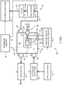
- FIG. 1 shows an example structure of a secondary battery testing system according to an embodiment of the present disclosure.
- a secondary battery which is a target of the test is, for example, a chargeable lithium-ion battery.
- secondary battery testing system of the embodiment of the present disclosure with the structures described below, secondary batteries of various types and various sizes can be tested.
- a secondary battery testing system 10 comprises a secondary battery testing apparatus 12, a vacuum pump 14, a purge gas tank 16, a mass flow controller 18, a trap apparatus 19, a mass spectrometer 24, a charge/discharge testing machine 25, a control apparatus 26, and other components.
- the secondary battery testing apparatus 12 has a sealed container 28.
- An internal space 30 of the sealed container 28 is an airtight space.
- a secondary battery 32 is placed in the internal space 30.
- the secondary battery 32 is detachably fixed on a bottom plate of the sealed container 28 by a fixing device 34.
- a release port 36, an introduction port 38, and a release port 40 are provided on the sealed container 28.
- the release ports 36 and 40 are release outlets.
- the introduction port 38 is an introduction inlet.
- the vacuum pump 14 is connected to the release port 36.
- the purge gas tank 16 is connected to the introduction port 38 via the mass flow controller 18.
- the mass spectrometer 24 is connected to the release port 40 via the trap apparatus 19.
- the vacuum pump 14 is an apparatus for removing internal gas such as air from inside of the sealed container 28, to form a vacuum therein.
- the purge gas tank 16 is filled with an inert gas such as helium gas or argon gas, serving as a purge gas. After a vacuum is formed in the sealed container 28, the purge gas is sent to the inside of the sealed container 28. In this process, a flow rate of the purge gas is controlled by the mass flow controller 18. As will be described later, after the introduction of the purge gas is started, an opening is formed on an outer housing of the secondary battery. Gas existing in the secondary battery 32 leaks through the opening, or gas is generated from contents leaking through the opening.
- the gas released from the release port 40 is sent to the mass spectrometer 24 serving as a gas measurement apparatus, through the trap apparatus 19.
- the mass spectrometer 24 is formed from an ion source, a mass analyzer, an ion detector, an information processing apparatus, and other components. With the mass spectrometer 24, a mass spectrum of the gas is produced. Based on the mass spectrum, one or a plurality of components included in the gas are specified. Alternatively, a gas chromatograph or the like may be provided between the secondary battery testing apparatus 12 and the mass spectrometer 24.
- the trap apparatus 19 has a buffer tank 20 and a filter 22 which are connected in series.
- a tube 44 is provided between the release port 40 of the sealed container 28 and an introduction port of the buffet tank 20
- a tube 46 is provided between a release port of the buffer tank 20 and an introduction port of the filter 22
- a tube 50 is provided between a release port of the filter 22 and the mass spectrometer 24.
- Each of the tubes 44, 46, and 50 is, for example, a capillary tube.
- a pressure sensor S for detecting a pressure inside the tank is provided on the buffer tank 20 and a filter 22 which are connected in series.
- a tube 44 is provided between the release port 40 of the sealed container 28 and an introduction port of the buffet tank 20
- a tube 46 is provided between a release port of the buffer tank 20 and an introduction port of the filter 22
- a tube 50 is provided between a release port of the filter 22 and the mass spectrometer 24.
- Each of the tubes 44, 46, and 50 is, for example, a
- the control apparatus 26 is formed from an information processing apparatus such as a computer.
- the control apparatus 26 controls operations of various elements of the secondary battery testing system 10.
- a detection signal from the pressure sensor S is input to the control apparatus 26.
- the information processing apparatus in the mass spectrometer 24 may function as the control apparatus 26.
- the operations of various elements of the secondary battery testing system 10 may be manually switched.
- the secondary battery testing apparatus 12 comprises a first tool unit 56 and a second tool unit 58 provided on the sealed container 28.
- the first tool unit 56 is formed from a first tool 60 and a first holder 62.
- the second tool unit 58 is formed from a second tool and a second holder.
- the first tool unit 56 and the second tool unit 58 are selectively used. The tool units will be described later in detail.
- a first terminal (first relay terminal) 52 and a second terminal (second relay terminal) 54 are provided on the sealed container 28.
- One terminal of the secondary battery 32 is electrically connected to the first terminal 52 via a cable 64, and the other terminal of the secondary battery 32 is electrically connected to the second terminal 54 via a cable 66.
- the first terminal 52 and the second terminal 54 are electrically connected to the charge/discharge testing machine 25 via cables 68 and 70, respectively.
- the charge/discharge testing machine 25 is used as necessary, and controls charging and discharging of the secondary battery. Gases released from the secondary battery during the processes of charging and discharging the secondary battery are measured.
- elements other than the secondary battery testing apparatus 12 are used as necessary or are provided as necessary.
- another measurement apparatus may be placed.
- other devices may be added to the secondary battery testing system 10.
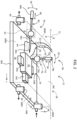
- FIG. 2 shows the configuration of the secondary battery testing apparatus 12. Elements in FIG. 2 that are identical to the elements shown in FIG. 1 are assigned the same reference numerals.
- the sealed container 28 is a container having airtightness, pressure endurance, and an electrical insulating property.
- the sealed container 28 is formed from a bottom plate 28A, a frame 28B, and a ceiling plate 28C. These members are formed from, for example, polycarbonate. All or a part of the frame 28B is transparent, and, similarly, all or a part of the ceiling plate 28C is transparent. A user can observe the secondary battery 32 in the sealed container 28 through the transparent parts.
- the frame 28B is formed from four side plates 28B1-28B4. Each of the side plates 28B1-28B4 is a vertical plate.
- the side plates 28B1 and 28B3 are orthogonal to a y direction, and the side plates 28B2 and 28B4 are orthogonal to an x direction.
- the ceiling plate 28C moves to open and close. In a closed state thereof, the ceiling plate 28C has a horizontal orientation.
- a sealing member (not shown) is provided between the ceiling plate 28C and the frame 28B. In the illustrated example configuration, the ceiling plate 28C rotates (refer to reference numeral 72) about a rotational axis C.
- a hinge is provided between the frame 28B and the ceiling plate 28C, but the hinge is not illustrated in the figures.
- a size of the sealed container 28 in the x direction is, for example, 30 cm
- a size in the y direction is, for example, 30 cm
- a size in a z direction is, for example, 5 cm.
- the secondary battery 32 is detachably fixed on the bottom plate 28A by the fixing device 34.
- the fixing device 34 is formed from a plurality of sliders 34A, 34B, and 34C.
- the secondary battery 32 is constrained by the sliders 34A, 34B, and 34C.
- the sliders 34A and 34B slide in the y direction, and the slider 34C slides in the x direction.
- the release port 36 is attached, and the introduction port 38 is attached.
- the release port 40 is attached.
- Each of the ports 36, 38, and 40 has a valve. Alternatively, any of the ports may be provided on the ceiling plate 28C.
- the terminals 52 and 54 are attached on the ceiling plate 28C.
- the terminal 52 and one terminal of the secondary battery 32 are connected with each other by the cable 64, and the terminal 54 and the other terminal of the secondary battery 32 are connected with each other by the cable 66.
- the first tool unit 56 is attached on the side plate 28B4, and the second tool unit 58 is attached on the ceiling plate 28C.
- the first tool unit 56 is formed from a first tool 60 and a first holder 62.
- the first tool 60 extends along a center axis thereof, and is, for example, a ceramic cuter having an electrical insulating property.
- the first tool 60 is formed from a tip part 60a, a handle 60b, and an intermediate part 60c.
- the tip part 60a is a sharp portion for forming an opening on the outer housing of the secondary battery 32 in the sealed container 28.
- the tip part 60a has a steeple shape, a tapered shape, a circular conical shape, or the like. Alternatively, a knife shape may be employed as the form of the tip part 60a.
- the handle 60b is a bar-shaped portion manipulated by the user outside the sealed container 28.
- the part between the tip part 60a and the handle 60b is the intermediate part 60c, which corresponds to a shaft.
- the intermediate part 60c is held by the first holder 62.
- the first holder 62 is a structure which holds the first tool 60 while maintaining the airtightness of the sealed container 28, and while allowing an advancing/retreating movement and a tilting movement of the first tool 60.
- the first holder 62 is fixed on the side plate 28B4.
- the first holder 62 has a ball-joint structure. This structure will be described later in detail.
- a terminal surface (primary surface) of the secondary battery 32 opposes an inner surface of the side plate 28B4.
- a center axis of the first holder 62 is orthogonal to the side plate 28B4. In other words, the center axis of the first holder 62 is parallel to the x direction.
- the center axis of the first holder 62 passes through a region near a center part of the terminal surface of the secondary battery 32.
- the advancing/retreating movement of the first tool 60 is a movement along the center axis of the first tool 60.
- the tilting movement of the first tool 60 is a movement to tilt or rotate the center axis of the first tool 60 with respect to the center axis of the first holder 62.
- the first tool 60 can be freely tilted in the y direction and the z direction.
- the handle 60b is manipulated; that is, the orientation of the first tool 60 is determined (refer to reference numeral 78), so as to direct the tip part 60a toward a target position on the outer housing of the secondary battery 32. Then, the handle 60b is pressed so that the tip part 60a reaches the target position (refer to reference numeral 80). With a forward movement of the first tool 60, while the tip part 60a is piercing the target position, an opening (a hole or a cleavage) is formed on the outer housing of the secondary battery 32.
- the tip part 60a may be laterally moved, to form a slit on the outer housing of the secondary battery 32. From the opening formed by the first tool 60, the contents of the secondary battery leak.
- the contents include gas.
- gas is generated from the leaked contents.
- the gas is a measurement target or an analysis target.
- the second tool unit 58 is provided at a position distanced from the first tool unit 56.
- the second tool unit 58 has a structure similar to that of the first tool unit 56.
- the second tool unit 58 is formed from a second tool 74 and a second holder 76.
- the second tool 74 extends along a center axis thereof, and is, for example, a ceramic cutter.
- the second tool 74 is formed from a tip part 74a, a handle 74b, and an intermediate part 74c.
- the tip part 74a is a sharp portion for forming an opening on the outer housing of the secondary battery 32 in the sealed container 28.
- a shape of the tip part 74a is identical to the shape of the tip part 60a. Alternatively, different shapes may be employed for the two tip parts 60a and 74a.
- the handle 74b is a part manipulated by the user outside the sealed container 28. A part between the tip part 74a and the handle 74b is the intermediate part 74c. The intermediate part 74c is held by the second holder 76.
- the second holder 76 is a structure which holds the second tool 74 while maintaining the airtightness of the sealed container 28 and while allowing an advancing/retreating movement and a tilting movement of the second tool 74.
- the second holder 76 is attached to the ceiling plate 28C.
- the second holder 76 has a ball-joint structure.
- a particular side surface of the secondary battery 32 (an upper surface in FIG. 2 ) opposes an inner surface of the ceiling plate 28C.
- a center axis of the second holder 76 is orthogonal to the ceiling plate 28C, and is parallel to the z direction.
- the center axis of the second holder 76 passes through a region near an end of a particular side surface of the secondary battery 32 (a part near the primary surface).
- the advancing/retreating movement of the second tool 74 is a movement along a center axis of the second tool 74 (refer to reference numeral 84).
- the tilting movement of the second tool 74 is a movement to tilt the center axis of the second tool 74 with respect to the center axis of the second holder 76 (refer to reference numeral 82).
- the second tool 74 may be freely tilted in the x direction and the y direction.
- a manipulation method of the second tool 74 is similar to the manipulation method of the first tool 60.
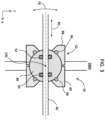
- FIG. 3 shows a structure of the first tool unit 56.
- the second tool unit also has a structure similar to the structure shown in FIG. 3 .
- the first holder 62 holds the first tool while maintaining the airtightness of the sealed container and while allowing an advancing/retreating movement and a tilting movement of the first tool 60. More specifically, the first holder 62 has a ball 86, an outer casing 88, and an inner casing 90. The ball 86 has a through hole. The intermediate part of the first tool 60 is inserted through the through hole. In the through hole, O rings 92 and 94 are placed. The O rings are sealing members for maintaining the airtightness during the advancing/retreating movement of the first tool 60.
- the outer casing 88 and the inner casing 90 are members which hold the ball 86 in a rotatable manner.
- An O ring 96 is placed in the outer casing 88, and an O ring 98 is placed in the inner casing 90.
- the O rings 96 and 98 are sealing members for maintaining the airtightness during the tilting movement of the first tool 60; that is, a rotational movement of the ball 86.
- Reference numeral 80 shows the advancing/retreating movement of the first tool 60.
- Reference numeral 78 shows the tilting movement of the first tool 60.
- Reference numeral 100 shows an origin for the tilting movement (rotational movement) of the first tool 60. The origin 100 coincides with the center of the ball 86.
- the first holder 62 has an airtight structure and a ball-joint structure. With this configuration, the airtightness of the sealed container is maintained during the movement of the first tool 60, and a space which the tip part of the first tool 60 can reach is enlarged.
- other structures may be employed as the structure of the first holder 62.
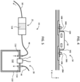
- FIG. 4 shows a specific example structure of the fixing device 34.
- the secondary battery 32 is placed on the bottom plate 28A.
- the fixing device 34 has three sliders, including the sliders 34A and 34B (the slider 34C does not appear in FIG. 4 ).
- the sliders 34A and 34B are formed respectively from metal fittings 102 and 104 having an L shape, and slide pins 106 and 108. Each of the slide pins 106 and 108 is a screw or a bolt.
- other fixing devices may be provided as the fixing device 34.
- FIG. 5 shows a specific example structure of the trap apparatus 19.
- the trap apparatus 19 is formed from the buffer tank 20 and the filter 22.
- the buffer tank 20 has a container 110 which stores liquid or solid.
- An introduction nozzle 114 and a release nozzle 116 are provided on an upper plate of the container 110.
- the tube 44 is connected to the introduction nozzle 114, and the tube 46 is connected to the release nozzle 116.
- Gas released from the sealed container is introduced via the tube 44 and the introduction nozzle 114 into an inside 112 of the container 110.
- the gas is sent from the inside 112 via the release nozzle 116 to the tube 46.
- the inside of the mass spectrometer is at a negative pressure, and the gas in the sealed container flows from the sealed container via the trap apparatus 19 to the mass spectrometer. Such a flow of gas is accelerated by the purge gas.
- the pressure sensor S is provided on the upper plate. A pressure of the inside 112 is detected by the pressure sensor S. Based on a detection signal of the pressure sensor S, storage of a certain amount of contents in the container 110 is judged. Alternatively, clogging of the tube may be judged based on the detection signal of the pressure sensor S.
- the filter 22 has a quartz glass fiber (quarts glass wool). Solid particles and liquid drops are trapped with the quartz glass fiber. Alternatively, other filters may be provided as the filter 22.
- the tube 46 is provided between the buffer tank 20 and the filter 22.
- the tube 50 is provided between the filter 22 and the mass spectrometer.
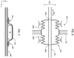
- FIG. 6 shows another example structure of the tool unit.
- a tool unit 120 may be used as the first tool unit or the second tool unit.
- the tool unit 120 is formed from a tool 122 and a holder 124.
- the tool 122 is, for example, a ceramic cutter.
- the holder 124 is fixed on a side plate or a ceiling plate 125.
- the holder 124 is formed from an outer bellows 124A and an inner bellows 124B.
- Each of the outer bellows 124A and the inner bellows 124B has a plurality of structural units of connected structures. Each structural unit is a connected structure of a mountain fold and a valley fold.
- Openings 130a and 130b are respectively formed on the outer bellows 124A and the inner bellows 124B, and the tool 122 passes through these openings 130a and 130b.
- the two openings 130a and 130b and the tool 122 are adhered with each other, so as to secure airtightness.
- the outer bellows 124A and the inner bellows 124B expand or retract (refer to reference numerals 126 to 129).
- the outer bellows 124A and the inner bellows 124B deform (including expansion and contraction) (refer to reference numerals 126 to 129).
- the holder 124 has a bellows structure, and holds the tool 122 while maintaining the airtightness of the sealed container, while allowing the advancing/retreating movement and the tilting movement of the tool 122.
- FIG. 7 shows another example of the fixing device.
- the secondary battery 32 is placed on the bottom plate 28A.
- the fixing device has a band 134 and pins 136 and 138. Respective ends of the band 134 are fixed by the pins 136 and 138.
- the band 134 has flexibility and elasticity. As illustrated, the band 134 covers the secondary battery 32, and the secondary battery 32 is constrained by the band 134.
- FIG. 8 shows a first example method of testing a secondary battery according to an embodiment of the present disclosure.
- a plurality of devices are connected to the secondary battery testing apparatus.
- three valves respectively provided on the two release ports and the introduction port are closed.
- the secondary battery is fixed in the sealed container.
- two terminals of the secondary battery and two relay terminals are connected with each other by two cables.
- an airtight state of the sealed container is formed.
- the valve in the release port for suctioning is opened, and an operation of the vacuum pump is started. With this process, air in the sealed container is suctioned, and, ultimately, the inside of the sealed container is set to a vacuum state. After the formation of the vacuum state, the valve in the release port for suctioning is closed, and the operation of the vacuum pump is stopped.
- valve in the release port for gas release is opened, and gas release is started.
- valve in the introduction port is opened, and the purge gas is introduced into the sealed container.
- the flow rate of the purge gas is adjusted by the mass flow controller.
- S20 may be executed prior to S18.
- background measurement is performed prior to the gas measurement. More specifically, the components included in the atmospheric air are measured with the mass spectrometer. After the detection values of these components are stabilized, the gas measurement described below is started.
- one of the first tool unit and the second tool unit is selected by the user.
- the tool unit to be used is selected according to an opening formation position (target position) on the outer housing of the secondary battery in the sealed container.
- the user uses the selected tool unit, to form an opening on the outer housing of the secondary battery. Through this opening, gas in the secondary battery leaks, or the contents in the secondary battery leak. Gas is generated from the leaked contents.
- the gas released in the sealed container is mass-analyzed by the mass spectrometer. Specifically, a mass spectrum of the gas is produced. Based on the mass spectrum, one or a plurality of components included in the gas are specified.
- S28 and S30 are executed.
- the charge/discharge test is started by the charge/discharge testing machine. For example, first, a charge period is set, and then, a discharge period is set. The gas generated during the charge period and the gas generated during the discharge period are analyzed through a method similar to that described above.
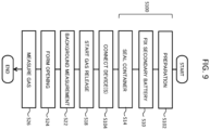
- FIG. 9 shows a second example method of testing a secondary battery according to the embodiment of the present disclosure.
- a glove box is used.
- S100 shows a plurality of steps executed using the glove box.
- a secondary battery testing apparatus (more specifically, the sealed container) and the secondary battery are placed in the glove box.
- the inside of the glove box is filled with an inert gas (for example, argon gas).
- an inert gas for example, argon gas.
- the secondary battery is fixed in the sealed container.
- the inside of the sealed container is set in the airtight state.
- the sealed container is taken out of the glove box, and then, the devices shown in FIG. 1 are connected to the sealed container.
- release of gas from the sealed container is started, and in S22, the background measurement is performed.
- S24 using a selected tool unit, an opening is formed on the outer housing of the secondary battery. Gas generated with this process is measured in S26.
- the opening is formed on the outer housing of the secondary battery after the background measurement and before the charge/discharge test of the secondary battery.
- the opening may be formed on the outer housing of the secondary battery after the background measurement and after the charge/discharge test of the secondary battery.
- the gas released through the opening is analyzed by the mass spectrometer.
- secondary batteries of various sizes and various forms may be tested.
- an opening may be formed at a desired site on the outer housing of the secondary battery.
- a secondary battery testing apparatus having superior general-purpose property can be provided.
- other tests of secondary batteries and primary batteries may be performed using the above-described structure.
Landscapes
- Chemical & Material Sciences (AREA)
- Chemical Kinetics & Catalysis (AREA)
- Electrochemistry (AREA)
- General Chemical & Material Sciences (AREA)
- Engineering & Computer Science (AREA)
- Manufacturing & Machinery (AREA)
- Analytical Chemistry (AREA)
- Health & Medical Sciences (AREA)
- Life Sciences & Earth Sciences (AREA)
- Molecular Biology (AREA)
- Biomedical Technology (AREA)
- Physics & Mathematics (AREA)
- Biochemistry (AREA)
- General Health & Medical Sciences (AREA)
- General Physics & Mathematics (AREA)
- Immunology (AREA)
- Pathology (AREA)
- Secondary Cells (AREA)
- Tests Of Electric Status Of Batteries (AREA)
- Other Investigation Or Analysis Of Materials By Electrical Means (AREA)
- Battery Mounting, Suspending (AREA)
Abstract
Description
- The present disclosure relates to a secondary battery testing apparatus and a secondary battery testing system, and in particular to a system which measures gas generated by a secondary battery.
- Various secondary battery testing apparatuses have been proposed. Each of these secondary battery testing apparatuses performs tests on a particular type of secondary battery. Realization of a secondary battery testing apparatus having a general-purpose property; that is, a secondary battery testing apparatus which can perform tests on secondary batteries of various sizes or of various types, is desired.
- A secondary battery testing apparatus has a tool for forming an opening such as a cut or a hole on an outer housing of the secondary battery. In the secondary battery test, a gas leaking from the opening or a gas generated from contents leaking from the opening is analyzed.
Documents 1, 2, and 3 disclose apparatuses for testing a primary battery or a secondary battery. All of these apparatuses have a tool for forming an opening on an outer housing of the battery. In all of these tools, only an advancing/retreating movement is allowed. - In the secondary battery test, an opening must be formed at an appropriate position on the outer housing of the secondary battery. The appropriate position is, for example, a position where electrical short-circuiting can be avoided, or a position at which release of gas can be expected. In realizing the secondary battery testing apparatus having the general-purpose property, realization of a tool which can form an opening at a desired position on the outer housing of the secondary battery is desired.
-
- [Document 1]
JP 2002-313437 A - [Document 2]
JP H6-186007 A - [Document 3] Kazuma Kumai et al., Gas generation mechanism due to electrolyte decomposition in commercial lithium-ion cell, Journal of Power Sources, 81-82, 1999, pp. 715-719
- An advantage of the present disclosure lies in provision of a secondary battery testing apparatus which can perform tests of secondary batteries having various sizes or various forms. Alternatively, another advantage of the present disclosure lies in provision of a secondary battery testing apparatus which can form an opening at a desired position on an outer housing of the secondary battery.
- According to one aspect of the present disclosure, there is provided a secondary battery testing apparatus comprising: a sealed container; a fixing device that detachably fixes a secondary battery in the sealed container; a first tool that has a first tip part which forms an opening on an outer housing of the secondary battery in the sealed container, and a first handle manipulated by a user outside the sealed container; a first holder provided on the sealed container, that holds the first tool while maintaining airtightness of the sealed container, and while allowing an advancing/retreating movement and a tilting movement of the first tool; and a release outlet provided on the sealed container, that releases gas released from the secondary battery.
- According to another aspect of the present disclosure, there is provided a secondary battery testing system comprising: the secondary battery testing apparatus described above; a gas measurement apparatus that measures gas released from the release outlet; and a trap apparatus provided between the release outlet and the gas measurement apparatus, that traps contents released from the secondary battery other than the gas.
- Embodiment(s) of the present disclosure will be described based on the following figures, wherein:
-
FIG. 1 is a diagram showing a secondary battery testing system according to an embodiment of the present disclosure; -
FIG. 2 is a diagram showing the secondary battery testing apparatus according to the embodiment; -
FIG. 3 is a diagram showing an example of a holder; -
FIG. 4 is a diagram showing an example of a fixing device; -
FIG. 5 is a diagram showing an example of a trap apparatus; -
FIG. 6 is a diagram showing another example of the holder; -
FIG. 7 is a diagram showing another example of the fixing device; -
FIG. 8 is a diagram showing a first example method of testing a secondary battery according to an embodiment of the present disclosure; and -
FIG. 9 is a diagram showing a second example method of testing a secondary battery according to the embodiment of the present disclosure. - An embodiment of the present disclosure will now be described with reference to the drawings.
- A secondary battery testing apparatus according to an embodiment of the present disclosure comprises a sealed container, a fixing device, a first tool, a first holder, and a release outlet. The fixing device is a device which detachably fixes a secondary battery in the sealed container. The first tool has a first tip part which forms an opening on an outer housing of the secondary battery in the sealed container, and a first handle manipulated by a user outside the sealed container. The first holder is provided on the sealed container, and holds the first tool while maintaining airtightness of the sealed container, while allowing an advancing/retreating movement and a tilting movement of the first tool. The release outlet is provided on the sealed container, and releases gas released from the secondary battery.
- According to the structure described above, because the tilting movement of the first tool is allowed in addition to the advancing/retreating movement of the first tool, an opening can be formed over a wide range on the outer housing of the secondary battery fixed in the sealed container. For example, the opening may be formed approximately perpendicular to a direction of layering of electrodes in the secondary battery (direction of alternate layering of a plurality of positive electrodes and a plurality of negative electrodes), so as to achieve advantages that short-circuiting between the positive and negative electrodes due to formation of the opening can be avoided, and that a charge/discharge test of the secondary battery can be performed even after the formation of the opening.
- Each of the first tool and the first holder has a virtual center axis. The advancing/retreating movement of the first tool is a movement along the center axis of the first tool. The tilting movement of the first tool is a movement to tilt (or rotate) the center axis of the first tool with respect to the center axis of the first holder. The tilting movement of the first tool results in an oscillating movement or a swinging movement of the first tool.
- By forming an opening on the outer housing of the secondary battery in a state in which the secondary battery is housed in the sealed container, mixing of the gas generated from the secondary battery with atmospheric air can be avoided. Alternatively, a direction or an orientation of the secondary battery may be selected during fixation of the secondary battery by the fixing device. In an embodiment of the present disclosure, the fixing device has a sliding structure, an expanding/contracting structure, a flexible fixing member, or the like.
- A secondary battery testing apparatus according to an embodiment of the present disclosure further comprises a second tool and a second holder. The second tool has a second tip part which forms an opening on the outer housing of the secondary battery in the sealed container, and a second handle manipulated by the user outside the sealed container. The second holder is provided on the sealed container at a position distanced from the first holder, and holds the second tool while maintaining airtightness of the sealed container, while allowing an advancing/retreating movement and a tilting movement of the second tool.
- According to the structure described above, because the first tool and the second tool are provided at different positions, the opening can be formed in a wider range over the outer housing of the secondary battery fixed in the sealed container. In an embodiment of the present disclosure, the first holder and the second holder are placed in such a manner that the center axis of the first holder and a center axis of the second holder intersect each other; that is, the first holder and the second holder respectively oppose two outer surfaces of the secondary battery.
- In an embodiment of the present disclosure, the sealed container has a side plate and a ceiling plate. The first holder is provided on the side plate. The second holder is provided on the ceiling plate. For example, a first outer surface of the secondary battery fixed in the sealing container faces the side plate, and a second outer surface of the secondary battery faces the ceiling plate. In this case, an opening is formed by the first tool on the first outer surface, or an opening is formed by the second tool on the second outer surface. Normally, one opening is formed, but alternatively, a plurality of openings may be formed. Alternatively, three or more tools and three or more holders may be provided.
- Each of the second tool and the second holder has a center axis. The advancing/retreating movement of the second tool is a movement along the center axis of the second tool. The tilting movement of the second tool is a movement to tilt the center axis of the second tool with respect to the center axis of the second holder.
- In an embodiment of the present disclosure, each of the first tip part and the second tip part is formed from a non-conductive material. According to this structure, short-circuiting in the secondary battery via the tool as a medium can be prevented, and electric shock can be prevented. Alternatively, each of the tools as a whole may be formed from a non-conductive material.
- In an embodiment of the present disclosure, all or a part of the sealing container is transparent. With this structure, the secondary battery fixed in the sealed container can be observed from outside the sealed container. According to this structure, an opening can be formed on the outer housing of the secondary battery using the first tool or the second tool while observing the secondary battery.
- A secondary battery testing apparatus according to an embodiment of the present disclosure further comprises a first relay terminal, a second relay terminal, a first internal cable, and a second internal cable. The first relay terminal and the second relay terminal are provided on the sealed container. The first internal cable connects a first terminal of the secondary battery and the first realty terminal. The second internal cable connects a second terminal of the secondary battery and the second relay terminal. Each of the first relay terminal and the second relay terminal is a terminal connected to a charge/discharge testing machine. According to this structure, the charge/discharge test of the secondary battery can be performed while the secondary battery is continued to be placed in the sealed container. Gas generated during the charge/discharge test is measured.
- According to another aspect of the present disclosure, there is provided a secondary battery testing system comprising: the secondary battery testing apparatus described above; a gas measurement apparatus that measures gas released from the release outlet of the secondary battery testing apparatus; and a trap apparatus provided between the release outlet of the secondary battery testing apparatus and the gas measurement apparatus, that traps contents released from the secondary battery other than the gas. According to this structure, because the trap apparatus is provided, contamination of the gas measurement apparatus by the contents other than the gas can be prevented or reduced. The trap apparatus is an apparatus which traps liquid and solid particles.
- In an embodiment of the present disclosure, the trap apparatus comprises a buffer tank which stores the contents other than the gas, and a filter provided downstream of the buffer tank, which blocks passage of the contents other than the gas. According to this structure, because two types of traps function stepwise, the contamination of the gas measurement apparatus can be effectively prevented.
-
FIG. 1 shows an example structure of a secondary battery testing system according to an embodiment of the present disclosure. A secondary battery which is a target of the test is, for example, a chargeable lithium-ion battery. According to the secondary battery testing system of the embodiment of the present disclosure, with the structures described below, secondary batteries of various types and various sizes can be tested. - In
FIG. 1 , a secondarybattery testing system 10 comprises a secondarybattery testing apparatus 12, avacuum pump 14, apurge gas tank 16, amass flow controller 18, atrap apparatus 19, amass spectrometer 24, a charge/discharge testing machine 25, acontrol apparatus 26, and other components. - The secondary
battery testing apparatus 12 has a sealedcontainer 28. Aninternal space 30 of the sealedcontainer 28 is an airtight space. Asecondary battery 32 is placed in theinternal space 30. Specifically, thesecondary battery 32 is detachably fixed on a bottom plate of the sealedcontainer 28 by a fixingdevice 34. - A
release port 36, anintroduction port 38, and arelease port 40 are provided on the sealedcontainer 28. Therelease ports introduction port 38 is an introduction inlet. Thevacuum pump 14 is connected to therelease port 36. Thepurge gas tank 16 is connected to theintroduction port 38 via themass flow controller 18. Themass spectrometer 24 is connected to therelease port 40 via thetrap apparatus 19. - The
vacuum pump 14 is an apparatus for removing internal gas such as air from inside of the sealedcontainer 28, to form a vacuum therein. Thepurge gas tank 16 is filled with an inert gas such as helium gas or argon gas, serving as a purge gas. After a vacuum is formed in the sealedcontainer 28, the purge gas is sent to the inside of the sealedcontainer 28. In this process, a flow rate of the purge gas is controlled by themass flow controller 18. As will be described later, after the introduction of the purge gas is started, an opening is formed on an outer housing of the secondary battery. Gas existing in thesecondary battery 32 leaks through the opening, or gas is generated from contents leaking through the opening. - The gas released from the
release port 40 is sent to themass spectrometer 24 serving as a gas measurement apparatus, through thetrap apparatus 19. Themass spectrometer 24 is formed from an ion source, a mass analyzer, an ion detector, an information processing apparatus, and other components. With themass spectrometer 24, a mass spectrum of the gas is produced. Based on the mass spectrum, one or a plurality of components included in the gas are specified. Alternatively, a gas chromatograph or the like may be provided between the secondarybattery testing apparatus 12 and themass spectrometer 24. - The
trap apparatus 19 has abuffer tank 20 and afilter 22 which are connected in series. Atube 44 is provided between therelease port 40 of the sealedcontainer 28 and an introduction port of thebuffet tank 20, atube 46 is provided between a release port of thebuffer tank 20 and an introduction port of thefilter 22, and atube 50 is provided between a release port of thefilter 22 and themass spectrometer 24. Each of thetubes buffer tank 20, a pressure sensor S for detecting a pressure inside the tank is provided. - The
control apparatus 26 is formed from an information processing apparatus such as a computer. Thecontrol apparatus 26 controls operations of various elements of the secondarybattery testing system 10. A detection signal from the pressure sensor S is input to thecontrol apparatus 26. Alternatively, the information processing apparatus in themass spectrometer 24 may function as thecontrol apparatus 26. Alternatively, the operations of various elements of the secondarybattery testing system 10 may be manually switched. - The secondary
battery testing apparatus 12 according to the embodiment comprises afirst tool unit 56 and asecond tool unit 58 provided on the sealedcontainer 28. Thefirst tool unit 56 is formed from afirst tool 60 and afirst holder 62. Thesecond tool unit 58 is formed from a second tool and a second holder. Thefirst tool unit 56 and thesecond tool unit 58 are selectively used. The tool units will be described later in detail. - A first terminal (first relay terminal) 52 and a second terminal (second relay terminal) 54 are provided on the sealed
container 28. One terminal of thesecondary battery 32 is electrically connected to thefirst terminal 52 via acable 64, and the other terminal of thesecondary battery 32 is electrically connected to thesecond terminal 54 via acable 66. Thefirst terminal 52 and thesecond terminal 54 are electrically connected to the charge/discharge testing machine 25 viacables - The charge/
discharge testing machine 25 is used as necessary, and controls charging and discharging of the secondary battery. Gases released from the secondary battery during the processes of charging and discharging the secondary battery are measured. - In
FIG. 1 , elements other than the secondarybattery testing apparatus 12 are used as necessary or are provided as necessary. In place of themass spectrometer 24, another measurement apparatus may be placed. Further, other devices may be added to the secondarybattery testing system 10. -
FIG. 2 shows the configuration of the secondarybattery testing apparatus 12. Elements inFIG. 2 that are identical to the elements shown inFIG. 1 are assigned the same reference numerals. - The sealed
container 28 is a container having airtightness, pressure endurance, and an electrical insulating property. The sealedcontainer 28 is formed from abottom plate 28A, aframe 28B, and aceiling plate 28C. These members are formed from, for example, polycarbonate. All or a part of theframe 28B is transparent, and, similarly, all or a part of theceiling plate 28C is transparent. A user can observe thesecondary battery 32 in the sealedcontainer 28 through the transparent parts. - The
frame 28B is formed from four side plates 28B1-28B4. Each of the side plates 28B1-28B4 is a vertical plate. The side plates 28B1 and 28B3 are orthogonal to a y direction, and the side plates 28B2 and 28B4 are orthogonal to an x direction. - The
ceiling plate 28C moves to open and close. In a closed state thereof, theceiling plate 28C has a horizontal orientation. A sealing member (not shown) is provided between theceiling plate 28C and theframe 28B. In the illustrated example configuration, theceiling plate 28C rotates (refer to reference numeral 72) about a rotational axis C. A hinge is provided between theframe 28B and theceiling plate 28C, but the hinge is not illustrated in the figures. A size of the sealedcontainer 28 in the x direction is, for example, 30 cm, a size in the y direction is, for example, 30 cm, and a size in a z direction is, for example, 5 cm. - In the illustrated example configuration, the
secondary battery 32 is detachably fixed on thebottom plate 28A by the fixingdevice 34. The fixingdevice 34 is formed from a plurality ofsliders secondary battery 32 is constrained by thesliders sliders slider 34C slides in the x direction. - On the side plate 28B3, the
release port 36 is attached, and theintroduction port 38 is attached. On the side plate 28B4, therelease port 40 is attached. Each of theports ceiling plate 28C. - On the
ceiling plate 28C, theterminals secondary battery 32 are connected with each other by thecable 64, and the terminal 54 and the other terminal of thesecondary battery 32 are connected with each other by thecable 66. - In the illustrated example configuration, the
first tool unit 56 is attached on the side plate 28B4, and thesecond tool unit 58 is attached on theceiling plate 28C. - The
first tool unit 56 is formed from afirst tool 60 and afirst holder 62. Thefirst tool 60 extends along a center axis thereof, and is, for example, a ceramic cuter having an electrical insulating property. Thefirst tool 60 is formed from atip part 60a, ahandle 60b, and anintermediate part 60c. - The
tip part 60a is a sharp portion for forming an opening on the outer housing of thesecondary battery 32 in the sealedcontainer 28. Thetip part 60a has a steeple shape, a tapered shape, a circular conical shape, or the like. Alternatively, a knife shape may be employed as the form of thetip part 60a. Thehandle 60b is a bar-shaped portion manipulated by the user outside the sealedcontainer 28. The part between thetip part 60a and thehandle 60b is theintermediate part 60c, which corresponds to a shaft. Theintermediate part 60c is held by thefirst holder 62. - The
first holder 62 is a structure which holds thefirst tool 60 while maintaining the airtightness of the sealedcontainer 28, and while allowing an advancing/retreating movement and a tilting movement of thefirst tool 60. Thefirst holder 62 is fixed on the side plate 28B4. Thefirst holder 62 has a ball-joint structure. This structure will be described later in detail. A terminal surface (primary surface) of thesecondary battery 32 opposes an inner surface of the side plate 28B4. - A center axis of the
first holder 62 is orthogonal to the side plate 28B4. In other words, the center axis of thefirst holder 62 is parallel to the x direction. The center axis of thefirst holder 62 passes through a region near a center part of the terminal surface of thesecondary battery 32. The advancing/retreating movement of thefirst tool 60 is a movement along the center axis of thefirst tool 60. The tilting movement of thefirst tool 60 is a movement to tilt or rotate the center axis of thefirst tool 60 with respect to the center axis of thefirst holder 62. Thefirst tool 60 can be freely tilted in the y direction and the z direction. - For example, in a state in which the
first tool 60 is retracted; that is, in a state in which thefirst tool 60 is located at a position distanced from thesecondary battery 32, thehandle 60b is manipulated; that is, the orientation of thefirst tool 60 is determined (refer to reference numeral 78), so as to direct thetip part 60a toward a target position on the outer housing of thesecondary battery 32. Then, thehandle 60b is pressed so that thetip part 60a reaches the target position (refer to reference numeral 80). With a forward movement of thefirst tool 60, while thetip part 60a is piercing the target position, an opening (a hole or a cleavage) is formed on the outer housing of thesecondary battery 32. Alternatively, thetip part 60a may be laterally moved, to form a slit on the outer housing of thesecondary battery 32. From the opening formed by thefirst tool 60, the contents of the secondary battery leak. The contents include gas. Alternatively, gas is generated from the leaked contents. The gas is a measurement target or an analysis target. - The
second tool unit 58 is provided at a position distanced from thefirst tool unit 56. Thesecond tool unit 58 has a structure similar to that of thefirst tool unit 56. Specifically, thesecond tool unit 58 is formed from asecond tool 74 and asecond holder 76. Thesecond tool 74 extends along a center axis thereof, and is, for example, a ceramic cutter. Thesecond tool 74 is formed from atip part 74a, ahandle 74b, and anintermediate part 74c. - The
tip part 74a is a sharp portion for forming an opening on the outer housing of thesecondary battery 32 in the sealedcontainer 28. A shape of thetip part 74a is identical to the shape of thetip part 60a. Alternatively, different shapes may be employed for the twotip parts handle 74b is a part manipulated by the user outside the sealedcontainer 28. A part between thetip part 74a and thehandle 74b is theintermediate part 74c. Theintermediate part 74c is held by thesecond holder 76. - The
second holder 76 is a structure which holds thesecond tool 74 while maintaining the airtightness of the sealedcontainer 28 and while allowing an advancing/retreating movement and a tilting movement of thesecond tool 74. Thesecond holder 76 is attached to theceiling plate 28C. Thesecond holder 76 has a ball-joint structure. A particular side surface of the secondary battery 32 (an upper surface inFIG. 2 ) opposes an inner surface of theceiling plate 28C. - A center axis of the
second holder 76 is orthogonal to theceiling plate 28C, and is parallel to the z direction. The center axis of thesecond holder 76 passes through a region near an end of a particular side surface of the secondary battery 32 (a part near the primary surface). - The advancing/retreating movement of the
second tool 74 is a movement along a center axis of the second tool 74 (refer to reference numeral 84). The tilting movement of thesecond tool 74 is a movement to tilt the center axis of thesecond tool 74 with respect to the center axis of the second holder 76 (refer to reference numeral 82). Thesecond tool 74 may be freely tilted in the x direction and the y direction. A manipulation method of thesecond tool 74 is similar to the manipulation method of thefirst tool 60. -
FIG. 3 shows a structure of thefirst tool unit 56. The second tool unit also has a structure similar to the structure shown inFIG. 3 . - As already described, the
first holder 62 holds the first tool while maintaining the airtightness of the sealed container and while allowing an advancing/retreating movement and a tilting movement of thefirst tool 60. More specifically, thefirst holder 62 has aball 86, anouter casing 88, and aninner casing 90. Theball 86 has a through hole. The intermediate part of thefirst tool 60 is inserted through the through hole. In the through hole, O rings 92 and 94 are placed. The O rings are sealing members for maintaining the airtightness during the advancing/retreating movement of thefirst tool 60. - The
outer casing 88 and theinner casing 90 are members which hold theball 86 in a rotatable manner. AnO ring 96 is placed in theouter casing 88, and anO ring 98 is placed in theinner casing 90. The O rings 96 and 98 are sealing members for maintaining the airtightness during the tilting movement of thefirst tool 60; that is, a rotational movement of theball 86. - The
outer casing 88 and theinner casing 90 are fixed on the side plate 28B4.Reference numeral 80 shows the advancing/retreating movement of thefirst tool 60.Reference numeral 78 shows the tilting movement of thefirst tool 60.Reference numeral 100 shows an origin for the tilting movement (rotational movement) of thefirst tool 60. Theorigin 100 coincides with the center of theball 86. - The
first holder 62 has an airtight structure and a ball-joint structure. With this configuration, the airtightness of the sealed container is maintained during the movement of thefirst tool 60, and a space which the tip part of thefirst tool 60 can reach is enlarged. Alternatively, other structures may be employed as the structure of thefirst holder 62. -
FIG. 4 shows a specific example structure of the fixingdevice 34. Thesecondary battery 32 is placed on thebottom plate 28A. As already described, the fixingdevice 34 has three sliders, including thesliders slider 34C does not appear inFIG. 4 ). Thesliders metal fittings device 34. -
FIG. 5 shows a specific example structure of thetrap apparatus 19. Thetrap apparatus 19 is formed from thebuffer tank 20 and thefilter 22. Thebuffer tank 20 has acontainer 110 which stores liquid or solid. Anintroduction nozzle 114 and arelease nozzle 116 are provided on an upper plate of thecontainer 110. Thetube 44 is connected to theintroduction nozzle 114, and thetube 46 is connected to therelease nozzle 116. - Gas released from the sealed container is introduced via the
tube 44 and theintroduction nozzle 114 into an inside 112 of thecontainer 110. The gas is sent from the inside 112 via therelease nozzle 116 to thetube 46. The inside of the mass spectrometer is at a negative pressure, and the gas in the sealed container flows from the sealed container via thetrap apparatus 19 to the mass spectrometer. Such a flow of gas is accelerated by the purge gas. - When liquid or solid is introduced to the inside 112 of the
container 110, such contents remain in the inside 112. The pressure sensor S is provided on the upper plate. A pressure of the inside 112 is detected by the pressure sensor S. Based on a detection signal of the pressure sensor S, storage of a certain amount of contents in thecontainer 110 is judged. Alternatively, clogging of the tube may be judged based on the detection signal of the pressure sensor S. - The
filter 22 has a quartz glass fiber (quarts glass wool). Solid particles and liquid drops are trapped with the quartz glass fiber. Alternatively, other filters may be provided as thefilter 22. Thetube 46 is provided between thebuffer tank 20 and thefilter 22. Thetube 50 is provided between thefilter 22 and the mass spectrometer. -
FIG. 6 shows another example structure of the tool unit. Atool unit 120 may be used as the first tool unit or the second tool unit. Thetool unit 120 is formed from atool 122 and aholder 124. Thetool 122 is, for example, a ceramic cutter. - The
holder 124 is fixed on a side plate or aceiling plate 125. Theholder 124 is formed from an outer bellows 124A and an inner bellows 124B. Each of theouter bellows 124A and theinner bellows 124B has a plurality of structural units of connected structures. Each structural unit is a connected structure of a mountain fold and a valley fold.Openings outer bellows 124A and the inner bellows 124B, and thetool 122 passes through theseopenings openings tool 122 are adhered with each other, so as to secure airtightness. - With the advancing/retreating movement of the tool 122 (refer to reference numeral 134), the
outer bellows 124A and the inner bellows 124B expand or retract (refer to referencenumerals 126 to 129). With the tilting movement of the tool 122 (refer to reference numeral 133), theouter bellows 124A and the inner bellows 124B deform (including expansion and contraction) (refer to referencenumerals 126 to 129). In this manner, theholder 124 has a bellows structure, and holds thetool 122 while maintaining the airtightness of the sealed container, while allowing the advancing/retreating movement and the tilting movement of thetool 122. -
FIG. 7 shows another example of the fixing device. Thesecondary battery 32 is placed on thebottom plate 28A. The fixing device has aband 134 and pins 136 and 138. Respective ends of theband 134 are fixed by thepins band 134 has flexibility and elasticity. As illustrated, theband 134 covers thesecondary battery 32, and thesecondary battery 32 is constrained by theband 134. -
FIG. 8 shows a first example method of testing a secondary battery according to an embodiment of the present disclosure. As shown inFIG. 1 , a plurality of devices are connected to the secondary battery testing apparatus. In an initial state, three valves respectively provided on the two release ports and the introduction port are closed. - In S10, the secondary battery is fixed in the sealed container. In S12, two terminals of the secondary battery and two relay terminals are connected with each other by two cables. Then, in S14, an airtight state of the sealed container is formed. In S16, the valve in the release port for suctioning is opened, and an operation of the vacuum pump is started. With this process, air in the sealed container is suctioned, and, ultimately, the inside of the sealed container is set to a vacuum state. After the formation of the vacuum state, the valve in the release port for suctioning is closed, and the operation of the vacuum pump is stopped.
- In S18, the valve in the release port for gas release is opened, and gas release is started. In S20, the valve in the introduction port is opened, and the purge gas is introduced into the sealed container. In this process, the flow rate of the purge gas is adjusted by the mass flow controller. Alternatively, S20 may be executed prior to S18. In S22, background measurement is performed prior to the gas measurement. More specifically, the components included in the atmospheric air are measured with the mass spectrometer. After the detection values of these components are stabilized, the gas measurement described below is started.
- Specifically, in S24, first, one of the first tool unit and the second tool unit is selected by the user. Normally, the tool unit to be used is selected according to an opening formation position (target position) on the outer housing of the secondary battery in the sealed container. The user uses the selected tool unit, to form an opening on the outer housing of the secondary battery. Through this opening, gas in the secondary battery leaks, or the contents in the secondary battery leak. Gas is generated from the leaked contents.
- In S26, the gas released in the sealed container is mass-analyzed by the mass spectrometer. Specifically, a mass spectrum of the gas is produced. Based on the mass spectrum, one or a plurality of components included in the gas are specified.
- When it is desired to measure the gas which is generated during charging or discharging, S28 and S30 are executed. In S28, the charge/discharge test is started by the charge/discharge testing machine. For example, first, a charge period is set, and then, a discharge period is set. The gas generated during the charge period and the gas generated during the discharge period are analyzed through a method similar to that described above.
-
FIG. 9 shows a second example method of testing a secondary battery according to the embodiment of the present disclosure. In the second example method, a glove box is used. S100 shows a plurality of steps executed using the glove box. - In S102, a secondary battery testing apparatus (more specifically, the sealed container) and the secondary battery are placed in the glove box. The inside of the glove box is filled with an inert gas (for example, argon gas). In S10, the secondary battery is fixed in the sealed container. In S14, the inside of the sealed container is set in the airtight state.
- In S104, the sealed container is taken out of the glove box, and then, the devices shown in
FIG. 1 are connected to the sealed container. In S18, release of gas from the sealed container is started, and in S22, the background measurement is performed. In S24, using a selected tool unit, an opening is formed on the outer housing of the secondary battery. Gas generated with this process is measured in S26. - In the example methods illustrated in
FIGs. 8 and9 , the opening is formed on the outer housing of the secondary battery after the background measurement and before the charge/discharge test of the secondary battery. Alternatively, the opening may be formed on the outer housing of the secondary battery after the background measurement and after the charge/discharge test of the secondary battery. In this case also, the gas released through the opening is analyzed by the mass spectrometer. - According to the embodiment described above, secondary batteries of various sizes and various forms may be tested. In addition, an opening may be formed at a desired site on the outer housing of the secondary battery. Thus, a secondary battery testing apparatus having superior general-purpose property can be provided. Alternatively, other tests of secondary batteries and primary batteries may be performed using the above-described structure.
Claims (8)
- A secondary battery testing apparatus (12) comprising:a sealed container (28);a fixing device (34) that detachably fixes a secondary battery in the sealed container (28);a first tool (60) that has a first tip part which forms an opening on an outer housing of the secondary battery in the sealed container (28), and a first handle manipulated by a user outside the sealed container (28);a first holder (62) provided on the sealed container (28), that holds the first tool while maintaining airtightness of the sealed container (28), while allowing an advancing/retreating movement and a tilting movement of the first tool; anda release outlet (40) provided on the sealed container (28), that releases gas released from the secondary battery.
- The secondary battery testing apparatus (12) according to claim 1, further comprising:a second tool (74) that has a second tip part which forms an opening on the outer housing of the secondary battery in the sealed container (28), and a second handle manipulated by the user outside the sealed container (28); anda second holder (76) provided on the sealed container (28) at a position distanced from the first holder, that holds the second tool while maintaining airtightness of the sealed container (28), while allowing an advancing/retreating movement and a tilting movement of the second tool.
- The secondary battery testing apparatus (12) according to claim 2, whereinthe sealed container (28) has a side plate and a ceiling plate,the first holder (62) is provided on the side plate, andthe second holder (76) is provided on the ceiling plate.
- The secondary battery testing apparatus (12) according to claim 2 or 3, wherein
each of the first tip part and the second tip part is formed from a non-conductive material. - The secondary battery testing apparatus (12) according to any preceding claim, wherein
all or a part of the sealed container (28) is transparent, and the secondary battery fixed in the sealed container (28) can be observed from outside the sealed container (28). - The secondary battery testing apparatus (12) according to any preceding claim, further comprising:a first relay terminal (52) provided on the sealed container (28);a second relay terminal (54) provided on the sealed container (28);a first internal cable (64) that connects a first terminal of the secondary battery and the first relay terminal; anda second internal cable (66) that connects a second terminal of the secondary battery and the second relay terminal, whereineach of the first relay terminal (52) and the second relay terminal (54) is a terminal connected to a charge/discharge testing machine (25).
- A secondary battery testing system (10) comprising:the secondary battery testing apparatus (12) according to any preceding claim;a gas measurement apparatus (24) that measures gas released from the release outlet (40); anda trap apparatus (19) provided between the release outlet (40) and the gas measurement apparatus (40), that traps contents released from the secondary battery other than the gas.
- The secondary battery testing system (10) according to claim 7, wherein
the trap apparatus (19) comprises:a buffer tank (20) which stores the contents other than the gas; anda filter (22) provided downstream of the buffer tank (20), which blocks passage of the contents other than the gas.
Applications Claiming Priority (1)
| Application Number | Priority Date | Filing Date | Title |
|---|---|---|---|
| JP2023113632A JP7700176B2 (en) | 2023-07-11 | 2023-07-11 | Secondary battery test device and secondary battery test system |
Publications (2)
| Publication Number | Publication Date |
|---|---|
| EP4492506A1 true EP4492506A1 (en) | 2025-01-15 |
| EP4492506B1 EP4492506B1 (en) | 2026-02-04 |
Family
ID=91853207
Family Applications (1)
| Application Number | Title | Priority Date | Filing Date |
|---|---|---|---|
| EP24186644.1A Active EP4492506B1 (en) | 2023-07-11 | 2024-07-04 | Secondary battery testing apparatus and secondary battery testing system |
Country Status (3)
| Country | Link |
|---|---|
| US (1) | US20250022701A1 (en) |
| EP (1) | EP4492506B1 (en) |
| JP (1) | JP7700176B2 (en) |
Citations (4)
| Publication number | Priority date | Publication date | Assignee | Title |
|---|---|---|---|---|
| JPH06186007A (en) | 1992-09-09 | 1994-07-08 | Ngk Insulators Ltd | Analyzing method for gas in closed vessel and gas extracting jig |
| JP2002313437A (en) | 2001-04-10 | 2002-10-25 | Asahi Kasei Corp | Method and apparatus for measuring gas amount in sealed battery |
| JP2011003513A (en) * | 2009-06-22 | 2011-01-06 | Kobelco Kaken:Kk | Safety evaluation testing method and testing device for the same |
| CN105510174A (en) * | 2014-09-23 | 2016-04-20 | 宁德时代新能源科技股份有限公司 | Apparatus and method for detecting gas inside battery |
Family Cites Families (4)
| Publication number | Priority date | Publication date | Assignee | Title |
|---|---|---|---|---|
| JP5196534B2 (en) | 2007-12-17 | 2013-05-15 | Necカシオモバイルコミュニケーションズ株式会社 | Batteries and electronic devices |
| JP2015072266A (en) * | 2013-09-05 | 2015-04-16 | 株式会社山本金属製作所 | Safety testing method and device therefor |
| CN109935919B (en) | 2017-12-19 | 2022-05-17 | 中国科学院物理研究所 | A gas collection device for batteries |
| KR102397294B1 (en) | 2019-04-26 | 2022-05-11 | 주식회사 엘지에너지솔루션 | Apparatus for collecting secondary cell internal gas |
-
2023
- 2023-07-11 JP JP2023113632A patent/JP7700176B2/en active Active
-
2024
- 2024-07-04 EP EP24186644.1A patent/EP4492506B1/en active Active
- 2024-07-10 US US18/768,255 patent/US20250022701A1/en active Pending
Patent Citations (4)
| Publication number | Priority date | Publication date | Assignee | Title |
|---|---|---|---|---|
| JPH06186007A (en) | 1992-09-09 | 1994-07-08 | Ngk Insulators Ltd | Analyzing method for gas in closed vessel and gas extracting jig |
| JP2002313437A (en) | 2001-04-10 | 2002-10-25 | Asahi Kasei Corp | Method and apparatus for measuring gas amount in sealed battery |
| JP2011003513A (en) * | 2009-06-22 | 2011-01-06 | Kobelco Kaken:Kk | Safety evaluation testing method and testing device for the same |
| CN105510174A (en) * | 2014-09-23 | 2016-04-20 | 宁德时代新能源科技股份有限公司 | Apparatus and method for detecting gas inside battery |
Non-Patent Citations (1)
| Title |
|---|
| KAZUMA KUMAI ET AL.: "Gas generation mechanism due to electrolyte decomposition in commercial lithium-ion cell", JOURNAL OF POWER SOURCES, vol. 81-82, 1999, pages 715 - 719, XP004363249, DOI: 10.1016/S0378-7753(98)00234-1 |
Also Published As
| Publication number | Publication date |
|---|---|
| JP2025011488A (en) | 2025-01-24 |
| EP4492506B1 (en) | 2026-02-04 |
| JP7700176B2 (en) | 2025-06-30 |
| US20250022701A1 (en) | 2025-01-16 |
Similar Documents
| Publication | Publication Date | Title |
|---|---|---|
| EP3696902B1 (en) | Apparatus and method for collecting gas | |
| EP3703176B1 (en) | Apparatus, system, and method for collecting gas generated in secondary battery | |
| EP3809512B1 (en) | Secondary-battery internal gas collecting apparatus | |
| EP1753051A2 (en) | Method and apparatus for providing a sealed container containing a detectable gas | |
| WO2018060281A1 (en) | Electrochemical cell testing device | |
| EP4492506B1 (en) | Secondary battery testing apparatus and secondary battery testing system | |
| EP4397953A1 (en) | Gas collection device | |
| CN108352556A (en) | Gas analysis unit and gas analysis system | |
| CN112213344B (en) | Determination method for lithium separation of pole piece of soft-package lithium ion battery | |
| JP6891953B2 (en) | Sample plate for PESI ion source and mass spectrometer using the sample plate | |
| EP4414683A1 (en) | Gas collection device | |
| JP7782072B2 (en) | Gas analyzers | |
| KR20190056498A (en) | A sealing-type apparatus for collecting gas filled within a chamber and a method thereof | |
| KR20240060914A (en) | Air sampling system for aircraft | |
| EP4432421A1 (en) | Gas collection device | |
| CN113376243A (en) | Full-automatic multichannel battery mass spectrometry system | |
| JP2026513398A (en) | Gas collection device | |
| WO2020009451A1 (en) | Apparatus and method for collecting gas | |
| CN120826597A (en) | Gas capture equipment and gas analysis equipment using the same |
Legal Events
| Date | Code | Title | Description |
|---|---|---|---|
| PUAI | Public reference made under article 153(3) epc to a published international application that has entered the european phase |
Free format text: ORIGINAL CODE: 0009012 |
|
| STAA | Information on the status of an ep patent application or granted ep patent |
Free format text: STATUS: THE APPLICATION HAS BEEN PUBLISHED |
|
| AK | Designated contracting states |
Kind code of ref document: A1 Designated state(s): AL AT BE BG CH CY CZ DE DK EE ES FI FR GB GR HR HU IE IS IT LI LT LU LV MC ME MK MT NL NO PL PT RO RS SE SI SK SM TR |
|
| STAA | Information on the status of an ep patent application or granted ep patent |
Free format text: STATUS: REQUEST FOR EXAMINATION WAS MADE |
|
| 17P | Request for examination filed |
Effective date: 20250319 |
|
| RIC1 | Information provided on ipc code assigned before grant |
Ipc: H01M 6/50 20060101AFI20250715BHEP Ipc: H01M 10/42 20060101ALI20250715BHEP |
|
| GRAP | Despatch of communication of intention to grant a patent |
Free format text: ORIGINAL CODE: EPIDOSNIGR1 |
|
| STAA | Information on the status of an ep patent application or granted ep patent |
Free format text: STATUS: GRANT OF PATENT IS INTENDED |
|
| INTG | Intention to grant announced |
Effective date: 20250902 |
|
| GRAS | Grant fee paid |
Free format text: ORIGINAL CODE: EPIDOSNIGR3 |
|
| GRAA | (expected) grant |
Free format text: ORIGINAL CODE: 0009210 |
|
| STAA | Information on the status of an ep patent application or granted ep patent |
Free format text: STATUS: THE PATENT HAS BEEN GRANTED |
|
| RAP3 | Party data changed (applicant data changed or rights of an application transferred) |
Owner name: JEOL LTD. |
|
| AK | Designated contracting states |
Kind code of ref document: B1 Designated state(s): AL AT BE BG CH CY CZ DE DK EE ES FI FR GB GR HR HU IE IS IT LI LT LU LV MC ME MK MT NL NO PL PT RO RS SE SI SK SM TR |
|
| REG | Reference to a national code |
Ref country code: CH Ref legal event code: F10 Free format text: ST27 STATUS EVENT CODE: U-0-0-F10-F00 (AS PROVIDED BY THE NATIONAL OFFICE) Effective date: 20260204 Ref country code: GB Ref legal event code: FG4D |
|
| REG | Reference to a national code |
Ref country code: IE Ref legal event code: FG4D |
|
| REG | Reference to a national code |
Ref country code: DE Ref legal event code: R096 Ref document number: 602024002382 Country of ref document: DE |