EP4492484A1 - Vorrichtung zur kerbung eines elektrodensubstrats einer wiederaufladbaren batterie, kerbungsverfahren und wiederaufladbare batterie damit - Google Patents
Vorrichtung zur kerbung eines elektrodensubstrats einer wiederaufladbaren batterie, kerbungsverfahren und wiederaufladbare batterie damit Download PDFInfo
- Publication number
- EP4492484A1 EP4492484A1 EP24188134.1A EP24188134A EP4492484A1 EP 4492484 A1 EP4492484 A1 EP 4492484A1 EP 24188134 A EP24188134 A EP 24188134A EP 4492484 A1 EP4492484 A1 EP 4492484A1
- Authority
- EP
- European Patent Office
- Prior art keywords
- shear
- round
- straight
- notching
- electrode
- Prior art date
- Legal status (The legal status is an assumption and is not a legal conclusion. Google has not performed a legal analysis and makes no representation as to the accuracy of the status listed.)
- Pending
Links
Images






Classifications
-
- H—ELECTRICITY
- H01—ELECTRIC ELEMENTS
- H01M—PROCESSES OR MEANS, e.g. BATTERIES, FOR THE DIRECT CONVERSION OF CHEMICAL ENERGY INTO ELECTRICAL ENERGY
- H01M4/00—Electrodes
- H01M4/02—Electrodes composed of, or comprising, active material
- H01M4/04—Processes of manufacture in general
- H01M4/043—Processes of manufacture in general involving compressing or compaction
-
- B—PERFORMING OPERATIONS; TRANSPORTING
- B26—HAND CUTTING TOOLS; CUTTING; SEVERING
- B26F—PERFORATING; PUNCHING; CUTTING-OUT; STAMPING-OUT; SEVERING BY MEANS OTHER THAN CUTTING
- B26F1/00—Perforating; Punching; Cutting-out; Stamping-out; Apparatus therefor
- B26F1/02—Perforating by punching, e.g. with relatively-reciprocating punch and bed
- B26F1/12—Perforating by punching, e.g. with relatively-reciprocating punch and bed to notch margins of work
-
- B—PERFORMING OPERATIONS; TRANSPORTING
- B21—MECHANICAL METAL-WORKING WITHOUT ESSENTIALLY REMOVING MATERIAL; PUNCHING METAL
- B21D—WORKING OR PROCESSING OF SHEET METAL OR METAL TUBES, RODS OR PROFILES WITHOUT ESSENTIALLY REMOVING MATERIAL; PUNCHING METAL
- B21D28/00—Shaping by press-cutting; Perforating
- B21D28/02—Punching blanks or articles with or without obtaining scrap; Notching
-
- B—PERFORMING OPERATIONS; TRANSPORTING
- B26—HAND CUTTING TOOLS; CUTTING; SEVERING
- B26F—PERFORATING; PUNCHING; CUTTING-OUT; STAMPING-OUT; SEVERING BY MEANS OTHER THAN CUTTING
- B26F1/00—Perforating; Punching; Cutting-out; Stamping-out; Apparatus therefor
- B26F1/02—Perforating by punching, e.g. with relatively-reciprocating punch and bed
- B26F1/14—Punching tools; Punching dies
-
- H—ELECTRICITY
- H01—ELECTRIC ELEMENTS
- H01M—PROCESSES OR MEANS, e.g. BATTERIES, FOR THE DIRECT CONVERSION OF CHEMICAL ENERGY INTO ELECTRICAL ENERGY
- H01M10/00—Secondary cells; Manufacture thereof
- H01M10/04—Construction or manufacture in general
- H01M10/0404—Machines for assembling batteries
-
- H—ELECTRICITY
- H01—ELECTRIC ELEMENTS
- H01M—PROCESSES OR MEANS, e.g. BATTERIES, FOR THE DIRECT CONVERSION OF CHEMICAL ENERGY INTO ELECTRICAL ENERGY
- H01M10/00—Secondary cells; Manufacture thereof
- H01M10/05—Accumulators with non-aqueous electrolyte
- H01M10/058—Construction or manufacture
- H01M10/0585—Construction or manufacture of accumulators having only flat construction elements, i.e. flat positive electrodes, flat negative electrodes and flat separators
-
- H—ELECTRICITY
- H01—ELECTRIC ELEMENTS
- H01M—PROCESSES OR MEANS, e.g. BATTERIES, FOR THE DIRECT CONVERSION OF CHEMICAL ENERGY INTO ELECTRICAL ENERGY
- H01M4/00—Electrodes
- H01M4/02—Electrodes composed of, or comprising, active material
- H01M4/04—Processes of manufacture in general
-
- H—ELECTRICITY
- H01—ELECTRIC ELEMENTS
- H01M—PROCESSES OR MEANS, e.g. BATTERIES, FOR THE DIRECT CONVERSION OF CHEMICAL ENERGY INTO ELECTRICAL ENERGY
- H01M50/00—Constructional details or processes of manufacture of the non-active parts of electrochemical cells other than fuel cells, e.g. hybrid cells
- H01M50/10—Primary casings; Jackets or wrappings
- H01M50/102—Primary casings; Jackets or wrappings characterised by their shape or physical structure
- H01M50/105—Pouches or flexible bags
-
- Y—GENERAL TAGGING OF NEW TECHNOLOGICAL DEVELOPMENTS; GENERAL TAGGING OF CROSS-SECTIONAL TECHNOLOGIES SPANNING OVER SEVERAL SECTIONS OF THE IPC; TECHNICAL SUBJECTS COVERED BY FORMER USPC CROSS-REFERENCE ART COLLECTIONS [XRACs] AND DIGESTS
- Y02—TECHNOLOGIES OR APPLICATIONS FOR MITIGATION OR ADAPTATION AGAINST CLIMATE CHANGE
- Y02E—REDUCTION OF GREENHOUSE GAS [GHG] EMISSIONS, RELATED TO ENERGY GENERATION, TRANSMISSION OR DISTRIBUTION
- Y02E60/00—Enabling technologies; Technologies with a potential or indirect contribution to GHG emissions mitigation
- Y02E60/10—Energy storage using batteries
Definitions
- Embodiments relate to a rechargeable battery electrode substrate notching device, and more particularly, to a rechargeable battery electrode substrate notching device having a shear angle in a notching punch, a notching method, and a rechargeable battery using an electrode.
- a rechargeable battery is a battery performing repeated charging and discharging, unlike a primary battery.
- a low-capacity rechargeable battery may be used in a small and portable electronic device such as a mobile phone, a laptop computer, or a camcorder.
- a large-capacity and high-density rechargeable battery may be used as a power source for driving a motor of a hybrid vehicle or that of an electric vehicle or a power source for storing an energy thereof.
- the rechargeable battery may include an electrode assembly charging and discharging an electric current, a case or pouch accommodating an electrode assembly and an electrolyte, and an electrode terminal connected to the electrode assembly and taken out to the outside of the case or the pouch.
- the electrode assembly may be a jelly roll type formed by winding an electrode and a separator, or a stack type formed by stacking the electrode and the separator.
- the electrode used in a stack-type rechargeable battery may be manufactured by notching an electrode substrate including a coated part and an uncoated part.
- a notching device used in a notching process of the electrode substrate may include a lower mold assembly including a die and an upper mold assembly including a punch.
- the notching device may manufacture the electrode by notching the electrode substrate inserted between the lower mold assembly and the upper mold assembly into a desired shape by using relative lifting and lowering operations of the die and the punch.
- An active material may be separated from the electrode substrate in the notching process, and this phenomenon may be referred to as desorption. If the desorption occurs in a notched negative electrode, a capacity ratio N/P of the negative and positive electrodes may be reversed based on the position or size of the desorption. If the desorption occurs in a notched positive electrode, a capacity compared to a design may be reduced.
- the desorbed active material may float in or adhere to equipment and exist as a foreign material in the notched electrode or electrode assembly.
- a short circuit defect rate of the electrode assembly may be increased, and an inner foreign material may cause a defect in a voltage deviation value dV of a completed rechargeable battery cell and an abnormal phenomenon in its lifespan.
- Embodiments include a rechargeable battery electrode substrate notching device.
- the device includes a die and a punch notching (e.g. configured to notch) an electrode substrate into an electrode having a straight part and a round part by being lifted toward the die while the electrode substrate is installed on the die, wherein the punch includes a round shear part corresponding to the round part.
- a punch notching e.g. configured to notch
- the punch may further include a straight shear part corresponding to the straight part.
- the straight part may include four straight parts and the round part may include four round parts, and the round shear part may be formed on (e.g. may form) at least one of the four round parts.
- the straight shear part may be formed on (e.g. may form) at least one of the four straight parts.
- the round shear part may have a convex shear angle higher than the straight shear part having the same height as a reference height along the straight part.
- the round shear part may have a concave shear angle lower than the straight shear part.
- the straight shear part may have a convex shear angle higher than a reference height along the straight part.
- the round shear part may have a convex shear angle higher than the reference height along the round part.
- the round shear part may have a concave shear angle lower than the reference height along the round part.
- Embodiments include a rechargeable battery.
- the rechargeable battery includes an electrode assembly formed by stacking a positive electrode and a negative electrode while having a separator disposed therebetween and a pouch accommodating the electrode assembly, wherein the electrode assembly includes an electrode plate and a composite layer disposed on at least one surface of the electrode plate, in a thickness direction, and includes a straight part and a round part in a plane, and the round part has a desorption part larger than zero ⁇ m and smaller than 300 ⁇ m on the composite layer.
- the composite layer may have an incline formed by a convex shear angle of a round shear part of a punch, and the desorption part may be formed on the electrode plate by following the incline.
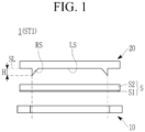
- FIG. 1 is a cross-sectional view taken along line I-I in FIG. 2 , and showing a state before notching which may be a first step while notching an electrode substrate by using a rechargeable battery electrode substrate notching device and a rechargeable battery electrode substrate notching method according to one or more embodiments of the present disclosure.
- a rechargeable battery electrode substrate notching device 1 according to one or more embodiments includes a die 10 and a punch 20.
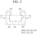
- FIG. 2 is a plan view of the punch used in the rechargeable battery electrode substrate notching device 1 of FIG. 1 according to one or more embodiments of the present disclosure
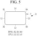
- FIG. 5 is a plan view of an electrode notched using the rechargeable battery electrode substrate notching device 1 and the rechargeable battery electrode substrate notching method according to one or more embodiments of the present disclosure.
- the punch 20 may be configured to notch an electrode substrate S into an electrode E having a straight part LP (L1, L2, L3, or L4) and a round part RP (R1, R2, R3, or R4) by being lifted toward the die 10 while the electrode substrate S may be installed on an upper surface of the die 10.
- a straight part LP L1, L2, L3, or L4
- a round part RP R1, R2, R3, or R4
- the electrode substrate S may include an electrode plate S1 and a composite layer S2 installed on at least one surface of the electrode plate S 1, in a thickness direction. Therefore, the notched electrode E may include the notched electrode plate S1 and the composite layer S2.
- FIG. 17 is a plan view of an electrode substrate continuously notched using a rechargeable battery electrode substrate notching device and a rechargeable battery electrode substrate notching method according to one or more embodiments of the present disclosure.
- the electrode substrate S may be released from a reel state and continuously supplied while having a tension between the die 10 and the punch 20.
- the electrode substrate S may include a coated part CP disposed in a length direction on its one side in a width direction and an uncoated part UCP disposed in the length direction on the other side in the width direction.
- the die 10 and the punch 20 may be configured to notch the electrode substrate S into the electrode E, and notch the uncoated part UCP into a tab part T of the electrode E.
- the punch 20 may be formed to correspond to a shape of the electrode E, which may be a notching target, and the electrode E may include the straight parts LP, that is, the first, second, third, and fourth straight lines L1, L2, L3, and L4 and the round parts RP, that is, the first, second, third, and fourth rounds R1, R2, R3, and R4.
- the punch 20 may include a round shear part RS, that is, a first, second, third, or fourth round shear knife RS1, RS2, RS3, or RS4 corresponding to the round part RP (R1, R2, R3, or R4).
- the punch 20 may further include a straight shear part LS, that is, a first, second, or third straight shear knife LS1, LS2, or LS3, corresponding to the straight part LP (L1, L2, L3, or L4).
- the straight shear parts LS that is, the first, second, and third straight shear knives LS1, LS2, and LS3 may improve a notching quality at each edge of the straight parts LP and reduce a foreign material occurring in a scrap if notching the straight parts LP of the electrode E, that is, the first, second, third, and fourth straight lines L1, L2, L3, and L4.
- the round shear parts RS that is, the first, second, third, and fourth round shear knives RS1, RS2, RS3, and RS4 may improve the notching quality at each edge of the round parts RP and reduce the foreign material occurring in the scrap if notching the round parts RP of the electrode E, that is, the first, second, third, and fourth rounds R1, R2, R3, and R4.
- the round shear parts RS (RS 1, RS2, RS3, and RS4) and the straight shear parts LS (LS1, LS2, and LS3) may suppress the foreign material occurring in a process of notching the electrode substrate S into the electrode E, thereby reducing a short circuit defect, an appearance defect, or a potential defect that causes a defect during use, in an entire process or in a rechargeable battery cell including the electrode E.
- the round shear part RS (RS1, RS2, RS3, or RS4) may be formed on (e.g. may form) at least one of the four round parts RP (R1, R2, R3, and R4) of the electrode E.
- the straight shear part LS (LS1, LS2, or LS3) may be formed on (e.g. may form) at least one of the four straight parts LP (L1, L2, L3, and L4) of the electrode E.
- the electrode E may include the four straight parts LP (L1, L2, L3, and L4) and the four round parts RP (R1, R2, R3, and R4).
- the round shear parts RS may be formed as the four round shear knives, i.e. the first, second, third, and fourth round shear knives RS1, RS2, RS3, and RS4 corresponding to the four round parts RP (R1, R2, R3, and R4).
- the straight shear parts LS may be formed as three straight shear knives, that is, the first, second, and third straight shear knives LS1, LS2, and LS3 corresponding to the three straight parts LP (L1, L2, and L3).
- the second straight shear knife LS2, one of the straight shear parts LS may notch the fourth straight part L4 of the straight parts LP of the electrode E in the next notching step during the continuous notching process, as shown in FIG. 17 , after notching the second straight line L2 of the straight parts LP of the electrode E.
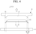
- FIG. 3 is a cross-sectional view showing a state during notching (or pressing) in a second step following the first step of FIG. 1 according to one or more embodiments; and FIG. 4 is a cross-sectional view showing a state after notching during the second step that follows FIG. 3 according to one or more embodiments.
- the round shear part RS (RS 1, RS2, RS3, or RS4) of the punch 20 may have a convex shear angle of a height H higher than the straight shear part LS (LS1, LS2, or LS3) having the same height as the reference height SL along the straight part LP (L1, L2, or L3).
- the rechargeable battery electrode substrate notching method may include: a first step ST1 (see FIG. 1 ) of installing the electrode substrate S on the die 10; and a second step ST2 (see FIGS. 3 and 4 ) of notching the electrode substrate S into the stack-type electrode E having the straight parts LP (L1, L2, and L3) and the round parts RP (R1, R2, R3, and R4) by lifting the punch 20 toward the die 10.
- the round part RP (R1, R2, R3, or R4) of the electrode E is notched using the round shear part RS (RS1, RS2, RS3, or RS4) of the punch 20.
- the straight part LP (L1, L2, or L3) of the electrode E may be further notched using the straight shear part LS (LS1, LS2, and LS3) of the punch 20.
- the straight shear part LS (LS1, LS2, or LS3) may have the same height as the reference height SL.
- the round part RP (R1, R2, R3, or R4) of the electrode E may be first notched using the round shear part RS (RS1, RS2, RS3, or RS4) of the punch 20 to have the convex shear angle of the height H higher than the straight shear part LS (LS1, LS2, or LS3).
- the composite layer S2 on the electrode plate S1 that corresponds to the convex shear angle may have a desorption part S21 where a desorption phenomenon occurs.
- the composite layer S2 may have an incline S25 formed by the convex shear angle of the round shear part RS (RS1, RS2, RS3, RS4) of the punch 20.
- the desorption part S21 may be formed on the electrode plate S1 by following the incline S25.
- the desorption part S21 of the composite layer S2 may be larger than zero ⁇ m and smaller than 300 ⁇ m (0 ⁇ S21 ⁇ 300 ⁇ m).
- the desorption part S21 in according to one or more embodiments may be smaller than a desorption part which may be larger than 300 ⁇ m that occurs when performing the notching by using a conventional punch without the round shear part RS (RS1, RS2, RS3, or RS4).
- the minimum desorption part S21 of the composite layer S2 may be the minimization desorption of the active material at the electrode E.
- the desorption part S21 may be smaller than a round R (R1, R2, R3, R4) of the round shear part RS (RS 1, RS2, RS3, RS4) may be larger, and the height H of the convex shear angle may be higher.
- the round R may be greater than zero, and less than 10 mm (0 ⁇ R ⁇ 10 mm) and the height H of the convex shear angle may be greater than zero and less than 1 mm (0 ⁇ H ⁇ 1 mm).
- the round R and the height H are described with reference to FIG. 4 by being denoted by the same reference numerals as those of the round shear part RS and the round part RP, their relationship may be the same as the relationship between the round shear part RS and the round part RP. That is, in the straight part LP (L1, L2, L3, or L4) of the electrode E, which may be notched using the straight shear part LS (LS1, LS2, or LS3), the composite layer S2 on the electrode plate S1 that corresponds to the convex shear angle may have the desorption part S21 where the desorption phenomenon occurs.
- the desorption part S21 of the composite layer S2 may be larger than zero ⁇ m and smaller than 300 ⁇ m (0 ⁇ S21 ⁇ 300 ⁇ m).
- the desorption part S21 in one or more embodiments may be smaller than a desorption part which may be larger than 300 ⁇ m that occurs when performing the notching by using a conventional punch without the straight shear part LS (LS1, LS2, or LS3).
- the minimum desorption part S21 of the composite layer S2 may be the minimization desorption of the active material at the electrode E.
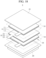
- FIG. 18 is an exploded perspective view of a rechargeable battery according to one or more embodiments of the present disclosure.
- a rechargeable battery B may include an electrode assembly 100 formed by stacking a positive electrode 101 and a negative electrode 102 while having a separator 103 disposed therebetween, and pouches 200 and 210 accommodating the electrode assembly 100.
- the electrode E may include the electrode plate S1 and the composite layer S2 disposed on at least one surface of the electrode plate S1, in the thickness direction.
- the electrodes 101 and 102 may respectively have the composite layers 112 and 122 on both surfaces of electrode plates 111 and 121, and tabs 113 and 123 on each one side of the electrode plates 111 and 121.
- the composite layer S2 on the electrode plate S1 may have the desorption part S21 where the desorption phenomenon occurs. That is, the composite layer S2 may have the incline S25.
- the desorption part S21 may be formed on the electrode plate S1 by following the incline S25.
- the desorption part S21 may be larger than zero ⁇ m and smaller than 300 ⁇ m (0 ⁇ S21 ⁇ 300 ⁇ m).
- the rechargeable battery B using the electrodes E (101 or 102) may prevent the capacity ratio N/P of the negative electrode and the positive electrode from being reversed and the capacity compared to the design from being reduced.
- the rechargeable battery B may minimize the desorbed active material, thus minimizing the foreign material occurring in the notched electrode E (101 or 102) or the electrode assembly 100 including the electrode E (101 or 102).
- the short circuit defect rate of the electrode assembly 100 may be lowered and minimize the defect in the voltage deviation value dV of the completed rechargeable battery B may be minimized, as well as the abnormal phenomenon in its lifespan.
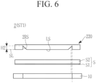
- FIG. 6 is a cross-sectional view showing a state before notching, which may be a first step while notching an electrode substrate by using a rechargeable battery electrode substrate notching device and a rechargeable battery electrode substrate notching method according to one or more embodiments of the present disclosure
- FIG. 7 is a cross-sectional view showing a state during notching (or pressing) in a second step following the first step of FIG. 6 according to one or more embodiments
- FIG. 8 is a cross-sectional view showing a state after notching during the second step that follows FIG. 7 according to one or more embodiments.
- a round shear part 2RS of a punch 220 may be formed (e.g. may form) along the straight part LP (L1, L2, or L3) (see FIG. 5 ) while having a concave shear angle lower than the straight shear part LS which may have the same height as the reference height SL.
- the straight part LP of the electrode E may be notched using the straight shear part LS of the punch 220.
- the straight shear part LS may have the same height as the reference height SL.
- the round part RP of the electrode E may be notched using the round shear part 2RS of the punch 220.
- the round part RP of the electrode E may be later notched using the round shear part 2RS of the punch 220 to have the concave shear angle of a depth H2 lower than the straight shear part LS.
- the composite layer S2 on the electrode plate S1 that corresponds to the concave shear angle may have a desorption part S22 where the desorption phenomenon occurs.
- the composite layer S2 may have an incline S26 formed by the concave shear angle of the round shear part 2RS of the punch 220.
- the desorption part S22 may be formed on the electrode plate S1 by overlapping the incline S26.
- the composite layer S2 on the electrode plate S1 may have the desorption part S22 where the desorption phenomenon occurs. That is, the composite layer S2 may have the incline S26.
- the desorption part S22 may be formed on the electrode plate S1 by overlapping the incline S26.
- the desorption part S22 may be larger than zero ⁇ m and smaller than 300 ⁇ m (0 ⁇ S22 ⁇ 300 ⁇ m).
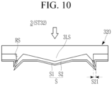
- a rechargeable battery electrode substrate notching device 3 may have a straight shear part 3LS having the convex shear angle, in addition to the notching device 1 of FIGS. 1-5 .
- the straight part LP of the electrode E may be notched using the straight shear part 3LS of the punch 320, and the round part RP of the electrode E may be notched simultaneously using the round shear part RS.
- Each of the straight shear part 3LS and round shear part RS may have the higher height H higher than the reference height SL.
- the straight part LP and round part RP of the electrode E may be notched simultaneously using the straight shear part 3LS and round shear part RS of the punch 320.
- the composite layer S2 on the electrode plate S1 that corresponds to the convex shear angle may have the desorption part S21 where the desorption phenomenon occurs.
- the composite layer S2 may have the incline S25 formed by the convex shear angle of the straight shear part 3LS and round shear part RS of the punch 320.
- the desorption part S21 may be formed on the electrode plate S1 by following the incline S25.
- the desorption part S21 of the composite layer S2 may be larger than zero ⁇ m and smaller than 300 ⁇ m (0 ⁇ S21 ⁇ 300 ⁇ m). In other embodiments, the desorption part S21 may be smaller than a desorption part which may be larger than 300 ⁇ m that occurs when performing the notching by using the conventional punch without the straight shear part 3LS or the round shear part RS.
- the minimum desorption part S21 of the composite layer S2 may be the minimization desorption of the active material at the electrode E.
- FIG. 12 is a cross-sectional view showing a state before notching, which may be a first step while notching an electrode substrate by using a rechargeable battery electrode substrate notching device and a rechargeable battery electrode substrate notching method according to one or more embodiments of the present disclosure
- FIG. 13 is a cross-sectional view showing a state during notching (or pressing) in a second step following the first step of FIG. 12 according to one or more embodiments
- FIG. 14 is a cross-sectional view showing a state after notching during the second step that follows FIG. 13 according to one or more embodiments.
- a rechargeable battery electrode substrate notching device 4 may have the straight shear part 3LS having the convex shear angle, in addition to the notching device 2 of FIGS. 6-8 .
- the straight part LP of the electrode E may be first notched using the straight shear part 3LS of the punch 420, and the round part RP of the electrode E may be later notched using the round shear part 2RS.
- the straight shear part 3LS may have the height H higher than the reference height SL
- the round shear part 2RS may have the depth H2 lower than the reference height SL.
- the composite layer S2 on the electrode plate S1 that corresponds to the concave shear angle may have the desorption part S22 where the desorption phenomenon occurs.
- the composite layer S2 may have the incline S25 formed by the convex shear angle of the straight shear part 3LS of the punch 420 (see FIG. 4 ).
- the incline in the cross-sectional view may be formed by cutting the convex shear angle of the straight shear part 3LS and may have the same structure as that of the incline S25 in the cross-sectional view acquiring by cutting the convex shear angle of the round shear part RS in FIG. 4 .
- the desorption part S21 may be formed on the electrode plate S1 by following the incline S25.
- the incline S26 may be formed by the concave shear angle of the round shear part 2RS.
- the desorption part S22 may be formed on the electrode plate S1 by overlapping the incline S26 (see FIGS. 8 and 14 ).
- the desorption part S21 or S22 of the composite layer S2 may be larger than zero ⁇ m and smaller than 300 ⁇ m (0 ⁇ S21 ⁇ 300 ⁇ m, 0 ⁇ S22 ⁇ 300 ⁇ m). In some embodiments, the desorption part S21 or S22 may be smaller than a desorption part which may be larger than 300 ⁇ m that occurs when performing the notching by using a conventional punch without the straight shear part 3LS or the round shear part 2RS.
- the minimum desorption part S21 or S22 of the composite layer S2 may be the minimization desorption of the active material at the electrode E.
- the composite layer S2 on the electrode plate S1 may have the desorption parts S21 and S22 where the desorption phenomenon occurs. That is, the composite layer S2 may have the inclines S25 and S26.
- the desorption part S21 may be formed on the electrode plate S1 by following the incline S25.
- the desorption part S22 may be formed on the electrode plate S1 by overlapping the incline S26.
- the desorption part S21 or S22 may be larger than zero ⁇ m and smaller than 300 ⁇ m (0 ⁇ S21 ⁇ 300 ⁇ m, 0 ⁇ S22 ⁇ 300 ⁇ m). However, this is merely one example and the size of the desorption part S21 or S22 may vary.
- FIG. 15 is a cross-sectional view of a punch used in a rechargeable battery electrode substrate notching device according to one or more embodiments of the present disclosure.
- a punch 520 of the rechargeable battery electrode substrate notching device may have a straight shear part 5LS having a concave shear angle, in addition to the punch 20 of the notching device 1 of FIGS. 1-5 .
- the straight shear part 5LS of the punch 520 may have the concave shear angle of the depth H2 lower than the reference height SL along the straight part LP (L1, L2, or L3).
- the round shear part RS of the punch 520 may have the convex shear angle of the height H higher than the reference height SL along the round part RP (R1, R2, R3, or R4).
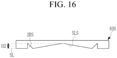
- FIG. 16 is a cross-sectional view of a punch used in a rechargeable battery electrode substrate notching device according to one or more embodiments of the present disclosure.
- a punch 620 of the rechargeable battery electrode substrate notching device may have the straight shear part 5LS having the concave shear angle, in addition to the punch 220 of the notching device 2 of FIGS. 6-8 .
- the straight shear part 5LS of the punch 620 may have the concave shear angle of the depth H2 lower than the reference height SL along the straight part LP (L1, L2, or L3).
- the round shear part 2RS of the punch 620 may have the concave shear angle of the height H2 lower than the reference height SL along the round part RP (R1, R2, R3, or R4).
- embodiments of the present disclosure may apply the shear angle, that is, the round shear part of the punch to the round region that corresponds to the round part of the electrode to thus minimize the desorption of the active material in the round part of the electrode, thereby preventing the capacity ratio N/P of the negative electrode and the positive electrode from being reversed and the capacity compared to the design from being reduced.
- Embodiments of the present disclosure may apply the shear angle, that is, the straight shear part of the punch to the straight region that corresponds to the straight part of the electrode to minimize the desorption of the active material in the straight part of the electrode, thereby preventing the capacity ratio N/P of the negative electrode and the positive electrode from being reversed and the capacity compared to the design from being reduced.
- Embodiments of the present disclosure may minimize the active material desorbed from at least one side of the round part or straight part of the electrode, thereby minimizing the foreign material in the notched electrode or electrode assembly. In this way, an embodiment may lower the short circuit defect rate of the electrode assembly and minimize the defect in the voltage deviation value dV of the completed rechargeable battery cell and the abnormal phenomenon in its lifespan.
Landscapes
- Engineering & Computer Science (AREA)
- Chemical & Material Sciences (AREA)
- Chemical Kinetics & Catalysis (AREA)
- Electrochemistry (AREA)
- General Chemical & Material Sciences (AREA)
- Manufacturing & Machinery (AREA)
- Mechanical Engineering (AREA)
- Life Sciences & Earth Sciences (AREA)
- Forests & Forestry (AREA)
- Secondary Cells (AREA)
- Connection Of Batteries Or Terminals (AREA)
- Battery Electrode And Active Subsutance (AREA)
Applications Claiming Priority (1)
| Application Number | Priority Date | Filing Date | Title |
|---|---|---|---|
| KR1020230091249A KR102902558B1 (ko) | 2023-07-13 | 2023-07-13 | 이차전지 전극기재 노칭장치, 그 노칭 방법 및 그에 의한 이차전지 |
Publications (1)
| Publication Number | Publication Date |
|---|---|
| EP4492484A1 true EP4492484A1 (de) | 2025-01-15 |
Family
ID=91924422
Family Applications (1)
| Application Number | Title | Priority Date | Filing Date |
|---|---|---|---|
| EP24188134.1A Pending EP4492484A1 (de) | 2023-07-13 | 2024-07-11 | Vorrichtung zur kerbung eines elektrodensubstrats einer wiederaufladbaren batterie, kerbungsverfahren und wiederaufladbare batterie damit |
Country Status (3)
| Country | Link |
|---|---|
| US (1) | US20250018592A1 (de) |
| EP (1) | EP4492484A1 (de) |
| KR (1) | KR102902558B1 (de) |
Citations (4)
| Publication number | Priority date | Publication date | Assignee | Title |
|---|---|---|---|---|
| CN104852014A (zh) * | 2015-05-14 | 2015-08-19 | 宁德时代新能源科技有限公司 | 一种制备锂离子电池极片元件的装置 |
| US20170062867A1 (en) * | 2015-08-27 | 2017-03-02 | Samsung Sdi Co., Ltd. | Electrode assembly, manufacturing method thereof, and rechargeable battery |
| KR101714110B1 (ko) * | 2013-10-31 | 2017-03-08 | 주식회사 엘지화학 | 이차 전지의 전극 노칭장치 및 이에 의해 제작된 전극용 필름 |
| KR101737790B1 (ko) * | 2016-07-15 | 2017-05-19 | 안혁 | 하이브리드 자동차용 전지 극판을 동시에 복수 개 가공하는 프레스 금형장치 |
Family Cites Families (1)
| Publication number | Priority date | Publication date | Assignee | Title |
|---|---|---|---|---|
| WO2022176492A1 (ja) * | 2021-02-17 | 2022-08-25 | 株式会社村田製作所 | 電池用電極およびその製造方法、ならびに電池 |
-
2023
- 2023-07-13 KR KR1020230091249A patent/KR102902558B1/ko active Active
-
2024
- 2024-04-15 US US18/635,371 patent/US20250018592A1/en active Pending
- 2024-07-11 EP EP24188134.1A patent/EP4492484A1/de active Pending
Patent Citations (4)
| Publication number | Priority date | Publication date | Assignee | Title |
|---|---|---|---|---|
| KR101714110B1 (ko) * | 2013-10-31 | 2017-03-08 | 주식회사 엘지화학 | 이차 전지의 전극 노칭장치 및 이에 의해 제작된 전극용 필름 |
| CN104852014A (zh) * | 2015-05-14 | 2015-08-19 | 宁德时代新能源科技有限公司 | 一种制备锂离子电池极片元件的装置 |
| US20170062867A1 (en) * | 2015-08-27 | 2017-03-02 | Samsung Sdi Co., Ltd. | Electrode assembly, manufacturing method thereof, and rechargeable battery |
| KR101737790B1 (ko) * | 2016-07-15 | 2017-05-19 | 안혁 | 하이브리드 자동차용 전지 극판을 동시에 복수 개 가공하는 프레스 금형장치 |
Also Published As
| Publication number | Publication date |
|---|---|
| KR20250010962A (ko) | 2025-01-21 |
| US20250018592A1 (en) | 2025-01-16 |
| KR102902558B1 (ko) | 2025-12-18 |
Similar Documents
| Publication | Publication Date | Title |
|---|---|---|
| US10923758B2 (en) | Electrode assembly having step, secondary battery, battery pack and device including electrode assembly, and method of manufacturing electrode assembly | |
| US9685679B2 (en) | Stepwise electrode assembly having variously-shaped corner and secondary battery, battery pack and device comprising the same | |
| KR101379958B1 (ko) | 전극 조립체, 전지셀, 전극 조립체의 제조방법 및 전지셀의 제조 방법 | |
| KR101553542B1 (ko) | 2차 전지 내부 셀 스택 방법 및 이를 이용하여 제조되는 셀 스택 | |
| KR101575984B1 (ko) | 전극탭 접합성이 우수한 전극 조립체, 이를 포함하는 전지셀, 디바이스 및 이의 제조방법 | |
| US10559808B2 (en) | Lithium secondary battery having improved safety by using bimetal tab | |
| KR102693188B1 (ko) | 이차 전지 | |
| EP3975306A1 (de) | Sekundärbatterie | |
| EP4492484A1 (de) | Vorrichtung zur kerbung eines elektrodensubstrats einer wiederaufladbaren batterie, kerbungsverfahren und wiederaufladbare batterie damit | |
| US20250006945A1 (en) | Electrode, electrode assembly and rechargeable battery including the same | |
| KR101450951B1 (ko) | 안전성이 향상된 이차전지용 전극리드 및 이를 이용한 이차전지 | |
| EP4593186A1 (de) | Elektrodenanordnung für wiederaufladbare batterie | |
| EP4593187A1 (de) | Elektrodenanordnung für wiederaufladbare batterie | |
| US20250266484A1 (en) | Electrode assembly taping device and method of rechargeable battery | |
| EP4556419A1 (de) | Klebebandvorrichtung für sekundärbatterie und damit hergestellte sekundärbatterie | |
| KR20200102167A (ko) | 전극조립체 | |
| US20250062389A1 (en) | Rechargeable battery | |
| EP4708419A1 (de) | Vorrichtung zur herstellung einer sekundärbatterie und verfahren zur herstellung einer sekundärbatterie | |
| EP4685983A1 (de) | Sekundärbatterie und verfahren zur herstellung davon | |
| KR102954989B1 (ko) | 이차전지 | |
| KR20250177768A (ko) | 테이프가 부착된 이차 전지 전극 및 이차 전지 전극을 포함한 전극 조립체 | |
| CN110676501B (zh) | 高压电池单元 | |
| KR20260039402A (ko) | 용접 장치 및 이를 이용한 전극 제조 방법 | |
| JP2026507366A (ja) | 二次電池用端面電極、その製造方法、およびそれを含む電極アセンブリおよび二次電池 | |
| EP3979356A1 (de) | Sekundärbatterie |
Legal Events
| Date | Code | Title | Description |
|---|---|---|---|
| PUAI | Public reference made under article 153(3) epc to a published international application that has entered the european phase |
Free format text: ORIGINAL CODE: 0009012 |
|
| STAA | Information on the status of an ep patent application or granted ep patent |
Free format text: STATUS: REQUEST FOR EXAMINATION WAS MADE |
|
| 17P | Request for examination filed |
Effective date: 20240711 |
|
| AK | Designated contracting states |
Kind code of ref document: A1 Designated state(s): AL AT BE BG CH CY CZ DE DK EE ES FI FR GB GR HR HU IE IS IT LI LT LU LV MC ME MK MT NL NO PL PT RO RS SE SI SK SM TR |