EP4491994A1 - Ignition device - Google Patents
Ignition device Download PDFInfo
- Publication number
- EP4491994A1 EP4491994A1 EP23766865.2A EP23766865A EP4491994A1 EP 4491994 A1 EP4491994 A1 EP 4491994A1 EP 23766865 A EP23766865 A EP 23766865A EP 4491994 A1 EP4491994 A1 EP 4491994A1
- Authority
- EP
- European Patent Office
- Prior art keywords
- igniter
- press
- tube body
- ignition device
- fitting
- Prior art date
- Legal status (The legal status is an assumption and is not a legal conclusion. Google has not performed a legal analysis and makes no representation as to the accuracy of the status listed.)
- Pending
Links
Images

Classifications
-
- F—MECHANICAL ENGINEERING; LIGHTING; HEATING; WEAPONS; BLASTING
- F42—AMMUNITION; BLASTING
- F42B—EXPLOSIVE CHARGES, e.g. FOR BLASTING, FIREWORKS, AMMUNITION
- F42B3/00—Blasting cartridges, i.e. case and explosive
- F42B3/10—Initiators therefor
- F42B3/12—Bridge initiators
-
- F—MECHANICAL ENGINEERING; LIGHTING; HEATING; WEAPONS; BLASTING
- F42—AMMUNITION; BLASTING
- F42B—EXPLOSIVE CHARGES, e.g. FOR BLASTING, FIREWORKS, AMMUNITION
- F42B3/00—Blasting cartridges, i.e. case and explosive
- F42B3/10—Initiators therefor
- F42B3/12—Bridge initiators
- F42B3/125—Bridge initiators characterised by the configuration of the bridge initiator case
-
- F—MECHANICAL ENGINEERING; LIGHTING; HEATING; WEAPONS; BLASTING
- F42—AMMUNITION; BLASTING
- F42B—EXPLOSIVE CHARGES, e.g. FOR BLASTING, FIREWORKS, AMMUNITION
- F42B3/00—Blasting cartridges, i.e. case and explosive
- F42B3/04—Blasting cartridges, i.e. case and explosive for producing gas under pressure
-
- H—ELECTRICITY
- H01—ELECTRIC ELEMENTS
- H01H—ELECTRIC SWITCHES; RELAYS; SELECTORS; EMERGENCY PROTECTIVE DEVICES
- H01H3/00—Mechanisms for operating contacts
- H01H3/32—Driving mechanisms, i.e. for transmitting driving force to the contacts
Definitions
- the present invention relates to an ignition device used for a safety device such as an automobile.
- the seat belt device is provided for the purpose of preventing the occupant from being released into a vehicle or the outside of the vehicle due to an impact generated at the time of collision of the vehicle or the like, and binds and fixes the occupant to the seat by winding the belt around the body of the occupant.
- a seat belt device having a pretensioner function has been widely used in order to improve an occupant protection function.
- the pretensioner function instantaneously winds up the slack of the seat belt caused by a thickness of the clothing or the like at the time of collision or immediately before collision, and enhances the effect of restraining the occupant.
- This pretensioner function is realized by strongly drawing a seat belt by a pressure of a gas output from a gas generator called a micro gas generator (MGG).
- MMGG micro gas generator
- the ignition device of the gas generator of Patent Literature 1 includes an igniter that is disposed inside a cup body and ignites a gas generating agent by energization, and a holder that seals the gas generating agent in the cup body.
- the holder is formed of resin and is formed integrally with the igniter by insert molding.
- Patent Literature 1 JP 2002-239371 A
- the ignition device in Patent Literature 1 exhibits a sufficient function by being used in a seat belt device having a pretensioner function, but such a function may be excessive in light of the purpose or application.
- the ignition device in Patent Literature 1 is simply used as an ignition device for a current breaker, the original capability is excessive, and a part of the manufacturing cost may be wasted.
- an object of the present invention is to provide an ignition device capable of securing a necessary function according to a purpose or an application and capable of easily performing assembly by reducing the number of parts as compared with the related art.
- a surface (hereinafter, an opposite surface) of the header on a side opposite to a side on which the ignition charge is disposed is in contact with a surface that is radially inner than the annular groove and is formed on an inner wall of the bore so as to face the opposite surface.
- a tapered shape that reduces in diameter in a direction of the press-fitting is formed halfway from the surface that is radially inner than the annular groove and is formed on the inner wall of the bore so as to face the opposite surface to a portion of the bore where the pair of terminal pins is inserted on a side opposite to a side where the tube body is press-fitted.
- an annular weak portion is formed on an outer peripheral portion of the insertion port.
- a tapered shape that reduces in diameter along a direction of the press-fitting is formed between the insertion port and the press-fitting portion of the bore.
- a pair of through holes into which each of the pair of terminal pins is inserted is formed in a portion of the bore into which the pair of terminal pins is inserted on a side opposite to a side where the tube body is press-fitted.
- This ignition device can be used as a current breaker, for example, for burning a conductive wire through which current flows or for moving a piston to cut the conductive wire.
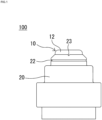
- an ignition device 100 of the present embodiment includes an igniter 10 that accommodates an ignition charge 11 to be ignited by energization, and a holder 20 that includes an insertion port 21a for inserting the igniter 10 and is integrated with the igniter 10 by fitting the igniter 10 from the insertion port 21a.
- the igniter 10 includes a tube body 12 that loads the ignition charge 11, a metal header 13 that seals the ignition charge 11 in the bottomed cylindrical tube body 12 including an opening, a pair of terminal pins 14 protruding from the header 13, an insulator 15 such as glass that insulates between the terminal pins 14, and an bridge wire 16 connected between the terminal pins 14 on the insulator 15 in the tube body 12 and in contact with the ignition charge 11.
- An end portion 12a of the tube body 12 is formed so as to protrude with respect to the header 13.
- the header 13 includes a surface 13a formed on a side opposite to a side of the ignition charge 11.
- the bridge wire 16 when the bridge wire 16 is energized via the pair of terminal pins 14, the bridge wire 16 generates Joule heat, the ignition charge 11 is instantly ignited by the heat, and a bottom portion of the tube body 12 is broken by the increase in pressure in the tube body 12 and the header 13.
- a conductive wire or the like can be burned off by the flame and the pressure wave of the ejected ignition charge 11, or a drive source for driving a moving body such as a piston can be used.
- the igniter 10 is fixed to the holder 20 in a state where the pair of terminal pins 14 is inserted into the bore 21 formed in a substantially central portion of the holder 20 and in a state where a central axis of the igniter 10 itself and a central axis of the holder 20 substantially coincide with each other.
- a cylindrical portion 12b of the tube body 12 is press-fitted and fixed to a press-fitting portion 21c formed in the bore 21 of the holder 20, whereby the igniter 10 is fixed to the holder 20.
- the end portion 12a of the tube body 12 is fitted into an annular groove 21d to be described later formed in the bore 21, and a labyrinth structure is formed by at least an inner wall portion, an end surface portion, and an outer wall portion of the end portion 12a and the annular groove 21d.
- this labyrinth structure may also include a portion constituted by an outer wall of the tube body 12, an inner wall of the press-fitting portion 21c, the surface 13a, a seating surface 21e to be described later, a second tapered portion 21f to be described later, and a pair of through holes 21g to be described later.
- the holder 20 is a substantially tubular member in which the bore 21 into which the igniter 10 is inserted and press-fitted and fixed is formed in a central portion.
- the bore 21 includes the insertion port 21a, a first tapered portion 21b, the press-fitting portion 21c, the annular groove 21d, the seating surface 21e, the second tapered portion 21f, the through hole 21g, and a female connector portion 21h.
- the holder 20 is formed as a single body by, for example, injection molding using a flowable resin material.
- the insertion port 21a has an inner diameter larger than an outer diameter of the tube body 12, and serves as a guide portion when the igniter 10 is inserted. Furthermore, an annular weak portion 22 is formed in an outer peripheral portion of the holder 20 facing the insertion port 21a, and a notch portion 23 is formed in an upper end portion of the insertion port 21a.
- the weak portion 22 protects the press-fitting portion 21c by serving as a starting point of breakage in a case where a protrusion including the first tapered portion 21b and the press-fitting portion 21c of the holder 20 receives combustion pressure generated by the activation of the igniter 10 in an outward direction via the tube body 12, and prevents the press-fitting and fixing of the tube body 12 to the press-fitting portion 21c from being released.
- the first tapered portion 21b is formed between the insertion port 21a and the press-fitting portion 21c, has a tapered shape that reduces in diameter along a press-fitting direction of the tube body 12, and guides the tube body 12 to the press-fitting portion 21c. That is, the insertability (assemblability) of the igniter 10 is improved as compared with the case where the first tapered portion 21b is not formed.
- the press-fitting portion 21c is a portion that can hold the igniter 10 and improve airtightness (sealability) inside the igniter 10 by press-fitting and fixing the tube body 12.
- the annular groove 21d is provided continuously from the press-fitting portion 21c, is a portion fitted into the end portion 12a of the tube body 12, and forms a labyrinth structure together with the inner wall portion, the end surface portion, and the outer wall portion of the end portion 12a.
- This labyrinth structure it is possible not only to maintain the combustion pressure generated by the igniter 10 together with the press-fitting portion 21c (to prevent leakage of gas generated at the time of activation of the igniter 10), but also to withstand mechanical vibration in the case of being mounted on a vehicle and impact at the time of activation.
- a groove depth of the annular groove 21d is deeper than a projection margin of the end portion 12a of the tube body 12, and the igniter 10 is seated on (in contact with) the seating surface 21e via the surface 13a of the header 13 on a side opposite to a side on which the ignition charge 11 is disposed.
- the high-pressure igniter 10 can be further used.
- the seating surface 21e is formed on an inner wall of the bore 21 so as to face the surface 13a on a radially inner side of the annular groove 21d, and is a surface on which the surface 13a of the header 13 of the igniter 10 is seated (in contact).
- the second tapered portion 21f is formed between the seating surface 21e and the pair of through holes 21g, and has a tapered shape that reduces in diameter along the press-fitting direction of the tube body 12.
- the second tapered portion 21f has a guide function similar to that of the first tapered portion 21b, and has better insertability (assemblability) of the igniter 10 (particularly, the pair of terminal pins 14) than a case where the second tapered portion 21f is not formed.
- the pair of through holes 21g can improve airtightness by regulating a clearance (gap) between the pair of terminal pins 14 and the holder 20, and can restrict positioning and movement of the igniter 10 in a circumferential direction.
- the female connector portion 21h is a portion formed to hold the pair of terminal pins 14 in a partially exposed state and to connect a male connector (not illustrated) of a harness for electrically connecting the pair of terminal pins 14 to, for example, a control unit (not illustrated).
- one notch portion 23 is formed to serve as a starting point of the damaged portion, and the shape of the damaged state (scattered object) can be stabilized. Note that it is possible to reduce scattered objects by changing the shape and arrangement positions of the weak portion 22 and the notch portion 23 or providing a plurality of the weak portions 22 and the notch portions 23 as necessary.
- an object for example, a conductive wire
- a pressure wave generated by the activation of the igniter 10 can be used as a driving force for moving a moving body such as a piston.
- the ignition device 100 can be used as a drive source of a current breaker having a configuration in which a cutter is attached to a tip of a piston, and a conductive wire or the like is cut off after the movement of the piston.
- the ignition device 100 capable of securing a necessary function according to a purpose or application.
- the ignition device 100 that can be easily assembled by reducing the number of parts as compared with the related art according to a purpose or application.
- an insulating cover is not necessary if the igniter 10 and a mating part to which the ignition device 100 is attached are not metal parts and are not contactable.
- the insulating cover is unnecessary in the case of use for a current breaker, a structure in which a space is provided between the igniter 10 and a piston moved by a pressure wave generated by the igniter 10, or in the case where the piston is made of resin.
- MMGG micro gas generator
- an insulating cover is required for a tube body or the like of an igniter that comes into contact with low explosive.
- the holder 20 is made of resin, the material cost can be reduced and the weight can be reduced as compared with the case where the holder 20 is made of metal. Furthermore, since the holder 20 is formed by injection molding alone, a mold structure is simple as compared with a unit integrally molded with the igniter 10, and insert molding as in the related art is unnecessary, so that the molding cycle time can be shortened and the manufacturing cost can be reduced. Furthermore, since the holder 20 is made of resin, the degree of freedom in shape is high as compared with the case of metal, and it is possible to easily change the shape, attach another component, and the like as necessary. Furthermore, since the holder 20 is made of resin, there is no possibility of insulation failure due to metal burrs (caulking and cutting residue) as in the case of metal.
- the process load can be reduced as compared with the related art.
- the assembling process is assembly by press-fitting, but since the assembling process is abutting against the seating surface 21e and does not include a caulking process or the like, fine process management is unnecessary, manufacturing is easy, and compactness of equipment is possible.
- the groove depth of the annular groove 21d is deeper than the projection margin of the end portion 12a of the tube body 12, and the igniter 10 is seated on the seating surface 21e via the surface 13a of the header 13.
- the assembly accuracy of the igniter 10 and the variation in the dimension of the end portion 12a are absorbed, so that the dimensional accuracy after assembly of the ignition device 100 is improved, and the influence due to a product type difference is minimized by sharing the holder 20 (It is possible to provide a variation of the ignition device by changing the igniter 10 to another type of igniter.), so that the cost reduction effect can be obtained. For example, it is possible to obtain a reduction in unit price of a component due to mass production of one component of the holder 20, a cost reduction effect due to simplification of assembly equipment, and an assembly cost reduction effect due to no stage change.
- a projection margin of the terminal pins 14 from the holder 20 is regulated by the standard of a connector fitted into the female connector portion 21h.
- the standard of the connector can be easily satisfied by seating the igniter 10 on the seating surface 21e via the surface 13a of the header 13, and since the surface 13a is pressed against the seating surface 21e in assembly, it is not necessary to control fine positional accuracy, and it is possible to provide relatively high positional accuracy although it is simple.
- the weak portion 22 can protect the press-fitting portion 21c and the above-described labyrinth structure from the combustion pressure generated in the igniter 10.
- the notch portion 23 becomes a starting point of the damaged portion, and the shape of the damaged state (scattered object) can be stabilized.
Landscapes
- Engineering & Computer Science (AREA)
- General Engineering & Computer Science (AREA)
- Air Bags (AREA)
- Automotive Seat Belt Assembly (AREA)
- Ignition Installations For Internal Combustion Engines (AREA)
Abstract
Description
- The present invention relates to an ignition device used for a safety device such as an automobile.
- Conventionally, seat belt devices and airbag devices have been widely used from the viewpoint of protecting an occupant of an automobile and the like. Among them, the seat belt device is provided for the purpose of preventing the occupant from being released into a vehicle or the outside of the vehicle due to an impact generated at the time of collision of the vehicle or the like, and binds and fixes the occupant to the seat by winding the belt around the body of the occupant.
- In recent years, a seat belt device having a pretensioner function has been widely used in order to improve an occupant protection function. The pretensioner function instantaneously winds up the slack of the seat belt caused by a thickness of the clothing or the like at the time of collision or immediately before collision, and enhances the effect of restraining the occupant. This pretensioner function is realized by strongly drawing a seat belt by a pressure of a gas output from a gas generator called a micro gas generator (MGG).
- As an ignition device used in such a gas generator, there is an ignition device described in Patent Literature 1 below. The ignition device of the gas generator of Patent Literature 1 includes an igniter that is disposed inside a cup body and ignites a gas generating agent by energization, and a holder that seals the gas generating agent in the cup body. The holder is formed of resin and is formed integrally with the igniter by insert molding.
- Patent Literature 1:
JP 2002-239371 A - Note that the ignition device in Patent Literature 1 exhibits a sufficient function by being used in a seat belt device having a pretensioner function, but such a function may be excessive in light of the purpose or application. For example, in a case where the ignition device in Patent Literature 1 is simply used as an ignition device for a current breaker, the original capability is excessive, and a part of the manufacturing cost may be wasted.
- Therefore, an object of the present invention is to provide an ignition device capable of securing a necessary function according to a purpose or an application and capable of easily performing assembly by reducing the number of parts as compared with the related art.
-
- (1) An ignition device according to the present invention is an ignition device including: an igniter that accommodates an ignition charge to be ignited by energization; and a holder that is integrated with the igniter by fitting the igniter into the holder, in which the igniter includes: a tube body containing the ignition charge inside and including an opening; an header that occludes the opening and seals the ignition charge inside the tube body; and a pair of terminal pins provided on the header, an end portion of the tube body forming the opening is formed so as to protrude with respect to the header, the holder includes: a bore including an insertion port that is formed inside and into which the igniter is inserted and a press-fitting portion into which the tube body is press-fitted via the insertion port, the igniter being fitted into and fixed to the bore by press-fitting the tube body into the press-fitting portion via the insertion port; and
- an annular groove that is formed in a part of an inner wall of the bore and into which an end portion of the tube body is fitted, and
- a labyrinth structure is formed by at least the end portion of the tube body fitted into the annular groove and the annular groove.
- In the ignition device of (1) described above, it is preferable that a surface (hereinafter, an opposite surface) of the header on a side opposite to a side on which the ignition charge is disposed is in contact with a surface that is radially inner than the annular groove and is formed on an inner wall of the bore so as to face the opposite surface.
- (3) In the ignition device of (2) described above, it is preferable that a tapered shape that reduces in diameter in a direction of the press-fitting is formed halfway from the surface that is radially inner than the annular groove and is formed on the inner wall of the bore so as to face the opposite surface to a portion of the bore where the pair of terminal pins is inserted on a side opposite to a side where the tube body is press-fitted.
- (4) In the ignition device of (1) to (3) described above, it is preferable that an annular weak portion is formed on an outer peripheral portion of the insertion port.
- (5) In the ignition device of (1) to (4) described above, it is preferable that a tapered shape that reduces in diameter along a direction of the press-fitting is formed between the insertion port and the press-fitting portion of the bore.
- (6) In the ignition device of (1) to (5) described above, it is preferable that a pair of through holes into which each of the pair of terminal pins is inserted is formed in a portion of the bore into which the pair of terminal pins is inserted on a side opposite to a side where the tube body is press-fitted.
- According to the configurations (1) to (6) described above, it is possible to provide an ignition device capable of securing a necessary function according to a purpose or an application and capable of easily performing assembly by reducing the number of parts as compared with the related art.
-
-
FIG. 1 is a side view illustrating an ignition device according to a first embodiment of the present invention. -
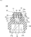
FIG. 2 is a cross-sectional view of the ignition device ofFIG. 1 . -
FIG. 3 is a partially enlarged view of the ignition device ofFIG. 2 . - Hereinafter, an ignition device according to an embodiment of the present invention will be described with reference to the drawings. This ignition device can be used as a current breaker, for example, for burning a conductive wire through which current flows or for moving a piston to cut the conductive wire.
- As illustrated in
FIGS. 1 to 3 , anignition device 100 of the present embodiment includes anigniter 10 that accommodates anignition charge 11 to be ignited by energization, and aholder 20 that includes aninsertion port 21a for inserting theigniter 10 and is integrated with theigniter 10 by fitting theigniter 10 from theinsertion port 21a. - The
igniter 10 includes atube body 12 that loads theignition charge 11, ametal header 13 that seals theignition charge 11 in the bottomedcylindrical tube body 12 including an opening, a pair ofterminal pins 14 protruding from theheader 13, aninsulator 15 such as glass that insulates between theterminal pins 14, and anbridge wire 16 connected between theterminal pins 14 on theinsulator 15 in thetube body 12 and in contact with theignition charge 11. Anend portion 12a of thetube body 12 is formed so as to protrude with respect to theheader 13. Theheader 13 includes asurface 13a formed on a side opposite to a side of theignition charge 11. - Note that, in the
igniter 10, when thebridge wire 16 is energized via the pair ofterminal pins 14, thebridge wire 16 generates Joule heat, theignition charge 11 is instantly ignited by the heat, and a bottom portion of thetube body 12 is broken by the increase in pressure in thetube body 12 and theheader 13. At this time, for example, a conductive wire or the like can be burned off by the flame and the pressure wave of the ejectedignition charge 11, or a drive source for driving a moving body such as a piston can be used. - Furthermore, the
igniter 10 is fixed to theholder 20 in a state where the pair ofterminal pins 14 is inserted into thebore 21 formed in a substantially central portion of theholder 20 and in a state where a central axis of theigniter 10 itself and a central axis of theholder 20 substantially coincide with each other. Specifically, acylindrical portion 12b of thetube body 12 is press-fitted and fixed to a press-fittingportion 21c formed in thebore 21 of theholder 20, whereby theigniter 10 is fixed to theholder 20. Furthermore, theend portion 12a of thetube body 12 is fitted into anannular groove 21d to be described later formed in thebore 21, and a labyrinth structure is formed by at least an inner wall portion, an end surface portion, and an outer wall portion of theend portion 12a and theannular groove 21d. Note that this labyrinth structure may also include a portion constituted by an outer wall of thetube body 12, an inner wall of the press-fittingportion 21c, thesurface 13a, aseating surface 21e to be described later, a second taperedportion 21f to be described later, and a pair of throughholes 21g to be described later. - The
holder 20 is a substantially tubular member in which thebore 21 into which theigniter 10 is inserted and press-fitted and fixed is formed in a central portion. Thebore 21 includes theinsertion port 21a, a firsttapered portion 21b, the press-fittingportion 21c, theannular groove 21d, theseating surface 21e, the secondtapered portion 21f, the throughhole 21g, and afemale connector portion 21h. Note that theholder 20 is formed as a single body by, for example, injection molding using a flowable resin material. - The
insertion port 21a has an inner diameter larger than an outer diameter of thetube body 12, and serves as a guide portion when theigniter 10 is inserted. Furthermore, an annularweak portion 22 is formed in an outer peripheral portion of theholder 20 facing theinsertion port 21a, and anotch portion 23 is formed in an upper end portion of theinsertion port 21a. Theweak portion 22 protects the press-fittingportion 21c by serving as a starting point of breakage in a case where a protrusion including the first taperedportion 21b and the press-fittingportion 21c of theholder 20 receives combustion pressure generated by the activation of theigniter 10 in an outward direction via thetube body 12, and prevents the press-fitting and fixing of thetube body 12 to the press-fittingportion 21c from being released. - The first
tapered portion 21b is formed between theinsertion port 21a and the press-fittingportion 21c, has a tapered shape that reduces in diameter along a press-fitting direction of thetube body 12, and guides thetube body 12 to the press-fittingportion 21c. That is, the insertability (assemblability) of theigniter 10 is improved as compared with the case where the firsttapered portion 21b is not formed. - The press-fitting
portion 21c is a portion that can hold theigniter 10 and improve airtightness (sealability) inside theigniter 10 by press-fitting and fixing thetube body 12. - The
annular groove 21d is provided continuously from the press-fittingportion 21c, is a portion fitted into theend portion 12a of thetube body 12, and forms a labyrinth structure together with the inner wall portion, the end surface portion, and the outer wall portion of theend portion 12a. With this labyrinth structure, it is possible not only to maintain the combustion pressure generated by theigniter 10 together with the press-fittingportion 21c (to prevent leakage of gas generated at the time of activation of the igniter 10), but also to withstand mechanical vibration in the case of being mounted on a vehicle and impact at the time of activation. Note that a groove depth of theannular groove 21d is deeper than a projection margin of theend portion 12a of thetube body 12, and theigniter 10 is seated on (in contact with) theseating surface 21e via thesurface 13a of theheader 13 on a side opposite to a side on which theignition charge 11 is disposed. Here, since airtightness (sealability) can be improved by fitting theend portion 12a after an adhesive or a sealant is applied to theannular groove 21d, the high-pressure igniter 10 can be further used. - The
seating surface 21e is formed on an inner wall of thebore 21 so as to face thesurface 13a on a radially inner side of theannular groove 21d, and is a surface on which thesurface 13a of theheader 13 of theigniter 10 is seated (in contact). - The second
tapered portion 21f is formed between theseating surface 21e and the pair of throughholes 21g, and has a tapered shape that reduces in diameter along the press-fitting direction of thetube body 12. The secondtapered portion 21f has a guide function similar to that of the firsttapered portion 21b, and has better insertability (assemblability) of the igniter 10 (particularly, the pair of terminal pins 14) than a case where the secondtapered portion 21f is not formed. - The pair of through
holes 21g can improve airtightness by regulating a clearance (gap) between the pair ofterminal pins 14 and theholder 20, and can restrict positioning and movement of theigniter 10 in a circumferential direction. - The
female connector portion 21h is a portion formed to hold the pair ofterminal pins 14 in a partially exposed state and to connect a male connector (not illustrated) of a harness for electrically connecting the pair ofterminal pins 14 to, for example, a control unit (not illustrated). - In a case where the
weak portion 22 is damaged at the time of activation, onenotch portion 23 is formed to serve as a starting point of the damaged portion, and the shape of the damaged state (scattered object) can be stabilized. Note that it is possible to reduce scattered objects by changing the shape and arrangement positions of theweak portion 22 and thenotch portion 23 or providing a plurality of theweak portions 22 and thenotch portions 23 as necessary. - In the
ignition device 100 configured as described above, an object (for example, a conductive wire) can be broken or melted by the flame generated by the activation of theigniter 10. Furthermore, a pressure wave generated by the activation of theigniter 10 can be used as a driving force for moving a moving body such as a piston. At this time, theignition device 100 can be used as a drive source of a current breaker having a configuration in which a cutter is attached to a tip of a piston, and a conductive wire or the like is cut off after the movement of the piston. - As described above, according to the present embodiment, it is possible to provide the
ignition device 100 capable of securing a necessary function according to a purpose or application. - Furthermore, according to the present embodiment, it is possible to provide the
ignition device 100 that can be easily assembled by reducing the number of parts as compared with the related art according to a purpose or application. For example, an insulating cover is not necessary if theigniter 10 and a mating part to which theignition device 100 is attached are not metal parts and are not contactable. In particular, in the case of use for a current breaker, a structure in which a space is provided between theigniter 10 and a piston moved by a pressure wave generated by theigniter 10, or in the case where the piston is made of resin, the insulating cover is unnecessary. However, in a case where the ignition device is incorporated in a micro gas generator (MGG), an insulating cover is required for a tube body or the like of an igniter that comes into contact with low explosive. - Furthermore, according to the present embodiment, since the
holder 20 is made of resin, the material cost can be reduced and the weight can be reduced as compared with the case where theholder 20 is made of metal. Furthermore, since theholder 20 is formed by injection molding alone, a mold structure is simple as compared with a unit integrally molded with theigniter 10, and insert molding as in the related art is unnecessary, so that the molding cycle time can be shortened and the manufacturing cost can be reduced. Furthermore, since theholder 20 is made of resin, the degree of freedom in shape is high as compared with the case of metal, and it is possible to easily change the shape, attach another component, and the like as necessary. Furthermore, since theholder 20 is made of resin, there is no possibility of insulation failure due to metal burrs (caulking and cutting residue) as in the case of metal. - Furthermore, according to the present embodiment, since an assembling process is only for assembling the
igniter 10 to theholder 20, the process load can be reduced as compared with the related art. Furthermore, according to the present embodiment, the assembling process is assembly by press-fitting, but since the assembling process is abutting against theseating surface 21e and does not include a caulking process or the like, fine process management is unnecessary, manufacturing is easy, and compactness of equipment is possible. - Furthermore, the groove depth of the
annular groove 21d is deeper than the projection margin of theend portion 12a of thetube body 12, and theigniter 10 is seated on theseating surface 21e via thesurface 13a of theheader 13. As a result, the assembly accuracy of theigniter 10 and the variation in the dimension of theend portion 12a are absorbed, so that the dimensional accuracy after assembly of theignition device 100 is improved, and the influence due to a product type difference is minimized by sharing the holder 20 (It is possible to provide a variation of the ignition device by changing theigniter 10 to another type of igniter.), so that the cost reduction effect can be obtained. For example, it is possible to obtain a reduction in unit price of a component due to mass production of one component of theholder 20, a cost reduction effect due to simplification of assembly equipment, and an assembly cost reduction effect due to no stage change. - Note that a projection margin of the terminal pins 14 from the
holder 20 is regulated by the standard of a connector fitted into thefemale connector portion 21h. According to the present embodiment, the standard of the connector can be easily satisfied by seating theigniter 10 on theseating surface 21e via thesurface 13a of theheader 13, and since thesurface 13a is pressed against theseating surface 21e in assembly, it is not necessary to control fine positional accuracy, and it is possible to provide relatively high positional accuracy although it is simple. - Furthermore, the
weak portion 22 can protect the press-fittingportion 21c and the above-described labyrinth structure from the combustion pressure generated in theigniter 10. - Furthermore, in a case where the
weak portion 22 is damaged by thenotch portion 23 at the time of activation, thenotch portion 23 becomes a starting point of the damaged portion, and the shape of the damaged state (scattered object) can be stabilized. - Although the embodiment of the present invention has been described above with reference to the drawings, it should be understood that the specific configuration is not limited to the embodiment. The scope of the present invention is defined not by the description of the above embodiment but by the claims, and includes meanings equivalent to the claims and all modifications within the scope.
-
- 10
- igniter
- 11
- ignition charge
- 12
- tube body
- 12a
- end portion
- 12b
- cylindrical portion
- 13
- header
- 13a
- surface
- 14
- terminal pin
- 15
- insulator
- 16
- bridge wire
- 20
- holder
- 21
- bore
- 21a
- insertion port
- 21b
- first tapered portion
- 21c
- press-fitting portion
- 21d
- annular groove
- 21e
- seating surface
- 21f
- second tapered portion
- 21g
- through hole
- 21h
- female connector portion
- 22
- weak portion
- 23
- notch portion
- 100
- ignition device
Claims (6)
- An ignition device comprising: an igniter that accommodates an ignition charge to be ignited by energization; and a holder that is integrated with the igniter by fitting the igniter into the holder,
wherein the igniter includes:a tube body containing the ignition charge inside and including an opening;an header that occludes the opening and seals the ignition charge inside the tube body; anda pair of terminal pins provided on the header,an end portion of the tube body forming the opening is formed so as to protrude with respect to the header,the holder includes:a bore including an insertion port that is formed inside and into which the igniter is inserted and a press-fitting portion into which the tube body is press-fitted via the insertion port, the igniter being fitted into and fixed to the bore by press-fitting the tube body into the press-fitting portion via the insertion port; andan annular groove that is formed in a part of an inner wall of the bore and into which an end portion of the tube body is fitted, anda labyrinth structure is formed by at least the end portion of the tube body fitted into the annular groove and the annular groove. - The ignition device according to claim 1, wherein a surface (hereinafter, an opposite surface) of the header on a side opposite to a side on which the ignition charge is disposed is in contact with a surface that is radially inner than the annular groove and is formed on an inner wall of the bore so as to face the opposite surface.
- The ignition device according to claim 2, wherein a tapered shape that reduces in diameter in a direction of the press-fitting is formed halfway from the surface that is radially inner than the annular groove and is formed on the inner wall of the bore so as to face the opposite surface to a portion of the bore where the pair of terminal pins is inserted on a side opposite to a side where the tube body is press-fitted.
- The ignition device according to any one of claims 1 to 3, wherein an annular weak portion is formed on an outer peripheral portion of the insertion port.
- The ignition device according to any one of claims 1 to 4, wherein a tapered shape that reduces in diameter along a direction of the press-fitting is formed between the insertion port and the press-fitting portion of the bore.
- The ignition device according to any one of claims 1 to 5, wherein a pair of through holes into which each of the pair of terminal pins is inserted is formed in a portion of the bore into which the pair of terminal pins is inserted on a side opposite to a side where the tube body is press-fitted.
Applications Claiming Priority (2)
| Application Number | Priority Date | Filing Date | Title |
|---|---|---|---|
| JP2022038679A JP7807265B2 (en) | 2022-03-11 | 2022-03-11 | igniter |
| PCT/JP2023/008687 WO2023171689A1 (en) | 2022-03-11 | 2023-03-07 | Ignition device |
Publications (2)
| Publication Number | Publication Date |
|---|---|
| EP4491994A1 true EP4491994A1 (en) | 2025-01-15 |
| EP4491994A4 EP4491994A4 (en) | 2026-03-11 |
Family
ID=87935157
Family Applications (1)
| Application Number | Title | Priority Date | Filing Date |
|---|---|---|---|
| EP23766865.2A Pending EP4491994A4 (en) | 2022-03-11 | 2023-03-07 | IGNITION DEVICE |
Country Status (5)
| Country | Link |
|---|---|
| US (1) | US12644682B2 (en) |
| EP (1) | EP4491994A4 (en) |
| JP (1) | JP7807265B2 (en) |
| CN (1) | CN118661067A (en) |
| WO (1) | WO2023171689A1 (en) |
Families Citing this family (2)
| Publication number | Priority date | Publication date | Assignee | Title |
|---|---|---|---|---|
| JP2024064044A (en) * | 2022-10-27 | 2024-05-14 | 日本化薬株式会社 | Gas generator |
| JP2026103954A (en) * | 2024-12-13 | 2026-06-25 | 株式会社ダイセル | Ignition assembly and gas generator |
Family Cites Families (11)
| Publication number | Priority date | Publication date | Assignee | Title |
|---|---|---|---|---|
| US5140906A (en) * | 1991-11-05 | 1992-08-25 | Ici Americas, Inc. | Airbag igniter having double glass seal |
| US5454320A (en) * | 1992-10-23 | 1995-10-03 | Quantic Industries, Inc. | Air bag initiator |
| US5932832A (en) * | 1996-04-15 | 1999-08-03 | Autoliv Asp, Inc. | High pressure resistant initiator with integral metal oxide varistor for electro-static discharge protection |
| JP3055652U (en) | 1998-07-08 | 1999-01-22 | 國防部中山科學研究院 | Igniter for automotive airbag filling equipment |
| EP1225415A1 (en) | 1999-10-28 | 2002-07-24 | Daicel Chemical Industries, Ltd. | Electric type initiator and gas generator |
| JP4730865B2 (en) | 2001-02-19 | 2011-07-20 | 日本化薬株式会社 | Gas generator |
| US6941867B2 (en) * | 2002-07-01 | 2005-09-13 | Special Devices, Inc. | Initiator with a slip plane between an ignition charge and an output charge |
| JP2006138510A (en) | 2004-11-10 | 2006-06-01 | Nippon Kayaku Co Ltd | Non-initiating explosive electric detonator |
| JP3134281U (en) | 2007-05-29 | 2007-08-09 | 日本化薬株式会社 | Igniter assembly and gas generator |
| DE102013017383A1 (en) | 2013-10-21 | 2015-04-23 | Trw Airbag Systems Gmbh | Ignition unit, in particular for a gas generator, gas generator, gas bag module, vehicle safety system and method for producing an ignition unit |
| DE112017000743B4 (en) | 2016-02-10 | 2023-12-14 | Nippon Kayaku Kabushiki Kaisha | Gas generator with mounting section for an igniter |
-
2022
- 2022-03-11 JP JP2022038679A patent/JP7807265B2/en active Active
-
2023
- 2023-03-07 US US18/836,244 patent/US12644682B2/en active Active
- 2023-03-07 CN CN202380020712.7A patent/CN118661067A/en active Pending
- 2023-03-07 EP EP23766865.2A patent/EP4491994A4/en active Pending
- 2023-03-07 WO PCT/JP2023/008687 patent/WO2023171689A1/en not_active Ceased
Also Published As
| Publication number | Publication date |
|---|---|
| US12644682B2 (en) | 2026-06-02 |
| JP2023133020A (en) | 2023-09-22 |
| EP4491994A4 (en) | 2026-03-11 |
| CN118661067A (en) | 2024-09-17 |
| JP7807265B2 (en) | 2026-01-27 |
| WO2023171689A1 (en) | 2023-09-14 |
| US20250180338A1 (en) | 2025-06-05 |
Similar Documents
| Publication | Publication Date | Title |
|---|---|---|
| EP1227016A1 (en) | Gas generator | |
| US20250180338A1 (en) | Ignition device | |
| EP1491848B1 (en) | Initiator | |
| EP1227294A1 (en) | Electric type initiator and pretensioner | |
| JP5450306B2 (en) | Gas generator | |
| KR102584945B1 (en) | electrical circuit breaker | |
| US8590930B2 (en) | Gas generator | |
| CN104684766A (en) | Gas generator and assembly method thereof | |
| US11173868B2 (en) | Gas generator | |
| EP1564090A1 (en) | Inflator for an air bag | |
| CN107107858B (en) | Igniter assembly and gas generator using same | |
| US20240294138A1 (en) | Igniter assembly and gas generator | |
| JP4537210B2 (en) | Gas generator | |
| US12122319B2 (en) | Gas generator particularly for a vehicle safety system | |
| EP4497639A1 (en) | Airbag tether member release mechanism | |
| CN116056783B (en) | Ignition device assembly and ignition device | |
| JP4730865B2 (en) | Gas generator | |
| WO2023153012A1 (en) | Electric circuit breaker | |
| US20050183606A1 (en) | Gas generator | |
| JP5501347B2 (en) | Gas generator and gas generator assembly | |
| JP2000329500A (en) | Squib | |
| EP4318527A1 (en) | Electric circuit breaking device | |
| JP2002346371A (en) | Gas generator | |
| JPH09309397A (en) | Airbag device | |
| JP2017166609A (en) | Pyro-actuator |
Legal Events
| Date | Code | Title | Description |
|---|---|---|---|
| STAA | Information on the status of an ep patent application or granted ep patent |
Free format text: STATUS: THE INTERNATIONAL PUBLICATION HAS BEEN MADE |
|
| PUAI | Public reference made under article 153(3) epc to a published international application that has entered the european phase |
Free format text: ORIGINAL CODE: 0009012 |
|
| STAA | Information on the status of an ep patent application or granted ep patent |
Free format text: STATUS: REQUEST FOR EXAMINATION WAS MADE |
|
| 17P | Request for examination filed |
Effective date: 20240930 |
|
| AK | Designated contracting states |
Kind code of ref document: A1 Designated state(s): AL AT BE BG CH CY CZ DE DK EE ES FI FR GB GR HR HU IE IS IT LI LT LU LV MC ME MK MT NL NO PL PT RO RS SE SI SK SM TR |
|
| DAV | Request for validation of the european patent (deleted) | ||
| DAX | Request for extension of the european patent (deleted) | ||
| A4 | Supplementary search report drawn up and despatched |
Effective date: 20260211 |
|
| RIC1 | Information provided on ipc code assigned before grant |
Ipc: F42B 3/12 20060101AFI20260205BHEP |