TECHNICAL FIELD
-
The present invention relates to a gas generator for actuating a seat
belt pretensioner of an automobile.
BACKGROUND ART
-
A seat belt pretensioner is known as a safety system for protecting
occupants in an automobile from an impact generated in a collision of the
automobile. The pretensioner is actuated by a large amount of gas introduced
by a gas generator and subsequently protects the occupants. The gas generator
includes a squib as an ignitor, gas generants and the like. By ignition of the
squib in the collision, the gas generants fire and burn then generates a large
amount of gas rapidly.
-
As an example of conventional gas generators, a gas generator shown
in Fig. 11 has been proposed. The gas generator shown in Fig. 11 includes a cup
case 51 in a shape of cylinder with a bottom loaded with gas generants 52, a
tube-like case 54 housing ignition charge 53, and a holder 55 of which some
parts are fitted in the cup case 51 and the tube-like case 54 respectively to seal
the cup case 51 containing the gas generants 52 in its inside and the tube-like
case 54 containing the ignition charge 53 in its inside. The holder 55 is made
of resin. The holder 55 is integrally provided with a squib 56 for igniting the
ignition charge 53. The squib 56 includes two electrode pins 57, 58 penetrating
the holder 55 and projecting within the tube-like case 54, a bridge wire 59
welded to the respective electrode pins 57, 58 in the tube-like case 54, and an
fuse head 60 covering the bridge wire 59 and being in contact with the ignition
charge 53.
-
In this gas generator, the parts of the holder 55 is inserted in an
opening of the cup case 51. An end portion of the cup case 51 on the opening
side is crimped in crimping groove 63 so that the end portion comes into contact
with a sealing ring 61 flexibly in the crimping groove 63 of the holder 55.
Thus, the cup case 51 is sealed by the holder 55. Further, an end portion on an
opening side of the tube-like case 54 is supported on the holder 55 by means of
an inner cylindrical member 62 fitted in the cup case 51. As a result, the
tube-like case 54 comes into close contact with the holder 55 then an inside
space of the tube-like case 54 is tightly shut out.
-
In the gas generator of the above-mentioned construction, when
electric current is passed through the respective electrode pins 57, 58 of the
squib 56, the bridge wire 59 generates heat then the fuse head 60 ignites. The
fuse head 60 fires the ignition charge 53. A flame of ignition of the squib 56 is
ejected into the cup case 51. The gas generants 52 are ignited and burned by the
flame then a large amount of gas generates rapidly.
-
However, since this type of conventional gas generator has a
construction where the cup case 51 and the holder 55 are sealed by the crimping
portion, there is an adverse possibility that a crimping force acts on the holder
55 then the holder 55 is deformed. A lack of high accuracy in the crimping
position of the cup case 51 causes direct press and deformation to the holder.
The deformation of the holder 55 generates gaps between the holder 55 and the
respective electrode pins 57, 58 and the like. Water and the like go into the
tube-like case 54 from the gaps then deteriorate the ignition charge 54, the fuse
head 60 and the like. Therefore, performance of the gas generator is not
ensured over a long period of time of use.
-
Further, the cup case 51 and the holder 55 are sealed by crimping
portion of the cup case 51 and the sealing ring and the like, and the tube-like
case 54 and the holder 55 are sealed by a cup member 62. Therefore, a
number of members for sealing the above-mentioned components increases. As
a result, cost of manufacture of the gas generators cannot be reduced.
-
It is an object of the present invention to provide a gas generator for
use in occupant safety systems such as seat belt pretensioner, which has
excellent durability, and of which cost of manufacture is reduced.
Disclosure of the Invention
-
A gas generator comprises a cup case loaded with gas generants
generating gas by combustion, a tube-like case arranged inside of the cup case to
contain ignition charge ignited by electric current, a holder made of resin and
fitted in both the cup case and the tube-like case for enclosing the gas generants
and the ignition charge, and a reinforcement integrated with the resin of the
holder by insert molding.
-
According to the present invention having the above described
construction, even when the holder made of resin, a deformation of the holder
caused by a crimping force for connecting the cup case to the holder is restrained
by the reinforcement. Also, a deformation of the holder caused by thermal
expansion is restrained by the reinforcement.
-
Therefore, it is prevent that the gaps arise by deformation of the
holder. And, water and the like do not enter the tube-like case. As a result,
performance of the gas generator is ensured over a long period of time of use.
-
Further, the gas generator of the present invention is preferably
constructed as follows. The reinforcement has a protruding portion from an
outer periphery of the holder. The protruding portion is fitted into the cup case.
Inter-gaps among of the cup case, the tube-like case and the holder are tightly
closed by means of crimping force between the protruding portion and the cup
case.
-
Since the crimping force acts between the cup case and the
protruding portion of the reinforcement, high accuracy in crimping position is
not required. Since a simple crimping construction between the cup case and
the reinforcement enables the inter-gaps among of the cup case, the tube-like
case and the holder to be integrally and tightly closed, a number of sealing
members such as sealing rings is decreased. Also, strength of the holder is
increased by the reinforcement. Therefore, a gas generator can be provided,
which has an excellent durability and of which cost for manufacturing is
reduced,
-
Additionally, the gas generator of the present invention is preferably
constructed as follows. The tube-like case has a flange protruding towards the
cup case, the flange is sandwiched in between the cup case and the protruding
portion of the reinforcement.
-
The reinforcement restrains that the crimping force acts on the resin
of the holder directly, and prevents the holder from deforming.
-
Also, the gas generator of the present invention is preferably
constructed as follows. The reinforcement consists of a cylindrical body and a
ring plate so as to be in cup shape. The cylindrical body protrudes from the
outer periphery of the holder. The ring plate is integrated with resin of the
holder.
-
The reinforcement constructed above enables the strength of the
holder to increase, and connecting the cup case to the holder with caulking to be
easy.
-
Another gas generator of the present invention comprises a cup case
loaded with gas generants generating gas by combustion, a tube-like case
arranged inside of the cup case to contain ignition charge ignited by electric
current, a holder made of resin and fitted in both the cup case and the tube-like
case for enclosing the gas generants and the ignition charge, and a ring body
mounting fixedly on a part of outer periphery of the holder so that an inter-gap
between the cup case and the holder is tightly closed.
-
According to the present invention having the above described
construction, high accuracy in a crimping position between the cup case and the
holder is not required. The inter-gap between the cup case and the holder is
tightly closed by means of a simple operation in which the ring body mounting
fixedly on the part of outer periphery of the holder.
-
In addition, according to the present invention, since a crimping
force does not act on the cup case directly, it is restrained that the crimping force
acts on the resin of the holder through the cup case. Deformation of the holder
is thereby prevented.
-
As a result, a cost for manufacturing the gas generator is decreased.
Also, it is prevented that gaps arise by deformation of the holder. Therefore,
water and the like do not enter the tube-like case, a performance of the gas
generator is ensured over a long period of time of use. A gas generator can be
provided, which has an excellent durability and of which cost for manufacture is
reduced.
-
Further, in the gas generator of the present invention, a sealing layer
is preferably provided among the ring body, the cup case and the holder.
-
The sealing layer improves a seal property among of the ring body,
the cup case and the holder. As a result, a gas generator with more excellent
durability can be provided.
Brief Description of the Drawings
-
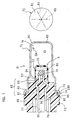
Fig. 1 is a built-up sectional view showing a gas generator of the
present invention; Fig. 2 is an exploded sectional view showing a gas generator
of the present invention; Fig. 3 is a sectional view, taken on line A-A of Fig. 1;
Fig. 4 is an enlarged sectional view of a principle part of Fig. 1; Fig. 5 is a
built-up sectional view showing a first variant of a gas generator of the present
invention; Fig. 6 is a built-up sectional view showing a second variant of a gas
generator of the present invention; Fig. 7 is a built-up sectional view showing
another gas generator of the present invention; Fig. 8 is an exploded sectional
view showing a gas generator of the present invention; Fig. 9 is an enlarged
sectional view of a principle part of Fig. 7; Fig. 10 is a built-up sectional view
showing a variant of a gas generator of the present invention; Fig. 11 is a
sectional view showing a conventional gas generator.
BEST MODE FOR CARRYING OUT THE INVENTION
-
An embodiment of a gas generator of the present invention will be
given with reference to the drawings.
-
A gas generator G shown in Figs. 1 and 2 is what actuates a
pretensioner for seat belts of an automobile. Gas generants P are burned by
ignition of a squib S then a large amount of gas generates rapidly. The gas
generator G includes a cup case 1, a tube-like case 2, and a holder 3 in addition
to the squib S and the gas generants P. The holder 3 is made of resin by insert
molding. A reinforcement 4 is integrated with the holder 3 so as to cover an
outer surface of the holder 3. In the gas generator G of the present invention, for
the purpose of crimping, an edge of the cup case 1 on an opening side is bent
onto the reinforcement 4 so as to cover an outer periphery of the reinforcement 4.
Thereby, the cup case 1 is sealed up. And then, inter-gaps among of the cup case
1, the tube-like case 2 and the holder 3 are tightly closed at the same time.
The squib S includes ignition charge 6, two electrode pins 7, 8, a bridge wire 9,
an fuse head 10 and a container body 5. The container body 5 has a cylindrical
shape with a bottom for containing the ignition charge 6, leading edges of the
two electrode pins 7, 8, the bridge wire 9 and the fuse head 10. And the squib
S is integrated with the holder 3.
-
The cup case 1 of the gas generator G has a cylindrical shape with a
bottom, of which a diameter becomes large in step-by-step, and made of metal
materials such as stainless or aluminum. The cup case 1 is loaded with the gas
generants P that generate gas by combustion. Step portions are formed in the cup
case 1, of which diameters increase from the bottom 11 side towards the opening
side. A plurality of notches 13 (e.g. six notches in Fig. 1) are formed with the
bottom 11 of the cup case 1. Each of the notches 13 is radially arranged from
an axis of the cup case 1 and carved with a predetermined depth within the cup
case 1. When the bottom 11 of the cup case 1 is partially spread in accordance
with an increase of internal pressure in the cup case 1, the notches 13 form a gas
discharge hole so as to communicate the inside and an outside of the cup case 1.
-
The tube-like case 2 is made of metal materials such as stainless or
aluminum and formed into a cylindrical shape, which disposed within the cup
case 1. The cylindrical tube-like case 2 is a cylinder of which a diameter
increases in step-by-step. One opening of the tube-like case 2 on a smaller
diameter side is an inflammation hole 16. A flange 17 is formed at an end
portion of the tube-like case 2 on a larger diameter opening side as a portion
projecting until a step portion 12 of the cup case 1. The flange 17 abuts the
step portion 12 within the cup case 1 and forms a combustion chamber N for the
gas generants P with the cup case 1. The container body 5 of the squib S is
inserted in the tube-like case 2 until the inflammation hole 16 is closed by the
container body 5. The ignition charge 6 are contained in the container body 5.
-
The holder 3 includes a holder's main body 18 and a shaft body 19
of which diameter decreases with two-stages from the holder's main body 18.
Therefore, a shape of the holder 3 has shoulder portions. The shaft body 19 is
fitted in the opening of the tube-like case 2. A fitting hole 20 for a plug is
formed in the holder's main body 18, which opens toward an opposite side to the
shaft body 19. A tip portion of the shaft body 19 is inserted in the container
body 5. The tip of the shaft body 19 has a fitting groove 22 in which a
protrusion 21 on an opening side of the container body 5 is fitted. The holder
3 is made by means of injecting resin containing glass fibers and the like into a
mold (not shown). As examples of the resin, there are polybutylene
terephthalate, polyethylene terephthalate, nylon 6, nylon 66, polyphenylene
sulfide, and polyphenylene oxide.
-
Electrode pins 7, 8 of the squib S and a reinforcement 4 are
integrated with the holder 3. Such holder is obtained by the following insert
molding. The respective electrode pin 7, 8 and the reinforcement 4 are
prepared in the above-mentioned mold in advance. Then, resin is injected into
the mold. The resinous holder 3 integrally formed with the electrode pins 7 , 8
and the reinforcement 4 is hereby obtained.
-
The respective electrode pin 7, 8 is arranged in parallel with an axis
of the gas generator G and penetrates the shaft body 19 of the holder 3. The
respective electrode pin 7, 8 has a curvature shape in the shaft body 19 . And the
respective electrode pin 7, 8 protrudes in the fitting hole 20 of the holder's main
body 18 and the container body 5. The respective electrode pin 7, 8 is made of
conductive materials such as stainless, iron-nickel alloy and electrically insulated
by the resin of the holder 3. Further, the bridge wire 9 is welded to the
respective electrode pin 7, 8 in the container body 5 by welding and the like.
The fuse head 10 is formed so as to cover tip portions of the respective electrode
pin 7, 8 and the bridge wire 9. And the fuse head 10 is in contact with the
ignition charge 6 in the container body 5. Thus, the holder 3 is integrally
provided with the squib S which includes the container body 5, the ignition
charge 6, the respective electrode pin 7, 8 and the like.
-
As examples of materials of the reinforcement 4, there are metal
materials such as stainless and SPCC and reinforced plastics such as heat curing
resin and the like. The reinforcement 4 is formed so as to have a cup shape
with a cylindrical body 23 and a ring plate 24. The cylindrical body 23 covers
an outer periphery of the holder's main body 18 so as to be a protruding portion.
And the ring plate 24 is substantially perpendicularly connected to the
cylindrical body 23. A corner of junction in which the cylindrical body 23 and
the ring plate 24 are connected, is chamfered.
-
The ring plate 24 is located between the holder's main body 18 and
the shaft body 19, and perpendicular to the respective electrode pins 7, 8. One
portion on an inner periphery side of the ring plate 24 is integrated with the resin
holder 3. Other portion on outer periphery side of the ring plate 24 is partially
exposed to an out of the holder 3. The portion of the ring plate 24 exposed to
the out of the holder 3 constructs the protruding portion with the cylindrical
body 23. As shown in Fig. 3, the respective electrode pin 7, 8 passes through
in an inner periphery hole 25 of the ring plate 24.
-
The gas generator G constructed as thus is manufactured in the
following steps.
-
The resinous holder 3 is obtained by the following insert molding,
which is integrated with the respective electrode pin 7, 8 and the reinforcement 4.
The respective electrode pins 7, 8 and the reinforcement 4 are set in a mold for
molding the holder 3 in advance. Resin is injected into the mold. The resinous
holder 3 is obtained, which is integrated with the respective electrode pin 7, 8
and the reinforcement 4.
-
Then, the bridge wire 9 is welded to the respective electrode pin 7, 8
and covered with the fuse head 10. The ignition charge 6 is contained in the
container body 5. The shaft body 19 of the holder 3 is fitted into the container
body 5, thereby the squib S and the holder 3 are integrated.
-
Then, a sealing ring 28 is mounted on the chamfered corner portion
of the outer periphery side of the reinforcement 4 of the holder 3. The
container body 5 of the squib S of the holder 3 is fitted into the tube-like case 2
until the container body 5 touches a bottom 15 of the tube-like case 2 so as to
close the inflammation hole 16 of the tube-like case 2. The shaft body 19 of the
holder 3 is inserted into the tube-like case 2 until the shaft body 19 touches a
step portion 29 of the tube-like case 2 so that the flange 17 of the tube-like case
2, the ring plate 24 and the sealing ring 28 are touched by one another. Thus,
the shaft body 19 of the holder 3 is fitted in an opening of the tube-like case 2.
The tube-like case 2 is thereby assembled on the holder 3.
-
Then, the tube-like case 2 assembled on the holder 3 is fitted into the
cup case 1. The holder 3 is inserted into the cup case 1 until the flange 17 of the
tube-like case 2 abuts the step portion 12 inside of the cup case 1. The
cylindrical body 23 of the reinforcement 4 is fitted in the opening of the cup
case 1. The gas generator G is thereby assembled.
-
Hereby, the tube-like case 2 and the container body 5 of the squib S,
etc. are accommodated in the cup case 1. The tube-like case 2 and the cup case 1
construct the combustion chamber N. The flange 17 of the tube-like case 2 is
located between the step portion 12 of the cup case 1 and the ring plate 24. In
other words, the step portion 12 of the cup case 1, the flange 17 of the tube-like
case 2 and the ring plate 24 are arranged in this order from the bottom 11 of the
cup case 1 and touch one another.
-
In the above-mentioned condition, as shown in Fig. 4, an edge on the
opening side of the cup case 1 is bent towards the holder 3 for the purpose of
crimping. The cylindrical body 23 of the reinforcement 4 is folded by the bent
portion 30 and the step portion 12 with crimping force.
-
Thereby, the step portion 12 and the flange 17 of the tube-like case 2
are pushed towards the ring plate 24 by the crimping force, then the sealing ring
28 is deformed. Inter-gaps amog of the cup case 1, tube-like case 2 and the ring
plate 24 are tightly closed.
-
Even when the crimping force acts on the holder 3 through the
flange 17 of the tube-like case 2, the reinforcement 4 consist of the ring plate 24
and the cylindrical body 23 prevents the holder 3 from deforming.
-
In the gas generator G, electric current flows through the electrode
pins 7, 8, and heat generated in the bridge wire 9 ignites the fuse head 10 then
the ignition charge 6 are subsequently fired. A flame of ignition of the squib S is
ejected into the cup case 1. The gas generants P are ignited and burned by the
flame, then a large amount of gas generated. In succession, the large amount
of gas is introduced from the cup case 1 to the above-mentioned seat belt
pretensioner through the gas discharge hole which opens by means of rupture at
the notches 13 of the bottom 11 in accordance with an increase of an internal
pressure in the cup case 1. The seat belt pretensioner is actuated by the high
pressure gas then fasten seat belts.
-
In the gas generator G of the present invention, the reinforcement 4
prevents the holder 3 form being deformed by the crimping force even if the
holder 3 was formed of resin. Also, the reinforcement 4 prevents the holder 3
from being deformed by a thermal expansion. Particularly, a construction in
which the flange 17 of the tube-like case 12 touches the ring plate 24 of the
reinforcement 4, prevents the crimping force from acting on the resin of the
holder 3 directly. Therefore, it is prevented that gaps arise by the crimping
force, thermal expansion and the like. Accordingly, it is also prevented that
water and the like enters the tube-like case 2 and the like. As a result,
performance of the gas generator G is ensured over a long period of time of use.
-
In the gas generator G of the present invention, since the crimping
force acts between the cup case 1 and the reinforcement 4 of the holder 3, a high
accuracy in crimping position is not required. Therefore, by a simple
construction of the present invention, the inter-gaps among of the cup case 1, the
tube-like case 2 and the holder 3 are tightly closed.
-
Since the inter-gaps among of the cup case 1, the tube-like case 2
and the holder 3 are integrally sealed by the crimping force acting substantially
between the cup case 1 and the reinforcement 4, a number of crimping members
such as sealing rings can be decreased. Therefore, the gas generator G can be
provided, which has an excellent durability and of which cost for manufacturing
is reduced.
-
The gas generator G having the cup-shaped reinforcement 4 has been
described. However, the gas generator G is not limited to the above-mentioned
gas generator. The reason in which the reinforcement 4 is formed into a cup
shape, is that a strength of the holder 3 is increased by the ring plate 24 and the
cup case 1 mounts and is fixed on the cylindrical body 23 easily by crimping
force. Standing at these points, the reinforcement shown in Figs. 5 and 6 may be
adopted.
-
A reinforcement 4 shown in Fig. 5 is only formed with a ring plate
35. An outer periphery side of the ring plate 35 protrudes from the holder 3 so
as to form a protruding portion 37 and an inner periphery side thereof is
integrated with the resin of the holder 3. In a condition in which the protruding
portion 37 of the ring plate 35 is fitted in an opening of the cup case 1, an edge
of the cup case 1 on the opening side is bent towards the holder 3 for the
purpose of crimping. The protruding portion 37 of the ring plate 35 is folded
by the bent portion 30 and the step portion 12 with crimping force. Thereby,
inter-gaps among of the cup case 1, the tube-like case 2 and the holder 3 are
tightly closed.
-
Fig. 5 shows a construction in which the flange 17 of the tube-like
case 2 abuts the holder's main body 18 without touching the protruding portion
37 of the ring plate 35. However, a construction may be adopted, in which the
protruding portion 37 of the ring plate 35 touches the flange 17 of the
tube-like case 2.
-
A reinforcement 4 shown in Fig. 6 is only formed with a cylindrical
body 36. An outer periphery side of the cylindrical body 36 protrudes from the
holder 3 so as to form a protruding portion 38 and an inner periphery side
thereof is integrated with the resin of the holder 3. In a condition in which the
protruding portion 38 of the cylindrical body 36 is fitted in an opening of the
cup case 1, an edge of the cup case 1 on an opening side is bent towards the
holder 3 for the purpose of crimping. The protruding portion 38 of the
cylindrical body 36 is folded by the bent portion 30 and the step portion 12 with
crimping force. Thereby, inter-gaps among of the cup case 1, the tube-like case
2 and the holder 3 are tightly closed.
-
Fig. 6 shows a construction in which the flange 17 of the tube-like
case 2 touches the holder's main body 18 without touching the protruding portion
38 of the cylindrical body 36. However, a construction may be adopted, in
which the protruding portion 38 of the cylindrical body 36 touches the flange 17
of the tube-like case 2.
-
Further, the another embodiment of the present invention will be
given with reference to the drawings.
-
Similarly to the above-mentioned gas generator, gas generators G for
actuating a pretensioner for seat belt of an automobile are shown in Figs. 7 and
8. In addition to a squib S and gas generants P, the respective gas generator G
includes a cup case 71 in a cylindrical shape with a bottom loaded with the gas
generants P, a container body 72 in a cylindrical shape with a bottom included in
the squib S, a holder 73, and a ring body 74 for crimping. The holder 73 is
made of resin. In the gas generator G, inter-gap between the cup case 71 and
the holder 73 is tightly closed by using the ring body 74 for crimping. The
squib S includes ignition charge 76, two electrode pins 77, 78, a bridge wire 79
and an fuse head 80 in addition to the container body 72. The squib S is
integrated with the holder 73.
-
The cup case 71 of the gas generator G is made of metal materials
such as stainless or aluminum into a cup shape and loaded with the gas generants
P that generate gas by combustion. A diameter of the cup case 71 increases
from a bottom 81 side to an opening side with step portions. A flange 82 is
integrally formed on an opening portion of the cup case 71, which extends in an
outwardly radial direction of the cup case 71. A plurality of notches 83, e.g.
six notches, are formed on the bottom 81 of the cup case 71, which are radially
arranged at an axis of the cup case 71 and notched with a predetermined depth
inside of the cup case 71. The notches 83 enable a gas discharge hole to open
on the bottom 81 in accordance with an increase of an internal pressure in the
cup case 71. Thereby, the inside and outside of the cup case 71 are
communicated through the gas discharge hole.
-
The container body 72 is disposed inside of the cup case 71. The
container body 72 is, for example, made of resin into a cup shape and contains
the ignition charge 76. An annular protrusion 94 is integrally formed at an
opening portion of the container body 72, which protrudes in the inwardly radial
direction of the container body 72.
-
The holder 73 has a holder's main body 88 and a shaft body 89
integrally. A fitting hole 90 for a plug is formed in the holder's main body 88,
which opens towards a side opposite to a shaft body side. A diameter of the
shaft body 89 decreases from a holder's main body side to a tip end side thereof
with three stages. Therefore, a shape of the shaft body 89 has shoulder
portions, a mounted shaft 91 mounted by the ring body 74, an inserted shaft 92
inserted into the cup case 71 and a fitted shaft 93 fitted into the container body
72. An annular fitting groove 97 is formed on the fitted shaft 93 of the shaft
body 89, in which the protrusion 94 of the container body 72 is fitted. The
holder 73 is preferably formed by injecting resin containing glass fibers and the
like into a mold (not shown). As examples of the resin, there polybutylene
terephthalate, polyethylene terephthalate, nylon 6, nylon 66, polyphenylene
sulfide, polyphenylene oxide and the like.
-
The holder 73 is integrally provided with electrode pins 77, 78, a
bridge wire 79 and an fuse head 80 in addition to the container body 72 of the
squib S and the ignition charge 76. The holder 73 is formed by the following
insert molding. The electrode pins 77, 78 are set in the above-mentioned
mold in advance. Then resin is injected into the mold. As a result, the resinous
holder 73 is obtained, which is integrated with the electrode pins 77, 78.
-
The electrode pins 77, 78 are arranged in parallel to an axis of the
holder 73 and penetrate shaft body 89 of the holder 73. The respective
electrode pin 77, 78 has a curve portion in the shaft body 89 and protrudes into
the fitting hole 90 of the holder's main body 88 and the container body 72. The
respective electrode pin 77, 78 is made of conductive materials such as stainless
or iron-nickel alloy and electrically insulated by the resin of the holder 73.
The bridge wire 79 is welded by welding and the like to the respective electrode
pin 77, 78 in the container body 72. The bridge wire 79 generates heat when
electric current flows through between the electrode pins 77, 78, then the fuse
head 80 is ignited. The fuse head 80 is formed so as to cover tip end portions
of the respective electrode pin 77, 78 and the bridge wire 79. The fuse head 80
is contacted with the ignition charge 76 in the container body 72.
-
The ring body 74 is made of metal materials such as stainless or
aluminum and into a cylindrical shape. An inside diameter of the ring body 74
is substantially equal to an outside diameter of the mounted shaft 91. The ring
body 74 is mounted on an outer periphery of the mounted shaft 91 of the holder
73 by being press-fitted. Thereby, it is prevented that the ring body 74 falls off
from the mounted shaft 91. Because the ring body 74 is connected to the
mounted shaft 91 of the holder 73 with friction. For connecting the ring body 74
to the mounted shaft 91 of the holder 73, the following constructions may be
adopted as well as the above-mentioned frictional contact. (i) A construction
in which an inner periphery of the ring body 74 and an outer periphery of the
mounted shaft 91 have screws-threads respectively, and then the ring body 74
and the mounted shaft 91 are connected each other by threaded engagement 74.
(ii) A construction in which the ring body 74 is mounted on an outer periphery
of the mounted shaft 91 of the holder 73 then the ring body 74 is coupled to the
mounted shaft 91 with a bolt and the like.
-
An edge of the ring body 74 on the cup case 71 side is bent towards
a flange 82 of the cup case 71 for crimping. And an inter-gap between the cup
case 71 and the holder 73 is tightly closed.
-
The gas generator G constructed as above is manufactured in the
following steps.
-
The cup case 71 and the container body 72 are made in advance so
as to have cup shapes respectively. Also, the ring body 74 is made in advance so
as to have a cylindrical shape. The gas generants P are loaded in the cup case
71 and the ignition charge 76 are loaded in the container body 72. The
following insert molding steps are carried out in order to obtain the resinous
holder 73 including the electrode pins 77, 78 integrally. The electrode pins 77,
78 are set in a mold in advance. Resin is injected into the mold. The resinous
holder 73 is obtained, which is integrated with the respective electrode pin 77,
78. Tip portions of the electrode pins 7,8, which project from the shaft body 89
of the holder 73, are respectively welded to the bridge wire 79. The fuse head
80 covers the bridge wire 79 and the like.
-
Then, the fuse head 80 of the squib S integrated with the holder 73 is
inserted into the container body 72. And the fitted shaft 93 of the holder 73 is
fitted into the container body 72. The bridge wire 79, the fuse head 80 and the
like are contained in the container body 72 under a condition where the fuse
head 80 is in contact with the ignition charge 76. The squib S is integrated
with the holder 73. The container body 72 of the holder 73 is inserted into the
cup case 71. And the inserted shaft 92 is inserted into an opening portion of
the cup case 71. At this time, the flange 82 of the cup case 71 touches a first
shoulder portion 96 formed between the mounted shaft 91 and the inserted shaft
92 of the holder 73. Thereby, a combustion chamber N is formed. Therefore,
the holder 73 is made an enclosed space for containing the gas generants P in
the cup case 71 as well as the enclosed space for containing the ignition charge
76 in the container body 72.
-
After the holder 73 is fitted into the cup case 71, the cup case 71 is
inserted into an opening of the ring body 74. The ring body 74 is mounted on
an outer periphery of the mounted shaft 91 of the holder 73 and an outer
periphery of the flange 82 of the cup case 71 by press- fitting. One edge of the
ring body 74 abuts a second shoulder portion 95 formed between the holder's
main body 88 and the mounted shaft 91. Other edge of the ring body 74
protrudes beyond the flange 82 towards the bottom side of the cup case 71 by a
predetermined length which enables crimping. (See Fig. 8).
-
For the purpose of crimping, as shown in Fig.9, the other edge
portion 75 of the ring body 74 protruding towards the bottom side of the cup
case 71 is bent towards the opening side of the cup 71, i.e. the flange 82 side,
with crimping force. The flange 82 of the cup case 71 is pushed on the first
shoulder portion 96 of the holder 73 by the crimping force. The inter-gap
between the cup case 71 and the holder 73 are tightly closed. In the manner
described above , the gas generator G is manufactured.
-
The crimping force on the ring body 74 is restrained by the metallic
flange 82 of the cup case 71, so that the crimping force does not act on the resin
of the holder 73 directly then the holder is not deformed.
-
In this gas generator G, when electric current flows through the
electrode pins 77, 78, heat arises in the bridge wire 79 then ignites the fuse head
80. And subsequently the ignition charge 76 are fired. Flames of the squib S are
ejected from the container body 72 into the cup case 71. By the flames, the gas
generants P are ignited and burned, then a large amount of gas generates. The
large amount of gas generated in the cup case 71 flows into the seat belt
pretensioner with a rush through the gas discharge hole which opens by means of
that the bottom 81 of the cup case 71 ruptures partially at the respective notch
83 in accordance with increase of internal pressure in the cup case 71. The
seat belt pretensioner is actuated by the high pressure gas flowing thereto, then
fastens seat belt.
-
In the gas generator G of the present invention, even when the holder
73 is made of resin, a gap between the cup case 71 and the holder 73 can be
tightly closed by means of a simple crimping operation in which the ring body
74 push onto the flange 82 of the cup case 71 with crimping force without high
accuracy in crimping position. In other words, an accuracy in crimping position
and precision devices for crimping etc. are not required.
-
Instead of a construction in which the end portion of the cup case 71
is directly folded onto the holder 73 for crimping, a construction in which the
end portion of the ring body 47 is folded onto the flange 82 of the cup case 71
for crimping, is adopted in the present invention. As a result, it is restrained
that a crimping force acts on the resin of the holder 73 directly through the
flange 82 of the cup case 71. Thereby deformation of the holder 73 is prevented.
Particularly, when the cup case 71 is made of metal material, it is surely
prevented that the crimping force acts on the resin of the holder 73 directly .
-
As a result, cost for manufacturing the gas generator G is decreased.
Also, it is prevented that gaps are made by deformation of the holder 73.
Therefor, water and the like does not enter the tube-like case and a performance
of the gas generator G is ensured over a long period of time of use. A gas
generator with excellent durability, of which cost of manufacture is reduced, can
be hereby provided.
-
In the gas generator G of the present invention, tight couplings
among of the ring body 74, the cup case 71 and the holder 73 are improved
when a sealing layer 100 is provided among of the ring body 74, the cup case 71
and the holder 73 as shown in Figs. 7 and 8. Consequently, the gas generator
has an excellent durability. Adhesives such as epoxy resin and silicon tapes etc.
may be used as sealing materials for the sealing layer 100. It is preferable to use
adhesive as sealing materials in order to strengthen a connection between the
ring body 74 and the holder 73.
-
Before the ring body 74 is mounted on the holder 73, adhesive is
applied to the ring body 74. The sealing layer 100 consisting of the adhesive is
formed among of the ring body 74, the cup case 71 and the holder 73. In
another case, in advance, an adhesive is applied onto some portions of the holder
73 and the cup case 71. The some portions should be in contact with the ring
body 74. After that, the ring body 74 mounts on. Thus, the sealing layer 100
may be formed.
-
The ring body 74 is not limited to the ring body made of such metal
material as stainless or aluminum. Any ring body 74 may be employed so long
as the ring body 74 can be folded towards the opening side of the cup case 71
after fixing on the holder 73 and pushed onto the flange 82 of the cup case 71
for crimping. For example, if the above condition is fulfilled, the ring body 74
may be made of resin.
-
Further, a ring body 104 shown in Fig. 10 may be adopted in the gas
generator G of the present invention. The ring body 104 shown in Fig. 10 is
formed into a cup shape with a cylindrical member 101 and a ring-shaped plate
member 102 connected substantially perpendicular to the cylindrical member 101.
The ring body 104 is made of metal materials, such as stainless or aluminum, or
resin etc.
-
The cup case 71 is inserted in the ring body 104 shown in Fig. 10.
The cylindrical member 101 mounts on an outer periphery of the mounted shaft
91 of the holder 73. The ring-shaped plate member 102 abuts the flange 82 of
the cup case 71 on an opening side thereof. The flange 82 of the cup case 71 is
sandwiched in between the ring-shaped plate member 102 of the ring body 104
and the first shoulder portion 96 of the holder 73 . Consequently, a gap between
the cup case 71 and the holder 73 is closed. At this time, in order to improve
the seal property, the following operation may be carried out. The ring-shaped
plate member 102 of the ring body 104 is pushed onto the flange 82 of the cup
case 71 with crimping force, as an effect, the flange 82 of the cup case 71 is
forced onto the holder 73. According to the ring body 104, such an operation
of bending the ring body 74 as shown in Fig. 7 towards the opening side of the
cup case 71 is omitted. And it is prevented that the resin of the holder 73 is
deformed by the bending force. Also, a cost for manufacturing the gas
generator G may be decreased since the bending operation is not necessary.
-
When a sealing layer 100 such as an adhesive is formed among of
the cylindrical member 101 and the ring-shaped plate member 102 of the ring
body 104, the cup case 71 and the holder 73, a seal property is improved as well
as described in Fig. 7.
-
Further, it is preferable that, in the ring body 104, an inside diameter
of the cylindrical member 101 is substantially equal to an outside diameter of a
mounted shaft 91 and an inside diameter of the ring-shaped plate member 102 is
substantially equal to an outside diameter of the cup case 71 on an opening side
thereof. Thereby, when the ring body 104 is mounted on the holder 73, the
seal property among of the ring body104, the cup 71 and the holder 73 is
improved by friction contact of the above-mentioned components since the
cylindrical member 101 and the plate member 102 are respectively press-fitted
on the outer periphery of the mounted shaft 91 and the outer periphery of the
cup 71 on the opening side thereof.
INDUSTRIAL APPLICABILITY
-
The gas generator of the present invention is most suitable for
occupant safety systems such as seat belt pretensioner since the present
invention has the excellent durability and the manufacturing cost is reduced.