EP4491993A1 - Header tube, heat exchanger, air conditioner, and method for manufacturing header tube - Google Patents
Header tube, heat exchanger, air conditioner, and method for manufacturing header tube Download PDFInfo
- Publication number
- EP4491993A1 EP4491993A1 EP23766967.6A EP23766967A EP4491993A1 EP 4491993 A1 EP4491993 A1 EP 4491993A1 EP 23766967 A EP23766967 A EP 23766967A EP 4491993 A1 EP4491993 A1 EP 4491993A1
- Authority
- EP
- European Patent Office
- Prior art keywords
- header tube
- tab members
- tab
- tip
- heat exchanger
- Prior art date
- Legal status (The legal status is an assumption and is not a legal conclusion. Google has not performed a legal analysis and makes no representation as to the accuracy of the status listed.)
- Pending
Links
Images











Classifications
-
- F—MECHANICAL ENGINEERING; LIGHTING; HEATING; WEAPONS; BLASTING
- F28—HEAT EXCHANGE IN GENERAL
- F28F—DETAILS OF HEAT-EXCHANGE AND HEAT-TRANSFER APPARATUS, OF GENERAL APPLICATION
- F28F9/00—Casings; Header boxes; Auxiliary supports for elements; Auxiliary members within casings
- F28F9/02—Header boxes; End plates
- F28F9/0219—Arrangements for sealing end plates into casing or header box; Header box sub-elements
- F28F9/0224—Header boxes formed by sealing end plates into covers
-
- F—MECHANICAL ENGINEERING; LIGHTING; HEATING; WEAPONS; BLASTING
- F28—HEAT EXCHANGE IN GENERAL
- F28F—DETAILS OF HEAT-EXCHANGE AND HEAT-TRANSFER APPARATUS, OF GENERAL APPLICATION
- F28F9/00—Casings; Header boxes; Auxiliary supports for elements; Auxiliary members within casings
- F28F9/02—Header boxes; End plates
- F28F9/026—Header boxes; End plates with static flow control means, e.g. with means for uniformly distributing heat exchange media into conduits
-
- B—PERFORMING OPERATIONS; TRANSPORTING
- B23—MACHINE TOOLS; METAL-WORKING NOT OTHERWISE PROVIDED FOR
- B23K—SOLDERING OR UNSOLDERING; WELDING; CLADDING OR PLATING BY SOLDERING OR WELDING; CUTTING BY APPLYING HEAT LOCALLY, e.g. FLAME CUTTING; WORKING BY LASER BEAM
- B23K1/00—Soldering, e.g. brazing, or unsoldering
- B23K1/0008—Soldering, e.g. brazing, or unsoldering specially adapted for particular articles or work
- B23K1/0012—Brazing of heat exchangers
-
- F—MECHANICAL ENGINEERING; LIGHTING; HEATING; WEAPONS; BLASTING
- F28—HEAT EXCHANGE IN GENERAL
- F28F—DETAILS OF HEAT-EXCHANGE AND HEAT-TRANSFER APPARATUS, OF GENERAL APPLICATION
- F28F9/00—Casings; Header boxes; Auxiliary supports for elements; Auxiliary members within casings
- F28F9/02—Header boxes; End plates
- F28F9/0202—Header boxes having their inner space divided by partitions
- F28F9/0204—Header boxes having their inner space divided by partitions for elongated header box, e.g. with transversal and longitudinal partitions
- F28F9/0209—Header boxes having their inner space divided by partitions for elongated header box, e.g. with transversal and longitudinal partitions having only transversal partitions
- F28F9/0212—Header boxes having their inner space divided by partitions for elongated header box, e.g. with transversal and longitudinal partitions having only transversal partitions the partitions being separate elements attached to header boxes
-
- F—MECHANICAL ENGINEERING; LIGHTING; HEATING; WEAPONS; BLASTING
- F28—HEAT EXCHANGE IN GENERAL
- F28F—DETAILS OF HEAT-EXCHANGE AND HEAT-TRANSFER APPARATUS, OF GENERAL APPLICATION
- F28F9/00—Casings; Header boxes; Auxiliary supports for elements; Auxiliary members within casings
- F28F9/02—Header boxes; End plates
- F28F9/026—Header boxes; End plates with static flow control means, e.g. with means for uniformly distributing heat exchange media into conduits
- F28F9/028—Header boxes; End plates with static flow control means, e.g. with means for uniformly distributing heat exchange media into conduits by using inserts for modifying the pattern of flow inside the header box, e.g. by using flow restrictors or permeable bodies or blocks with channels
-
- F—MECHANICAL ENGINEERING; LIGHTING; HEATING; WEAPONS; BLASTING
- F28—HEAT EXCHANGE IN GENERAL
- F28D—HEAT-EXCHANGE APPARATUS, NOT PROVIDED FOR IN ANOTHER SUBCLASS, IN WHICH THE HEAT-EXCHANGE MEDIA DO NOT COME INTO DIRECT CONTACT
- F28D1/00—Heat-exchange apparatus having stationary conduit assemblies for one heat-exchange medium only, the media being in contact with different sides of the conduit wall, in which the other heat-exchange medium is a large body of fluid, e.g. domestic or motor car radiators
- F28D1/02—Heat-exchange apparatus having stationary conduit assemblies for one heat-exchange medium only, the media being in contact with different sides of the conduit wall, in which the other heat-exchange medium is a large body of fluid, e.g. domestic or motor car radiators with heat-exchange conduits immersed in the body of fluid
- F28D1/04—Heat-exchange apparatus having stationary conduit assemblies for one heat-exchange medium only, the media being in contact with different sides of the conduit wall, in which the other heat-exchange medium is a large body of fluid, e.g. domestic or motor car radiators with heat-exchange conduits immersed in the body of fluid with tubular conduits
- F28D1/053—Heat-exchange apparatus having stationary conduit assemblies for one heat-exchange medium only, the media being in contact with different sides of the conduit wall, in which the other heat-exchange medium is a large body of fluid, e.g. domestic or motor car radiators with heat-exchange conduits immersed in the body of fluid with tubular conduits the conduits being straight
- F28D1/0535—Heat-exchange apparatus having stationary conduit assemblies for one heat-exchange medium only, the media being in contact with different sides of the conduit wall, in which the other heat-exchange medium is a large body of fluid, e.g. domestic or motor car radiators with heat-exchange conduits immersed in the body of fluid with tubular conduits the conduits being straight the conduits having a non-circular cross-section
- F28D1/05366—Assemblies of conduits connected to common headers, e.g. core type radiators
-
- F—MECHANICAL ENGINEERING; LIGHTING; HEATING; WEAPONS; BLASTING
- F28—HEAT EXCHANGE IN GENERAL
- F28F—DETAILS OF HEAT-EXCHANGE AND HEAT-TRANSFER APPARATUS, OF GENERAL APPLICATION
- F28F2275/00—Fastening; Joining
- F28F2275/04—Fastening; Joining by brazing
-
- F—MECHANICAL ENGINEERING; LIGHTING; HEATING; WEAPONS; BLASTING
- F28—HEAT EXCHANGE IN GENERAL
- F28F—DETAILS OF HEAT-EXCHANGE AND HEAT-TRANSFER APPARATUS, OF GENERAL APPLICATION
- F28F2275/00—Fastening; Joining
- F28F2275/08—Fastening; Joining by clamping or clipping
- F28F2275/085—Fastening; Joining by clamping or clipping with snap connection
-
- F—MECHANICAL ENGINEERING; LIGHTING; HEATING; WEAPONS; BLASTING
- F28—HEAT EXCHANGE IN GENERAL
- F28F—DETAILS OF HEAT-EXCHANGE AND HEAT-TRANSFER APPARATUS, OF GENERAL APPLICATION
- F28F2275/00—Fastening; Joining
- F28F2275/12—Fastening; Joining by methods involving deformation of the elements
- F28F2275/122—Fastening; Joining by methods involving deformation of the elements by crimping, caulking or clinching
Definitions
- the present disclosure relates to a header tube, a heat exchanger, an air conditioner, and a method of manufacturing a header tube.
- Air conditioners accommodate refrigerant circulating between an indoor unit and an outdoor unit and thus heat or cool the indoor air.
- Each of the indoor unit and the outdoor unit of the air conditioner includes a heat exchanger.
- the heat exchanger causes heat exchange between refrigerant and the environment surrounding the indoor unit or the outdoor unit.
- the heat exchanger includes a heat transfer tube array including multiple heat transfer tubes, and header tubes connected to the heat transfer tube array.
- Patent Literature 1 discloses a heat exchanger, which includes a header tube manufactured through bonding a first member including a bottom plate and a pair of lateral plates to a second member by brazing. Each of the lateral plates is provided with tab members at the edge adjoining the second member, and the tab members are bent to come into contact with the second member.
- Patent Literature 1 Unexamined Japanese Patent Application Publication No. 2016-95086
- the air conditioner needs to have a structure in which refrigerant circulating in the air conditioner does not leek during circulation.
- the first member and the second member must be air-tightly bonded to each other in the header tube disclosed in Patent Literature 1.
- the header tube disclosed in Patent Literature 1 suffers from a problem that the gaps between the tab members and the second member are expanded at the tips of the tab members due to springback behaviors occurring after bending of the tab members. Such expanded gaps between the tab members and the second member may fail to retain droplets of a molten brazing material in the brazing process. These droplets of the brazing material may run downward and fail to be sufficiently distributed across the joint between the first member and the second member. The joint between the first member and the second member may accordingly have inferior airtightness. That is, the header tube disclosed in Patent Literature 1 cannot readily achieve an airtight structure at the joint between the first member and the second member in the manufacturing process.
- the present disclosure is made in view of the above problems, and an objective of the present disclosure is to provide a header tube that is manufactured by bending tab members of one member over the other member and thus fixing the other member relative to the one member, and then bonding these members to each other by brazing, and that can readily achieve an airtight structure in the manufacturing process.
- Another objective of the present disclosure is to provide a heat exchanger and an air conditioner including the above-described header tube. Still another objective of the present disclosure is to provide a method of manufacturing the above-described header tube.
- a header tube according to the present disclosure is connectable to heat transfer tubes arranged in parallel to each other, and is capable of constituting a heat exchanger together with the heat transfer tubes.
- the header tube according to the present disclosure includes: a first member including a bottom plate and a pair of lateral plates standing at opposed edges of the bottom plate; a second member disposed apart from the bottom plate, held between the pair of lateral plates, and bonded to the first member by brazing; and tab members disposed at edges of the pair of lateral plates of the first member.
- the tab members are bent relative to the lateral plate so as to face the second member.
- Each of the tab members is tapered toward the tip in plan view.
- header tube In the header tube according to the present disclosure, droplets of a molten brazing material, which is preliminarily cladded on the surface of a tab member to come into contact with the second member, run downward in the brazing process.
- the droplets of the molten brazing material are accumulated into a large thickness at the tip of the tab member, and thus readily come into contact with the second member.
- the accumulated brazing material can prevent a crack from being generated at the brazed joint due to the absence of the brazing material.
- the present disclosure can therefore provide a header tube that can readily achieve an airtight structure in the manufacturing process.
- FIG. 1 is an explanatory diagram illustrating a fundamental configuration of an air conditioner 1 according to an embodiment.
- the air conditioner 1 adjusts the temperature of the air in an indoor space (not illustrated) to be conditioned, and serves as a heater or cooler as required.
- the air conditioner 1 includes an outdoor unit 2 and an indoor unit 3.
- the air conditioner 1 also includes a pipe 4 between the outdoor unit 2 and the indoor unit 3.
- the pipe 4 allows refrigerant to flow therethrough and circulate between the outdoor unit 2 and the indoor unit 3.
- the outdoor unit 2 and the indoor unit 3 each include a heat exchanger 5 and a fan 6.
- the heat exchanger 5 causes heat exchange between refrigerant flowing through the heat exchanger 5 and the environment surrounding the heat exchanger 5.
- the fan 6 is a blower that sends the ambient air around the heat exchanger 5 to the heat exchanger 5, and thus facilitates the heat exchange.
- the outdoor unit 2 includes a compressor 7, a four-way valve 8, and an expansion valve 9.
- the compressor 7 performs adiabatic compression of refrigerant in a gas state.
- the four-way valve 8 switches the direction of refrigerant flow in the pipe 4.
- the expansion valve 9 reduces the pressure of refrigerant in a liquid state and thus evaporates the refrigerant.
- the four-way valve 8 is turned into a mode in which the air conditioner 1 serves as a heater.
- the refrigerant compressed by the compressor 7 and having an increased temperature flows into the heat exchanger 5 of the indoor unit 3, and discharges heat to the indoor air.
- the refrigerant that has flown through the heat exchanger 5 of the indoor unit 3 flows through the expansion valve 9 into the heat exchanger 5 of the outdoor unit 2, and absorbs heat from the outdoor air.
- the refrigerant then returns to the compressor 7.
- the four-way valve 8 is turned into another mode to reverse the direction of refrigerant flow, the refrigerant absorbs heat in the heat exchanger 5 of the indoor unit 3, and discharges heat in the heat exchanger 5 of the outdoor unit 2.
- the air conditioner 1 in this case serves as a cooler.
- FIG. 2A is a front view illustrating a fundamental configuration of the heat exchanger 5
- FIG. 2B is a side view of the heat exchanger 5.
- the heat exchanger 5 includes an upper header tube 11, a first lower header tube 12, and a second lower header tube 13.
- the first lower header tube 12 has a first inlet/outlet port 14, whereas the second lower header tube 13 has a second inlet/outlet port 15.
- the first inlet/outlet port 14 and the second inlet/outlet port 15 are each a pipe joint connected to the pipe 4 (not illustrated in FIG. 2B ).
- the first inlet/outlet port 14 and the second inlet/outlet port 15 allow refrigerant to enter or exit the heat exchanger 5.
- the first lower header tube 12 and the second lower header tube 13 have substantially the same structure, although this structure is not described in detail.
- the first lower header tube 12 and the upper header tube 11 are provided with a first heat transfer tube array 16 therebetween, which couples the first lower header tube 12 to the upper header tube 11.
- the second lower header tube 13 and the upper header tube 11 are provided with a second heat transfer tube array 17 therebetween, which couples the second lower header tube 13 to the upper header tube 11.
- the first heat transfer tube array 16 includes multiple heat transfer tubes 18 arranged at regular intervals in the longitudinal direction of the first lower header tube 12 and the upper header tube 11.
- the heat transfer tubes 18 have internal flow paths, which are not illustrated. These flow paths allow refrigerant to travel between the first lower header tube 12 and the upper header tube 11.
- the second heat transfer tube array 17 also includes multiple heat transfer tubes 18 arranged at regular intervals in the longitudinal direction of the second lower header tube 13 and the upper header tube 11.
- the heat transfer tubes 18 also have internal flow paths, which allow refrigerant to travel between the second lower header tube 13 and the upper header tube 11.
- multiple heat transfer fins 19 are arranged at regular intervals between the upper header tube 11 and the first and second lower header tubes 12 and 13.
- the heat transfer fins 19 are made of thin metal plates and physically coupled to the first heat transfer tube array 16 and the second heat transfer tube array 17.
- the heat transfer fins 19 facilitate heat transfer between the ambient air and the refrigerant flowing in the first heat transfer tube array 16 and the second heat transfer tube array 17.
- the above-described structure allows the refrigerant that has entered the first lower header tube 12 to flow through the heat transfer tubes 18 of the first heat transfer tube array 16 to the upper header tube 11.
- the refrigerant that has arrived at the upper header tube 11 flows through the heat transfer tubes 18 of the second heat transfer tube array 17 to the second lower header tube 13.
- the refrigerant that has arrived at the second lower header tube 13 is released to the outside via the second inlet/outlet port 15.
- the refrigerant travels in the route opposite to the above-described route, specifically, flows through the second heat transfer tube array 17, the upper header tube 11, and the first heat transfer tube array 16 in sequence, to the first lower header tube 12.
- the refrigerant that has arrived at the first lower header tube 12 is released to the outside via the first inlet/outlet port 14.
- the refrigerant flowing through the heat exchanger 5 travels inside the heat transfer tubes 18, as described above.
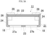
- FIG. 3A is a transverse sectional view of the upper header tube 11 taken along the plane represented by the line I-I of FIG. 2A .
- FIG. 3B is a longitudinal sectional view of a part of the upper header tube 11 taken along the plane represented by the line II-II of FIG. 2B .
- the upper header tube 11 is an example of a header tube according to the present disclosure, as described above.
- the upper header tube 11 includes a first member 21 and a second member 22.
- the first member 21 and the second member 22 are bonded to each other by brazing.
- the first member 21 is a metal component including a bottom plate 23 and a pair of lateral plates 24 standing at opposed edges of the bottom plate 23.
- the first member 21 as a whole has a channel-shape defining a groove.
- the second member 22 is a metal component disposed at a position apart from the bottom plate 23 of the first member 21, and held between the pair of lateral plates 24 of the first member 21. In short, the second member 22 corresponds to a lid of the groove defined by the first member 21. As illustrated in FIG.
- the space inside the upper header tube 11, that is, the space defined between the first member 21 and the second member 22 accommodates a corrugated plate 25.
- the lateral plates 24 of the first member 21 are provided with protruding columns 26 having a cylindrical shape on the inner surfaces. The specific shapes and functions of the corrugated plate 25 and the protruding columns 26 are described below.
- the bottom plate 23 of the first member 21 has insertion holes 27a and 27b.
- the insertion holes 27a receive the respective ends of the heat transfer tubes 18 of the first heat transfer tube array 16, and are bonded to the ends by brazing.
- the insertion holes 27b receive the respective ends of the heat transfer tubes 18 of the second heat transfer tube array 17, and are bonded to the ends by brazing.
- the lateral plates 24 of the first member 21 each have tab members 28 at the edge.
- the tab members 28 are bent relative to the lateral plates 24 so as to face the second member 22.
- the second member 22 is thus held between the corrugated plate 25 and the tab members 28.
- FIG. 3B is a longitudinal sectional view of a part of the upper header tube 11 adjacent to the left end in FIG. 2A .
- the upper header tube 11 has a part adjacent to the right end having the same structure as the part adjacent to the left end. That is, the upper header tube 11 is provided with another end plate 29 adjacent to the right end in the longitudinal direction of the upper header tube 11.
- the corrugated plate 25 is disposed between the first member 21 and the second member 22, as described above.
- the corrugated plate 25 has a wavy shape, as illustrated in FIG. 3B .
- This corrugated plate 25 divides the internal space of the upper header tube 11 into compartments each accommodating a pair of insertion holes 27a and 27b adjacent to each other.
- This structure causes the refrigerant that has entered the upper header tube 11 to travel within each of the compartments defined by the corrugated plate 25. For example, the refrigerant that has entered a certain compartment through the heat transfer tube 18 fixed to the corresponding insertion hole 27a flows into the heat transfer tube 18 fixed to the insertion hole 27b located adjacent to this insertion hole 27a, without flowing to the other compartments.
- the corrugated plate 25 meshes with the protruding columns 26, and is thus prevented from being displaced in the longitudinal direction of the upper header tube 11.
- the protruding columns 26 are designed to have a radius equal to the radius of curvature of curved portions of the corrugated plate 25, and arranged at the same pitch as those of the insertion holes 27a and 27b.
- the protruding columns 26 can thus align the corrugated plate 25 to the proper position relative to the insertion holes 27a and 27b just by meshing with the corrugated plate 25.
- the corrugated plate 25 holds the second member 22 against the tab members 28, as described above.
- the upper header tube 11 may exclude the corrugated plate 25.
- the internal space of the upper header tube 11 may be divided into multiple compartments by multiple end plates 29, specifically, three or more end plates 29 arranged in the longitudinal direction of the upper header tube 11, so as to prevent the second member 22 from being displaced toward the bottom plate 23 of the first member 21 across the longitudinal direction of the upper header tube 11.
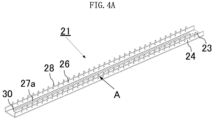
- FIG. 4A is a perspective view illustrating the external shape of the first member 21 that constitutes the upper header tube 11.
- FIG. 4B is a perspective view of the first member 21 after fitting of the second member 22 to the first member 21.
- FIG. 4C is an enlarged view of one of the tab members 28 of the first member 21 as seen in the direction represented by the arrow A of FIG. 4A .
- each of the tab members 28 in plan view has the maximum width at the proximal portion, that is, the portion adjoining the lateral plate 24.
- the tab member 28 is tapered toward the tip, that is, the portion most distant from the lateral plate 24.
- the tip of the tab member 28 is shaped to have an arc contour.
- the shape of the tab member 28 in plan view mentioned in this specification means the shape like that illustrated in FIG. 4C .
- the lengthwise direction of the tab member 28 indicates the direction from the proximal portion toward the tip of the tab member 28.
- the widthwise direction of the tab member 28 indicates the direction orthogonal to the lengthwise direction in the shape in plan view illustrated in FIG. 4C .
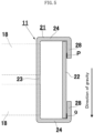
- FIG. 5 is a transverse sectional view of the upper header tube 11.
- the heat exchanger 5 is manufactured through assembling the components of the heat exchanger 5 with each other, heating the assembled components in a furnace, and then bonding the components to each other by brazing.
- the heat exchanger 5 is laid down during the brazing process for the heat exchanger 5, because of the limited height of the furnace. That is, the heat exchanger 5 is subject to the brazing process in the furnace such that the longitudinal axes of the heat transfer tubes 18 are horizontally oriented.
- the brazing process is applied to the heat exchanger 5 including the upper header tube 11 oriented as illustrated in FIG. 5 .
- the first member 21 and the second member 22 are preliminarily provided with a brazing material cladded on their surfaces.
- droplets of a molten brazing material in each of the gaps between the tab members 28 and the second member 22 located above in the first member 21 in FIG. 5 run downward due to gravity, to the tip of the tab member 28, that is, to the site represented by the reference symbol P in FIG. 5 .
- the tab member 28 has a larger width at the proximal portion and a smaller width at the tip as described above, droplets of the brazing material residing in the proximal portion of the tab member 28 having a larger width run down and are concentrated at the tip of the tab member 28 having a smaller width.
- the concentrated droplets of the molten brazing material form a large lump at the tip of the tab member 28 and thicken the tip.
- This lump of the brazing material can be retained between the tip of the tab member 28 and the second member 22, even if the gap between the tip of the tab member 28 and the second member 22 is expanded by a springback behavior occurring after bending of the tab member 28.
- the brazing material which is preliminarily cladded on the inner and outer surfaces of the second member 22 and the inner surface of the lateral plate 24, is molten by heating and infiltrates into the gap between the proximal portion of the tab member 28 and the second member 22, because of a capillary action generated at the gap. This brazing material fills the gap between the proximal portion of the tab member 28 and the second member 22, and the gap between the lateral plate 24 and the second member 22.
- the brazing material is thus sufficiently distributed across the joint between the first member 21 and the second member 22 located above in the first member 21.
- the capillary action draws the brazing material in the direction opposite to the direction of gravity, and thus gathers, to the gap, droplets of the brazing material residing in a large area around the gap between the first member and the second member.
- droplets of the molten brazing material in each of the gaps between the tab members 28 and the second member 22 located below in the first member 21 in FIG. 5 run downward due to gravity, to the site between the proximal portion of the tab member 28 and the second member 22, that is, the site represented by the reference symbol Q in FIG. 5 .
- the droplets are then accumulated at this site.
- the proximal portion of the tab member 28 defines a small gap against the second member 22 because the proximal portion of the tab member 28 is not readily affected by a deformation caused by a springback behavior. This small gap is filled with the run-off droplets of the brazing material.
- the capillary action causes the brazing material cladded on both surfaces of the lateral plate 24 to infiltrate into the gap between the first member 21 and the second member 22.
- the brazing material is thus also sufficiently distributed across the joint between the first member 21 and the second member 22 located below in the first member 21, as in the brazing material located above in the first member 21.
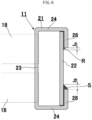
- the gaps between the tab members 28 and the second member 22 are filled with the brazing material.
- droplets of the brazing material are accumulated and then form fillets at the tips of the tab members 28, that is, the sites represented by the reference symbols R and S in FIG. 6 .
- the fillet formed at the site represented by the reference symbol S that is, the fillet formed at the tip of the tab member 28 located below in the FIG. 6 is larger than the fillet formed at the site represented by the reference symbol R, that is, the fillet formed at the tip of the tab member 28 located above in FIG. 6 .
- l R indicates the length of the fillet formed at the site represented by the reference symbol R
- l S indicates the length of the fillet formed at the site represented by the reference symbol S.
- a brazing material fillet formed at the tip of one of the two tab members 28, which are opposed to each other in the transverse direction of the upper header tube 11, has a different size from a brazing material fillet formed at the tip of the other of the tab members 28, in this embodiment.
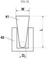
- FIG. 7A is a front view illustrating the shapes of a test piece 41 that imitates the tab member 28 and a jig 42 that retains the test piece 41 before an examination.
- FIG. 7B is a side view illustrating the shape of the test piece 41 after the examination, that is, after a step of heating the test piece 41 in a furnace, which is not illustrated, and thus melting the brazing material.
- the test piece 41 had a width W of 5 mm, a length L of 12 mm, and a thickness T of 3 mm, had smoothed surfaces, and was provided with a brazing material layer having a thickness of 0.15 mm. As illustrated in FIG. 7A , the test piece 41 had a semicircular tip. This examination involved comparison of the performances of test pieces 41 having different diameters D of the semicircular tips. Specifically, four types of test pieces 41 having diameters D of 1, 2, 3, and 4 mm were compared in terms of their performances.
- the jig 42 retained the test piece 41 in an upright orientation, while having no contact with the surfaces of the test piece 41. The jig 42 thus did not affect behaviors of the brazing material molten on the surfaces of the test piece 41.
- FIG. 7B droplets of the brazing material molten on the surface of the test piece 41 were concentrated at the tip of the test piece 41 having a smaller width and formed a lump 43.
- FIG. 7C illustrates a relationship between the value calculated by dividing the diameter D of the semicircular tip of the test piece 41 by the width W of the proximal portion of the test piece 41, that is, the ratio D/W and the measured height Hi of the lump 43 from the surface of the test piece 41, for each of the above-mentioned four types of test pieces 41. As illustrated in FIG.
- the height Hi of the lump 43 rose with an increase in the ratio D/W and reached 0.44 mm at the ratio D/W of 0.6, but lowered after the ratio D/W exceeded 0.6. That is, the maximum height Hi was achieved at the ratio D/W of 0.6.
- the lump 43 had a sufficient height when the ratio D/W was equal to or higher than 0.4, but suffered from an insufficient height when the ratio D/W was equal to or lower than 0.2.
- the diameters of 1, 2, 3, and 4 mm respectively provided the ratios D/W of 0.2, 0.4, 0.6, and 0.8, because the proximal portion of the test piece 41 used in this examination had a width W of 5 mm.
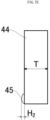
- FIG. 7D is a front view illustrating the shapes of another test piece 44 according to a comparative example and the jig 42 before an examination.
- FIG. 7E is a side view illustrating the shape of the test piece 44 after the examination, that is, after a step of heating the test piece 44 in a furnace, which is not illustrated, and thus melting the brazing material.
- the test piece 44 had a width W of 5 mm, a length L of 12 mm, and a thickness T of 3 mm, had smoothed surfaces, and was provided with a brazing material layer having a thickness of 0.15 mm cladded on the surfaces.
- the test piece 44 was different from the test piece 41 in that the test piece 44 had a rectangular shape having a constant width W between the proximal portion and the tip. As illustrated in FIG. 7E , the brazing material molten on the surface of the test piece 44 ran downward to the tip of the test piece 44 and formed a lump 45. The formed lump 45, however, had a height H 2 of only 0.36 mm from the test piece 44. The accumulated brazing material can be thickened by the ratio D/W equal to or higher than 0.4. The lump of the brazing material having a larger height can thus improve the capacity of brazing.
- the test piece 41 was able to concentrate the molten brazing material at the tip of the test piece 41 having a smaller width, and thus form a lump 43 of the brazing material at the tip of the test piece 41 having a larger height than that of the lump 45 of the brazing material formed at the tip of the test piece 44 under the same heating conditions for the test pieces 41 and 44.
- This result demonstrates that the molten brazing material can be concentrated at the tip of the tab member 28 and have a larger height, if the tab member 28 is designed to be tapered toward the tip in plan view.
- the brazing material is successfully concentrated at the tip of the tab member and accumulated into a large thickness.
- droplets of the brazing material are accumulated also in an area closer to the proximal portion of the tab member and results in a relatively smaller thickness, because of an excessively small width of the tip of the tab member.
- FIG. 8A is a plan view illustrating the shape of a tab member 28 according to Modification 1 of the present disclosure.
- the tab member 28 may have a constant width in a certain area from the proximal portion adjoining the lateral plate 24 to a middle portion, and may be gradually tapered from the middle portion toward the tip having the minimum width.
- FIG. 8B is a plan view illustrating the shape of a tab member 28 according to Modification 2 of the present disclosure.
- the tab member 28 may have a smaller width at the proximal portion adjoining the lateral plate 24, be widen from the proximal portion to a middle portion, and then be gradually tapered toward the tip having the minimum width. That is, the tab member 28 may have a constricted proximal portion in plan view.
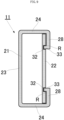
- FIG. 9 is a transverse sectional view illustrating the structure of an upper header tube 11 according to Modification 3 of the present disclosure in conformity with FIG. 5 .
- the upper header tube 11 has recesses 32 on the second member 22, and protrusions 33 at the tips of the tab members 28.
- the protrusions 33 are fitted in the respective recesses 32.
- This structure facilitates droplets of a molten brazing material to be accumulated in crank-shaped gaps R between the protrusions 33 and the recesses 32 in the brazing process.
- These droplets of the brazing material accumulated in the gaps R are distributed across the gaps between the first member 21 and the second member 22 due to a capillary action.
- the distributed brazing material can prevent a crack from being generated at the brazed joint between the first member 21 and the second member 22.
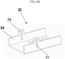
- FIG. 10A is a perspective view illustrating the shape of a first member 21 according to Modification 4.
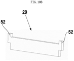
- FIG. 10B is a perspective view illustrating the shape of an end plate 29 according to Modification 4.
- FIG. 10C is a perspective view of the first member 21 after fitting of the end plate 29 to the first member 21.
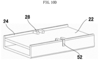
- FIG. 10D is a perspective view of the first member 21 after fitting of the end plate 29 and a second member 22 to the first member 21 and bending of tab members 28.
- FIG. 10E is an explanatory diagram illustrating the shapes of the tab members 28 and an engaging notch 51 of the first member 21 according to Modification 4, in conformity with FIG. 4C .
- the end plate 29 is fitted in the upper header tube 11 by engaging the edges of the end plate 29 with the engaging holes 30 and 31 of the bottom plate 23 and the second member 22 in the above-described example, the end plate 29 may also be fitted in the upper header tube 11 by a procedure other than the engaging holes 30 and 31.
- the engaging holes 30 and 31 may be replaced with engaging notches 51 provided to the edges of the two lateral plates 24 opposed to each other.
- the engaging notches 51 are each located between two tab members 28 adjacent to each other in the longitudinal direction of the first member 21 and extend from the edge of the lateral plate 24.
- the end plate 29 has ears 52 at the opposed edges. As illustrated in FIG.
- the ears 52 are inserted in the respective engaging notches 51 and engaged with the engaging notches 51, so that the end plate 29 is align to the proper position relative to the first member 21.
- the end plate 29 is covered with the second member 22, followed by a step of bending the tab members 28. These steps can fix the end plate 29 to the first member 21 and the second member 22.
- the engaging notches 51 have a width G 1 equal to the distance between the two tab members 28 at the proximal portions. Since each of the tab members 28 is tapered toward the tip, as described above, the two tab members 28 at the tips have a distance G 2 therebetween larger than the distance between the two tab members 28 at the proximal portions. The distance G 2 is thus larger than the thickness of the end plate 29.
- the tab members 28 having this structure can guide the ears 52 of the end plate 29 to be inserted in the engaging notches 51. The ears 52 can therefore be readily inserted in the engaging notches 51.
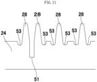
- FIG. 11 is an explanatory diagram illustrating the shapes of tab members 28 and notches 53 of a first member 21 according to Modification 5, in conformity with FIG. 4C .
- the junction between the lateral plate 24 and each of the tab members 28 may have a shape other than that illustrated in FIG. 4C .
- the proximal portion of the tab member 28 and the lateral plate 24 may be provided with the notches 53 therebetween to achieve structural "separation" of the tab member 28 from the lateral plate 24.
- Such structural "separation" of the tab member 28 from the lateral plate 24 can reduce a springback behavior occurring after bending of the tab member 28. That is, this structure can prevent the bent tab member 28 from deforming back to the original shape due to the resilience of the material of the tab member 28 and thus expanding the gap between the tab member 28 and the second member.
- the structure can therefore improve the structural stability of the upper header tube 11.
- these gaps retain droplets of a brazing material molten in the brazing process.
- the retained droplets of the brazing material are sequentially distributed across the joint between the first member 21 and the second member 22 due to a capillary action, and accumulated at the joint.
- the distributed brazing material can prevent a crack from being generated at the brazed joint between the first member 21 and the second member 22.
- This upper header tube 11 can readily achieve a sufficiently airtight structure in the manufacturing process.
- the header tube according to the present disclosure may have a specific mechanical structure other than the above-described specific structure of the upper header tube 11. Specifically, the header tube according to the present disclosure does not necessarily include the corrugated plate 25.
- the tab members included in the header tube according to the present disclosure may have a specific shape other than the above-described specific shapes of the tab members 28.
- the heat exchanger according to the present disclosure may have a specific structure other than the above-described specific structure of the heat exchanger 5. Specifically, the heat exchanger according to the present disclosure does not necessarily include both of the first lower header tube 12 and the second lower header tube 13.
- the two header tubes in the heat exchanger according to the present disclosure are not necessarily disposed apart from each other in the vertical direction .
- the two header tubes in the heat exchanger according to the present disclosure may also be disposed apart from each other in the horizontal direction. In the heat exchanger according to the present disclosure, only at least one of multiple header tubes is required to be the header tube according to the present disclosure.
- the air conditioner according to the present disclosure may have a specific structure other than the above-described specific structure of the air conditioner 1.
- the air conditioner according to the present disclosure only either one of the indoor unit and the outdoor unit is required to include the above-described heat exchanger according to the present disclosure.
- the other of the indoor unit and the outdoor unit may include another type of heat exchanger.
- the air conditioner according to the present disclosure may include components not demonstrated in the above description.
Landscapes
- Engineering & Computer Science (AREA)
- Mechanical Engineering (AREA)
- Physics & Mathematics (AREA)
- Thermal Sciences (AREA)
- General Engineering & Computer Science (AREA)
- Heat-Exchange Devices With Radiators And Conduit Assemblies (AREA)
Abstract
Description
- The present disclosure relates to a header tube, a heat exchanger, an air conditioner, and a method of manufacturing a header tube.
- Air conditioners accommodate refrigerant circulating between an indoor unit and an outdoor unit and thus heat or cool the indoor air. Each of the indoor unit and the outdoor unit of the air conditioner includes a heat exchanger. The heat exchanger causes heat exchange between refrigerant and the environment surrounding the indoor unit or the outdoor unit. The heat exchanger includes a heat transfer tube array including multiple heat transfer tubes, and header tubes connected to the heat transfer tube array.
- Some header tubes included in heat exchangers have been known each manufactured through bonding multiple members to each other by brazing. For example,
Patent Literature 1 discloses a heat exchanger, which includes a header tube manufactured through bonding a first member including a bottom plate and a pair of lateral plates to a second member by brazing. Each of the lateral plates is provided with tab members at the edge adjoining the second member, and the tab members are bent to come into contact with the second member. - Patent Literature 1: Unexamined
Japanese Patent Application Publication No. 2016-95086 - The air conditioner needs to have a structure in which refrigerant circulating in the air conditioner does not leek during circulation. In order to prevent leakage of refrigerant, the first member and the second member must be air-tightly bonded to each other in the header tube disclosed in
Patent Literature 1. - The header tube disclosed in
Patent Literature 1, however, suffers from a problem that the gaps between the tab members and the second member are expanded at the tips of the tab members due to springback behaviors occurring after bending of the tab members. Such expanded gaps between the tab members and the second member may fail to retain droplets of a molten brazing material in the brazing process. These droplets of the brazing material may run downward and fail to be sufficiently distributed across the joint between the first member and the second member. The joint between the first member and the second member may accordingly have inferior airtightness. That is, the header tube disclosed inPatent Literature 1 cannot readily achieve an airtight structure at the joint between the first member and the second member in the manufacturing process. - The present disclosure is made in view of the above problems, and an objective of the present disclosure is to provide a header tube that is manufactured by bending tab members of one member over the other member and thus fixing the other member relative to the one member, and then bonding these members to each other by brazing, and that can readily achieve an airtight structure in the manufacturing process.
- Another objective of the present disclosure is to provide a heat exchanger and an air conditioner including the above-described header tube. Still another objective of the present disclosure is to provide a method of manufacturing the above-described header tube.
- In order to achieve the above objective, a header tube according to the present disclosure is connectable to heat transfer tubes arranged in parallel to each other, and is capable of constituting a heat exchanger together with the heat transfer tubes. The header tube according to the present disclosure includes: a first member including a bottom plate and a pair of lateral plates standing at opposed edges of the bottom plate; a second member disposed apart from the bottom plate, held between the pair of lateral plates, and bonded to the first member by brazing; and tab members disposed at edges of the pair of lateral plates of the first member. The tab members are bent relative to the lateral plate so as to face the second member. Each of the tab members is tapered toward the tip in plan view.
- In the header tube according to the present disclosure, droplets of a molten brazing material, which is preliminarily cladded on the surface of a tab member to come into contact with the second member, run downward in the brazing process. The droplets of the molten brazing material are accumulated into a large thickness at the tip of the tab member, and thus readily come into contact with the second member. The accumulated brazing material can prevent a crack from being generated at the brazed joint due to the absence of the brazing material. The present disclosure can therefore provide a header tube that can readily achieve an airtight structure in the manufacturing process.
-
-
FIG. 1 is an explanatory diagram illustrating a fundamental configuration of an air conditioner according to the embodiment; -
FIG. 2A is a front view illustrating a fundamental configuration of a heat exchanger included in the air conditioner illustrated inFIG. 1 ; -
FIG. 2B is a side view of the heat exchanger; -
FIG. 3A is a transverse sectional view of an upper header tube of the heat exchanger illustrated inFIGS. 2A and2B taken along the plane represented by the line I-I ofFIG. 2A ; -
FIG. 3B is a longitudinal sectional view of a part of the upper header tube taken along the plane represented by the line II-II ofFIG. 2B ; -
FIG. 4A is a perspective view illustrating the external shape of a first member that constitutes the upper header tube of the heat exchanger illustrated inFIGS. 2A and2B , before fitting of a second member to the first member and bending of tab members; -
FIG. 4B is a perspective view of the first member after fitting of the second member to the first member; -
FIG. 4C is an enlarged view of one of the tab members of the first member as seen in the direction represented by the arrow A ofFIG. 4A ; -
FIG. 5 is a transverse sectional view of the upper header tube for describing functions of the tab members; -
FIG. 6 is a transverse sectional view illustrating the upper header tube after a brazing process in conformity withFIG. 5 ; -
FIG. 7A is a front view illustrating the shape of a test piece that imitates the tab member of the first member illustrated inFIGS. 4A to 4C before an examination; -
FIG. 7B is a side view illustrating the shape of the test piece after the examination; -
FIG. 7C is a graph illustrating a relationship between the ratio of the diameter of the semicircular tip of the test piece to the width of the proximal portion of the test piece and the height of a lump of a brazing material formed at the tip of the test piece; -
FIG. 7D is a front view illustrating the shape of another test piece before an examination; -
FIG. 7E is a side view illustrating the shape of the other test piece after the examination; -
FIG. 8A is a plan view illustrating the shape of a tab member according toModification 1 of the present disclosure; -
FIG. 8B is a plan view illustrating the shape of a tab member according toModification 2 of the present disclosure; -
FIG. 9 is a transverse sectional view illustrating the structure of an upper header tube according toModification 3 of the present disclosure in conformity withFIG. 5 ; -
FIG. 10A is a perspective view illustrating the shape of a first member according toModification 4; -
FIG. 10B is a perspective view illustrating the shape of an end plate according toModification 4; -
FIG. 10C is a perspective view of the first member after fitting of the end plate to the first member; -
FIG. 10D is a perspective view of the first member after fitting of the end plate and a second member to the first member and bending of tab members; -
FIG. 10E is an explanatory diagram illustrating the shapes of the tab members and an engaging notch of the first member according toModification 4, in conformity withFIG. 4C ; and -
FIG. 11 is an explanatory diagram illustrating the shapes of tab members and notches of a first member according toModification 5, in conformity withFIG. 4C . - The following describes configurations and effects of a header tube, a heat exchanger, and an air conditioner according to some embodiments of the present disclosure in detail, with reference to the accompanying drawings. In each of the drawings, the components identical or corresponding to each other are provided with the same reference symbol.
-
FIG. 1 is an explanatory diagram illustrating a fundamental configuration of anair conditioner 1 according to an embodiment. Theair conditioner 1 adjusts the temperature of the air in an indoor space (not illustrated) to be conditioned, and serves as a heater or cooler as required. As illustrated inFIG. 1 , theair conditioner 1 includes anoutdoor unit 2 and anindoor unit 3. Theair conditioner 1 also includes apipe 4 between theoutdoor unit 2 and theindoor unit 3. Thepipe 4 allows refrigerant to flow therethrough and circulate between theoutdoor unit 2 and theindoor unit 3. - As illustrated in
FIG. 1 , theoutdoor unit 2 and theindoor unit 3 each include aheat exchanger 5 and afan 6. Theheat exchanger 5 causes heat exchange between refrigerant flowing through theheat exchanger 5 and the environment surrounding theheat exchanger 5. Thefan 6 is a blower that sends the ambient air around theheat exchanger 5 to theheat exchanger 5, and thus facilitates the heat exchange. - As illustrated in
FIG. 1 , theoutdoor unit 2 includes a compressor 7, a four-way valve 8, and an expansion valve 9. The compressor 7 performs adiabatic compression of refrigerant in a gas state. The four-way valve 8 switches the direction of refrigerant flow in thepipe 4. The expansion valve 9 reduces the pressure of refrigerant in a liquid state and thus evaporates the refrigerant. - In
FIG. 1 , the four-way valve 8 is turned into a mode in which theair conditioner 1 serves as a heater. In this mode, the refrigerant compressed by the compressor 7 and having an increased temperature flows into theheat exchanger 5 of theindoor unit 3, and discharges heat to the indoor air. The refrigerant that has flown through theheat exchanger 5 of theindoor unit 3 flows through the expansion valve 9 into theheat exchanger 5 of theoutdoor unit 2, and absorbs heat from the outdoor air. The refrigerant then returns to the compressor 7. When the four-way valve 8 is turned into another mode to reverse the direction of refrigerant flow, the refrigerant absorbs heat in theheat exchanger 5 of theindoor unit 3, and discharges heat in theheat exchanger 5 of theoutdoor unit 2. Theair conditioner 1 in this case serves as a cooler. -
FIG. 2A is a front view illustrating a fundamental configuration of theheat exchanger 5, andFIG. 2B is a side view of theheat exchanger 5. As illustrated inFIGS. 2A and2B , theheat exchanger 5 includes anupper header tube 11, a firstlower header tube 12, and a secondlower header tube 13. - As illustrated in
FIG. 2B , the firstlower header tube 12 has a first inlet/outlet port 14, whereas the secondlower header tube 13 has a second inlet/outlet port 15. The first inlet/outlet port 14 and the second inlet/outlet port 15 are each a pipe joint connected to the pipe 4 (not illustrated inFIG. 2B ). The first inlet/outlet port 14 and the second inlet/outlet port 15 allow refrigerant to enter or exit theheat exchanger 5. The firstlower header tube 12 and the secondlower header tube 13 have substantially the same structure, although this structure is not described in detail. - As illustrated in
FIG. 2B , the firstlower header tube 12 and theupper header tube 11 are provided with a first heattransfer tube array 16 therebetween, which couples the firstlower header tube 12 to theupper header tube 11. The secondlower header tube 13 and theupper header tube 11 are provided with a second heattransfer tube array 17 therebetween, which couples the secondlower header tube 13 to theupper header tube 11. - As illustrated in
FIG. 2A , the first heattransfer tube array 16 includes multipleheat transfer tubes 18 arranged at regular intervals in the longitudinal direction of the firstlower header tube 12 and theupper header tube 11. Theheat transfer tubes 18 have internal flow paths, which are not illustrated. These flow paths allow refrigerant to travel between the firstlower header tube 12 and theupper header tube 11. The second heattransfer tube array 17 also includes multipleheat transfer tubes 18 arranged at regular intervals in the longitudinal direction of the secondlower header tube 13 and theupper header tube 11. Theheat transfer tubes 18 also have internal flow paths, which allow refrigerant to travel between the secondlower header tube 13 and theupper header tube 11. - As illustrated in
FIGS. 2A and2B , multipleheat transfer fins 19 are arranged at regular intervals between theupper header tube 11 and the first and secondlower header tubes heat transfer fins 19 are made of thin metal plates and physically coupled to the first heattransfer tube array 16 and the second heattransfer tube array 17. Theheat transfer fins 19 facilitate heat transfer between the ambient air and the refrigerant flowing in the first heattransfer tube array 16 and the second heattransfer tube array 17. - In an exemplary case where refrigerant enters the first
lower header tube 12 via the first inlet/outlet port 14, the above-described structure allows the refrigerant that has entered the firstlower header tube 12 to flow through theheat transfer tubes 18 of the first heattransfer tube array 16 to theupper header tube 11. The refrigerant that has arrived at theupper header tube 11 flows through theheat transfer tubes 18 of the second heattransfer tube array 17 to the secondlower header tube 13. The refrigerant that has arrived at the secondlower header tube 13 is released to the outside via the second inlet/outlet port 15. In another exemplary case where refrigerant enters the secondlower header tube 13 via the second inlet/outlet port 15, the refrigerant travels in the route opposite to the above-described route, specifically, flows through the second heattransfer tube array 17, theupper header tube 11, and the first heattransfer tube array 16 in sequence, to the firstlower header tube 12. The refrigerant that has arrived at the firstlower header tube 12 is released to the outside via the first inlet/outlet port 14. - The refrigerant flowing through the
heat exchanger 5 travels inside theheat transfer tubes 18, as described above. The refrigerant, while traveling inside theheat transfer tubes 18, exchanges heat with the ambient air around theheat exchanger 5. -
FIG. 3A is a transverse sectional view of theupper header tube 11 taken along the plane represented by the line I-I ofFIG. 2A .FIG. 3B is a longitudinal sectional view of a part of theupper header tube 11 taken along the plane represented by the line II-II ofFIG. 2B . Theupper header tube 11 is an example of a header tube according to the present disclosure, as described above. - As illustrated in
FIG. 3A , theupper header tube 11 includes afirst member 21 and asecond member 22. Thefirst member 21 and thesecond member 22 are bonded to each other by brazing. Thefirst member 21 is a metal component including abottom plate 23 and a pair oflateral plates 24 standing at opposed edges of thebottom plate 23. Thefirst member 21 as a whole has a channel-shape defining a groove. Thesecond member 22 is a metal component disposed at a position apart from thebottom plate 23 of thefirst member 21, and held between the pair oflateral plates 24 of thefirst member 21. In short, thesecond member 22 corresponds to a lid of the groove defined by thefirst member 21. As illustrated inFIG. 3A , the space inside theupper header tube 11, that is, the space defined between thefirst member 21 and thesecond member 22 accommodates acorrugated plate 25. Thelateral plates 24 of thefirst member 21 are provided with protrudingcolumns 26 having a cylindrical shape on the inner surfaces. The specific shapes and functions of thecorrugated plate 25 and the protrudingcolumns 26 are described below. - As illustrated in
FIG. 3A , thebottom plate 23 of thefirst member 21 hasinsertion holes heat transfer tubes 18 of the first heattransfer tube array 16, and are bonded to the ends by brazing. The insertion holes 27b receive the respective ends of theheat transfer tubes 18 of the second heattransfer tube array 17, and are bonded to the ends by brazing. - As illustrated in
FIG. 3A , thelateral plates 24 of thefirst member 21 each havetab members 28 at the edge. Thetab members 28 are bent relative to thelateral plates 24 so as to face thesecond member 22. Thesecond member 22 is thus held between thecorrugated plate 25 and thetab members 28. - As illustrated in
FIG. 3B , theupper header tube 11 is provided with anend plate 29 adjacent to the left end in the longitudinal direction of theupper header tube 11. Thebottom plate 23 and thesecond member 22 respectively have engagingholes end plate 29 fitted therein.FIG. 3B is a longitudinal sectional view of a part of theupper header tube 11 adjacent to the left end inFIG. 2A . Theupper header tube 11 has a part adjacent to the right end having the same structure as the part adjacent to the left end. That is, theupper header tube 11 is provided with anotherend plate 29 adjacent to the right end in the longitudinal direction of theupper header tube 11. - The
corrugated plate 25 is disposed between thefirst member 21 and thesecond member 22, as described above. Thecorrugated plate 25 has a wavy shape, as illustrated inFIG. 3B . Thiscorrugated plate 25 divides the internal space of theupper header tube 11 into compartments each accommodating a pair ofinsertion holes upper header tube 11 to travel within each of the compartments defined by thecorrugated plate 25. For example, the refrigerant that has entered a certain compartment through theheat transfer tube 18 fixed to thecorresponding insertion hole 27a flows into theheat transfer tube 18 fixed to theinsertion hole 27b located adjacent to thisinsertion hole 27a, without flowing to the other compartments. - As illustrated in
FIGS. 3A and3B , thecorrugated plate 25 meshes with the protrudingcolumns 26, and is thus prevented from being displaced in the longitudinal direction of theupper header tube 11. The protrudingcolumns 26 are designed to have a radius equal to the radius of curvature of curved portions of thecorrugated plate 25, and arranged at the same pitch as those of theinsertion holes columns 26 can thus align thecorrugated plate 25 to the proper position relative to theinsertion holes corrugated plate 25. Thecorrugated plate 25 holds thesecond member 22 against thetab members 28, as described above. - The
upper header tube 11 may exclude thecorrugated plate 25. The internal space of theupper header tube 11 may be divided into multiple compartments bymultiple end plates 29, specifically, three ormore end plates 29 arranged in the longitudinal direction of theupper header tube 11, so as to prevent thesecond member 22 from being displaced toward thebottom plate 23 of thefirst member 21 across the longitudinal direction of theupper header tube 11. -
FIG. 4A is a perspective view illustrating the external shape of thefirst member 21 that constitutes theupper header tube 11.FIG. 4B is a perspective view of thefirst member 21 after fitting of thesecond member 22 to thefirst member 21.FIG. 4C is an enlarged view of one of thetab members 28 of thefirst member 21 as seen in the direction represented by the arrow A ofFIG. 4A . - As illustrated in
FIG. 4A , thelateral plates 24 of thefirst member 21 each havemultiple tab members 28 at the edge. As illustrated inFIG. 4B , thesecond member 22 is fitted to thefirst member 21, followed by a step of bending thetab members 28 and thus bringing thetab members 28 into contact with thesecond member 22. As illustrated inFIG. 4C , each of thetab members 28 in plan view has the maximum width at the proximal portion, that is, the portion adjoining thelateral plate 24. Thetab member 28 is tapered toward the tip, that is, the portion most distant from thelateral plate 24. The tip of thetab member 28 is shaped to have an arc contour. The shape of thetab member 28 in plan view mentioned in this specification means the shape like that illustrated inFIG. 4C . The lengthwise direction of thetab member 28 indicates the direction from the proximal portion toward the tip of thetab member 28. The widthwise direction of thetab member 28 indicates the direction orthogonal to the lengthwise direction in the shape in plan view illustrated inFIG. 4C . -
FIG. 5 is a transverse sectional view of theupper header tube 11. The following describes functions of thetab members 28 with reference toFIG. 5 . Theheat exchanger 5 is manufactured through assembling the components of theheat exchanger 5 with each other, heating the assembled components in a furnace, and then bonding the components to each other by brazing. In general, theheat exchanger 5 is laid down during the brazing process for theheat exchanger 5, because of the limited height of the furnace. That is, theheat exchanger 5 is subject to the brazing process in the furnace such that the longitudinal axes of theheat transfer tubes 18 are horizontally oriented. In short, the brazing process is applied to theheat exchanger 5 including theupper header tube 11 oriented as illustrated inFIG. 5 . Thefirst member 21 and thesecond member 22 are preliminarily provided with a brazing material cladded on their surfaces. - While the
heat exchanger 5 is heated in a furnace, which is not illustrated, droplets of a molten brazing material in each of the gaps between thetab members 28 and thesecond member 22 located above in thefirst member 21 inFIG. 5 run downward due to gravity, to the tip of thetab member 28, that is, to the site represented by the reference symbol P inFIG. 5 . Since thetab member 28 has a larger width at the proximal portion and a smaller width at the tip as described above, droplets of the brazing material residing in the proximal portion of thetab member 28 having a larger width run down and are concentrated at the tip of thetab member 28 having a smaller width. The concentrated droplets of the molten brazing material form a large lump at the tip of thetab member 28 and thicken the tip. This lump of the brazing material can be retained between the tip of thetab member 28 and thesecond member 22, even if the gap between the tip of thetab member 28 and thesecond member 22 is expanded by a springback behavior occurring after bending of thetab member 28. The brazing material, which is preliminarily cladded on the inner and outer surfaces of thesecond member 22 and the inner surface of thelateral plate 24, is molten by heating and infiltrates into the gap between the proximal portion of thetab member 28 and thesecond member 22, because of a capillary action generated at the gap. This brazing material fills the gap between the proximal portion of thetab member 28 and thesecond member 22, and the gap between thelateral plate 24 and thesecond member 22. The brazing material is thus sufficiently distributed across the joint between thefirst member 21 and thesecond member 22 located above in thefirst member 21. The capillary action draws the brazing material in the direction opposite to the direction of gravity, and thus gathers, to the gap, droplets of the brazing material residing in a large area around the gap between the first member and the second member. - In contrast, droplets of the molten brazing material in each of the gaps between the
tab members 28 and thesecond member 22 located below in thefirst member 21 inFIG. 5 run downward due to gravity, to the site between the proximal portion of thetab member 28 and thesecond member 22, that is, the site represented by the reference symbol Q inFIG. 5 . The droplets are then accumulated at this site. In general, the proximal portion of thetab member 28 defines a small gap against thesecond member 22 because the proximal portion of thetab member 28 is not readily affected by a deformation caused by a springback behavior. This small gap is filled with the run-off droplets of the brazing material. The capillary action causes the brazing material cladded on both surfaces of thelateral plate 24 to infiltrate into the gap between thefirst member 21 and thesecond member 22. The brazing material is thus also sufficiently distributed across the joint between thefirst member 21 and thesecond member 22 located below in thefirst member 21, as in the brazing material located above in thefirst member 21. - In order to obtain the above-described effects, that is, in order to distribute the brazing material across the gaps between the
tab members 28 and thesecond member 22, performing bonding by brazing is required with thefirst member 21 and thesecond member 22 placed in a furnace such that the lengthwise direction of thetab member 28, that is, the direction from the proximal portion toward the tip of thetab member 28 is oriented vertically upward or vertically downward, as illustrated inFIG. 5 . This orientation causes the gravity to act in the lengthwise direction of thetab member 28, and thus allows the brazing material to be sufficiently distributed across the gaps between thetab members 28 and thesecond member 22. - After completion of the brazing process involving the above-described steps, the gaps between the
tab members 28 and thesecond member 22 are filled with the brazing material. As illustrated inFIG. 6 , droplets of the brazing material are accumulated and then form fillets at the tips of thetab members 28, that is, the sites represented by the reference symbols R and S inFIG. 6 . As illustrated inFIG. 6 , the fillet formed at the site represented by the reference symbol S, that is, the fillet formed at the tip of thetab member 28 located below in theFIG. 6 is larger than the fillet formed at the site represented by the reference symbol R, that is, the fillet formed at the tip of thetab member 28 located above inFIG. 6 . Specifically, an inequality lR < lS is satisfied, where lR indicates the length of the fillet formed at the site represented by the reference symbol R, and lS indicates the length of the fillet formed at the site represented by the reference symbol S. Such a difference in length is generated because the brazing material cladded on the outer surface of thesecond member 22 is molten, runs downward, and is then accumulated at the site represented by the reference symbol S. - As described above, a brazing material fillet formed at the tip of one of the two
tab members 28, which are opposed to each other in the transverse direction of theupper header tube 11, has a different size from a brazing material fillet formed at the tip of the other of thetab members 28, in this embodiment. - The functions and effects of the
tab members 28 were verified through comparative examinations as described below.FIG. 7A is a front view illustrating the shapes of atest piece 41 that imitates thetab member 28 and ajig 42 that retains thetest piece 41 before an examination.FIG. 7B is a side view illustrating the shape of thetest piece 41 after the examination, that is, after a step of heating thetest piece 41 in a furnace, which is not illustrated, and thus melting the brazing material. - The
test piece 41 had a width W of 5 mm, a length L of 12 mm, and a thickness T of 3 mm, had smoothed surfaces, and was provided with a brazing material layer having a thickness of 0.15 mm. As illustrated inFIG. 7A , thetest piece 41 had a semicircular tip. This examination involved comparison of the performances oftest pieces 41 having different diameters D of the semicircular tips. Specifically, four types oftest pieces 41 having diameters D of 1, 2, 3, and 4 mm were compared in terms of their performances. Thejig 42 retained thetest piece 41 in an upright orientation, while having no contact with the surfaces of thetest piece 41. Thejig 42 thus did not affect behaviors of the brazing material molten on the surfaces of thetest piece 41. - As illustrated in
FIG. 7B , droplets of the brazing material molten on the surface of thetest piece 41 were concentrated at the tip of thetest piece 41 having a smaller width and formed alump 43.FIG. 7C illustrates a relationship between the value calculated by dividing the diameter D of the semicircular tip of thetest piece 41 by the width W of the proximal portion of thetest piece 41, that is, the ratio D/W and the measured height Hi of thelump 43 from the surface of thetest piece 41, for each of the above-mentioned four types oftest pieces 41. As illustrated inFIG. 7C , the height Hi of thelump 43 rose with an increase in the ratio D/W and reached 0.44 mm at the ratio D/W of 0.6, but lowered after the ratio D/W exceeded 0.6. That is, the maximum height Hi was achieved at the ratio D/W of 0.6. Thelump 43 had a sufficient height when the ratio D/W was equal to or higher than 0.4, but suffered from an insufficient height when the ratio D/W was equal to or lower than 0.2. The diameters of 1, 2, 3, and 4 mm respectively provided the ratios D/W of 0.2, 0.4, 0.6, and 0.8, because the proximal portion of thetest piece 41 used in this examination had a width W of 5 mm. -
FIG. 7D is a front view illustrating the shapes of anothertest piece 44 according to a comparative example and thejig 42 before an examination.FIG. 7E is a side view illustrating the shape of thetest piece 44 after the examination, that is, after a step of heating thetest piece 44 in a furnace, which is not illustrated, and thus melting the brazing material. Thetest piece 44 had a width W of 5 mm, a length L of 12 mm, and a thickness T of 3 mm, had smoothed surfaces, and was provided with a brazing material layer having a thickness of 0.15 mm cladded on the surfaces. Thetest piece 44 was different from thetest piece 41 in that thetest piece 44 had a rectangular shape having a constant width W between the proximal portion and the tip. As illustrated inFIG. 7E , the brazing material molten on the surface of thetest piece 44 ran downward to the tip of thetest piece 44 and formed alump 45. The formedlump 45, however, had a height H2 of only 0.36 mm from thetest piece 44. The accumulated brazing material can be thickened by the ratio D/W equal to or higher than 0.4. The lump of the brazing material having a larger height can thus improve the capacity of brazing. - As described above, the
test piece 41 was able to concentrate the molten brazing material at the tip of thetest piece 41 having a smaller width, and thus form alump 43 of the brazing material at the tip of thetest piece 41 having a larger height than that of thelump 45 of the brazing material formed at the tip of thetest piece 44 under the same heating conditions for thetest pieces tab member 28 and have a larger height, if thetab member 28 is designed to be tapered toward the tip in plan view. At the ratio D/W equal to or higher than 0.4, the brazing material is successfully concentrated at the tip of the tab member and accumulated into a large thickness. In contrast, at the ratio D/W equal to or lower than 0.2, droplets of the brazing material are accumulated also in an area closer to the proximal portion of the tab member and results in a relatively smaller thickness, because of an excessively small width of the tip of the tab member. -
FIG. 8A is a plan view illustrating the shape of atab member 28 according toModification 1 of the present disclosure. As illustrated inFIG. 8A , thetab member 28 may have a constant width in a certain area from the proximal portion adjoining thelateral plate 24 to a middle portion, and may be gradually tapered from the middle portion toward the tip having the minimum width. -
FIG. 8B is a plan view illustrating the shape of atab member 28 according toModification 2 of the present disclosure. As illustrated inFIG. 8B , thetab member 28 may have a smaller width at the proximal portion adjoining thelateral plate 24, be widen from the proximal portion to a middle portion, and then be gradually tapered toward the tip having the minimum width. That is, thetab member 28 may have a constricted proximal portion in plan view. -
FIG. 9 is a transverse sectional view illustrating the structure of anupper header tube 11 according toModification 3 of the present disclosure in conformity withFIG. 5 . As illustrated inFIG. 9 , theupper header tube 11 hasrecesses 32 on thesecond member 22, andprotrusions 33 at the tips of thetab members 28. Theprotrusions 33 are fitted in the respective recesses 32. This structure facilitates droplets of a molten brazing material to be accumulated in crank-shaped gaps R between theprotrusions 33 and therecesses 32 in the brazing process. These droplets of the brazing material accumulated in the gaps R are distributed across the gaps between thefirst member 21 and thesecond member 22 due to a capillary action. The distributed brazing material can prevent a crack from being generated at the brazed joint between thefirst member 21 and thesecond member 22. -
FIG. 10A is a perspective view illustrating the shape of afirst member 21 according toModification 4.FIG. 10B is a perspective view illustrating the shape of anend plate 29 according toModification 4.FIG. 10C is a perspective view of thefirst member 21 after fitting of theend plate 29 to thefirst member 21.FIG. 10D is a perspective view of thefirst member 21 after fitting of theend plate 29 and asecond member 22 to thefirst member 21 and bending oftab members 28.FIG. 10E is an explanatory diagram illustrating the shapes of thetab members 28 and an engagingnotch 51 of thefirst member 21 according toModification 4, in conformity withFIG. 4C . - Although the
end plate 29 is fitted in theupper header tube 11 by engaging the edges of theend plate 29 with the engagingholes bottom plate 23 and thesecond member 22 in the above-described example, theend plate 29 may also be fitted in theupper header tube 11 by a procedure other than the engagingholes holes engaging notches 51 provided to the edges of the twolateral plates 24 opposed to each other. As illustrated inFIG. 10A , the engagingnotches 51 are each located between twotab members 28 adjacent to each other in the longitudinal direction of thefirst member 21 and extend from the edge of thelateral plate 24. As illustrated inFIG. 10B , theend plate 29 hasears 52 at the opposed edges. As illustrated inFIG. 10C , theears 52 are inserted in the respectiveengaging notches 51 and engaged with the engagingnotches 51, so that theend plate 29 is align to the proper position relative to thefirst member 21. As illustrated inFIG. 10D , theend plate 29 is covered with thesecond member 22, followed by a step of bending thetab members 28. These steps can fix theend plate 29 to thefirst member 21 and thesecond member 22. - As illustrated in
FIG. 10E , the engagingnotches 51 have a width G1 equal to the distance between the twotab members 28 at the proximal portions. Since each of thetab members 28 is tapered toward the tip, as described above, the twotab members 28 at the tips have a distance G2 therebetween larger than the distance between the twotab members 28 at the proximal portions. The distance G2 is thus larger than the thickness of theend plate 29. Thetab members 28 having this structure can guide theears 52 of theend plate 29 to be inserted in the engagingnotches 51. Theears 52 can therefore be readily inserted in the engagingnotches 51. -
FIG. 11 is an explanatory diagram illustrating the shapes oftab members 28 andnotches 53 of afirst member 21 according toModification 5, in conformity withFIG. 4C . The junction between thelateral plate 24 and each of thetab members 28 may have a shape other than that illustrated inFIG. 4C . As illustrated inFIG. 11 , the proximal portion of thetab member 28 and thelateral plate 24 may be provided with thenotches 53 therebetween to achieve structural "separation" of thetab member 28 from thelateral plate 24. Such structural "separation" of thetab member 28 from thelateral plate 24 can reduce a springback behavior occurring after bending of thetab member 28. That is, this structure can prevent thebent tab member 28 from deforming back to the original shape due to the resilience of the material of thetab member 28 and thus expanding the gap between thetab member 28 and the second member. The structure can therefore improve the structural stability of theupper header tube 11. - As described above, even in the case where relatively-small gaps are defined between the
tab members 28 and thesecond member 22, these gaps retain droplets of a brazing material molten in the brazing process. The retained droplets of the brazing material are sequentially distributed across the joint between thefirst member 21 and thesecond member 22 due to a capillary action, and accumulated at the joint. The distributed brazing material can prevent a crack from being generated at the brazed joint between thefirst member 21 and thesecond member 22. Thisupper header tube 11 can readily achieve a sufficiently airtight structure in the manufacturing process. - The above-described embodiments are not to be construed as limiting the technical scope of the present disclosure. The present disclosure may be arbitrarily applied, modified, or revised without departing from the technical idea recited in the claims.
- The header tube according to the present disclosure may have a specific mechanical structure other than the above-described specific structure of the
upper header tube 11. Specifically, the header tube according to the present disclosure does not necessarily include thecorrugated plate 25. The tab members included in the header tube according to the present disclosure may have a specific shape other than the above-described specific shapes of thetab members 28. - The heat exchanger according to the present disclosure may have a specific structure other than the above-described specific structure of the
heat exchanger 5. Specifically, the heat exchanger according to the present disclosure does not necessarily include both of the firstlower header tube 12 and the secondlower header tube 13. The two header tubes in the heat exchanger according to the present disclosure are not necessarily disposed apart from each other in the vertical direction . The two header tubes in the heat exchanger according to the present disclosure may also be disposed apart from each other in the horizontal direction. In the heat exchanger according to the present disclosure, only at least one of multiple header tubes is required to be the header tube according to the present disclosure. - The air conditioner according to the present disclosure may have a specific structure other than the above-described specific structure of the
air conditioner 1. In the air conditioner according to the present disclosure, only either one of the indoor unit and the outdoor unit is required to include the above-described heat exchanger according to the present disclosure. The other of the indoor unit and the outdoor unit may include another type of heat exchanger. Alternatively, the air conditioner according to the present disclosure may include components not demonstrated in the above description. - The foregoing describes some example embodiments for explanatory purposes. Although the foregoing discussion has presented specific embodiments, persons skilled in the art will recognize that changes may be made in form and detail without departing from the broader spirit and scope of the invention. Accordingly, the specification and drawings are to be regarded in an illustrative rather than a restrictive sense. This detailed description, therefore, is not to be taken in a limiting sense, and the scope of the invention is defined only by the included claims, along with the full range of equivalents to which such claims are entitled.
- This application claims the benefit of
Japanese Patent Application No. 2022-037966, filed on March 11, 2022 -
- 1 Air conditioner
- 2 Outdoor unit
- 3 Indoor unit
- 4 Pipe
- 5 Heat exchanger
- 6 Fan
- 7 Compressor
- 8 Four-way valve
- 9 Expansion valve
- 11 Upper header tube
- 12 First lower header tube
- 13 Second lower header tube
- 14 First inlet/outlet port
- 15 Second inlet/outlet port
- 16 First heat transfer tube array
- 17 Second heat transfer tube array
- 18 Heat transfer tube
- 19 Heat transfer fin
- 21 First member
- 22 Second member
- 23 Bottom plate
- 24 Lateral plate
- 25 Corrugated plate
- 26 Protruding column
- 27a, 27b Insertion hole
- 28 tab member
- 29 End plate
- 30, 31 Engaging hole
- 32 Recess
- 33 Protrusion
- 41, 44 Test piece
- 42 Jig
- 43, 45 Lump
- 51 Engaging notch
- 52 Ear
- 53 Notch
Claims (9)
- A header tube connectable to heat transfer tubes arranged in parallel to each other, the header tube being capable of constituting a heat exchanger together with the heat transfer tubes, the header tube comprising:a first member includinga bottom plate, anda pair of lateral plates standing at opposed edges of the bottom plate;a second member disposed apart from the bottom plate, held between the pair of lateral plates, and bonded to the first member by brazing; andtab members disposed at edges of the pair of lateral plates of the first member, the tab members being bent relative to the lateral plate so as to face the second member, whereineach of the tab members is tapered toward a tip in plan view.
- The header tube according to claim 1, whereinthe tab members have, at the tips, protrusions protruding toward the second member,the second member has recesses, andthe protrusions are fitted in the respective recesses.
- The header tube according to claim 1 or 2, wherein each of the tab members is tapered from a middle portion in a lengthwise direction of the tab member toward the tip.
- The header tube according to claim 1 or 2, wherein each of the tab members is widen from a proximal portion to a middle portion in a lengthwise direction of the tab member, and tapered from the middle portion toward the tip, the proximal portion of the tab member adjoining the lateral plate.
- The header tube according to claim 1 or 2, further comprising:an end plate for closing an end of the header tube in a longitudinal direction of the header tube, whereinthe first member has engaging notches extending from the edges of the pair of lateral plates, each of the engaging notches being disposed between mutually adjacent two of the tab members, andthe end plate partially engages with the engaging notches.
- The header tube according to claim 1 or 2, wherein a brazing material fillet formed at a tip of one of two tab members has a different size from a brazing material fillet formed at a tip of the other of the two tab members, the two tab members being opposed to each other in a transverse direction of the header tube.
- A heat exchanger, comprising:the header tube according to claim 1 or 2; andheat transfer tubes connected to the header tube.
- An air conditioner comprising an indoor unit and an outdoor unit, the air conditioner being configured to cause refrigerant to circulate between the indoor unit and the outdoor unit, wherein
at least either of the indoor unit and the outdoor unit includes the heat exchanger according to claim 7. - A method of manufacturing the header tube according to claim 1 or 2 through bonding the first member and the second member to each other by brazing, the method comprising:
performing bonding by brazing, with the first member and the second member placed in a furnace such that a direction from a proximal portion to the tip of each of the tab members is oriented vertically upward or vertically downward.
Applications Claiming Priority (2)
| Application Number | Priority Date | Filing Date | Title |
|---|---|---|---|
| JP2022037966 | 2022-03-11 | ||
| PCT/JP2023/009267 WO2023171791A1 (en) | 2022-03-11 | 2023-03-10 | Header tube, heat exchanger, air conditioner, and method for manufacturing header tube |
Publications (2)
| Publication Number | Publication Date |
|---|---|
| EP4491993A1 true EP4491993A1 (en) | 2025-01-15 |
| EP4491993A4 EP4491993A4 (en) | 2025-05-14 |
Family
ID=87935410
Family Applications (1)
| Application Number | Title | Priority Date | Filing Date |
|---|---|---|---|
| EP23766967.6A Pending EP4491993A4 (en) | 2022-03-11 | 2023-03-10 | Header tube, heat exchanger, air conditioner, and method for manufacturing header tube |
Country Status (5)
| Country | Link |
|---|---|
| US (1) | US20250146768A1 (en) |
| EP (1) | EP4491993A4 (en) |
| JP (1) | JP7742926B2 (en) |
| CN (1) | CN118871740A (en) |
| WO (1) | WO2023171791A1 (en) |
Families Citing this family (1)
| Publication number | Priority date | Publication date | Assignee | Title |
|---|---|---|---|---|
| WO2025248659A1 (en) * | 2024-05-29 | 2025-12-04 | 三菱電機株式会社 | Header, heat exchanger, air conditioner, method for manufacturing header, and method for manufacturing heat exchanger |
Family Cites Families (13)
| Publication number | Priority date | Publication date | Assignee | Title |
|---|---|---|---|---|
| FR2112017B2 (en) * | 1970-06-08 | 1973-11-23 | Ferodo Sa | |
| FR2547403B1 (en) * | 1983-06-09 | 1985-07-19 | Chausson Usines Sa | HEAT EXCHANGER COMPRISING TUBES ENGAGED IN A COLLECTOR PLATE SET ON A WATER BOX |
| JPS6390780U (en) * | 1986-11-28 | 1988-06-13 | ||
| JP2000249492A (en) * | 1999-03-02 | 2000-09-14 | Sanden Corp | Tank for heat exchanger |
| KR20040061478A (en) * | 2002-12-31 | 2004-07-07 | 한라공조주식회사 | Header and tank junction structure of the condenser |
| JP4360977B2 (en) * | 2004-06-04 | 2009-11-11 | 株式会社ティラド | Heat exchanger |
| JP2007144502A (en) * | 2005-11-30 | 2007-06-14 | Valeo Thermal Systems Japan Corp | Heat exchanger |
| US20090095458A1 (en) * | 2007-10-15 | 2009-04-16 | Halla Climate Control | Structure of header-tank for a heat exchanger |
| DE102009053540A1 (en) * | 2009-11-18 | 2011-05-19 | Behr Gmbh & Co. Kg | Heat exchanger, particularly for motor vehicle, has pipes which flow through by medium and are circulated by another medium |
| JP2016095086A (en) | 2014-11-14 | 2016-05-26 | ダイキン工業株式会社 | Heat exchanger |
| JP7055779B2 (en) * | 2019-08-06 | 2022-04-18 | ダイキン工業株式会社 | Heat exchanger with header |
| WO2021234962A1 (en) * | 2020-05-22 | 2021-11-25 | 三菱電機株式会社 | Heat exchanger |
| JP6883366B1 (en) | 2020-08-26 | 2021-06-09 | 株式会社Renca | Hakama |
-
2023
- 2023-03-10 JP JP2024506423A patent/JP7742926B2/en active Active
- 2023-03-10 CN CN202380025313.XA patent/CN118871740A/en active Pending
- 2023-03-10 EP EP23766967.6A patent/EP4491993A4/en active Pending
- 2023-03-10 US US18/838,400 patent/US20250146768A1/en active Pending
- 2023-03-10 WO PCT/JP2023/009267 patent/WO2023171791A1/en not_active Ceased
Also Published As
| Publication number | Publication date |
|---|---|
| US20250146768A1 (en) | 2025-05-08 |
| EP4491993A4 (en) | 2025-05-14 |
| JPWO2023171791A1 (en) | 2023-09-14 |
| CN118871740A (en) | 2024-10-29 |
| WO2023171791A1 (en) | 2023-09-14 |
| JP7742926B2 (en) | 2025-09-22 |
Similar Documents
| Publication | Publication Date | Title |
|---|---|---|
| US9316446B2 (en) | Heat exchanger and air conditioner | |
| EP0548850B1 (en) | Heat exchanger | |
| CN107677147B (en) | Heat exchange components, heat exchange systems and indoor heating systems | |
| US11493283B2 (en) | B-tube reform for improved thermal cycle performance | |
| JP2007139417A (en) | Metal plate for producing flat tube, flat tube, and its manufacturing method | |
| EP4491993A1 (en) | Header tube, heat exchanger, air conditioner, and method for manufacturing header tube | |
| WO2020095798A1 (en) | Heat exchanger and air conditioner | |
| US20050173100A1 (en) | Heat exchanger | |
| JPH10160382A (en) | Heat exchanger for air conditioning and manufacture of the same | |
| CN107504837A (en) | Heat exchanger, heat-exchange system and indoor heating system | |
| CN207610570U (en) | Heat exchanger, heat-exchange system and indoor heating system | |
| WO2020095797A1 (en) | Heat exchanger and method for manufacturing heat exchanger | |
| KR20220133092A (en) | Heat exchanger and refrigeration cycle device | |
| KR101207340B1 (en) | Heat exchanger with plate heat exchanger fin and zigzag curve tube and manufacturing method thereof | |
| US12169103B2 (en) | Heat exchanger | |
| CN110068172A (en) | Heat exchanger and refrigeration cycle apparatus | |
| JP2013257110A (en) | Method of manufacturing heat exchanger and heat exchanger | |
| JP2001330388A (en) | Heat exchanger unit | |
| WO2023032155A1 (en) | Heat exchanger, refrigeration cycle device, and method for manufacturing heat exchanger | |
| JP2020076536A (en) | Fins, heat exchangers, and air conditioners | |
| KR100516195B1 (en) | Integrated heat exchanger for automobiles | |
| CN112739972A (en) | Compliant B-tube for heat sink applications | |
| KR100510824B1 (en) | Method for manufacturing integrated heat exchanger for automobile | |
| US20240011721A1 (en) | Heat exchanger and heat exchanger manufacturing method | |
| KR200318739Y1 (en) | Integrated heat exchanger for automobiles |
Legal Events
| Date | Code | Title | Description |
|---|---|---|---|
| STAA | Information on the status of an ep patent application or granted ep patent |
Free format text: STATUS: THE INTERNATIONAL PUBLICATION HAS BEEN MADE |
|
| PUAI | Public reference made under article 153(3) epc to a published international application that has entered the european phase |
Free format text: ORIGINAL CODE: 0009012 |
|
| STAA | Information on the status of an ep patent application or granted ep patent |
Free format text: STATUS: REQUEST FOR EXAMINATION WAS MADE |
|
| 17P | Request for examination filed |
Effective date: 20240808 |
|
| AK | Designated contracting states |
Kind code of ref document: A1 Designated state(s): AL AT BE BG CH CY CZ DE DK EE ES FI FR GB GR HR HU IE IS IT LI LT LU LV MC ME MK MT NL NO PL PT RO RS SE SI SK SM TR |
|
| A4 | Supplementary search report drawn up and despatched |
Effective date: 20250415 |
|
| RIC1 | Information provided on ipc code assigned before grant |
Ipc: B23K 101/14 20060101ALI20250409BHEP Ipc: B23K 1/00 20060101ALI20250409BHEP Ipc: F28F 9/02 20060101AFI20250409BHEP |
|
| DAV | Request for validation of the european patent (deleted) | ||
| DAX | Request for extension of the european patent (deleted) | ||
| STAA | Information on the status of an ep patent application or granted ep patent |
Free format text: STATUS: EXAMINATION IS IN PROGRESS |
|
| 17Q | First examination report despatched |
Effective date: 20251015 |
|
| GRAP | Despatch of communication of intention to grant a patent |
Free format text: ORIGINAL CODE: EPIDOSNIGR1 |
|
| STAA | Information on the status of an ep patent application or granted ep patent |
Free format text: STATUS: GRANT OF PATENT IS INTENDED |
|
| INTG | Intention to grant announced |
Effective date: 20260213 |
|
| GRAS | Grant fee paid |
Free format text: ORIGINAL CODE: EPIDOSNIGR3 |
|
| GRAA | (expected) grant |
Free format text: ORIGINAL CODE: 0009210 |
|
| STAA | Information on the status of an ep patent application or granted ep patent |
Free format text: STATUS: THE PATENT HAS BEEN GRANTED |