EP4491992A1 - Tube plat - Google Patents
Tube plat Download PDFInfo
- Publication number
- EP4491992A1 EP4491992A1 EP23185170.0A EP23185170A EP4491992A1 EP 4491992 A1 EP4491992 A1 EP 4491992A1 EP 23185170 A EP23185170 A EP 23185170A EP 4491992 A1 EP4491992 A1 EP 4491992A1
- Authority
- EP
- European Patent Office
- Prior art keywords
- main wall
- deflector
- flat tube
- tube
- fluid
- Prior art date
- Legal status (The legal status is an assumption and is not a legal conclusion. Google has not performed a legal analysis and makes no representation as to the accuracy of the status listed.)
- Withdrawn
Links
Images


Classifications
-
- F—MECHANICAL ENGINEERING; LIGHTING; HEATING; WEAPONS; BLASTING
- F28—HEAT EXCHANGE IN GENERAL
- F28F—DETAILS OF HEAT-EXCHANGE AND HEAT-TRANSFER APPARATUS, OF GENERAL APPLICATION
- F28F1/00—Tubular elements; Assemblies of tubular elements
- F28F1/02—Tubular elements of cross-section which is non-circular
-
- F—MECHANICAL ENGINEERING; LIGHTING; HEATING; WEAPONS; BLASTING
- F28—HEAT EXCHANGE IN GENERAL
- F28D—HEAT-EXCHANGE APPARATUS, NOT PROVIDED FOR IN ANOTHER SUBCLASS, IN WHICH THE HEAT-EXCHANGE MEDIA DO NOT COME INTO DIRECT CONTACT
- F28D7/00—Heat-exchange apparatus having stationary tubular conduit assemblies for both heat-exchange media, the media being in contact with different sides of a conduit wall
- F28D7/16—Heat-exchange apparatus having stationary tubular conduit assemblies for both heat-exchange media, the media being in contact with different sides of a conduit wall the conduits being arranged in parallel spaced relation
- F28D7/1684—Heat-exchange apparatus having stationary tubular conduit assemblies for both heat-exchange media, the media being in contact with different sides of a conduit wall the conduits being arranged in parallel spaced relation the conduits having a non-circular cross-section
-
- F—MECHANICAL ENGINEERING; LIGHTING; HEATING; WEAPONS; BLASTING
- F28—HEAT EXCHANGE IN GENERAL
- F28F—DETAILS OF HEAT-EXCHANGE AND HEAT-TRANSFER APPARATUS, OF GENERAL APPLICATION
- F28F1/00—Tubular elements; Assemblies of tubular elements
- F28F1/10—Tubular elements and assemblies thereof with means for increasing heat-transfer area, e.g. with fins, with projections, with recesses
- F28F1/42—Tubular elements and assemblies thereof with means for increasing heat-transfer area, e.g. with fins, with projections, with recesses the means being both outside and inside the tubular element
- F28F1/424—Means comprising outside portions integral with inside portions
- F28F1/426—Means comprising outside portions integral with inside portions the outside portions and the inside portions forming parts of complementary shape, e.g. concave and convex
-
- F—MECHANICAL ENGINEERING; LIGHTING; HEATING; WEAPONS; BLASTING
- F28—HEAT EXCHANGE IN GENERAL
- F28F—DETAILS OF HEAT-EXCHANGE AND HEAT-TRANSFER APPARATUS, OF GENERAL APPLICATION
- F28F13/00—Arrangements for modifying heat-transfer, e.g. increasing, decreasing
- F28F13/06—Arrangements for modifying heat-transfer, e.g. increasing, decreasing by affecting the pattern of flow of the heat-exchange media
- F28F13/12—Arrangements for modifying heat-transfer, e.g. increasing, decreasing by affecting the pattern of flow of the heat-exchange media by creating turbulence, e.g. by stirring, by increasing the force of circulation
-
- F—MECHANICAL ENGINEERING; LIGHTING; HEATING; WEAPONS; BLASTING
- F28—HEAT EXCHANGE IN GENERAL
- F28D—HEAT-EXCHANGE APPARATUS, NOT PROVIDED FOR IN ANOTHER SUBCLASS, IN WHICH THE HEAT-EXCHANGE MEDIA DO NOT COME INTO DIRECT CONTACT
- F28D1/00—Heat-exchange apparatus having stationary conduit assemblies for one heat-exchange medium only, the media being in contact with different sides of the conduit wall, in which the other heat-exchange medium is a large body of fluid, e.g. domestic or motor car radiators
- F28D1/02—Heat-exchange apparatus having stationary conduit assemblies for one heat-exchange medium only, the media being in contact with different sides of the conduit wall, in which the other heat-exchange medium is a large body of fluid, e.g. domestic or motor car radiators with heat-exchange conduits immersed in the body of fluid
- F28D1/03—Heat-exchange apparatus having stationary conduit assemblies for one heat-exchange medium only, the media being in contact with different sides of the conduit wall, in which the other heat-exchange medium is a large body of fluid, e.g. domestic or motor car radiators with heat-exchange conduits immersed in the body of fluid with plate-like or laminated conduits
- F28D1/0391—Heat-exchange apparatus having stationary conduit assemblies for one heat-exchange medium only, the media being in contact with different sides of the conduit wall, in which the other heat-exchange medium is a large body of fluid, e.g. domestic or motor car radiators with heat-exchange conduits immersed in the body of fluid with plate-like or laminated conduits a single plate being bent to form one or more conduits
-
- F—MECHANICAL ENGINEERING; LIGHTING; HEATING; WEAPONS; BLASTING
- F28—HEAT EXCHANGE IN GENERAL
- F28F—DETAILS OF HEAT-EXCHANGE AND HEAT-TRANSFER APPARATUS, OF GENERAL APPLICATION
- F28F1/00—Tubular elements; Assemblies of tubular elements
- F28F1/02—Tubular elements of cross-section which is non-circular
- F28F2001/027—Tubular elements of cross-section which is non-circular with dimples
-
- F—MECHANICAL ENGINEERING; LIGHTING; HEATING; WEAPONS; BLASTING
- F28—HEAT EXCHANGE IN GENERAL
- F28F—DETAILS OF HEAT-EXCHANGE AND HEAT-TRANSFER APPARATUS, OF GENERAL APPLICATION
- F28F2225/00—Reinforcing means
- F28F2225/04—Reinforcing means for conduits
Definitions
- the invention relates to a flat tube.
- the invention relates to a flat tube for a heat exchanger.
- Heat exchangers having folded flat tubes are well known in the art.
- the flat tubes may further be referred to as simply, tubes.
- Such heat exchangers typically include a plurality of the folded flat tubes spaced apart and arranged in parallel and extending between an inlet manifold and an outlet manifold.
- the flat tubes may be surrounded by the housing which provides a fluid-tight circuit for the second fluid.
- the second fluid rinses the flat tubes, so that the heat exchange between the first fluid circulating within the flat tubes and the second fluid circulating in the housing may occur.
- the first fluid may be a hot charge air
- the second fluid may be liquid of temperature lower that the first fluid, for example, coolant fluid.
- the inlet manifold receives a first fluid, and distributes the first fluid between a plurality of flow pathways formed within the flat tubes.
- the first fluid exchanges heat energy with a second fluid flowing through the spaces between adjacent ones of the flat tubes. After exchanging the heat energy within the flat tubes, the first fluid is recombined within the outlet header tank before exiting the heat exchanger.
- One common construction of a flat tube includes folding a sheet of aluminum into a tubular structure wherein two opposing edges of the sheet are brought together and then brazed or welded at the resulting a flat tube.
- the hollow space of the flat tube may be filled with so-called inner fins to provide more turbulent flow which, as consequence, improves the heat exchange.
- trubulators are introduced in-between the adjacent tubes.
- the tabulators may be of different shapes and sizes, yet their role remains the same.
- Standard turbulators used, for example, in WCAC are designed in a way the that the turbulator is a separate component inserted between the tubes.
- the connection between the turbulators and the tubes may be achieved during brazing process.
- the object of the invention is, inter alia, a flat tube for the flow therein of a first fluid in a heat exchanger, the tube being formed by bending a sheet metal strip along the length of the strip, the tube comprising: a first main wall; a second main wall parallel to the first main wall, said main wall being substantially flat; two complementary side wall portions joining said main walls together so as to define a closed profile of the tube, wherein the first main wall and/or the second main wall further comprises at least one deflector, wherein each deflector is integral with the main wall from which it is formed from, wherein the deflector protrudes outwardly form the closed profile of the tube.
- only the first main wall or the second main wall comprises at least one deflector.
- each of the first main wall and the second main wall comprises at least one deflector.
- At least two deflectors are on the same main wall, wherein all deflectors protrude at the same distance, the distance being measured relatively to the main wall from which said deflectors protrude.
- At least two deflectors are on the same main wall, wherein at least one deflector comprises a first deflector height, and at least one deflector comprises second deflector height, wherein the first deflector height is different from the second deflector height, the deflector height being measured relatively to the main wall (4, 5) from which said deflectors protrude.
- the deflector has any of the shapes: dome, elliptical dome, bell-shaped dome, cone with rounded corner, cube, cuboid, pyramid.
- Another aspect of the invention is a heat exchanger for heat exchange between the first fluid and at least second fluid, comprising at least one flat tube.
- the heat exchanger further comprises a pair of headers spaced apart from each-other, the headers comprising plurality of slots to accommodate the flat tubes, the tubes along with the headers being fluidly connected with each-other to provide a first fluid circuit, and the housing with second fluid inlet and second fluid outlet, the housing encapsulating at least the plurality of flat tubes to provide a fluid-tight second fluid circuit.
- the tubes are arranged in at least one stack of tubes, so that the second fluid circuit is provided between the main walls of the neighboring flat tubes, so that the intended second fluid flow direction is deflected by at least one deflector.
- At least one deflector of one flat tube is in contact at least with the main wall of the other, neighboring flat tube, so that the intended second fluid flow is locally blocked.
- the deflectors of neighboring flat tubes are arranged alternately so that the deflector protruding form first main wall of one flat tube is in contact with the second main wall of the adjacent flat tube.
- the deflector protruding form first main wall of one flat tube fits in the space between the deflectors located on the second main wall of the adjacent flat tube
- the deflector protruding form second main wall of one flat tube fits in the space between the deflectors located on the first main wall of adjacent flat tube
- the deflectors on the flat tube are arranged uniformly on the surface of the main wall.
- the deflectors on the flat tube are arranged non-uniformly on the surface of the main wall.
- Another aspect of the invention is a motor vehicle comprising at least one heat exchanger.
- the new flat tube with integrated turbulators allows replacing traditional turbulators, so that fewer elements need to be designed, produced an implemented. Further, the flat tubes with new turbulators exhibit same of better overall performance in the heat exchanger. The new turbulators may be easily adapted to customer needs, or optimized to further increase performance. As providing new turbulators requires only changing one tool during the process, the disclosed flat tubes with integrated turbulators are inexpensive to produce.
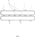
- the subject-matter of the invention is a flat tube 1 (further referred to as "tube") for the flow of the first fluid therein in a heat exchanger.
- the heat exchanger may be of any type (e.g. WCAC and other) as long as it is provided with so-called folded tubes.
- Such tube 1 may be formed by bending a sheet metal strip 2 along the length of the strip 2.
- the sheet of metal may be for example, aluminum.
- the tube 1 may comprise an outside surface and a layer of braze metal 3 thereon.
- the braze material 3 may be, for example, a flux.
- the flux is a chemical compound applied to the joint surfaces before brazing. Its use, with a few exceptions, is crucial in the atmospheric brazing process.
- the braze material 3 may thus be pre-applied on the corresponding surface of said strip 2 to enhance the quality of the brazing joint.
- the tube 1 may further comprise a first main wall 4, a second main wall 5 which is substantially parallel with respect to the first main wall 4.
- the main walls 4, 5 may be substantially flat.
- the terms "substantially parallel” and “substantially flat” should be understood as allowing some deviances from ideal. It is desired that the walls are perfectly parallel or perfectly flat, yet one must take into account that during the production process or during the operational mode of the heat exchanger some deviations may occur.
- the tube 1 may further comprise two complementary side wall portions 6 joining said main walls 4, 5 together so as to define a closed profile of the tube 1.
- the cross section of the tube may be substantially rectangular, or rectangular with rounded corners, yet side wall portions 6 being substantially arcuate in shape having a desired radius of curvature are also envisaged.
- Other shapes of the tube 1 may be used without departing from the scope of the present invention.
- the first main wall 4 and/or the second main wall 5 may further comprise at least one deflector 100.
- the main walls 4, 5 forming the terminal walls of the stack are free of any deflectors 100 and the neighboring walls of the adjacent tubes 1 comprise such deflectors, as the second fluid circuit may be formed between the adjacent tubes 1.
- the tubes 1 are arranged so that the main walls 4,5 of subsequent tube 1 are substantially parallel to the main walls 4,5 of the preceding tube 1.
- Each deflector 100 may be integral with the main wall 4,5 from which it is formed from. In other words, the deflectors 100 are formed directly on the surface of the tube, in particular on the surface of the main wall 4, 5.
- the deflectors 100 may be thus formed by stamping. Preferably, the stamping process is performed way before the metal strip 2 forming the tube 1 is folded to close the profile of said tube. This allows easy production process of the deflectors 100 without a need to create separate sub-components as traditional turbulators. It is to be noted however, that the deflectors 100 protrude outwardly form the closed profile of the tube 1. In other words, the deflector 100 protrudes from the outer face of the tube 1, so that said deflector's outermost portion faces away from the hollow portion of the tube 1. This allows the deflection of the fluid which is not flowing in the tube (first fluid), but to deflect the fluid rinsing the tube 1 (second fluid).
- the flat tube 1 may comprise so-called inner fin located within, yet it has not been shown for the sake of clarity of the drawings.
- the first main wall 4 or the second main wall 5 may comprise at least one deflector 100, as shown in Figs 2-5 .
- the number of the deflectors 100 may increase and should be adapted to provide optimized flow, preferably a turbulent one, to increase the overall efficiency of the heat exchanger, in which the flat tube 1 is intended to be used.
- each of the first main wall 4 and the second main wall 5 may comprise at least one deflector 100.
- Such embodiment refers mainly to the tubes 1 which are intended to be located in the middle of the stack of tubes 1. As the second fluid will rinse both the first main wall 4 and the second main wall 5 of such tube, it is desired that the intended fluid direction of said second fluid is deflected on both sides of the tube 1.
- the flat tube 1 may comprise at least two deflectors 100 on the same main wall 4,5, wherein all deflectors 100 protrude at the same height, the height being measured relatively to the main wall 4, 5 from which said deflectors 100 protrude.
- the outermost portions of each individual deflector 100 is at the same level with respect to the plane formed by the main wall from which said deflector protrudes from.
- the tube 1 may comprise least two deflectors 100 on the same main wall 4,5, wherein at least one deflector 100 comprises a first deflector height 100a, and at least one deflector comprises second deflector height 100b, wherein the first deflector height 100a is different from the second deflector height 100b, the deflector height 100a, 100b being measured relatively to the main wall 4, 5 from which said deflectors 100 protrude.
- the outermost portions of each individual deflector 100 is at the different level with respect to the plane formed by the main wall from which said deflector protrudes from, compared to at least one other deflector 100 protruding from the same main wall 4,5.
- the shape of the deflector 100 should be regarded as non- limiting.
- the deflector 100 may thus have a shape of a dome.
- the deflector 100 may also have a shape of elliptical dome,
- the deflector 100 may also have a shape of bell-shaped dome.
- the deflector 100 may also have a shape of cone with rounded corner.
- the deflector 100 may also have a shape of cube.
- the deflector 100 may also have a shape of cuboid.
- the deflector 100 may also have a shape of pyramid. Other shapes of the deflector 100 are also envisaged.
- Another object of the invention is a heat exchanger 1000 for heat exchange between the first fluid and at least second fluid, comprising at least one flat tube 1 described in previous paragraphs.
- Said heat exchanger may thus comprise a flat tube 1 for the flow therein of a first fluid, wherein the tube 1 may be formed by bending a sheet metal strip 2 along the length of the strip.
- the tube may further comprise a first main wall 4, a second main wall 5 parallel to the first main wall 4, said main walls 4, 5 being substantially flat, two complementary side wall portions 6 joining said main walls together so as to define a closed profile of the tube 1.
- the first main wall 4 and/or the second main wall 5 may further comprise at least one deflector 100, wherein each deflector 100 is integral with the main wall 4,5 from which it is formed from.
- the deflector 100 may protrude outwardly form the closed profile of the tube 1.
- the heat exchanger 1000 may further comprises a pair of headers 1001, 1002 spaced apart from each-other.
- the headers may be fluidly connected with the tubes 1, so that the tubes 1 provide a fluid communication between the headers 1001, 1002.
- the headers 1001, 1002 may comprise plurality of slots to accommodate the flat tubes 1. The shape of said slots must be adapted to the outer perimeter of the tube 1.
- the tubes 1 along with the headers 1001, 1002 may be fluidly connected with each-other.
- a headers- tube assembly is able to provide a first fluid circuit in which the first fluid, i.e. charge air circulates.
- the heat exchanger 1000 may further comprise a housing 1003 with second fluid inlet 1003a and second fluid outlet 1003b.
- the housing 1003 is configured to encapsulate at least the plurality of flat tubes 1 to provide a fluid-tight second fluid circuit.
- the tubes 1 may be arranged in at least one stack of tubes 10, so that the second fluid circuit is provided between the main walls 4,5) of the neighboring flat tubes 1, so that the intended second fluid flow direction is deflected by at least one deflector 100.
- the aforementioned definition of stack of tubes 1 still applies here.
- Conventional heat exchangers comprise tubes interlaced with turbulators which are separate sub-components.
- the conventional turbulator is removed completely and its role is carried out by integrated turbulator 100.
- the integrated turbulators 100 do not require alignment with respect to the tubes before brazing, compared to conventional turbulators.
- At least one deflector 100 of one flat tube 1 is in contact at least with the main wall 4,5 of the other neighboring flat tube 1. As the result, the intended second fluid flow is locally blocked.
- the deflectors 100 of neighboring flat tubes 1 are arranged alternately so that the deflector 100 protruding form first main wall 4 of one flat tube 1 is in contact with the second main wall 5 of the adjacent flat tube 1.
- Such arrangement of the tubes is particularly shown in Figs 2 and 3 .
- the deflectors 100 on adjacent tubes 1 must be so arranged, that they are not in contact with each other. For this reason, the deflector 100 protruding form first main wall 4 of one flat tube 1 fits in the space between the deflectors 100 located on the second main wall 5 of the adjacent flat tube 1, and the deflector 100 protruding form second main wall 5 of one flat tube 1 fits in the space between the deflectors 100 located on the first main wall 4 of adjacent flat tube 1.
- the deflectors 100 may be in contact with each other with the outermost portions of each deflector 100. Naturally, the deflectors having the second height will not be in contact with the deflector 100 of the neighboring tubes 1.
- the second fluid flow may be optimized by the location of the deflectors 100.
- the deflectors 100 may be made in the process of stamping, is way easier to arrange the second fluid flow according to the needs.
- Conventional turbulators would require a complete rearrangement of the process, tools etc.
- he deflectors 100 on the flat tube 1 may be arranged uniformly on the surface of the main wall 4, 5. Uniformly means that the distance between all deflectors 100 is even.
- the deflectors 100 on the flat tube 1 may be arranged non-uniformly on the surface of the main wall 4, 5.
- Non- uniformly means that the distance between one pair of deflectors 100 is different than the distance between the other pair of the deflectors.
- Another object of the invention is a motor vehicle comprising at least one heat exchanger 1000 described above.
Landscapes
- Engineering & Computer Science (AREA)
- Physics & Mathematics (AREA)
- Thermal Sciences (AREA)
- Mechanical Engineering (AREA)
- General Engineering & Computer Science (AREA)
- Geometry (AREA)
- Heat-Exchange Devices With Radiators And Conduit Assemblies (AREA)
Priority Applications (1)
| Application Number | Priority Date | Filing Date | Title |
|---|---|---|---|
| EP23185170.0A EP4491992A1 (fr) | 2023-07-13 | 2023-07-13 | Tube plat |
Applications Claiming Priority (1)
| Application Number | Priority Date | Filing Date | Title |
|---|---|---|---|
| EP23185170.0A EP4491992A1 (fr) | 2023-07-13 | 2023-07-13 | Tube plat |
Publications (1)
| Publication Number | Publication Date |
|---|---|
| EP4491992A1 true EP4491992A1 (fr) | 2025-01-15 |
Family
ID=87280573
Family Applications (1)
| Application Number | Title | Priority Date | Filing Date |
|---|---|---|---|
| EP23185170.0A Withdrawn EP4491992A1 (fr) | 2023-07-13 | 2023-07-13 | Tube plat |
Country Status (1)
| Country | Link |
|---|---|
| EP (1) | EP4491992A1 (fr) |
Citations (5)
| Publication number | Priority date | Publication date | Assignee | Title |
|---|---|---|---|---|
| US3757855A (en) * | 1971-10-15 | 1973-09-11 | Union Carbide Corp | Primary surface heat exchanger |
| WO2009057623A1 (fr) * | 2007-10-31 | 2009-05-07 | Calsonic Kansei Corporation | Echangeur de chaleur |
| US20100044019A1 (en) * | 2008-08-25 | 2010-02-25 | Denso Corporation | Heat exchanger |
| US8235098B2 (en) * | 2008-01-24 | 2012-08-07 | Honeywell International Inc. | Heat exchanger flat tube with oblique elongate dimples |
| US20150308387A1 (en) * | 2012-11-28 | 2015-10-29 | Valeo Termico, S.A. | Gas heat exchanger, in particular for exhaust gases of an engine |
-
2023
- 2023-07-13 EP EP23185170.0A patent/EP4491992A1/fr not_active Withdrawn
Patent Citations (5)
| Publication number | Priority date | Publication date | Assignee | Title |
|---|---|---|---|---|
| US3757855A (en) * | 1971-10-15 | 1973-09-11 | Union Carbide Corp | Primary surface heat exchanger |
| WO2009057623A1 (fr) * | 2007-10-31 | 2009-05-07 | Calsonic Kansei Corporation | Echangeur de chaleur |
| US8235098B2 (en) * | 2008-01-24 | 2012-08-07 | Honeywell International Inc. | Heat exchanger flat tube with oblique elongate dimples |
| US20100044019A1 (en) * | 2008-08-25 | 2010-02-25 | Denso Corporation | Heat exchanger |
| US20150308387A1 (en) * | 2012-11-28 | 2015-10-29 | Valeo Termico, S.A. | Gas heat exchanger, in particular for exhaust gases of an engine |
Similar Documents
| Publication | Publication Date | Title |
|---|---|---|
| US20120103583A1 (en) | Heat exchanger and fin for the same | |
| JPH11294984A (ja) | 並設一体型熱交換器 | |
| EP3907459B1 (fr) | Échangeur de chaleur | |
| CN107314573A (zh) | 一种微通道热交换器 | |
| US20140151006A1 (en) | Connecting Reinforcement For Between The Plates Of A Heat Exchanger | |
| JPH0345300B2 (fr) | ||
| US6364006B1 (en) | Beaded plate for a heat exchanger and method of making same | |
| CN110530190A (zh) | 集管箱及换热器 | |
| JP2007232356A (ja) | 車両用熱交換器 | |
| JPH0245945B2 (fr) | ||
| JPH0571876B2 (fr) | ||
| JP2010121925A (ja) | 熱交換器 | |
| EP4491992A1 (fr) | Tube plat | |
| EP4317899A1 (fr) | Tube pour échangeur de chaleur | |
| JP2009275956A (ja) | 熱交換器 | |
| JP2019090573A (ja) | 熱交換器およびその製造方法 | |
| JPH0345302B2 (fr) | ||
| JP2007127347A (ja) | 熱交換器のタンク構造 | |
| EP3428562A1 (fr) | Échangeur de chaleur comprenant des tubes de fluide ayant une première et une seconde paroi intérieure | |
| JPH11294991A (ja) | 並設一体型熱交換器 | |
| KR200158732Y1 (ko) | 열교환기 | |
| KR20220153825A (ko) | 열교환기 | |
| JPH0345301B2 (fr) | ||
| JP3095540B2 (ja) | 積層型熱交換器 | |
| EP4212811B1 (fr) | Tube plat |
Legal Events
| Date | Code | Title | Description |
|---|---|---|---|
| PUAI | Public reference made under article 153(3) epc to a published international application that has entered the european phase |
Free format text: ORIGINAL CODE: 0009012 |
|
| STAA | Information on the status of an ep patent application or granted ep patent |
Free format text: STATUS: THE APPLICATION HAS BEEN PUBLISHED |
|
| AK | Designated contracting states |
Kind code of ref document: A1 Designated state(s): AL AT BE BG CH CY CZ DE DK EE ES FI FR GB GR HR HU IE IS IT LI LT LU LV MC ME MK MT NL NO PL PT RO RS SE SI SK SM TR |
|
| STAA | Information on the status of an ep patent application or granted ep patent |
Free format text: STATUS: THE APPLICATION IS DEEMED TO BE WITHDRAWN |
|
| 18D | Application deemed to be withdrawn |
Effective date: 20250716 |