EP4491763A1 - Method for manufacturing hot-dip galvanized steel sheet, and equipment for manufacturing hot-dip galvanized steel sheet - Google Patents
Method for manufacturing hot-dip galvanized steel sheet, and equipment for manufacturing hot-dip galvanized steel sheet Download PDFInfo
- Publication number
- EP4491763A1 EP4491763A1 EP23791480.9A EP23791480A EP4491763A1 EP 4491763 A1 EP4491763 A1 EP 4491763A1 EP 23791480 A EP23791480 A EP 23791480A EP 4491763 A1 EP4491763 A1 EP 4491763A1
- Authority
- EP
- European Patent Office
- Prior art keywords
- steel sheet
- hot
- electrode plate
- plating solution
- manufacturing
- Prior art date
- Legal status (The legal status is an assumption and is not a legal conclusion. Google has not performed a legal analysis and makes no representation as to the accuracy of the status listed.)
- Pending
Links
Images



Classifications
-
- C—CHEMISTRY; METALLURGY
- C23—COATING METALLIC MATERIAL; COATING MATERIAL WITH METALLIC MATERIAL; CHEMICAL SURFACE TREATMENT; DIFFUSION TREATMENT OF METALLIC MATERIAL; COATING BY VACUUM EVAPORATION, BY SPUTTERING, BY ION IMPLANTATION OR BY CHEMICAL VAPOUR DEPOSITION, IN GENERAL; INHIBITING CORROSION OF METALLIC MATERIAL OR INCRUSTATION IN GENERAL
- C23C—COATING METALLIC MATERIAL; COATING MATERIAL WITH METALLIC MATERIAL; SURFACE TREATMENT OF METALLIC MATERIAL BY DIFFUSION INTO THE SURFACE, BY CHEMICAL CONVERSION OR SUBSTITUTION; COATING BY VACUUM EVAPORATION, BY SPUTTERING, BY ION IMPLANTATION OR BY CHEMICAL VAPOUR DEPOSITION, IN GENERAL
- C23C2/00—Hot-dipping or immersion processes for applying the coating material in the molten state without affecting the shape; Apparatus therefor
- C23C2/04—Hot-dipping or immersion processes for applying the coating material in the molten state without affecting the shape; Apparatus therefor characterised by the coating material
- C23C2/06—Zinc or cadmium or alloys based thereon
-
- C—CHEMISTRY; METALLURGY
- C23—COATING METALLIC MATERIAL; COATING MATERIAL WITH METALLIC MATERIAL; CHEMICAL SURFACE TREATMENT; DIFFUSION TREATMENT OF METALLIC MATERIAL; COATING BY VACUUM EVAPORATION, BY SPUTTERING, BY ION IMPLANTATION OR BY CHEMICAL VAPOUR DEPOSITION, IN GENERAL; INHIBITING CORROSION OF METALLIC MATERIAL OR INCRUSTATION IN GENERAL
- C23C—COATING METALLIC MATERIAL; COATING MATERIAL WITH METALLIC MATERIAL; SURFACE TREATMENT OF METALLIC MATERIAL BY DIFFUSION INTO THE SURFACE, BY CHEMICAL CONVERSION OR SUBSTITUTION; COATING BY VACUUM EVAPORATION, BY SPUTTERING, BY ION IMPLANTATION OR BY CHEMICAL VAPOUR DEPOSITION, IN GENERAL
- C23C2/00—Hot-dipping or immersion processes for applying the coating material in the molten state without affecting the shape; Apparatus therefor
- C23C2/02—Pretreatment of the material to be coated, e.g. for coating on selected surface areas
-
- C—CHEMISTRY; METALLURGY
- C22—METALLURGY; FERROUS OR NON-FERROUS ALLOYS; TREATMENT OF ALLOYS OR NON-FERROUS METALS
- C22C—ALLOYS
- C22C38/00—Ferrous alloys, e.g. steel alloys
- C22C38/02—Ferrous alloys, e.g. steel alloys containing silicon
-
- C—CHEMISTRY; METALLURGY
- C22—METALLURGY; FERROUS OR NON-FERROUS ALLOYS; TREATMENT OF ALLOYS OR NON-FERROUS METALS
- C22C—ALLOYS
- C22C38/00—Ferrous alloys, e.g. steel alloys
- C22C38/04—Ferrous alloys, e.g. steel alloys containing manganese
-
- C—CHEMISTRY; METALLURGY
- C23—COATING METALLIC MATERIAL; COATING MATERIAL WITH METALLIC MATERIAL; CHEMICAL SURFACE TREATMENT; DIFFUSION TREATMENT OF METALLIC MATERIAL; COATING BY VACUUM EVAPORATION, BY SPUTTERING, BY ION IMPLANTATION OR BY CHEMICAL VAPOUR DEPOSITION, IN GENERAL; INHIBITING CORROSION OF METALLIC MATERIAL OR INCRUSTATION IN GENERAL
- C23C—COATING METALLIC MATERIAL; COATING MATERIAL WITH METALLIC MATERIAL; SURFACE TREATMENT OF METALLIC MATERIAL BY DIFFUSION INTO THE SURFACE, BY CHEMICAL CONVERSION OR SUBSTITUTION; COATING BY VACUUM EVAPORATION, BY SPUTTERING, BY ION IMPLANTATION OR BY CHEMICAL VAPOUR DEPOSITION, IN GENERAL
- C23C2/00—Hot-dipping or immersion processes for applying the coating material in the molten state without affecting the shape; Apparatus therefor
- C23C2/02—Pretreatment of the material to be coated, e.g. for coating on selected surface areas
- C23C2/022—Pretreatment of the material to be coated, e.g. for coating on selected surface areas by heating
-
- C—CHEMISTRY; METALLURGY
- C23—COATING METALLIC MATERIAL; COATING MATERIAL WITH METALLIC MATERIAL; CHEMICAL SURFACE TREATMENT; DIFFUSION TREATMENT OF METALLIC MATERIAL; COATING BY VACUUM EVAPORATION, BY SPUTTERING, BY ION IMPLANTATION OR BY CHEMICAL VAPOUR DEPOSITION, IN GENERAL; INHIBITING CORROSION OF METALLIC MATERIAL OR INCRUSTATION IN GENERAL
- C23C—COATING METALLIC MATERIAL; COATING MATERIAL WITH METALLIC MATERIAL; SURFACE TREATMENT OF METALLIC MATERIAL BY DIFFUSION INTO THE SURFACE, BY CHEMICAL CONVERSION OR SUBSTITUTION; COATING BY VACUUM EVAPORATION, BY SPUTTERING, BY ION IMPLANTATION OR BY CHEMICAL VAPOUR DEPOSITION, IN GENERAL
- C23C2/00—Hot-dipping or immersion processes for applying the coating material in the molten state without affecting the shape; Apparatus therefor
- C23C2/02—Pretreatment of the material to be coated, e.g. for coating on selected surface areas
- C23C2/026—Deposition of sublayers, e.g. adhesion layers or pre-applied alloying elements or corrosion protection
-
- C—CHEMISTRY; METALLURGY
- C23—COATING METALLIC MATERIAL; COATING MATERIAL WITH METALLIC MATERIAL; CHEMICAL SURFACE TREATMENT; DIFFUSION TREATMENT OF METALLIC MATERIAL; COATING BY VACUUM EVAPORATION, BY SPUTTERING, BY ION IMPLANTATION OR BY CHEMICAL VAPOUR DEPOSITION, IN GENERAL; INHIBITING CORROSION OF METALLIC MATERIAL OR INCRUSTATION IN GENERAL
- C23C—COATING METALLIC MATERIAL; COATING MATERIAL WITH METALLIC MATERIAL; SURFACE TREATMENT OF METALLIC MATERIAL BY DIFFUSION INTO THE SURFACE, BY CHEMICAL CONVERSION OR SUBSTITUTION; COATING BY VACUUM EVAPORATION, BY SPUTTERING, BY ION IMPLANTATION OR BY CHEMICAL VAPOUR DEPOSITION, IN GENERAL
- C23C2/00—Hot-dipping or immersion processes for applying the coating material in the molten state without affecting the shape; Apparatus therefor
- C23C2/04—Hot-dipping or immersion processes for applying the coating material in the molten state without affecting the shape; Apparatus therefor characterised by the coating material
-
- C—CHEMISTRY; METALLURGY
- C23—COATING METALLIC MATERIAL; COATING MATERIAL WITH METALLIC MATERIAL; CHEMICAL SURFACE TREATMENT; DIFFUSION TREATMENT OF METALLIC MATERIAL; COATING BY VACUUM EVAPORATION, BY SPUTTERING, BY ION IMPLANTATION OR BY CHEMICAL VAPOUR DEPOSITION, IN GENERAL; INHIBITING CORROSION OF METALLIC MATERIAL OR INCRUSTATION IN GENERAL
- C23C—COATING METALLIC MATERIAL; COATING MATERIAL WITH METALLIC MATERIAL; SURFACE TREATMENT OF METALLIC MATERIAL BY DIFFUSION INTO THE SURFACE, BY CHEMICAL CONVERSION OR SUBSTITUTION; COATING BY VACUUM EVAPORATION, BY SPUTTERING, BY ION IMPLANTATION OR BY CHEMICAL VAPOUR DEPOSITION, IN GENERAL
- C23C2/00—Hot-dipping or immersion processes for applying the coating material in the molten state without affecting the shape; Apparatus therefor
- C23C2/34—Hot-dipping or immersion processes for applying the coating material in the molten state without affecting the shape; Apparatus therefor characterised by the shape of the material to be treated
- C23C2/36—Elongated material
- C23C2/40—Plates; Strips
-
- C—CHEMISTRY; METALLURGY
- C23—COATING METALLIC MATERIAL; COATING MATERIAL WITH METALLIC MATERIAL; CHEMICAL SURFACE TREATMENT; DIFFUSION TREATMENT OF METALLIC MATERIAL; COATING BY VACUUM EVAPORATION, BY SPUTTERING, BY ION IMPLANTATION OR BY CHEMICAL VAPOUR DEPOSITION, IN GENERAL; INHIBITING CORROSION OF METALLIC MATERIAL OR INCRUSTATION IN GENERAL
- C23C—COATING METALLIC MATERIAL; COATING MATERIAL WITH METALLIC MATERIAL; SURFACE TREATMENT OF METALLIC MATERIAL BY DIFFUSION INTO THE SURFACE, BY CHEMICAL CONVERSION OR SUBSTITUTION; COATING BY VACUUM EVAPORATION, BY SPUTTERING, BY ION IMPLANTATION OR BY CHEMICAL VAPOUR DEPOSITION, IN GENERAL
- C23C28/00—Coating for obtaining at least two superposed coatings either by methods not provided for in a single one of groups C23C2/00 - C23C26/00 or by combinations of methods provided for in subclasses C23C and C25C or C25D
- C23C28/02—Coating for obtaining at least two superposed coatings either by methods not provided for in a single one of groups C23C2/00 - C23C26/00 or by combinations of methods provided for in subclasses C23C and C25C or C25D only coatings only including layers of metallic material
-
- C—CHEMISTRY; METALLURGY
- C23—COATING METALLIC MATERIAL; COATING MATERIAL WITH METALLIC MATERIAL; CHEMICAL SURFACE TREATMENT; DIFFUSION TREATMENT OF METALLIC MATERIAL; COATING BY VACUUM EVAPORATION, BY SPUTTERING, BY ION IMPLANTATION OR BY CHEMICAL VAPOUR DEPOSITION, IN GENERAL; INHIBITING CORROSION OF METALLIC MATERIAL OR INCRUSTATION IN GENERAL
- C23C—COATING METALLIC MATERIAL; COATING MATERIAL WITH METALLIC MATERIAL; SURFACE TREATMENT OF METALLIC MATERIAL BY DIFFUSION INTO THE SURFACE, BY CHEMICAL CONVERSION OR SUBSTITUTION; COATING BY VACUUM EVAPORATION, BY SPUTTERING, BY ION IMPLANTATION OR BY CHEMICAL VAPOUR DEPOSITION, IN GENERAL
- C23C28/00—Coating for obtaining at least two superposed coatings either by methods not provided for in a single one of groups C23C2/00 - C23C26/00 or by combinations of methods provided for in subclasses C23C and C25C or C25D
- C23C28/02—Coating for obtaining at least two superposed coatings either by methods not provided for in a single one of groups C23C2/00 - C23C26/00 or by combinations of methods provided for in subclasses C23C and C25C or C25D only coatings only including layers of metallic material
- C23C28/023—Coating for obtaining at least two superposed coatings either by methods not provided for in a single one of groups C23C2/00 - C23C26/00 or by combinations of methods provided for in subclasses C23C and C25C or C25D only coatings only including layers of metallic material only coatings of metal elements only
- C23C28/025—Coating for obtaining at least two superposed coatings either by methods not provided for in a single one of groups C23C2/00 - C23C26/00 or by combinations of methods provided for in subclasses C23C and C25C or C25D only coatings only including layers of metallic material only coatings of metal elements only with at least one zinc-based layer
-
- C—CHEMISTRY; METALLURGY
- C25—ELECTROLYTIC OR ELECTROPHORETIC PROCESSES; APPARATUS THEREFOR
- C25D—PROCESSES FOR THE ELECTROLYTIC OR ELECTROPHORETIC PRODUCTION OF COATINGS; ELECTROFORMING; APPARATUS THEREFOR
- C25D17/00—Constructional parts, or assemblies thereof, of cells for electrolytic coating
-
- C—CHEMISTRY; METALLURGY
- C25—ELECTROLYTIC OR ELECTROPHORETIC PROCESSES; APPARATUS THEREFOR
- C25D—PROCESSES FOR THE ELECTROLYTIC OR ELECTROPHORETIC PRODUCTION OF COATINGS; ELECTROFORMING; APPARATUS THEREFOR
- C25D21/00—Processes for servicing or operating cells for electrolytic coating
- C25D21/02—Heating or cooling
-
- C—CHEMISTRY; METALLURGY
- C25—ELECTROLYTIC OR ELECTROPHORETIC PROCESSES; APPARATUS THEREFOR
- C25D—PROCESSES FOR THE ELECTROLYTIC OR ELECTROPHORETIC PRODUCTION OF COATINGS; ELECTROFORMING; APPARATUS THEREFOR
- C25D3/00—Electroplating: Baths therefor
- C25D3/02—Electroplating: Baths therefor from solutions
- C25D3/20—Electroplating: Baths therefor from solutions of iron
-
- C—CHEMISTRY; METALLURGY
- C25—ELECTROLYTIC OR ELECTROPHORETIC PROCESSES; APPARATUS THEREFOR
- C25D—PROCESSES FOR THE ELECTROLYTIC OR ELECTROPHORETIC PRODUCTION OF COATINGS; ELECTROFORMING; APPARATUS THEREFOR
- C25D5/00—Electroplating characterised by the process; Pretreatment or after-treatment of workpieces
- C25D5/08—Electroplating with moving electrolyte e.g. jet electroplating
-
- C—CHEMISTRY; METALLURGY
- C25—ELECTROLYTIC OR ELECTROPHORETIC PROCESSES; APPARATUS THEREFOR
- C25D—PROCESSES FOR THE ELECTROLYTIC OR ELECTROPHORETIC PRODUCTION OF COATINGS; ELECTROFORMING; APPARATUS THEREFOR
- C25D5/00—Electroplating characterised by the process; Pretreatment or after-treatment of workpieces
- C25D5/48—After-treatment of electroplated surfaces
- C25D5/50—After-treatment of electroplated surfaces by heat-treatment
-
- C—CHEMISTRY; METALLURGY
- C25—ELECTROLYTIC OR ELECTROPHORETIC PROCESSES; APPARATUS THEREFOR
- C25D—PROCESSES FOR THE ELECTROLYTIC OR ELECTROPHORETIC PRODUCTION OF COATINGS; ELECTROFORMING; APPARATUS THEREFOR
- C25D7/00—Electroplating characterised by the article coated
- C25D7/06—Wires; Strips; Foils
- C25D7/0614—Strips or foils
- C25D7/0621—In horizontal cells
-
- C—CHEMISTRY; METALLURGY
- C25—ELECTROLYTIC OR ELECTROPHORETIC PROCESSES; APPARATUS THEREFOR
- C25D—PROCESSES FOR THE ELECTROLYTIC OR ELECTROPHORETIC PRODUCTION OF COATINGS; ELECTROFORMING; APPARATUS THEREFOR
- C25D7/00—Electroplating characterised by the article coated
- C25D7/06—Wires; Strips; Foils
- C25D7/0614—Strips or foils
- C25D7/0642—Anodes
-
- C—CHEMISTRY; METALLURGY
- C25—ELECTROLYTIC OR ELECTROPHORETIC PROCESSES; APPARATUS THEREFOR
- C25D—PROCESSES FOR THE ELECTROLYTIC OR ELECTROPHORETIC PRODUCTION OF COATINGS; ELECTROFORMING; APPARATUS THEREFOR
- C25D7/00—Electroplating characterised by the article coated
- C25D7/06—Wires; Strips; Foils
- C25D7/0614—Strips or foils
- C25D7/0685—Spraying of electrolyte
-
- C—CHEMISTRY; METALLURGY
- C23—COATING METALLIC MATERIAL; COATING MATERIAL WITH METALLIC MATERIAL; CHEMICAL SURFACE TREATMENT; DIFFUSION TREATMENT OF METALLIC MATERIAL; COATING BY VACUUM EVAPORATION, BY SPUTTERING, BY ION IMPLANTATION OR BY CHEMICAL VAPOUR DEPOSITION, IN GENERAL; INHIBITING CORROSION OF METALLIC MATERIAL OR INCRUSTATION IN GENERAL
- C23C—COATING METALLIC MATERIAL; COATING MATERIAL WITH METALLIC MATERIAL; SURFACE TREATMENT OF METALLIC MATERIAL BY DIFFUSION INTO THE SURFACE, BY CHEMICAL CONVERSION OR SUBSTITUTION; COATING BY VACUUM EVAPORATION, BY SPUTTERING, BY ION IMPLANTATION OR BY CHEMICAL VAPOUR DEPOSITION, IN GENERAL
- C23C2/00—Hot-dipping or immersion processes for applying the coating material in the molten state without affecting the shape; Apparatus therefor
- C23C2/02—Pretreatment of the material to be coated, e.g. for coating on selected surface areas
- C23C2/022—Pretreatment of the material to be coated, e.g. for coating on selected surface areas by heating
- C23C2/0224—Two or more thermal pretreatments
Definitions
- This disclosure relates to a method for manufacturing a hot-dip galvanized steel sheet, in particular, a hot-dip galvanized steel sheet using a high tensile strength steel sheet as the base metal, and equipment for manufacturing a hot-dip galvanized steel sheet.
- high tensile strength steel sheets which are available for more lightweight structures and the like are increasing in the fields of automobiles, household appliances, building products, etc.
- Known high tensile strength steel materials include, for example, steel sheets with good hole expansion formability due to the presence of Si in the steel, and steel sheets with improved ductility due to the presence of Si, Al, and Mn to ensure retained austenite ( ⁇ ).
- the hot-dip galvanized steel sheet is manufactured by subjecting a steel sheet as the base metal to heat-annealing at a temperature of about 600 °C to 900 °C in a reducing atmosphere or a non-oxidizing atmosphere and then applying hot-dip galvanizing treatment to the steel sheet. Furthermore, the galvannealed steel sheet is manufactured by heat-alloying the galvanized coating after the above hot-dip galvanizing treatment.
- Si and Mn in the steel are oxidizable elements, and are selectively oxidized in a generally used reducing atmosphere or non-oxidizing atmosphere and concentrated at the surface of the steel sheet to form an oxide.
- This oxide reduces wettability with molten zinc during the coating treatment, resulting in a non-coating state in which coating is not applied. Therefore, with an increase of the Si and Mn concentrations in the steel, the wettability rapidly decreases, and non-coating frequently occurs. Even in the case where non-coating does not occur, there is still a problem of poor coating adhesion. Besides, if Si and Mn in the steel are selectively oxidized and concentrated at the surface of the steel sheet, a significant alloying delay arises in the alloying process after the hot-dip galvanizing, leading to considerably lower productivity.
- WO2013/100615A1 discloses a method with low manufacturing cost to prevent non-coating phenomenon and ensure excellent coating surface quality and coating adhesion as well as high strength, by applying 0.2 g/m 2 to 2 g/m 2 of Fe plating on the base steel sheet and then adjusting heat treatment in a direct fired furnace (DFF) and a radiant tube furnace (RTF) to the predetermined conditions to diffuse Si, Mn, or Al, which are difficult-to-coat elements contained in steel, on the surface to suppress oxide formation.
- DFF direct fired furnace
- RTF radiant tube furnace
- JP2008-231493A discloses a method for manufacturing a hot-dip galvanized steel sheet with excellent spot weldability, by applying 3 g/m 2 or more of Fe plating on the base steel sheet after setting a predetermined grain boundary oxidation depth on the surface of the base steel sheet in the hot rolling process, and then applying galvannealing treatment.
- JP2005-272999A discloses jetting a plating solution to a place between a steel sheet and an electrode through a plurality of through-holes provided on the electrode, and discharging the plating solution through the through-holes of the electrode.
- PTL 1 describes no specific equipment configuration of the Fe plating process.
- a general horizontal electroplating cell or vertical plating cell for example, for a high strength steel sheet with a tensile strength of 590 MPa or more
- the steel sheet shape after cold rolling is poor, and if the steel sheet is passed through the electroplating process as is, contact trouble with the electrode will occur.
- the distance between the electrode and the steel sheet fluctuates, and the Fe plating thickness, which is aimed at the plating amount of 0.2 g/m 2 to 2.0 g/m 2 described in PTL 1, will greatly vary.
- surface concentration of Si and Mn partially occurs during the subsequent annealing process, resulting in non-coating defects and pick-up defects, making stable manufacturing impossible.
- This disclosure was made in view of the above-mentioned problems, and it could be helpful to propose a method to enable manufacturing of a steel sheet having a beautiful coated layer without quality defects such as non-coating or pick-up caused especially by shape disorder of the steel sheet, when applying hot-dip galvanizing or applying hot-dip galvanizing followed even by alloying treatment to a steel sheet containing oxidizable elements, such as Si and Mn, in particular, a high tensile strength steel sheet.
- a hot-dip galvanized steel sheet of this disclosure it is possible to manufacture a steel sheet having a beautiful hot-dip coating layer without quality defects such as non-coating or pick-up, even when applying hot-dip galvanizing to, for example, a high tensile strength steel sheet, which are prone to shape disorder.
- the method for manufacturing a hot-dip galvanized steel sheet of this disclosure is a method for manufacturing a hot-dip galvanized steel sheet through: an electroplating step of, in a gap between a continuously running steel sheet and an electrode plate placed along and opposite the steel sheet, forming Fe-based plating on the surface of the steel sheet through electroplating, by passing current using the electrode plate as an anode and the steel sheet as a cathode while supplying an Fe-based plating solution toward the steel sheet; an annealing step of subjecting the steel sheet after the electroplating step to heat treatment; and a hot dip coating step of applying hot-dip galvanizing to the steel sheet after the annealing step.
- a plating solution discharge rate which is the ratio of the flow rate of the plating solution flowing out to the back side that is not facing the steel sheet of the electrode plate, to the flow rate of the plating solution supplied to the steel sheet, is less than 50 %.
- FIG. 1 is continuous hot-dip galvanized steel sheet manufacturing equipment that includes an electroplating device, which performs an electroplating step, in line.
- the continuous hot-dip galvanized steel sheet manufacturing equipment includes, in order from upstream of the running line of a steel sheet P, for example, a high tension strength steel strip, a payoff reel 51, a coil joining device 52, an entry-side looper 53, a degreasing device 54, an acid cleaning device 55, an electroplating device 56, a water washing device 57, an annealing device 58, a hot-dip galvanizing device 59, an alloying treatment device 60 (used when an alloyed galvanized steel sheet is manufactured), a temper rolling device 61, a post-treatment device 62, a delivery-side looper 63, and an inspection device 64.
- a high tension strength steel strip for example, a high tension strength steel strip, a payoff reel 51, a coil joining device 52, an entry-side looper 53, a degreasing device 54, an acid cleaning device 55, an electroplating device 56, a water washing device 57, an annealing device 58, a hot
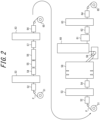
- FIG. 2 illustrates another embodiment in which the electroplating device is on a separate line from the hot-dip galvanizing device. That is, Fe plating is applied on a device line including the payoff reel 51, the coil joining device 52, the entry-side looper 53, the degreasing device 54, the acid cleaning device 55, the electroplating device 56, the water washing device 57, the delivery-side looper 63, and the inspection device 64.
- galvanizing treatment is applied on a normal continuous hot-dip galvanizing line including the payoff reel 51, the coil joining device 52, the entry-side looper 53, the degreasing device 54, the annealing device 58, the hot-dip galvanizing device 59, the alloying treatment device 60, the temper rolling device 61, the post-treatment device 62, the delivery-side looper 63, and the inspection device 64.
- the heating zones of the annealing devices in the former continuous hot-dip galvanized steel sheet manufacturing equipment ( FIG. 1 ) and the latter continuous hot-dip galvanized steel sheet manufacturing equipment ( FIG. 2 ) may be any type of a direct fired furnace (DFF) + a radiant tube furnace (RTF), an IH heating furnace (IHF) + a radiant tube furnace, and a full area radiant tube furnace.
- DFF direct fired furnace
- RTF radiant tube furnace
- IHF IH heating furnace
- the continuous hot-dip galvanized steel sheet manufacturing equipment ( FIG. 1 ) is characterized by its extremely high production efficiency, as it can complete the process to hot-dip galvanizing treatment on a single line.
- the continuous hot-dip galvanized steel sheet manufacturing equipment ( FIG. 2 ) has a little less production efficiency than the continuous hot-dip galvanized steel sheet manufacturing equipment ( FIG. 1 ), as it requires two manufacturing lines.
- an Fe electroplating device can be used for a plurality of normal hot-dip galvanizing lines that do not have an Fe plating device, and the Fe plating device has thus high production efficiency by itself, having an advantage of minimal initial investment.
- the weight of Fe plating formed in the above electroplating device 56 is desirably 2.0 g/m 2 or more, depending on the additive elements in the steel and the length of the annealing device.
- the Fe plating weight is set to 2.0 g/m 2 or more to prevent non-coating defects and pick-up defects from occurring.
- no particular upper limit is placed on the Fe plating weight.
- the Fe plating weight is preferably 8.0 g/m 2 , because the running cost becomes excessively high if the Fe plating weight exceeds 8.0 g/m 2 .
- Fe electroplating has no special restrictions on its chemical system as long as it is Fe-based plating.
- the system may be pure Fe, Fe-B, Fe-C, Fe-P, Fe-N, or Fe-O, but the pure Fe system is particularly preferred.
- the plating bath composition of the pure Fe system can be exemplified as pure Fe: iron component of 55 g/L to 65 g/L and sodium of 5 g/L to 7 g/L, and pH of 2.0 to 2.2.
- the Fe electroplating bath can contain Fe ions, as well as at least one element selected from the group consisting of B, C, P, N, O, Ni, Mn, Mo, Zn, W, Pb, Sn, Cr, V, and Co.
- the total content of these elements in the Fe electroplating bath is preferably set such that the total content of these elements in the Fe electroplating layer is 10 mass% or less.
- FIG. 3 illustrates a horizontal electroplating device used in one of the embodiments.
- the steel sheet P is horizontally run on the running line, and a pair of electrode plates 10 are placed along and opposite the continuously running steel sheet P.
- the electrode plates 10 are preferably insoluble.
- a conductor roller 20 and a backup roller 21 for energizing the steel sheet P are placed at each of the upstream side and the downstream side of the electrode plates 10 in the running direction of the steel sheet P.
- the nozzle header 14 has a plurality of circular tube nozzles 15 formed of insulating material, which extend from the back plate 12 side to the electrode plate 10 side through a plurality of through-holes 10a (see FIG. 4 ) provided on each of the electrode plate 10 and the back plate 12 and stay within the through-holes 10a in the electrode plate 10.
- the reason why it is preferable to form the circular tube nozzles 15 of insulating material is that forming the entire plating solution supply system of insulating material is effective to avoid unintended electrodeposition in the plating solution flow path and to avoid component damage due to sparks between the circular tube nozzles 15 and the electrode plate 10.
- the circular tube nozzles 15 are preferably placed so that their axes are perpendicular to the surface of the steel sheet P.
- the plating solution 30 is supplied from the nozzle header 14 to the circular tube nozzles 15 and is injected from jet orifices at the tips of the circular tube nozzles 15 toward the steel sheet P.
- the plating solution 30 is supplied toward the steel sheet P in the gap between the steel sheet P and the electrode plate 10, and using the electrode plate 10 as an anode and the steel sheet P as a cathode, current is passed between the plated surface of the steel sheet P and the electrode plate 10 to apply electroplating to the steel sheet.
- FIG. 4 illustrates an enlarged view of one nozzle header 14 and its surroundings in the above electroplating device 56.
- the tips of the circular tube nozzles 15 are long enough to stay within the through-holes 10a so that they do not protrude to the steel sheet P side beyond the surface at the steel sheet P side of the electrode plate 10. Furthermore, to prevent the plating solution 30 from flowing out of the through-holes 10a to the back side of the electrode plate 10, it is necessary to cover the space formed between the electrode plate 10 and the back plate 12 due to the interposition of the electrode connecting portion 11 with an insulating body 13 made of, for example, resin.
- the space formed between the electrode plate 10 and the back plate 12 needs to be filled with the insulating body 13.
- the gaps are preferably filled with the insulating body 13.
- the connecting surface between the back plate 12 and the electrode connecting portion 11 is smoothly processed, and then the back plate 12 and the electrode connecting portion 11 are fastened with bolts (not illustrated).
- This structure with the interposition of the electrode connecting portion 11 is extremely effective in assembling this device. That is, it is structurally possible to fasten the back plate 12 and electrode plate 10 without providing the electrode connecting portion 11, but the back plate 12 and electrode plate 10 will adhere to one another only around the fastening bolts. In this case, if a slight gap is generated at a position slightly away from the fastening bolts, a spark will occur during energization at the position of the gap, damaging the back plate 12 and the electrode plate 10. Therefore, such a structure without interposition of the electrode connecting portion 11 is undesirable.
- filling the gap between the back plate 12 and the electrode plate 10 with the insulating body 13 can avoid non-uniform energization between the back plate 12 and the electrode plate 10.
- the member that fills the gap between the back plate 12 and the electrode plate 10 is not an insulating body, energization points other than the electrode connecting portion 11 are created, resulting in non-uniform current distribution when the electrode plate is viewed from the steel sheet.
- the plating solution 30 does not flow out of the through-holes 10a to the back side of the electrode plate 10.
- the jet flow of the plating solution from the circular tube nozzles 15 is concentrated in the gap between the electrode plates 10, and the plating solution can be applied to the steel sheet P passing through this gap with full jet pressure.
- corrective force is exerted on the steel sheet P from both the top and bottom sides, enabling sheet passage and energization while flattening a poorly shaped steel sheet. Therefore, even if cold rolling material is passed without prior correction, it is not affected by shape disorder during plating as described above.
- uniform plating weight can be achieved across the entire width, and Si and Mn surface concentration can be suppressed with a minimum Fe plating weight.
- the plating solution was injected toward the gap with a distance of 20 mm between the electrode and the steel sheet under conditions that the total flow rate of the plating solution was 2.5 m 3 /min.
- the pressing force applied to the steel sheet as a result of this injection was measured.
- the electrode with discharge holes described in PTL 3 only the positions of impact of the plating solution jet flow from the nozzles were the points where the pressing force acts on the steel sheet, and the total pressing force acting on one side of the steel sheet was 290 N (1.53 N per nozzle).
- the plating solution is discharged only from the entry and exit sides of the steel sheet P of the electrode plate.
- the pressure equivalent to the pressure loss of the plating solution flowing between the electrode plate and the steel sheet was applied to the entire electrode surface (the effective area on which the steel sheet pressing force substantially acts was about 50 % of the electrode plate area).
- the steel sheet pressing force was found to reach 3500 N, more than 12 times higher than that of PTL 3.
- corrective force acts from above and below the steel sheet within the plating cell, enabling sheet passage and energization while flattening a poorly shaped steel sheet.
- a plating solution flow rate Q (m 3 /min) per one side of the electrode plate satisfies the following formula (1). It was found that satisfying this formula (1) resulted in sufficient air bubbles being discharged.
- Q ⁇ 60WLH where W is the width (m) of the steel sheet, L is the length (m) in the longitudinal direction of the electrode plate, and H is the distance (m) between the electrode plate and the steel sheet.
- the distance between the electrode plate and the steel sheet is the shortest distance between the electrode plate and the steel sheet in the direction perpendicular to the running direction of the steel sheet.
- 60WLH represents 60 times the volume of the space between the steel sheet and the electrode plate.
- the plating solution flow rate Q is 60WLH or more, the plating solution existing between the steel sheet and the electrode plate can be replaced within 1 second, thus avoiding a decrease in energization property due to electrolysis gas.
- the ratio Ak/An is preferably 12 or less.
- the targets for Fe electroplating and galvanizing described above are not particularly limited, as long as they are steel sheets.
- Examples of plating targets include steel sheets such as common steel and stainless steel, as well as aluminum sheets. This disclosure is effective when applied to steel sheets and is particularly advantageous when applied to high tensile strength steel sheets.
- steel sheets having the following chemical composition are suitable as high tensile strength steel sheets. In the following chemical composition, “%” denotes “mass%” unless otherwise specified.
- the C content is thus preferably 0.025 % or more.
- the C content is thus preferably 0.300 % or less.
- Si is an effective element for strengthening steel to obtain good material properties.
- Si is added to a high tensile strength steel sheet in an amount of 0.2 % or more.
- an expensive alloying element is required to obtain high strength.
- the Si content exceeds 2.5 %, oxide coating formation in oxidation treatment is inhibited.
- a Si content exceeding 2.5 % raises the alloying temperature, making it difficult to obtain desired mechanical properties. Therefore, the Si content is preferably 2.5 % or less.
- Mn is an effective element for increasing the strength of steel.
- the Mn content is preferably 1.5 % or more.
- a Mn content exceeding 3.5 % may make it difficult to ensure weldability, plating adhesion, and strength-ductility balance. Therefore, the Mn content is preferably 1.5 % or more, and the Mn content is preferably 3.5 % or less.
- Al is added for the purpose of deoxidation of the molten steel.
- the Al content is less than 0.001 %, the purpose is not achieved.
- the Al content exceeds 1.000 %, Al forms oxides on the surface, deteriorating the plating appearance (surface appearance). Therefore, the Al content may be 0.001 % or more.
- the Al content may be 1.000 % or less.
- P is one of the inevitably contained elements. Decreasing the P content to less than 0.005 % would increase costs. The P content is thus desirably 0.005 % or more. On the other hand, an increase in the P content deteriorates slab manufacturability. Furthermore, the presence of P inhibits alloying reactions and causes uneven plating. To inhibit these, the P content needs to be decreased to 0.10 % or less. Therefore, the P content may be 0.10 % or less. The P content is preferably 0.05 % or less.
- the S content may be 0.01 % or less.
- the balance is Fe and inevitable impurities.
- the steel sheet may contain one or more elements selected from B: 0.001 % to 0.005 %, Nb: 0.005 % to 0.050 %, Ti: 0.005 % to 0.080 %, Cr: 0.001 % to 1.000 %, Mo: 0.05 % to 1.00 %, Cu: 0.05 % to 1.00 %, Ni: 0.05 % to 1.00 %, and Sb: 0.001 % to 0.200 %, as necessary.
- B can obtain a quenching-promoting effect with a content of 0.001 % or more.
- a B content exceeding 0.005 % deteriorates chemical convertibility. Therefore, when B is contained, the B content may be 0.001 % or more and 0.005 % or less.
- Nb can obtain a strength adjustment (strength improvement) effect with a content of 0.005 % or more.
- a Nb content exceeding 0.05 % increases costs. Therefore, when Nb is contained, the Nb content may be 0.005 % or more and 0.05 % or less.
- Ti can obtain a strength adjustment (strength improvement) effect with a content of 0.005 % or more.
- a Ti content exceeding 0.080 % leads to deterioration of chemical convertibility. Therefore, when Ti is contained, the Ti content may be 0.005 % or more and 0.080 % or less.
- Cr can obtain a quench hardenability effect with a content of 0.001 % or more.
- the Cr content exceeds 1.000 %, Cr concentrates on the surface, resulting in deterioration of weldability. Therefore, when Cr is contained, the Cr content may be 0.001 % or more and 1.000 % or less.
- Mo can obtain a strength adjustment (strength improvement) effect with a content of 0.05 % or more.
- a Mo content exceeding 1.00 % increases costs. Therefore, when Mo is contained, the Mo content may be 0.05 % or more and 1.00 % or less.
- Cu can obtain a retained austenite ( ⁇ ) phase formation promoting effect with a content of 0.05 % or more.
- a Cu content exceeding 1.00 % increases costs. Therefore, when Cu is contained, the Cu content may be 0.05 % or more and 1.00 % or less.
- Ni 0.05 % to 1.00 %
- Ni can obtain a retained austenite ( ⁇ ) phase formation promoting effect with a content of 0.05 % or more.
- a Ni content exceeding 1.00 % increases costs. Therefore, when Ni is contained, the Ni content may be 0.05 % or more and 1.00 % or less.
- Sb can be contained from the viewpoint of suppressing nitriding and oxidation on the steel sheet surface, or decarburization in the tens of microns region of the steel sheet surface caused by oxidation. Suppression of nitriding and oxidation prevents the amount of martensite to be generated on the steel sheet surface from decreasing and improves fatigue resistance and surface quality. These effects are obtained when the Sb content is 0.001 % or more. On the other hand, an Sb content exceeding 0.200 % deteriorates toughness. Therefore, when Sb is contained, the Sb content may be 0.001 % or more and 0.200 % or less.
- An example of this disclosure is a case using hot-dip galvanized steel sheet manufacturing equipment with the configuration illustrated in FIG. 1 or FIG. 2 and using the electroplating device (one cell) illustrated in FIG. 3 in such manufacturing equipment. That is, two plating cells were connected to constitute an electroplating device, which has a longitudinal electrode length of 2 m in one cell.
- a form without Fe plating a form of a general horizontal flow cell ( FIG. 5 ), and a form of a horizontal porous plating cell with plating solution discharge holes (in accordance with the description in FIG. 1 of PTL 3) were used.
- the horizontal flow cell type Fe electroplating device illustrated in FIG. 5 has a passage 43 divided by electrode plates 42a and 42b, between two pairs of rollers of conduit rolls 40 and backup rolls 41.
- the plating solution 30 is supplied from nozzle headers 44 along the passage 43 between the steel sheet P and the electrode plates 42a and 42b, and using the electrode plates 42a and 42b as anodes and the steel sheet P as a cathode, current is passed between the surface of the steel sheet P and the electrode plates 42a and 42b, thus applying Fe electroplating to the steel sheet P.
- the shape of the steel sheet before passing through the electroplating device was measured using a laser type shape measuring device installed upstream from the first plating cell of the electroplating device and then quantified as the magnitude of warpage based on the definition in FIG. 6 .
- FIG. 6 which is a forward view of the steel sheet P in the running direction
- a portion Pb higher than a placed portion Pa is formed in the width direction of the steel sheet P.
- the difference in height between the highest portion Pb and the lowest placed portion Pa was measured as the magnitude of warpage.
- the above Fe plating bath was a sulfuric acid bath, and its composition was adjusted such that an iron component was 55 g/L to 65 g/L, sodium was 5 g/L to 7 g/L, and the pH is 2.0 to 2.2.
- Other plating conditions are presented in Table 2.
- the iron plating weight was measured on each steel sheet after Fe electroplating treatment. The iron plating weight was measured continuously at five points in the width direction of the steel sheet by an on-line coating or plating weight meter using fluorescent X-rays based on a calibration curve prepared in advance, and the variation in plating weight was evaluated.
- the above hot-dip galvanizing was performed in the usual way, with an Al concentration of 0.13 % for galvannealing (GA) baths and an Al concentration of 0.20 % for galvanizing (GI) baths (the balance in both is zinc).
- the galvanizing weight was measured on each steel sheet after hot-dip galvanizing.
- the galvanizing weight was also measured at three points in the width direction of the steel sheet by an on-line coating or plating weight meter using fluorescent X-rays based on a calibration curve prepared in advance and averaged.
- the coating and plating appearance after hot-dip galvanizing was also evaluated.
- the coating and plating appearance score was 1 point if non-coating, severe uneven color tone, or ripple defects constantly occur, 2 points if non-coating, uneven color tone, or ripple defects occur and most of them need to be removed, 3 points if uneven color tone or ripple defects occur and partial removal is necessary, 4 points if no removal is necessary but very mild uneven color tone or poor appearance occurs, and 5 points if no non-coating, uneven color tone, or ripple defects occur.
- the plating solution discharge rate to the back of the electrode plate was determined from the discharge flow rate of the plating solution from plating solution discharge ports 19 (see FIG. 3 ) located at both ends in the longitudinal direction of the top electrode plate and the total flow rate of the plating solution supplied to the gap between the top electrode plate and the steel sheet P.
- each of the hot-dip galvanized steel sheets obtained according to this disclosure has a sound galvanized layer despite the shape disorder before electroplating.
- the horizontal flow cell type Fe electroplating device illustrated in FIG. 5 could not increase the pressing force applied to the steel sheet because the plating solution 30 is supplied from the nozzle headers 44 toward the passage 43. Therefore, under conditions 1 and 2, the corrective force on the steel sheet was weak in the plating cell, and excellent coating and plating appearance could not be obtained. That is, by following this disclosure, coating and plating without being affected by shape disorder of the pre-plated steel sheet are realized. In other words, the results presented in Table 2 indicate that the correction of the steel sheet shape during electroplating by this disclosure is sufficient.
Landscapes
- Chemical & Material Sciences (AREA)
- Engineering & Computer Science (AREA)
- Materials Engineering (AREA)
- Metallurgy (AREA)
- Organic Chemistry (AREA)
- Chemical Kinetics & Catalysis (AREA)
- Mechanical Engineering (AREA)
- Electrochemistry (AREA)
- Electroplating Methods And Accessories (AREA)
- Other Surface Treatments For Metallic Materials (AREA)
- Coating With Molten Metal (AREA)
Abstract
Description
- This disclosure relates to a method for manufacturing a hot-dip galvanized steel sheet, in particular, a hot-dip galvanized steel sheet using a high tensile strength steel sheet as the base metal, and equipment for manufacturing a hot-dip galvanized steel sheet.
- In recent years, the demand for high tensile strength steel sheets (high tensile strength steel materials) which are available for more lightweight structures and the like is increasing in the fields of automobiles, household appliances, building products, etc. Known high tensile strength steel materials include, for example, steel sheets with good hole expansion formability due to the presence of Si in the steel, and steel sheets with improved ductility due to the presence of Si, Al, and Mn to ensure retained austenite (γ).
- However, the following problems exist when a hot-dip galvanized steel sheet or a galvannealed steel sheet is manufactured using a high tensile strength steel sheet containing large amounts (in particular, 0.2 mass% or more) of Si or Mn and having a tensile strength of, for example, 590 MPa or more, as the base metal.
- That is, the hot-dip galvanized steel sheet is manufactured by subjecting a steel sheet as the base metal to heat-annealing at a temperature of about 600 °C to 900 °C in a reducing atmosphere or a non-oxidizing atmosphere and then applying hot-dip galvanizing treatment to the steel sheet. Furthermore, the galvannealed steel sheet is manufactured by heat-alloying the galvanized coating after the above hot-dip galvanizing treatment. Here, Si and Mn in the steel are oxidizable elements, and are selectively oxidized in a generally used reducing atmosphere or non-oxidizing atmosphere and concentrated at the surface of the steel sheet to form an oxide. This oxide reduces wettability with molten zinc during the coating treatment, resulting in a non-coating state in which coating is not applied. Therefore, with an increase of the Si and Mn concentrations in the steel, the wettability rapidly decreases, and non-coating frequently occurs. Even in the case where non-coating does not occur, there is still a problem of poor coating adhesion. Besides, if Si and Mn in the steel are selectively oxidized and concentrated at the surface of the steel sheet, a significant alloying delay arises in the alloying process after the hot-dip galvanizing, leading to considerably lower productivity.
- In view of such problems, for example,
WO2013/100615A1 (PTL 1) discloses a method with low manufacturing cost to prevent non-coating phenomenon and ensure excellent coating surface quality and coating adhesion as well as high strength, by applying 0.2 g/m2 to 2 g/m2 of Fe plating on the base steel sheet and then adjusting heat treatment in a direct fired furnace (DFF) and a radiant tube furnace (RTF) to the predetermined conditions to diffuse Si, Mn, or Al, which are difficult-to-coat elements contained in steel, on the surface to suppress oxide formation. - In addition,
JP2008-231493A - Furthermore, as a method for manufacturing an electroplated steel sheet at high current density,
JP2005-272999A -
- PTL 1:
WO2013/100615A1 - PTL 2:
JP2008-231493A - PTL 3:
JP2005-272999A - PTL 1 describes no specific equipment configuration of the Fe plating process. However, when a general horizontal electroplating cell or vertical plating cell is used, for example, for a high strength steel sheet with a tensile strength of 590 MPa or more, the steel sheet shape after cold rolling is poor, and if the steel sheet is passed through the electroplating process as is, contact trouble with the electrode will occur. Even when the above contact does not occur, the distance between the electrode and the steel sheet fluctuates, and the Fe plating thickness, which is aimed at the plating amount of 0.2 g/m2 to 2.0 g/m2 described in PTL 1, will greatly vary. Then, surface concentration of Si and Mn partially occurs during the subsequent annealing process, resulting in non-coating defects and pick-up defects, making stable manufacturing impossible.
- The same is true for the method disclosed in PTL 2. If Fe plating is applied to the extent that partial surface concentration of Si and Mn does not occur in the annealing process, it is found that a plating amount of more than 10 g/m2 is required, which increases the length of equipment and significantly increases costs. A separate correction process or pre-annealing process could be considered to improve the shape of the steel sheet, but this would also significantly increase costs.
- In the plating electrode corresponding to high current density disclosed in PTL 3, it is taken a way to eliminate air bubbles (electrolytic gas) through both of the gap between a hole 9 and a nozzle 8a, and a
plating solution outlet 11, in order to avoid generation of a large amount of electrolytic gas at high current density, which reduces electrolysis efficiency. Air bubbles (electrolytic gas) are thus eliminated, i.e., the gas venting property is improved. On the other hand, improving the gas venting property also means that the jet pressure of the plating solution is less likely to accumulate between the electrode and the steel sheet, making it difficult to achieve uniform plating weight, particularly for a steel sheet with disordered shape, and the improvement is required. - This disclosure was made in view of the above-mentioned problems, and it could be helpful to propose a method to enable manufacturing of a steel sheet having a beautiful coated layer without quality defects such as non-coating or pick-up caused especially by shape disorder of the steel sheet, when applying hot-dip galvanizing or applying hot-dip galvanizing followed even by alloying treatment to a steel sheet containing oxidizable elements, such as Si and Mn, in particular, a high tensile strength steel sheet.
- We thus provide:
- 1. A method for manufacturing a hot-dip galvanized steel sheet through:
- an electroplating step of, in a gap between a continuously running steel sheet and an electrode plate placed along and opposite the steel sheet, forming Fe-based plating on the surface of the steel sheet through electroplating, by passing current using the electrode plate as an anode and the steel sheet as a cathode while supplying an Fe-based plating solution toward the steel sheet;
- an annealing step of subjecting the steel sheet after the electroplating step to heat treatment; and
- a hot dip coating step of applying hot-dip galvanizing to the steel sheet after the annealing step,
- wherein, in the electroplating step, a plating solution discharge rate, which is the ratio of the flow rate of the plating solution flowing out to the back side that is not facing the steel sheet of the electrode plate, to the flow rate of the plating solution supplied to the steel sheet, is less than 50 %.
- 2. The method for manufacturing a hot-dip galvanized steel sheet according to 1. above, wherein the plating weight of the Fe-based plating is 2.0 g/m2 or more.
- 3. The method for manufacturing a hot-dip galvanized steel sheet according to 1. or 2. above, wherein the plating solution discharge rate is 10 % or less.
- 4. The method for manufacturing a hot-dip galvanized steel sheet according to any one of 1. to 3. above, wherein a plating solution flow rate Q (m3/min) per one side of the electrode plate satisfies the following formula (1):

- 5. The method for manufacturing a hot-dip galvanized steel sheet according to any one of 1. to 4. above, wherein the steel sheet has a chemical composition containing (consisting of), in mass%: C: 0.3 % or less; and one or more of Si and Mn in total: 1.0 % to 6.0 %.
- 6. Equipment for manufacturing a hot-dip galvanized steel sheet, comprising:
- an electroplating device that forms Fe-based plating on a steel sheet running continuously on a running line;
- an annealing device that subjects the steel sheet that has passed through the electroplating device to heat treatment; and
- a hot dip coating device that applies hot-dip galvanizing treatment to the steel sheet that has passed through the annealing device,
- wherein the electroplating device includes: an electrode plate placed along and opposite the running line of the steel sheet; and a jet nozzle that supplies an Fe-based plating solution from the electrode plate side toward the running line, the electrode plate is an anode and the steel sheet is a cathode, and a plating solution discharge rate, which is the ratio of the flow rate of the plating solution flowing out to the back side that is not facing the steel sheet of the electrode plate, to the flow rate of the plating solution supplied from the jet nozzle, is less than 50 %.
- 7. The equipment for manufacturing a hot-dip galvanized steel sheet according to 6. above, wherein the electrode plate has at least one through-hole extending in a direction intersecting the running line and penetrating the electrode plate, and the injection nozzle is placed in at least one of the through-hole.
- 8. The equipment for manufacturing a hot-dip galvanized steel sheet according to 6. or 7. above, wherein the electroplating device includes a back plate and a jet flow header on the back side of the electrode plate, in this order from the running line side, a plurality of the jet nozzles extending through the back plate and the electrode plate are coupled to the jet flow header, the back plate is connected to the back of the electrode plate via an electrode connecting portion, and an insulating body is placed in a space between the back plate and the electrode plate due to the interposition of the electrode connecting portion.
- 9. The equipment for manufacturing a hot-dip galvanized steel sheet according to 8. above, wherein the electroplating device includes one or more plating cells in which a plurality of the electrode plates are assembled as an aggregation without gaps on one of the back plate.
- 10. The equipment for manufacturing a hot-dip galvanized steel sheet according to 9. above, wherein, in each of the plating cells, the jet flow header is divided into a plurality of pieces at locations that do not interfere with the electrode connecting portion.
- 11. The equipment for manufacturing a hot-dip galvanized steel sheet according to any one of 8. to 10. above, wherein the jet flow header has a plating solution pipe that supplies a plating solution into the jet flow header, and the ratio Ak/An of the cross-sectional area Ak of the plating solution pipe to the total cross-sectional area An of jet orifices of the jet nozzles coupled to the jet flow header is 2.5 or more.
- 12. The equipment for manufacturing a hot-dip galvanized steel sheet according to any one of 6. to 11. above, wherein the electroplating device and the annealing device are on an identical line.
- 13. The equipment for manufacturing a hot-dip galvanized steel sheet according to any one of 6. to 11. above, wherein the electroplating device and the annealing device are on separate lines one another.
- According to the method for manufacturing a hot-dip galvanized steel sheet of this disclosure, it is possible to manufacture a steel sheet having a beautiful hot-dip coating layer without quality defects such as non-coating or pick-up, even when applying hot-dip galvanizing to, for example, a high tensile strength steel sheet, which are prone to shape disorder.
- In the accompanying drawings:
-
FIG. 1 is a schematic diagram illustrating a configuration of manufacturing equipment of this disclosure including an electroplating device in line; -
FIG. 2 is a schematic diagram illustrating a configuration of manufacturing equipment of this disclosure including the electroplating device on a separate line; -
FIG. 3 is a cross-sectional schematic diagram of the electroplating cell of this disclosure viewed from the side; -
FIG. 4 is an enlarged view of the area around a circular tube nozzle of the electroplating cell of this disclosure; -
FIG. 5 is a schematic diagram of conventional horizontal flow cell equipment; and -
FIG. 6 is a schematic diagram of a steel sheet viewed squarely from the direction of transport. - The following is a specific description of a method for manufacturing a hot-dip galvanized steel sheet of this disclosure, with reference to the drawings.
- The method for manufacturing a hot-dip galvanized steel sheet of this disclosure is a method for manufacturing a hot-dip galvanized steel sheet through: an electroplating step of, in a gap between a continuously running steel sheet and an electrode plate placed along and opposite the steel sheet, forming Fe-based plating on the surface of the steel sheet through electroplating, by passing current using the electrode plate as an anode and the steel sheet as a cathode while supplying an Fe-based plating solution toward the steel sheet; an annealing step of subjecting the steel sheet after the electroplating step to heat treatment; and a hot dip coating step of applying hot-dip galvanizing to the steel sheet after the annealing step. It is characterized in that, in the electroplating step, a plating solution discharge rate, which is the ratio of the flow rate of the plating solution flowing out to the back side that is not facing the steel sheet of the electrode plate, to the flow rate of the plating solution supplied to the steel sheet, is less than 50 %.
- First, it is described one of the disclosed embodiments of equipment for manufacturing a hot-dip galvanized steel sheet, which is used in the method for manufacturing a hot-dip galvanized steel sheet of this disclosure, with reference to
FIG. 1 . The embodiment illustrated inFIG. 1 is continuous hot-dip galvanized steel sheet manufacturing equipment that includes an electroplating device, which performs an electroplating step, in line. Specifically, the continuous hot-dip galvanized steel sheet manufacturing equipment includes, in order from upstream of the running line of a steel sheet P, for example, a high tension strength steel strip, apayoff reel 51, acoil joining device 52, an entry-side looper 53, adegreasing device 54, anacid cleaning device 55, anelectroplating device 56, awater washing device 57, anannealing device 58, a hot-dip galvanizing device 59, an alloying treatment device 60 (used when an alloyed galvanized steel sheet is manufactured), atemper rolling device 61, apost-treatment device 62, a delivery-side looper 63, and aninspection device 64. -
FIG. 2 illustrates another embodiment in which the electroplating device is on a separate line from the hot-dip galvanizing device. That is, Fe plating is applied on a device line including thepayoff reel 51, thecoil joining device 52, the entry-side looper 53, thedegreasing device 54, theacid cleaning device 55, theelectroplating device 56, thewater washing device 57, the delivery-side looper 63, and theinspection device 64. Subsequently, galvanizing treatment is applied on a normal continuous hot-dip galvanizing line including thepayoff reel 51, thecoil joining device 52, the entry-side looper 53, thedegreasing device 54, theannealing device 58, the hot-dip galvanizing device 59, the alloyingtreatment device 60, thetemper rolling device 61, thepost-treatment device 62, the delivery-side looper 63, and theinspection device 64. - The heating zones of the annealing devices in the former continuous hot-dip galvanized steel sheet manufacturing equipment (
FIG. 1 ) and the latter continuous hot-dip galvanized steel sheet manufacturing equipment (FIG. 2 ) may be any type of a direct fired furnace (DFF) + a radiant tube furnace (RTF), an IH heating furnace (IHF) + a radiant tube furnace, and a full area radiant tube furnace. - The continuous hot-dip galvanized steel sheet manufacturing equipment (
FIG. 1 ) is characterized by its extremely high production efficiency, as it can complete the process to hot-dip galvanizing treatment on a single line. On the other hand, the continuous hot-dip galvanized steel sheet manufacturing equipment (FIG. 2 ) has a little less production efficiency than the continuous hot-dip galvanized steel sheet manufacturing equipment (FIG. 1 ), as it requires two manufacturing lines. However, in the continuous hot-dip galvanized steel sheet manufacturing equipment (FIG. 2 ), an Fe electroplating device can be used for a plurality of normal hot-dip galvanizing lines that do not have an Fe plating device, and the Fe plating device has thus high production efficiency by itself, having an advantage of minimal initial investment. - The weight of Fe plating formed in the
above electroplating device 56 is desirably 2.0 g/m2 or more, depending on the additive elements in the steel and the length of the annealing device. When the Fe plating weight is less than 2.0 g/m2, Si and Mn surface concentration during annealing in a general annealing device cannot be avoided. In other words, the Fe plating weight is set to 2.0 g/m2 or more to prevent non-coating defects and pick-up defects from occurring. On the other hand, no particular upper limit is placed on the Fe plating weight. However, the Fe plating weight is preferably 8.0 g/m2, because the running cost becomes excessively high if the Fe plating weight exceeds 8.0 g/m2. - Fe electroplating has no special restrictions on its chemical system as long as it is Fe-based plating. For example, the system may be pure Fe, Fe-B, Fe-C, Fe-P, Fe-N, or Fe-O, but the pure Fe system is particularly preferred. The plating bath composition of the pure Fe system can be exemplified as pure Fe: iron component of 55 g/L to 65 g/L and sodium of 5 g/L to 7 g/L, and pH of 2.0 to 2.2.
- The Fe electroplating bath can contain Fe ions, as well as at least one element selected from the group consisting of B, C, P, N, O, Ni, Mn, Mo, Zn, W, Pb, Sn, Cr, V, and Co. The total content of these elements in the Fe electroplating bath is preferably set such that the total content of these elements in the Fe electroplating layer is 10 mass% or less.
- Next, with reference to
FIGS. 3 and4 , theFe electroplating device 56 of this disclosure will be specifically described. -
FIG. 3 illustrates a horizontal electroplating device used in one of the embodiments. In this electroplating device, the steel sheet P is horizontally run on the running line, and a pair ofelectrode plates 10 are placed along and opposite the continuously running steel sheet P. Theelectrode plates 10 are preferably insoluble. Furthermore, aconductor roller 20 and abackup roller 21 for energizing the steel sheet P are placed at each of the upstream side and the downstream side of theelectrode plates 10 in the running direction of the steel sheet P. - Here, the
conductor roller 20 can be a roller having hard chrome plating with copper or nickel plating with good conductivity used for the base, on the roller periphery. Theelectrode plate 10 is not particularly limited in its material property and thickness. However, titanium coated with iridium oxide is suitable for material thereof, and the thickness is preferably 5 mm to 100 mm. The distance between the steel sheet P and theelectrode plate 10 is also not particularly limited but is preferably in the range of 2 mm to 20 mm. - On the back of each electrode plate 10 (opposite side of the steel sheet P of the electrode plate), a
back plate 12 is placed via anelectrode connecting portion 11. The current output from a rectifier (not illustrated) is fed into theback plate 12 through an energizingrod 16. Anozzle header 14 for supplying aplating solution 30 toward the steel sheet P is placed on the back of theback plate 12. Theback plate 12 is preferably formed as an integral product within one cell for uniform current distribution. On the other hand, theelectrode plate 10 relative to the steel sheet is preferably divided appropriately in the width and longitudinal directions, in consideration of replacement work, etc. - The
nozzle header 14 has a plurality ofcircular tube nozzles 15 formed of insulating material, which extend from theback plate 12 side to theelectrode plate 10 side through a plurality of through-holes 10a (seeFIG. 4 ) provided on each of theelectrode plate 10 and theback plate 12 and stay within the through-holes 10a in theelectrode plate 10. Here, the reason why it is preferable to form thecircular tube nozzles 15 of insulating material is that forming the entire plating solution supply system of insulating material is effective to avoid unintended electrodeposition in the plating solution flow path and to avoid component damage due to sparks between thecircular tube nozzles 15 and theelectrode plate 10. - The
circular tube nozzles 15 are preferably placed so that their axes are perpendicular to the surface of the steel sheet P. Theplating solution 30 is supplied from thenozzle header 14 to thecircular tube nozzles 15 and is injected from jet orifices at the tips of thecircular tube nozzles 15 toward the steel sheet P. - In this way, while the steel sheet P is being horizontally run, the
plating solution 30 is supplied toward the steel sheet P in the gap between the steel sheet P and theelectrode plate 10, and using theelectrode plate 10 as an anode and the steel sheet P as a cathode, current is passed between the plated surface of the steel sheet P and theelectrode plate 10 to apply electroplating to the steel sheet. -
FIG. 4 illustrates an enlarged view of onenozzle header 14 and its surroundings in theabove electroplating device 56. The tips of thecircular tube nozzles 15 are long enough to stay within the through-holes 10a so that they do not protrude to the steel sheet P side beyond the surface at the steel sheet P side of theelectrode plate 10. Furthermore, to prevent theplating solution 30 from flowing out of the through-holes 10a to the back side of theelectrode plate 10, it is necessary to cover the space formed between theelectrode plate 10 and theback plate 12 due to the interposition of theelectrode connecting portion 11 with an insulatingbody 13 made of, for example, resin. - In other words, to prevent plating solution from flowing out from the steel sheet P side to between the
electrode plate 10 and theback plate 12, at least the space formed between theelectrode plate 10 and theback plate 12 needs to be filled with the insulatingbody 13. When there are gaps between the inner wall of the through-hole 10a of theelectrode plate 10 and the outer periphery of thecircular tube nozzle 15, the gaps are preferably filled with the insulatingbody 13. Here, if the above gaps in the through-hole 10a can be completely filled so that there is no liquid leakage at all, there is no need to fill the gap between theelectrode plate 10 and theback plate 12 with the insulatingbody 13. However, it is difficult in terms of technique or cost to completely cover the above gaps with the insulating body in all of the numerous through-holes 10a of theelectrode plate 10. Considering this, it is effective to more easily cover the space formed between theelectrode plate 10 and theback plate 12 with the insulatingbody 13. - To ensure uniform current flow from the
back plate 12 to a number ofelectrode plates 10, it is preferable that the connecting surface between theback plate 12 and theelectrode connecting portion 11 is smoothly processed, and then theback plate 12 and theelectrode connecting portion 11 are fastened with bolts (not illustrated). This structure with the interposition of theelectrode connecting portion 11 is extremely effective in assembling this device. That is, it is structurally possible to fasten theback plate 12 andelectrode plate 10 without providing theelectrode connecting portion 11, but theback plate 12 andelectrode plate 10 will adhere to one another only around the fastening bolts. In this case, if a slight gap is generated at a position slightly away from the fastening bolts, a spark will occur during energization at the position of the gap, damaging theback plate 12 and theelectrode plate 10. Therefore, such a structure without interposition of theelectrode connecting portion 11 is undesirable. - Furthermore, as described above, filling the gap between the
back plate 12 and theelectrode plate 10 with the insulatingbody 13 can avoid non-uniform energization between theback plate 12 and theelectrode plate 10. When the member that fills the gap between theback plate 12 and theelectrode plate 10 is not an insulating body, energization points other than theelectrode connecting portion 11 are created, resulting in non-uniform current distribution when the electrode plate is viewed from the steel sheet. - With the above structure, the
plating solution 30 does not flow out of the through-holes 10a to the back side of theelectrode plate 10. Thus, the jet flow of the plating solution from thecircular tube nozzles 15 is concentrated in the gap between theelectrode plates 10, and the plating solution can be applied to the steel sheet P passing through this gap with full jet pressure. As a result, corrective force is exerted on the steel sheet P from both the top and bottom sides, enabling sheet passage and energization while flattening a poorly shaped steel sheet. Therefore, even if cold rolling material is passed without prior correction, it is not affected by shape disorder during plating as described above. Thus, uniform plating weight can be achieved across the entire width, and Si and Mn surface concentration can be suppressed with a minimum Fe plating weight. - Here, in one electroplating section (3 cells; electrode size per cell: wide of 1.5 m × length in the sheet passing direction of 1 m) illustrated in
FIG. 3 , the pressing force of the plating solution jet flow from the circular tube nozzles onto the steel sheet P was investigated in the case of using an electrode plate with discharge holes described in PTL 3 above and the case of using the electrode plate illustrated inFIG. 4 according to this disclosure. That is, in one electroplating section illustrated inFIG. 3 , a total of 120 (10 in the electrode width direction × 12 in the sheet passing direction) circular tube nozzles with an inner diameter of 8 mmφ were placed on one of the pair of electrode plates. Then, the plating solution was injected toward the gap with a distance of 20 mm between the electrode and the steel sheet under conditions that the total flow rate of the plating solution was 2.5 m3/min. The pressing force applied to the steel sheet as a result of this injection was measured. As a result, in the electrode with discharge holes described in PTL 3, only the positions of impact of the plating solution jet flow from the nozzles were the points where the pressing force acts on the steel sheet, and the total pressing force acting on one side of the steel sheet was 290 N (1.53 N per nozzle). In contrast, in the electrode illustrated inFIG. 4 , the plating solution is discharged only from the entry and exit sides of the steel sheet P of the electrode plate. Thus, the pressure equivalent to the pressure loss of the plating solution flowing between the electrode plate and the steel sheet was applied to the entire electrode surface (the effective area on which the steel sheet pressing force substantially acts was about 50 % of the electrode plate area). As a result, a form of pressing the steel sheet was realized, and the steel sheet pressing force was found to reach 3500 N, more than 12 times higher than that of PTL 3. - Thus, according to this disclosure, corrective force acts from above and below the steel sheet within the plating cell, enabling sheet passage and energization while flattening a poorly shaped steel sheet.
- To obtain the above effects, it is important to keep the above plating solution discharge rate during electroplating less than 50 %. That is, when the plating solution discharge rate is 50 % or more, the plating solution flow rate between the electrode plate and the steel sheet decreases, resulting in a lower steel sheet pressing force. The plating solution discharge rate is preferably 10 % or less. The above plating solution discharge rate of less than 50 % is realized by the above configuration of the
Fe plating device 56, as described above. - On the other hand, for air bubbles (electrolytic gas) generated during plating, it is preferable that a plating solution flow rate Q (m3/min) per one side of the electrode plate satisfies the following formula (1). It was found that satisfying this formula (1) resulted in sufficient air bubbles being discharged.

- That is, 60WLH represents 60 times the volume of the space between the steel sheet and the electrode plate. When the plating solution flow rate Q is 60WLH or more, the plating solution existing between the steel sheet and the electrode plate can be replaced within 1 second, thus avoiding a decrease in energization property due to electrolysis gas.
- In divided one
jet flow header 14, as illustrated inFIG. 4 , the ratio Ak/An of the cross-sectional area Ak of aplating solution pipe 14a that supplies theplating solution 30 to thisjet flow header 14, to the total cross-sectional area An of jet orifices of thecircular tube nozzles 15 provided on thisjet flow header 14 is preferably 2.5 or more. That is, when Ak/An is less than 2.5, the pressure distribution within the jet flow header tends to be non-uniform. As a result, the jetting speed from thecircular tube nozzles 15 may greatly vary, which may cause problems such as uneven plating weight. When Ak/An exceeds 12, the change in cross-sectional area of the flow path from the jet flow header to the circular tube nozzles is large, resulting in a rapidly shrinking tube condition, which increases the pressure loss and requires excessive capacity for the plating solution delivery pump. Therefore, from the perspective of economic efficiency, the ratio Ak/An is preferably 12 or less. - The cross-sectional areas regarding Ak and An described above are each the minimum area of the inner cross section perpendicular to the axial direction of each of the various tubes. In the case of a plurality of plating solution pipes and circular tube nozzles in each
jet flow header 14, the total cross-sectional areas of the respective tubes are Ak and An. Thus, in thejet flow header 14 illustrated inFIG. 4 , Ak is the cross-sectional area of theplating solution pipe 14a, and An is the total cross-sectional area of the cross-sectional areas of jet orifices of threecircular tube nozzles 15. - The targets for Fe electroplating and galvanizing described above are not particularly limited, as long as they are steel sheets. Examples of plating targets include steel sheets such as common steel and stainless steel, as well as aluminum sheets. This disclosure is effective when applied to steel sheets and is particularly advantageous when applied to high tensile strength steel sheets. Incidentally, steel sheets having the following chemical composition are suitable as high tensile strength steel sheets. In the following chemical composition, "%" denotes "mass%" unless otherwise specified.
- C facilitates an improvement in workability as a result of formation of retained austenite layer, martensite phase, or the like as steel microstructure. The C content is thus preferably 0.025 % or more. When the C content exceeds 0.300 %, weldability decreases. The C content is thus preferably 0.300 % or less.
- Si is an effective element for strengthening steel to obtain good material properties. Thus, Si is added to a high tensile strength steel sheet in an amount of 0.2 % or more. When the Si content is less than 0.2 %, an expensive alloying element is required to obtain high strength. When the Si content exceeds 2.5 %, oxide coating formation in oxidation treatment is inhibited. In addition, a Si content exceeding 2.5 % raises the alloying temperature, making it difficult to obtain desired mechanical properties. Therefore, the Si content is preferably 2.5 % or less.
- Mn is an effective element for increasing the strength of steel. To secure a tensile strength of 590 MPa or more, the Mn content is preferably 1.5 % or more. A Mn content exceeding 3.5 % may make it difficult to ensure weldability, plating adhesion, and strength-ductility balance. Therefore, the Mn content is preferably 1.5 % or more, and the Mn content is preferably 3.5 % or less.
- In addition to the above components, the following respective elements can also be contained in the steel sheet.
- Al is added for the purpose of deoxidation of the molten steel. However, when the Al content is less than 0.001 %, the purpose is not achieved. On the other hand, when the Al content exceeds 1.000 %, Al forms oxides on the surface, deteriorating the plating appearance (surface appearance). Therefore, the Al content may be 0.001 % or more. The Al content may be 1.000 % or less.
- P is one of the inevitably contained elements. Decreasing the P content to less than 0.005 % would increase costs. The P content is thus desirably 0.005 % or more. On the other hand, an increase in the P content deteriorates slab manufacturability. Furthermore, the presence of P inhibits alloying reactions and causes uneven plating. To inhibit these, the P content needs to be decreased to 0.10 % or less. Therefore, the P content may be 0.10 % or less. The P content is preferably 0.05 % or less.
- S is an inevitably contained element in the steelmaking process. However, a large amount of S deteriorates weldability. Therefore, the S content may be 0.01 % or less.
- When the steel sheet contains the above components, the balance is Fe and inevitable impurities.
- Furthermore, the steel sheet may contain one or more elements selected from B: 0.001 % to 0.005 %, Nb: 0.005 % to 0.050 %, Ti: 0.005 % to 0.080 %, Cr: 0.001 % to 1.000 %, Mo: 0.05 % to 1.00 %, Cu: 0.05 % to 1.00 %, Ni: 0.05 % to 1.00 %, and Sb: 0.001 % to 0.200 %, as necessary.
- The appropriate contents of these elements when added and the reasons for their limitations are as follows.
- B can obtain a quenching-promoting effect with a content of 0.001 % or more. On the other hand, a B content exceeding 0.005 % deteriorates chemical convertibility. Therefore, when B is contained, the B content may be 0.001 % or more and 0.005 % or less.
- Nb can obtain a strength adjustment (strength improvement) effect with a content of 0.005 % or more. On the other hand, a Nb content exceeding 0.05 % increases costs. Therefore, when Nb is contained, the Nb content may be 0.005 % or more and 0.05 % or less.
- Ti can obtain a strength adjustment (strength improvement) effect with a content of 0.005 % or more. On the other hand, a Ti content exceeding 0.080 % leads to deterioration of chemical convertibility. Therefore, when Ti is contained, the Ti content may be 0.005 % or more and 0.080 % or less.
- Cr can obtain a quench hardenability effect with a content of 0.001 % or more. On the other hand, when the Cr content exceeds 1.000 %, Cr concentrates on the surface, resulting in deterioration of weldability. Therefore, when Cr is contained, the Cr content may be 0.001 % or more and 1.000 % or less.
- Mo can obtain a strength adjustment (strength improvement) effect with a content of 0.05 % or more. On the other hand, a Mo content exceeding 1.00 % increases costs. Therefore, when Mo is contained, the Mo content may be 0.05 % or more and 1.00 % or less.
- Cu can obtain a retained austenite (γ) phase formation promoting effect with a content of 0.05 % or more. On the other hand, a Cu content exceeding 1.00 % increases costs. Therefore, when Cu is contained, the Cu content may be 0.05 % or more and 1.00 % or less.
- Ni can obtain a retained austenite (γ) phase formation promoting effect with a content of 0.05 % or more. On the other hand, a Ni content exceeding 1.00 % increases costs. Therefore, when Ni is contained, the Ni content may be 0.05 % or more and 1.00 % or less.
- Sb can be contained from the viewpoint of suppressing nitriding and oxidation on the steel sheet surface, or decarburization in the tens of microns region of the steel sheet surface caused by oxidation. Suppression of nitriding and oxidation prevents the amount of martensite to be generated on the steel sheet surface from decreasing and improves fatigue resistance and surface quality. These effects are obtained when the Sb content is 0.001 % or more. On the other hand, an Sb content exceeding 0.200 % deteriorates toughness. Therefore, when Sb is contained, the Sb content may be 0.001 % or more and 0.200 % or less.
- In the following, examples of this disclosure are described. The technical scope of this disclosure is not limited to the following examples.
- An example of this disclosure is a case using hot-dip galvanized steel sheet manufacturing equipment with the configuration illustrated in
FIG. 1 orFIG. 2 and using the electroplating device (one cell) illustrated inFIG. 3 in such manufacturing equipment. That is, two plating cells were connected to constitute an electroplating device, which has a longitudinal electrode length of 2 m in one cell. As comparative examples, a form without Fe plating, a form of a general horizontal flow cell (FIG. 5 ), and a form of a horizontal porous plating cell with plating solution discharge holes (in accordance with the description inFIG. 1 of PTL 3) were used. - Here, the horizontal flow cell type Fe electroplating device illustrated in
FIG. 5 has apassage 43 divided byelectrode plates passage 43, theplating solution 30 is supplied fromnozzle headers 44 along thepassage 43 between the steel sheet P and theelectrode plates electrode plates electrode plates - The shape of the steel sheet before passing through the electroplating device was measured using a laser type shape measuring device installed upstream from the first plating cell of the electroplating device and then quantified as the magnitude of warpage based on the definition in
FIG. 6 . Specifically, as illustrated inFIG. 6 , which is a forward view of the steel sheet P in the running direction, if warpage occurs in steel sheet P, when the steel sheet P is placed on a flat plate, a portion Pb higher than a placed portion Pa is formed in the width direction of the steel sheet P. In the steel sheet P before Fe electroplating, the difference in height between the highest portion Pb and the lowest placed portion Pa was measured as the magnitude of warpage. - Using each example of hot-dip galvanized steel sheet manufacturing equipment as described above, a steel sheet with a thickness of 1.4 mm and a width of 1200 mm was run at a sheet passing speed of 1.5 m/s for Fe electroplating and hot-dip galvanizing treatment. The chemical composition of the steel sheet is presented in Table 1.
-
Table 1 (mass%) C Si Mn P S 0.12 0.5 2.5 0.01 0.001 - The above Fe plating bath was a sulfuric acid bath, and its composition was adjusted such that an iron component was 55 g/L to 65 g/L, sodium was 5 g/L to 7 g/L, and the pH is 2.0 to 2.2. Other plating conditions are presented in Table 2. The iron plating weight was measured on each steel sheet after Fe electroplating treatment. The iron plating weight was measured continuously at five points in the width direction of the steel sheet by an on-line coating or plating weight meter using fluorescent X-rays based on a calibration curve prepared in advance, and the variation in plating weight was evaluated.
- The above hot-dip galvanizing was performed in the usual way, with an Al concentration of 0.13 % for galvannealing (GA) baths and an Al concentration of 0.20 % for galvanizing (GI) baths (the balance in both is zinc). The galvanizing weight was measured on each steel sheet after hot-dip galvanizing. The galvanizing weight was also measured at three points in the width direction of the steel sheet by an on-line coating or plating weight meter using fluorescent X-rays based on a calibration curve prepared in advance and averaged.
- Furthermore, the coating and plating appearance after hot-dip galvanizing was also evaluated. The coating and plating appearance score was 1 point if non-coating, severe uneven color tone, or ripple defects constantly occur, 2 points if non-coating, uneven color tone, or ripple defects occur and most of them need to be removed, 3 points if uneven color tone or ripple defects occur and partial removal is necessary, 4 points if no removal is necessary but very mild uneven color tone or poor appearance occurs, and 5 points if no non-coating, uneven color tone, or ripple defects occur.
- The plating solution discharge rate to the back of the electrode plate was determined from the discharge flow rate of the plating solution from plating solution discharge ports 19 (see
FIG. 3 ) located at both ends in the longitudinal direction of the top electrode plate and the total flow rate of the plating solution supplied to the gap between the top electrode plate and the steel sheet P. - The results of the above measurements and evaluations are presented in Table 2 along with the electroplating conditions.
-
Table 2 No Sheet passing speed (m/s) Width W of steel sheet (m) Steel sheet shape before electroplating (mm) Fe plating Galvanizing Coating and plating score Coating and plating appearance Classification Plating cell form Electroplating device arrangement Electrode plate Longitudinal length L (m) Distance H of electrode plate - steel sheet (mm) Discharge rate to back of electrode (%) Plating solution flow rate (m3/min) Right side of Formula (1) Satisfaction! Dissatisfaction of Formula (1) Variation of Fe plating in width direction (g/m2) Galvanizing weight (g/m2) Coated layer 1 1.5 1.2 10 Flow cell ( FIG. 5 )In-line 1.0 30 0 2.5 2.16 Satisfaction 2.1-5.3 44.2 GA 2 Uneven alloy color tone Comparative Example 2 1.5 1.2 10 Flow cell ( FIG. 5 )In-line 1.0 30 0 2.5 2.16 Satisfaction 2.2-5.2 60.4 Gi 1 Ripple defects Comparative Example 3 1.5 1.2 10 Porous and with discharge holes (PTL 3) In-line 1.0 30 50 2.5 2.16 Satisfaction 2.0-5.5 44.1 GA 2 Uneven alloy color tone Comparative Example 4 1.5 1.2 10 Non-porous and no discharge holes ( FIG. 3 )In-line 1.0 30 0 2.5 2.16 Satisfaction 3.0-4.2 44.1 GA 5 No uneven color tone Example 5 1.5 1.2 10 Non-porous and no discharge holes ( FIG. 3 )In-line 1.0 30 5 2.5 2.16 Satisfaction 2.8-4.2 45.2 GA 5 No uneven color tone Example 6 1.5 1.2 10 Non-porous and no discharge holes ( FIG. 3 )In-line 1.0 30 10 2.5 2.16 Satisfaction 2.8-4.3 45.1 GA 5 No uneven color tone Example 7 1.5 1.2 10 Non-porous and no discharge holes ( FIG. 3 )In-line 1.0 30 15 2.5 2.16 Satisfaction 2.6-4.6 44.8 GA 3 Uneven alloy color tone Example 8 1.5 1.2 10 Non-porous and no discharge holes ( FIG. 3 )In-line 1.0 30 0 2.5 2.16 Satisfaction 3.0-4.2 60.1 Gi 5 No ripple defects Example 9 1.5 1.2 10 Non-porous and no discharge holes ( FIG. 3 )In-line 1.0 30 0 2.1 2.16 Dissatisfaction 2.8-4.5 45.0 GA 4 Slight uneven color tone Example 10 1.5 1.2 10 Non-porous and no discharge holes ( FIG. 3 )In-line 1.0 30 0 1.5 2.16 Dissatisfaction 2.0-5.5 45.2 GA 3 Slight uneven color tone Example 11 1.5 1.2 10 Non-porous and no discharge holes ( FIG. 3 )In-line 1.0 20 0 1.5 1.44 Satisfaction 3.1-4.0 45.2 GA 5 No uneven color tone Example 12 1.5 1.2 10 Non-porous and no discharge holes ( FIG. 3 )Separate line 1.0 30 0 2.5 2.16 Satisfaction 3.0-4.2 46.1 GA 5 No uneven color tone Example - As presented in Table 2, each of the hot-dip galvanized steel sheets obtained according to this disclosure has a sound galvanized layer despite the shape disorder before electroplating. On the other hand, the horizontal flow cell type Fe electroplating device illustrated in
FIG. 5 could not increase the pressing force applied to the steel sheet because theplating solution 30 is supplied from thenozzle headers 44 toward thepassage 43. Therefore, under conditions 1 and 2, the corrective force on the steel sheet was weak in the plating cell, and excellent coating and plating appearance could not be obtained. That is, by following this disclosure, coating and plating without being affected by shape disorder of the pre-plated steel sheet are realized. In other words, the results presented in Table 2 indicate that the correction of the steel sheet shape during electroplating by this disclosure is sufficient. -
- P
- steel sheet
- 10
- electrode plate
- 10a
- through-hole
- 11
- electrode connecting portion
- 12
- back plate
- 13
- insulating body
- 14
- jet flow header
- 15
- circular tube nozzle
- 16
- energizing rod
- 20
- conductor roller
- 21
- backup roller
- 30
- plating solution
- 51
- payoff reel
- 52
- joining device
- 53
- entry-side looper
- 54
- degreasing device
- 55
- acid cleaning device
- 56
- Fe electroplating device
- 57
- water washing device
- 58
- annealing device
- 59
- hot-dip galvanizing device
- 60
- alloying treatment device
- 61
- temper rolling device
- 62
- post-treatment device
- 63
- delivery-side looper
- 64
- inspection device
- 65
- tension reel
Claims (13)
- A method for manufacturing a hot-dip galvanized steel sheet through:an electroplating step of, in a gap between a continuously running steel sheet and an electrode plate placed along and opposite the steel sheet, forming Fe-based plating on the surface of the steel sheet through electroplating, by passing current using the electrode plate as an anode and the steel sheet as a cathode while supplying an Fe-based plating solution toward the steel sheet;an annealing step of subjecting the steel sheet after the electroplating step to heat treatment; anda hot dip coating step of applying hot-dip galvanizing to the steel sheet after the annealing step,wherein, in the electroplating step, a plating solution discharge rate, which is the ratio of the flow rate of the plating solution flowing out to the back side that is not facing the steel sheet of the electrode plate, to the flow rate of the plating solution supplied to the steel sheet, is less than 50 %.
- The method for manufacturing a hot-dip galvanized steel sheet according to claim 1, wherein the plating weight of the Fe-based plating is 2.0 g/m2 or more.
- The method for manufacturing a hot-dip galvanized steel sheet according to claim 1 or 2, wherein the plating solution discharge rate is 10 % or less.
- The method for manufacturing a hot-dip galvanized steel sheet according to any one of claims 1 to 3, wherein a plating solution flow rate Q (m3/min) per one side of the electrode plate satisfies the following formula (1):

- The method for manufacturing a hot-dip galvanized steel sheet according to any one of claims 1 to 4, wherein the steel sheet has a chemical composition containing, in mass%: C: 0.3 % or less; and one or more of Si and Mn in total: 1.0 % to 6.0 %.
- Equipment for manufacturing a hot-dip galvanized steel sheet, comprising:an electroplating device that forms Fe-based plating on a steel sheet running continuously on a running line;an annealing device that subjects the steel sheet that has passed through the electroplating device to heat treatment; anda hot dip coating device that applies hot-dip galvanizing treatment to the steel sheet that has passed through the annealing device,wherein the electroplating device includes: an electrode plate placed along and opposite the running line of the steel sheet; and a jet nozzle that supplies an Fe-based plating solution from the electrode plate side toward the running line, the electrode plate is an anode and the steel sheet is a cathode, and a plating solution discharge rate, which is the ratio of the flow rate of the plating solution flowing out to the back side that is not facing the steel sheet of the electrode plate, to the flow rate of the plating solution supplied from the jet nozzle, is less than 50 %.
- The equipment for manufacturing a hot-dip galvanized steel sheet according to claim 6, wherein the electrode plate has at least one through-hole extending in a direction intersecting the running line and penetrating the electrode plate, and the injection nozzle is placed in at least one of the through-hole.
- The equipment for manufacturing a hot-dip galvanized steel sheet according to claim 6 or 7, wherein the electroplating device includes a back plate and a jet flow header on the back side of the electrode plate, in this order from the running line side, a plurality of the jet nozzles extending through the back plate and the electrode plate are coupled to the jet flow header, the back plate is connected to the back of the electrode plate via an electrode connecting portion, and an insulating body is placed in a space between the back plate and the electrode plate due to the interposition of the electrode connecting portion.
- The equipment for manufacturing a hot-dip galvanized steel sheet according to claim 8, wherein the electroplating device includes one or more plating cells in which a plurality of the electrode plates are assembled as an aggregation without gaps on one of the back plate.
- The equipment for manufacturing a hot-dip galvanized steel sheet according to claim 9, wherein, in each of the plating cells, the jet flow header is divided into a plurality of pieces at locations that do not interfere with the electrode connecting portion.
- The equipment for manufacturing a hot-dip galvanized steel sheet according to any one of claims 8 to 10, wherein the jet flow header has a plating solution pipe that supplies a plating solution into the jet flow header, and the ratio Ak/An of the cross-sectional area Ak of the plating solution pipe to the total cross-sectional area An of jet orifices of the jet nozzles coupled to the jet flow header is 2.5 or more.
- The equipment for manufacturing a hot-dip galvanized steel sheet according to any one of claims 6 to 11, wherein the electroplating device and the annealing device are on an identical line.
- The equipment for manufacturing a hot-dip galvanized steel sheet according to any one of claims 6 to 11, wherein the electroplating device and the annealing device are on separate lines one another.
Applications Claiming Priority (2)
| Application Number | Priority Date | Filing Date | Title |
|---|---|---|---|
| JP2022068495A JP7694447B2 (en) | 2022-04-18 | 2022-04-18 | Manufacturing method of hot-dip galvanized steel sheet and manufacturing equipment of hot-dip galvanized steel sheet |
| PCT/JP2023/002757 WO2023203824A1 (en) | 2022-04-18 | 2023-01-27 | Method for manufacturing hot-dip galvanized steel sheet, and equipment for manufacturing hot-dip galvanized steel sheet |
Publications (2)
| Publication Number | Publication Date |
|---|---|
| EP4491763A1 true EP4491763A1 (en) | 2025-01-15 |
| EP4491763A4 EP4491763A4 (en) | 2026-01-07 |
Family
ID=88419526
Family Applications (1)
| Application Number | Title | Priority Date | Filing Date |
|---|---|---|---|
| EP23791480.9A Pending EP4491763A4 (en) | 2022-04-18 | 2023-01-27 | METHOD FOR PRODUCE A HOT-DIP GALVANIZED STEEL SHEET AND DEVICE FOR PRODUCE A HOT-DIP GALVANIZED STEEL SHEET |
Country Status (7)
| Country | Link |
|---|---|
| US (1) | US20250223682A1 (en) |
| EP (1) | EP4491763A4 (en) |
| JP (1) | JP7694447B2 (en) |
| KR (1) | KR20240171127A (en) |
| CN (1) | CN119032198A (en) |
| MX (1) | MX2024012220A (en) |
| WO (1) | WO2023203824A1 (en) |
Family Cites Families (10)
| Publication number | Priority date | Publication date | Assignee | Title |
|---|---|---|---|---|
| JP3243843B2 (en) * | 1992-06-02 | 2002-01-07 | 日本鋼管株式会社 | Strip vibration prevention method in electrolytic processing line |
| JP4299560B2 (en) * | 2003-03-20 | 2009-07-22 | 日新製鋼株式会社 | Method for producing high-strength galvannealed steel sheet with excellent workability |
| JP4586423B2 (en) | 2004-02-27 | 2010-11-24 | Jfeスチール株式会社 | Method for producing electroplated steel sheet |
| JP4791992B2 (en) | 2007-03-20 | 2011-10-12 | 日新製鋼株式会社 | Method for producing alloyed hot-dip galvanized steel sheet for spot welding |
| KR20130076589A (en) | 2011-12-28 | 2013-07-08 | 주식회사 포스코 | High strength galvanized steel sheet having excellent surface property and coating adhesion method for manufacturing the same |
| WO2017213021A1 (en) * | 2016-06-09 | 2017-12-14 | Jfeスチール株式会社 | Method for producing electroplated steel sheet and production device therefor |
| JP7161146B2 (en) | 2019-11-26 | 2022-10-26 | Jfeスチール株式会社 | Zn-Ni alloy plated steel sheet manufacturing method and electroplating equipment |
| US20210215100A1 (en) * | 2020-01-14 | 2021-07-15 | Rolls-Royce North American Technologies Inc. | Blow down impingement start system |
| JP7247946B2 (en) | 2020-04-24 | 2023-03-29 | Jfeスチール株式会社 | Hot-dip galvanized steel sheet and its manufacturing method |
| CN119013441A (en) * | 2022-03-18 | 2024-11-22 | 杰富意钢铁株式会社 | Method for circulating iron-based plating solution, method for producing iron-based plating solution, and method for producing alloyed hot-dip galvanized steel sheet |
-
2022
- 2022-04-18 JP JP2022068495A patent/JP7694447B2/en active Active
-
2023
- 2023-01-27 US US18/848,912 patent/US20250223682A1/en active Pending
- 2023-01-27 KR KR1020247036433A patent/KR20240171127A/en active Pending
- 2023-01-27 EP EP23791480.9A patent/EP4491763A4/en active Pending
- 2023-01-27 WO PCT/JP2023/002757 patent/WO2023203824A1/en not_active Ceased
- 2023-01-27 CN CN202380034287.7A patent/CN119032198A/en active Pending
-
2024
- 2024-10-02 MX MX2024012220A patent/MX2024012220A/en unknown
Also Published As
| Publication number | Publication date |
|---|---|
| JP2023158573A (en) | 2023-10-30 |
| WO2023203824A1 (en) | 2023-10-26 |
| JP7694447B2 (en) | 2025-06-18 |
| EP4491763A4 (en) | 2026-01-07 |
| CN119032198A (en) | 2024-11-26 |
| US20250223682A1 (en) | 2025-07-10 |
| MX2024012220A (en) | 2024-11-08 |
| KR20240171127A (en) | 2024-12-06 |
Similar Documents
| Publication | Publication Date | Title |
|---|---|---|
| US20260042279A1 (en) | Galvannealed steel sheet, chemical-conversion-treated steel sheet, electrodeposition-coated steel sheet, and automotive part | |
| EP2803748B1 (en) | Hot stamp molded article, and method for producing hot stamp molded article | |
| EP3647445B1 (en) | Hot-pressed member and method for manufacturing same, and cold-rolled steel sheet for hot pressing and method for manufacturing same | |
| CN102011053B (en) | High-yield-ratio high-strength thin steel sheet excelling in weldability and ductility and manufacturing method thereof | |
| JP2006265583A (en) | Hot-rolled steel sheet for hot pressing, manufacturing method thereof, and manufacturing method of hot-press formed member | |
| JP3459500B2 (en) | High-strength galvannealed steel sheet excellent in formability and plating adhesion and method for producing the same | |
| JP5888267B2 (en) | Method for producing high-strength hot-dip galvanized steel sheet and high-strength hot-dip galvanized steel sheet | |
| JP5888268B2 (en) | Method for producing high-strength hot-dip galvanized steel sheet and high-strength hot-dip galvanized steel sheet | |
| KR20200131331A (en) | Alloyed hot-dip galvanized steel sheet, and method of manufacturing an alloyed hot-dip galvanized steel sheet | |
| JP7235165B2 (en) | Material cold-rolled steel sheet with Fe-based coating, method for manufacturing cold-rolled steel sheet with Fe-based coating, method for manufacturing cold-rolled steel sheet with Fe-based coating, method for manufacturing hot-dip galvanized steel sheet, and method for manufacturing alloyed hot-dip galvanized steel sheet | |
| EP4242359A1 (en) | Galvanized steel sheet, electrodeposition coated steel sheet, automotive part, method for manufacturing electrodeposition coated steel sheet, and method for manufacturing galvanized steel sheet | |
| EP4600397A1 (en) | Steel plate, resistance spot welding method, resistance spot welding member, and method for manufacturing steel plate | |
| US20250223682A1 (en) | Method for manufacturing hot-dip galvanized steel sheet, and equipment for manufacturing hot-dip galvanized steel sheet | |
| JP4299560B2 (en) | Method for producing high-strength galvannealed steel sheet with excellent workability | |
| JP7247946B2 (en) | Hot-dip galvanized steel sheet and its manufacturing method | |
| JP2022168731A (en) | Hot dip galvanized metal sheet manufacturing method and hot dip galvanized metal sheet manufacturing equipment | |
| JP7673676B2 (en) | Zn-Ni alloy plated steel sheet manufacturing method and manufacturing equipment | |
| JP6787360B2 (en) | Manufacturing method of hot-dip galvanized steel sheet | |
| JP7726419B1 (en) | High-strength hot-dip galvanized steel sheet and method for manufacturing the same | |
| JP3212436B2 (en) | Manufacturing method of structural steel plate | |
| EP3889277A1 (en) | High-strength steel sheet and method for manufacturing same | |
| EP4317516A1 (en) | Fe-based electroplated steel sheet, hot-dip galvanized steel sheet, and methods for manufacturing same | |
| CN116457504B (en) | Manufacturing methods for galvanized steel sheets, electrodeposited coated steel sheets, automotive parts, and galvanized steel sheets. | |
| EP4242356A1 (en) | Zinc alloy-plated steel sheet, electrodeposited steel sheet, motor vehicle component, method for producing electrodeposited steel sheet, and method for producing zinc alloy-plated steel sheet | |
| JPH05132749A (en) | Manufacture of high strength galvannealed steel sheet excellent in uniformity of fil and powdering resistance |
Legal Events
| Date | Code | Title | Description |
|---|---|---|---|
| STAA | Information on the status of an ep patent application or granted ep patent |
Free format text: STATUS: THE INTERNATIONAL PUBLICATION HAS BEEN MADE |
|
| PUAI | Public reference made under article 153(3) epc to a published international application that has entered the european phase |
Free format text: ORIGINAL CODE: 0009012 |
|
| STAA | Information on the status of an ep patent application or granted ep patent |
Free format text: STATUS: REQUEST FOR EXAMINATION WAS MADE |
|
| 17P | Request for examination filed |
Effective date: 20241010 |
|
| AK | Designated contracting states |
Kind code of ref document: A1 Designated state(s): AL AT BE BG CH CY CZ DE DK EE ES FI FR GB GR HR HU IE IS IT LI LT LU LV MC ME MK MT NL NO PL PT RO RS SE SI SK SM TR |
|
| DAV | Request for validation of the european patent (deleted) | ||
| DAX | Request for extension of the european patent (deleted) | ||
| A4 | Supplementary search report drawn up and despatched |
Effective date: 20251210 |
|
| RIC1 | Information provided on ipc code assigned before grant |
Ipc: C23C 28/02 20060101AFI20251204BHEP Ipc: C25D 17/00 20060101ALI20251204BHEP Ipc: C25D 19/00 20060101ALI20251204BHEP Ipc: C25D 21/02 20060101ALI20251204BHEP Ipc: C25D 21/12 20060101ALI20251204BHEP Ipc: C25D 7/06 20060101ALI20251204BHEP Ipc: C23C 2/02 20060101ALI20251204BHEP Ipc: C23C 2/04 20060101ALI20251204BHEP Ipc: C25D 3/20 20060101ALI20251204BHEP Ipc: C25D 5/08 20060101ALI20251204BHEP Ipc: C25D 5/50 20060101ALI20251204BHEP Ipc: C23C 2/40 20060101ALI20251204BHEP |