EP4491429A1 - Display device for vehicles - Google Patents
Display device for vehicles Download PDFInfo
- Publication number
- EP4491429A1 EP4491429A1 EP22931086.7A EP22931086A EP4491429A1 EP 4491429 A1 EP4491429 A1 EP 4491429A1 EP 22931086 A EP22931086 A EP 22931086A EP 4491429 A1 EP4491429 A1 EP 4491429A1
- Authority
- EP
- European Patent Office
- Prior art keywords
- display
- display device
- vehicle
- housing
- bracket
- Prior art date
- Legal status (The legal status is an assumption and is not a legal conclusion. Google has not performed a legal analysis and makes no representation as to the accuracy of the status listed.)
- Pending
Links
Images


Classifications
-
- B—PERFORMING OPERATIONS; TRANSPORTING
- B60—VEHICLES IN GENERAL
- B60K—ARRANGEMENT OR MOUNTING OF PROPULSION UNITS OR OF TRANSMISSIONS IN VEHICLES; ARRANGEMENT OR MOUNTING OF PLURAL DIVERSE PRIME-MOVERS IN VEHICLES; AUXILIARY DRIVES FOR VEHICLES; INSTRUMENTATION OR DASHBOARDS FOR VEHICLES; ARRANGEMENTS IN CONNECTION WITH COOLING, AIR INTAKE, GAS EXHAUST OR FUEL SUPPLY OF PROPULSION UNITS IN VEHICLES
- B60K35/00—Instruments specially adapted for vehicles; Arrangement of instruments in or on vehicles
- B60K35/60—Instruments characterised by their location or relative disposition in or on vehicles
-
- B—PERFORMING OPERATIONS; TRANSPORTING
- B60—VEHICLES IN GENERAL
- B60K—ARRANGEMENT OR MOUNTING OF PROPULSION UNITS OR OF TRANSMISSIONS IN VEHICLES; ARRANGEMENT OR MOUNTING OF PLURAL DIVERSE PRIME-MOVERS IN VEHICLES; AUXILIARY DRIVES FOR VEHICLES; INSTRUMENTATION OR DASHBOARDS FOR VEHICLES; ARRANGEMENTS IN CONNECTION WITH COOLING, AIR INTAKE, GAS EXHAUST OR FUEL SUPPLY OF PROPULSION UNITS IN VEHICLES
- B60K35/00—Instruments specially adapted for vehicles; Arrangement of instruments in or on vehicles
- B60K35/20—Output arrangements, i.e. from vehicle to user, associated with vehicle functions or specially adapted therefor
- B60K35/21—Output arrangements, i.e. from vehicle to user, associated with vehicle functions or specially adapted therefor using visual output, e.g. blinking lights or matrix displays
- B60K35/22—Display screens
- B60K35/223—Flexible displays
-
- B—PERFORMING OPERATIONS; TRANSPORTING
- B60—VEHICLES IN GENERAL
- B60K—ARRANGEMENT OR MOUNTING OF PROPULSION UNITS OR OF TRANSMISSIONS IN VEHICLES; ARRANGEMENT OR MOUNTING OF PLURAL DIVERSE PRIME-MOVERS IN VEHICLES; AUXILIARY DRIVES FOR VEHICLES; INSTRUMENTATION OR DASHBOARDS FOR VEHICLES; ARRANGEMENTS IN CONNECTION WITH COOLING, AIR INTAKE, GAS EXHAUST OR FUEL SUPPLY OF PROPULSION UNITS IN VEHICLES
- B60K35/00—Instruments specially adapted for vehicles; Arrangement of instruments in or on vehicles
- B60K35/50—Instruments characterised by their means of attachment to or integration in the vehicle
- B60K35/53—Movable instruments, e.g. slidable
-
- B—PERFORMING OPERATIONS; TRANSPORTING
- B60—VEHICLES IN GENERAL
- B60K—ARRANGEMENT OR MOUNTING OF PROPULSION UNITS OR OF TRANSMISSIONS IN VEHICLES; ARRANGEMENT OR MOUNTING OF PLURAL DIVERSE PRIME-MOVERS IN VEHICLES; AUXILIARY DRIVES FOR VEHICLES; INSTRUMENTATION OR DASHBOARDS FOR VEHICLES; ARRANGEMENTS IN CONNECTION WITH COOLING, AIR INTAKE, GAS EXHAUST OR FUEL SUPPLY OF PROPULSION UNITS IN VEHICLES
- B60K35/00—Instruments specially adapted for vehicles; Arrangement of instruments in or on vehicles
- B60K35/55—Instruments with parts that can change their shape or position to configure an active screen, e.g. by folding or by rolling
-
- B—PERFORMING OPERATIONS; TRANSPORTING
- B60—VEHICLES IN GENERAL
- B60R—VEHICLES, VEHICLE FITTINGS, OR VEHICLE PARTS, NOT OTHERWISE PROVIDED FOR
- B60R11/00—Arrangements for holding or mounting articles, not otherwise provided for
- B60R11/02—Arrangements for holding or mounting articles, not otherwise provided for for radio sets, television sets, telephones, or the like; Arrangement of controls thereof
- B60R11/0229—Arrangements for holding or mounting articles, not otherwise provided for for radio sets, television sets, telephones, or the like; Arrangement of controls thereof for displays, e.g. cathodic tubes
- B60R11/0235—Arrangements for holding or mounting articles, not otherwise provided for for radio sets, television sets, telephones, or the like; Arrangement of controls thereof for displays, e.g. cathodic tubes of flat type, e.g. LCD
-
- F—MECHANICAL ENGINEERING; LIGHTING; HEATING; WEAPONS; BLASTING
- F16—ENGINEERING ELEMENTS AND UNITS; GENERAL MEASURES FOR PRODUCING AND MAINTAINING EFFECTIVE FUNCTIONING OF MACHINES OR INSTALLATIONS; THERMAL INSULATION IN GENERAL
- F16H—GEARING
- F16H25/00—Gearings comprising primarily only cams, cam-followers and screw-and-nut mechanisms
- F16H25/18—Gearings comprising primarily only cams, cam-followers and screw-and-nut mechanisms for conveying or interconverting oscillating or reciprocating motions
- F16H25/20—Screw mechanisms
-
- F—MECHANICAL ENGINEERING; LIGHTING; HEATING; WEAPONS; BLASTING
- F16—ENGINEERING ELEMENTS AND UNITS; GENERAL MEASURES FOR PRODUCING AND MAINTAINING EFFECTIVE FUNCTIONING OF MACHINES OR INSTALLATIONS; THERMAL INSULATION IN GENERAL
- F16H—GEARING
- F16H7/00—Gearings for conveying rotary motion by endless flexible members
- F16H7/02—Gearings for conveying rotary motion by endless flexible members with belts; with V-belts
-
- B—PERFORMING OPERATIONS; TRANSPORTING
- B60—VEHICLES IN GENERAL
- B60K—ARRANGEMENT OR MOUNTING OF PROPULSION UNITS OR OF TRANSMISSIONS IN VEHICLES; ARRANGEMENT OR MOUNTING OF PLURAL DIVERSE PRIME-MOVERS IN VEHICLES; AUXILIARY DRIVES FOR VEHICLES; INSTRUMENTATION OR DASHBOARDS FOR VEHICLES; ARRANGEMENTS IN CONNECTION WITH COOLING, AIR INTAKE, GAS EXHAUST OR FUEL SUPPLY OF PROPULSION UNITS IN VEHICLES
- B60K2360/00—Indexing scheme associated with groups B60K35/00 or B60K37/00 relating to details of instruments or dashboards
- B60K2360/60—Structural details of dashboards or instruments
- B60K2360/68—Features of instruments
- B60K2360/682—Arrangements to cover or hide instruments
-
- B—PERFORMING OPERATIONS; TRANSPORTING
- B60—VEHICLES IN GENERAL
- B60K—ARRANGEMENT OR MOUNTING OF PROPULSION UNITS OR OF TRANSMISSIONS IN VEHICLES; ARRANGEMENT OR MOUNTING OF PLURAL DIVERSE PRIME-MOVERS IN VEHICLES; AUXILIARY DRIVES FOR VEHICLES; INSTRUMENTATION OR DASHBOARDS FOR VEHICLES; ARRANGEMENTS IN CONNECTION WITH COOLING, AIR INTAKE, GAS EXHAUST OR FUEL SUPPLY OF PROPULSION UNITS IN VEHICLES
- B60K2360/00—Indexing scheme associated with groups B60K35/00 or B60K37/00 relating to details of instruments or dashboards
- B60K2360/60—Structural details of dashboards or instruments
- B60K2360/68—Features of instruments
- B60K2360/688—Frames or decorative parts
-
- B—PERFORMING OPERATIONS; TRANSPORTING
- B60—VEHICLES IN GENERAL
- B60K—ARRANGEMENT OR MOUNTING OF PROPULSION UNITS OR OF TRANSMISSIONS IN VEHICLES; ARRANGEMENT OR MOUNTING OF PLURAL DIVERSE PRIME-MOVERS IN VEHICLES; AUXILIARY DRIVES FOR VEHICLES; INSTRUMENTATION OR DASHBOARDS FOR VEHICLES; ARRANGEMENTS IN CONNECTION WITH COOLING, AIR INTAKE, GAS EXHAUST OR FUEL SUPPLY OF PROPULSION UNITS IN VEHICLES
- B60K2360/00—Indexing scheme associated with groups B60K35/00 or B60K37/00 relating to details of instruments or dashboards
- B60K2360/60—Structural details of dashboards or instruments
- B60K2360/68—Features of instruments
- B60K2360/691—Housings
-
- B—PERFORMING OPERATIONS; TRANSPORTING
- B60—VEHICLES IN GENERAL
- B60R—VEHICLES, VEHICLE FITTINGS, OR VEHICLE PARTS, NOT OTHERWISE PROVIDED FOR
- B60R11/00—Arrangements for holding or mounting articles, not otherwise provided for
- B60R2011/0042—Arrangements for holding or mounting articles, not otherwise provided for characterised by mounting means
- B60R2011/008—Adjustable or movable supports
- B60R2011/0092—Adjustable or movable supports with motorization
-
- B—PERFORMING OPERATIONS; TRANSPORTING
- B60—VEHICLES IN GENERAL
- B60Y—INDEXING SCHEME RELATING TO ASPECTS CROSS-CUTTING VEHICLE TECHNOLOGY
- B60Y2400/00—Special features of vehicle units
- B60Y2400/92—Driver displays
Definitions
- the present disclosure relates to a display device for a vehicle.
- LCD liquid crystal display
- PDP plasma display panel
- ELD electroluminescent display
- VFD vacuum fluorescent display
- OLED organic light-emitting diode
- a display device using an organic light-emitting diode (OLED) has an advantage that it can be implemented in an ultra-thin form because it has excellent luminance and viewing angle characteristics and does not require a backlight unit compared to a liquid crystal display device.
- a vehicle is a transportation means that is operated by a driver.
- a driver needs information about the state of the vehicle, and the vehicle provides information about the state of the vehicle to the driver through an analog display device or a digital display.
- analog display device or a digital display As the functions and performance of vehicles develop, more types of information may be provided to a driver than before, and research is being conducted on displays for safe and space-efficient provision of information due to the structural characteristics of vehicles that should ensure passenger safety and have a limitation in space.
- In-vehicle infotainment means that devices mounted in a vehicle provide not only information related to driving, such as the state of the vehicle and navigation, but also entertainment for a user.
- In-car entertainment means provision of media content for a user in a vehicle.
- Another object may be to provide a display device for a vehicle that is variable.
- Another object may be to provide a display device for a vehicle provided with a variable mechanism.
- a display device for a vehicle may include: a housing with an open side; a sliding assembly located in the housing and including a slider which is movable away from or toward the opening; a body located in the housing and fixed to the slider; and a display coupled to the body, and which is movable out of the housing through the opening, the display may include a display panel; and a swing module which is located between the display panel and the body, to which the display panel is coupled, and which is rotatably coupled to the body, and a rotation axis of the swing module may intersect a movement direction of the body.
- a display device for a vehicle according the present disclosure has the following effects.
- a display device for a vehicle that is variable may be provided.
- a display device for a vehicle provided with a variable mechanism may be provided.
- FIGs. 1 to 30 are views showing examples of a display device for a vehicle according to embodiments of the present disclosure.
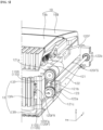
- a display device may be mounted in a cabin 1 of a vehicle.
- the display device may be referred to as a vehicular digital cockpit.
- a plurality of display devices may be mounted in the cabin 1 of the vehicle.
- a main display device 3 may be mounted on a dashboard 2 of the vehicle.
- the main display device 3 may include a cluster 3a, a center information display (CID) 3b, and a co-driver display (CDD) 3c.
- the cluster 3a may provide information to a driver
- the co-driver display 3c may provide information to a passenger on a front passenger seat
- the center information display 3b may provide information to occupants.
- a head-up display (HUD) 4 may be mounted on the dashboard 2, and may display information on a front windshield of the vehicle.
- the head-up display 4 may provide information to the driver while the driver is looking ahead of the vehicle.
- a rear seat entertainment (RSE) 5 may be mounted on a rear surface of the head rest of the driver seat and/or a rear surface of the head rest of the front passenger seat.
- the rear seat entertainment 5 may provide information to a passenger sitting on the rear seat.
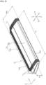
- a display device 10 as the main display device 3 described above with reference to FIG. 1 , may be mounted on the dashboard of the vehicle.
- the display device 10 may be referred to as a vehicular display device 10.
- the display device 10 may extend long in a leftward-rightward direction.
- the height Ha of the display device 10 may be defined in an upward-downward direction, and may be less than the length La of the display device 10.
- the width Wa of the display device 10 may be defined in a forward-backward direction, and may be greater than the height Ha of the display device 10 but less than the length La of the display device 10.
- a side cover 11 may extend along the periphery of the display device 10, and may cover the lateral side of the display device 10.
- a top cover 19 may cover the upper surface of the display device 10.
- a front cover 163 may cover the front surface of the display device 10. The front cover 163 may be referred to as a flap 163.
- Heat dissipation holes 10a may be located between the side cover 11 and the top cover 19, and may be formed along the periphery of the display device 10.
- a first side wall 12R and a second side wall 12L may be located inside the side cover 11.
- the first side wall 12R may be located on the right side of the top cover 19 and the front cover 163
- the second side wall 12L may be located on the left side of the top cover 19 and the front cover 163.
- first side wall 12R and the second side wall 12L may be fixed in position.
- first side wall 12R and the second side wall 12L may be bilaterally symmetrical to each other.
- the first side wall 12R may be open in a direction toward the second side wall 12L, i.e., to the left.
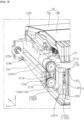
- a first sliding assembly 120a may be mounted in an inner space in the first side wall 12R.
- the first sliding assembly 120a may include a motor 121, a power transmission member 121a, 121b, and 121c, a lead screw 122, a slider 123, and holders 122a and 122b.
- the motor 121 may provide rotational force.
- the motor 121 may be an electric motor configured to be adjustable in rotational direction, rotational angle, and rotational speed, and may include a rotation shaft parallel to the leftward-rightward direction.
- the motor 121 may be adjacent to the rear end of the first side wall 12R, and may be fixed to an inner side of the first side wall 12R.
- the power transmission member 121a, 121b, and 121c may transmit power from the motor 121 to the lead screw 122.
- the power transmission member 121a, 121b, and 121c may include a drive pulley 121a, a driven pulley 121c, and a belt 121b.
- the drive pulley 121a may be orthogonal to the rotation shaft of the motor 121, may be fixed to the rotation shaft, and may be spaced apart from the driven pulley 121c.
- the belt 121b may be engaged with the drive pulley 121a and the driven pulley 121c, and may be referred to as a timing belt. Accordingly, the belt 121b may transmit rotation of the drive pulley 121a to the driven pulley 121c.
- the lead screw 122 may extend in the forward-backward direction.
- the rear end of the lead screw 122 may be adjacent to the rear end of the first side wall 12R, and may be fixed to the driven pulley 121c.
- the front end of the lead screw 122 may be adjacent to the front end of the first side wall 12R.
- the lead screw 122 may include male threads formed on the outer peripheral surface thereof.
- the slider 123 may have a block shape on the whole.
- the lead screw 122 may penetrate the slider 123.
- the slider 123 may include female threads formed on an inner side thereof, and the female threads may be engaged with the male threads of the lead screw 122.
- the slider 123 may be referred to as a lead nut.
- a protruding portion 123a may protrude from a lateral side of the slider 123, and may be fixed to a body 110 to be described later.
- the rear holder 122a may be located between the driven pulley 121c and the slider 123, and may be adjacent to the driven pulley 121c.
- the rear holder 122a may be fixed to an inner side of the first side wall 12R, and the lead screw 122 may be rotatably coupled to the rear holder 122a.
- the front holder 122b may be located opposite the rear holder 122a with respect to the slider 123, and may be adjacent to the front end of the lead screw 122.
- the front holder 122b may be fixed to an inner side of the first side wall 12R, and the lead screw 122 may be rotatably coupled to the front holder 122b.
- the slider 123 may perform linear reciprocating motion along the lead screw 122.
- the slider 123 may move forwardly along the lead screw 122.
- the rotation shaft of the motor 121 rotates in a second rotational direction opposite the first rotational direction, the slider 123 may move backwardly along the lead screw 122.
- the above-described rear holder 122a may restrict the backward movement of the slider 123
- the above-described front holder 122b may restrict the forward movement of the slider 123.
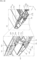
- a first frame 120Fa may be located on the left side of the lead screw 122, and may extend along the lead screw 122.
- the first frame 120Fa may form the right side of the housing 13.
- the housing 13 may include a top part 13T, a rear part 13R, and a bottom part 13B, and the first frame 120Fa may be referred to as a right part 120Fa of the housing 13.
- the first frame 120Fa may be located between the top part 13T and the rear part 13R, and may be coupled to the top part 13T and the rear part 13R.
- This housing 13 may include an open front side.
- a slot 120FS may be formed so as to penetrate the first frame 120Fa in the leftward-rightward direction, and may be formed to be elongated in the forward-backward direction.
- the protruding portion 123a of the slider 123 may pass through the slot 120FS, and may be fixed to a right side 110R of the body 110 located in the housing 13.
- the slot 120FS may restrict rotation of the protruding portion 123a of the lead screw 122.
- a rail 120FR may be coupled to a left side of the first frame 120Fa, and may extend long in the forward-backward direction.
- the rail 120FR may be spaced upward or downward from the slot 120FS.
- Carriages 110S1 and 110S2 may be fixed to the right side 110R of the body 110, and may be coupled to the rail 120FR so as to be movable in the forward-backward direction.
- the carriages 110S1 and 110S2 may include a first carriage 110S1 and a second carriage 110S2, which are located opposite each other with respect to the protruding portion 123a of the slider 123.
- the body 110 fixed to the slider 123 may perform linear reciprocating motion along the rail 120FR.
- the body 110 may move forwardly and backwardly in the housing 13.
- a pin indicator 123b may be formed on the lower surface of the slider 123.
- a rear sensor 124a may be adjacent to the rear holder 122a, and a front sensor 124b may be adjacent to the front holder 122b.
- the sensors 124a and 124b may be photosensors. That is, the sensors 124a and 124b may detect approach of the pin indicator 123b.
- a controller of the display device may determine whether the body 110 has moved backwardly or forwardly to the maximum extent with respect to the housing 13 based on information obtained from the rear sensor 124a or the front sensor 124b.
- the second side wall 12L may be open in a direction toward the first side wall 12R, i.e., to the right.
- the second sliding assembly 120b may be mounted in an inner space in the second side wall 12L.
- the second sliding assembly 120b may be symmetrical to the first sliding assembly 120a described above with reference to FIGs. 4 to 6 .
- the above description of the first sliding assembly 120a may be identically applied to the second sliding assembly 120b.
- a second frame 120Fb may be located on the left side of the lead screw 122, and may extend along the lead screw 122.
- the second frame 120Fb may form the left side of the housing 13.
- the housing 13 may include a top part 13T, a rear part 13R, and a bottom part 13B, and the second frame 120Fb may be referred to as a left part 120Fb of the housing 13.
- the second frame 120Fb may be located between the top part 13T and the rear part 13R, and may be coupled to the top part 13T and the rear part 13R.
- This housing 13 may include an open front side.
- first sliding assembly 120a may be located opposite the right side 110R of the body 110 with respect to the first frame 120Fa, and may be coupled to the right side 110R.
- the second sliding assembly 120b may be located opposite the left side 110L of the body 110 with respect to the second frame 120Fb, and may be coupled to the left side 110L.
- the body 110 may perform linear reciprocating motion due to power transmitted to the left and right sides of the body 110.
- the body 110 may extend long in the leftward-rightward direction.
- the body 110 may have a substantially flat box shape.
- a plurality of displays 130, 140, and 150 may be located in front of the body 110, and may be coupled to the body 110.
- a first display 130 may be disposed at the center of the body 110.
- a second display 140 may be disposed on the left side of the first display 130.
- a third display 150 may be disposed on the right side of the first display 130.
- a portion of the body 110 to which the first display 130 is coupled may be referred to as a first part 113.
- a portion of the body 110 to which the second display 140 is coupled may be referred to as a second part 114.
- a portion of the body 110 to which the third display 150 is coupled may be referred to as a third part 115.
- the first display 130 may be a CID
- the second display 140 may be a CDD
- the third display 150 may be a cluster.
- the shapes, positions, or angles of these plurality of displays 130, 140, and 150 may be varied depending on the forward/backward movement of the body 110. That is, when the body 110 moves backwardly, the screens of the plurality of displays 130, 140, and 150 may be folded or hidden, and when the body 110 moves forwardly, the screens of the plurality of displays 130, 140, and 150 may be unfolded or deployed.
- the first display 130 may be located in front of the first part 113, and may be coupled to a front end 113a of the first part 113.
- the first display 130 may include a folding module and a first display panel 136.
- the folding module may include a first bracket 131, 132, and 133, an upper drive unit 132a, 132b, and 132c, a lower drive unit 133a, 133b, and 133c, an upper plate 134, and a lower plate 135.
- the first display 130 may be a foldable display.
- the first bracket 131, 132, and 133 may have a substantially square bracket shape.
- the first bracket 131, 132, and 133 may include a vertical portion 131, a first horizontal portion 132, and a second horizontal portion 133.
- the vertical portion 131 may extend in the longitudinal direction of the first part 113, the thickness of the vertical portion 131 may be defined in the forward-backward direction, and the width of the vertical portion 131 may be defined in the upward-downward direction.
- the first horizontal portion 132 may be bent and extend forwardly from the upper end of the vertical portion 131, and the thickness of the first horizontal portion 132 may be defined in the upward-downward direction.
- the second horizontal portion 133 may be bent and extend forwardly from the lower end of the vertical portion 131, and the thickness of the second horizontal portion 133 may be defined in the upward-downward direction.
- a first coupling portion 131a may protrude from the rear surface of the vertical portion 131 to the front end 113a of the first part 113, and may be rotatably coupled to the front end 113a.
- the rotation axis of the first coupling portion 131a may be parallel to the leftward-rightward direction.
- the upper drive unit 132a, 132b, and 132c may include an upper motor (not numbered), an upper drive pulley 132a, an upper driven pulley 132c, and an upper belt 132b.
- the upper motor may be mounted inside the first horizontal portion 132, and may provide rotational force.
- the upper motor may be an electric motor configured to be adjustable in rotational direction, rotational angle, and rotational speed, and may include a rotation shaft parallel to the leftward-rightward direction.
- the upper drive pulley 132a may be orthogonal to the rotation shaft of the upper motor, may be fixed to the rotation shaft, and may be spaced apart from the upper driven pulley 132c.
- the upper belt 132b may be engaged with the upper drive pulley 132a and the upper driven pulley 132c, and may be referred to as a timing belt. Accordingly, the upper belt 132b may transmit rotation of the upper drive pulley 132a to the upper driven pulley 132c.
- the lower drive unit 133a, 133b, and 133c may include a lower motor (not numbered), a lower drive pulley 133a, a lower driven pulley 133c, and a lower belt 133b.
- the lower motor may be mounted inside the second horizontal portion 133, and may provide rotational force.
- the lower motor may be an electric motor configured to be adjustable in rotational direction, rotational angle, and rotational speed, and may include a rotation shaft parallel to the leftward-rightward direction.
- the lower drive pulley 133a may be orthogonal to the rotation shaft of the lower motor, may be fixed to the rotation shaft, and may be spaced apart from the lower driven pulley 133c.
- the lower belt 133b may be engaged with the lower drive pulley 133a and the lower driven pulley 133c, and may be referred to as a timing belt. Accordingly, the lower belt 133b may transmit rotation of the lower drive pulley 133a to the lower driven pulley 133c.
- the upper plate 134 may be located in front of the first horizontal portion 132.
- An upper knuckle 134n may be formed on one side of the upper plate 134 that is adjacent to the first horizontal portion 132.
- An upper pin (not shown) may extend in the rotation-axis direction of the upper driven pulley 132c, may penetrate the upper knuckle 134n, and may be fixed to the upper knuckle 134n.
- one end of the upper pin may be fixed to the upper driven pulley 132c, and the other end of the upper pin may be rotatably coupled to an upper holder (not shown) fixed to an inner side of the first horizontal portion 132.
- the upper plate 134 may be hinged to the first horizontal portion 132, and may perform hinge motion in response to operation of the upper motor.
- the hinge axis of the upper plate 134 may be parallel to the leftward-rightward direction.
- an angle between the upper plate 134 and the first horizontal portion 132 may be 180 degrees.
- the upper plate 134 may rotate from the first horizontal portion 132 in the clockwise direction, and an angle between the upper plate 134 and the first horizontal portion 132 may be 90 degrees.
- the lower plate 135 may be located in front of the second horizontal portion 133.
- a lower knuckle 135n may be formed on one side of the lower plate 135 that is adjacent to the second horizontal portion 133.
- a lower pin (not shown) may extend in the rotation-axis direction of the lower driven pulley 133c, may penetrate the lower knuckle 135n, and may be fixed to the lower knuckle 135n.
- one end of the lower pin may be fixed to the lower driven pulley 133c, and the other end of the lower pin may be rotatably coupled to a lower holder 133d fixed to an inner side of the second horizontal portion 133.
- the lower plate 135 may be hinged to the second horizontal portion 133, and may perform hinge motion in response to operation of the lower motor.
- the hinge axis of the lower plate 135 may be parallel to the leftward-rightward direction.
- an angle between the lower plate 135 and the second horizontal portion 133 may be 180 degrees.
- the lower plate 135 may rotate from the second horizontal portion 133 in the counterclockwise direction, and an angle between the lower plate 135 and the second horizontal portion 133 may be 90 degrees.
- the first display panel 136 may be located opposite the first bracket 131, 132, and 133 with respect to the upper plate 134 and the lower plate 135.
- the first display panel 136 may be coupled to the upper plate 134 and the lower plate 135.
- One end of the first display panel 136 may be coupled to an inner side of the upper plate 134, and the other end of the first display panel 136 may be coupled to an inner side of the lower plate 135.
- the first display panel 136 may be a flexible display panel.
- the first display panel 136 may be an organic light-emitting diode (OLED) panel or plastic OLED (POLED) panel. Accordingly, the first display panel 136 may be bent.
- OLED organic light-emitting diode
- POLED plastic OLED
- the first part 113 of the body 110 may be adjacent to the rear end of the housing 13 in the housing 13.
- the upper plate 134 and the lower plate 135 may oppose each other in the upward-downward direction, and the first display panel 136 may be bent so as to be convex backward.
- the first part 113 of the body 110 may be adjacent to the front end of the housing 13 in the housing 13.
- a direction perpendicular to the upper plate 134 and a direction perpendicular to the lower plate 135 may be oriented forward, and the first display panel 136 may be unfolded to be flat.
- the door 162 may form the lower surface of the display device, and may be shifted up and down with respect to the housing 13 (refer to "SH" in FIG. 11 ). That is, in response to forward movement of the body 110 and the first display 130, the door 162 may be shifted down with respect to the housing 13, thereby increasing the inner space in the display device. Alternatively, in response to backward movement of the body 110 and the first display 130, the door 162 may be shifted up with respect to the housing 13, thereby reducing the inner space in the display device.
- supporters 137 and 138 may be spaced leftward and/or rightward from the drive units 132a, 132b, 132c, 133a, 133b, and 133c described above with reference to FIGs. 10 and 11 .
- An upper supporter 137 may be provided on one side of the upper plate 134 that is adjacent to the first horizontal portion 132, and may be rotatably coupled to the upper holder (not shown) fixed to an inner side of the first horizontal portion 132.
- the rotation axis of the upper supporter 137 may be parallel to the rotation axis of the upper driven pulley 132c (refer to FIGs. 10 and 11 ).
- An upper arm 137a which is a part of the upper supporter 137, may extend in the radial direction of the upper supporter 137.
- This upper arm 137a may overlap the inner side of the first horizontal portion 132 in the rotational direction of the upper supporter 137. In other words, when the upper arm 137a comes into contact with the inner side of the first horizontal portion 132, rotation of the upper plate 134 in the counterclockwise direction may be restricted.
- a lower supporter 138 may be provided on one side of the lower plate 135 that is adjacent to the second horizontal portion 133, and may be rotatably coupled to a lower holder 133e fixed to an inner side of the second horizontal portion 133.
- the rotation axis of the lower supporter 138 may be parallel to the rotation axis of the lower driven pulley 133c (refer to FIGs. 10 and 11 ).
- a lower arm 138a, which is a part of the lower supporter 138, may extend in the radial direction of the lower supporter 138.
- This lower arm 138a may overlap the inner side of the second horizontal portion 133 in the rotational direction of the lower supporter 138. In other words, when the lower arm 138a comes into contact with the inner side of the second horizontal portion 133, rotation of the lower plate 135 in the clockwise direction may be restricted.
- the upper arm 137a and the lower arm 138a may come into contact with or become adjacent to each other in response to hinge motion of the upper plate 134 and the lower plate 135 (refer to dotted lines and solid-line arrows in FIG. 12 ).
- the upper arm 137a and the lower arm 138a may support the rear surface of the first display panel 136.
- a portion 134a of the upper plate 134 may cover an upper side of the first display panel 136, and a portion 135a of the lower plate 135 may cover a lower side of the first display panel 136. Further, left and right sides of the first display panel 136 may also be covered by the upper plate 134 and the lower plate 135.
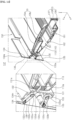
- a tilting module 139a, 139b, and 139c may be mounted inside the second part 114 of the body 110.
- the tilting module 139a, 139b, and 139c may include a tilting motor (not numbered), a drive pulley 139a, a driven pulley 139c, and a belt 139b.
- the tilting motor may be mounted inside the second part 114, and may provide rotational force.
- the tilting motor may be an electric motor configured to be adjustable in rotational direction, rotational angle, and rotational speed, and may include a rotation shaft parallel to the leftward-rightward direction.
- the drive pulley 139a may be orthogonal to the rotation shaft of the tilting motor, may be fixed to the rotation shaft, and may be spaced apart from the driven pulley 139c.
- the belt 139b may be engaged with the drive pulley 139a and the driven pulley 139c, and may be referred to as a timing belt. Accordingly, the belt 139b may transmit rotation of the drive pulley 139a to the driven pulley 193c.
- This driven pulley 139c may be axially coupled to the first coupling portion 131a (refer to FIG. 11 ). That is, the rotation shaft of the first coupling portion 131a may be coaxial with the rotation axis of the driven pulley 139c.
- the first display 130 may be tilted up and down (refer to "tilt" in FIG. 13 ).
- the first display 130 may be tilted up and down in the range of about 10 degrees.
- the tilting module 139a, 139b, and 139c may be mounted inside the first part 113 or the third part 115.
- the second display 140 may be coupled to a front end of the second part 114.
- the second display 140 may include a swing module and a second display panel 146.
- the swing module may include a second bracket 141, a drive unit 142a, 142b, and 142c, a holder 143, and a plate 145.
- the second display 140 may be referred to as a swing display or a rotatable display.
- the second bracket 141 may extend in the leftward-rightward direction.
- the second bracket 141 may be located in a groove 114g in the second part 114, and may be rotatably coupled to the second part 114.
- the groove 114g may be formed in the front end of the second part 114 so as to be depressed backward, and may be open downward.
- a first surface 114g1 may define the rear boundary of the groove 114g, and a second surface 114g2 may define the upper boundary of the groove 114g.
- the first surface 114g1 and the second surface 114g2 may intersect each other. For example, an angle between the first surface 114g1 and the second surface 114g2 may be 90 degrees or an obtuse angle.
- the drive unit 142a, 142b, and 142c may be located on the left side of the second bracket 141.
- the drive unit 142a, 142b, and 142c may be located in a portion of the second part 114 that is located on the left side of the groove 114g.
- the drive unit 142a, 142b, and 142c may include a swing motor (not numbered), a drive pulley 142a, a driven pulley 142c, and a belt 142b.
- the swing motor may be mounted inside the second part 114, and may provide rotational force.
- the swing motor may be an electric motor configured to be adjustable in rotational direction, rotational angle, and rotational speed, and may include a rotation shaft parallel to the leftward-rightward direction.
- the drive pulley 142a may be orthogonal to the rotation shaft of the swing motor, may be fixed to the rotation shaft, and may be spaced apart from the driven pulley 142c.
- the belt 142b may be engaged with the drive pulley 142a and the driven pulley 142c, and may be referred to as a timing belt. Accordingly, the belt 142b may transmit rotation of the drive pulley 142a to the driven pulley 142c.
- the holder 143 may be located on the right side of the second bracket 141.
- the holder 143 may be a portion of the second part 114 that is located on the right side of the groove 114g.
- the holder 143 may be located opposite the drive unit 142a, 142b, and 142c with respect to the second bracket 141.
- the above-described second bracket 141 may be located between the driven pulley 142c and the holder 143, and may be axially coupled to the driven pulley 142c and the holder 143. That is, a shaft 141a of the second bracket 141 may extend long in the leftward-rightward direction. One end of the shaft 141a may be fixed to the driven pulley 142c, and the other end of the shaft 141a may be rotatably coupled to the holder 143.
- the second bracket 141 may be rotatably coupled to the second part 114 of the body 110, and may perform swing motion in response to operation of the swing motor.
- the shaft 141a may provide a swing axis of the second bracket 141 parallel to the leftward-rightward direction.
- the second bracket 141 may rotate between the first surface 114g1 and the second surface 114g2. In other words, when the second bracket 141 comes into contact with the first surface 114g1, rotation of the second bracket 141 in the counterclockwise direction may be restricted, and when the second bracket 141 comes into contact with the second surface 114g2, rotation of the second bracket 141 in the clockwise direction may be restricted.
- the plate 145 may be located opposite the second part 114 with respect to the second bracket 141.
- the second bracket 141 may protrude from the plate 145 in a direction intersecting the plate 145.
- the second bracket 141 may connect the plate 145 to the second part 114.
- the second display panel 146 may be located opposite the second bracket 141 with respect to the plate 145.
- the second display panel 146 may be coupled to the plate 145. Portions 145a and 145b of the plate 145 may cover the lateral side of the second display panel 146.
- the second display panel 146 may be an organic light-emitting diode (OLED) panel or plastic OLED (POLED) panel.
- the second display panel 146 may be a liquid crystal display (LCD) panel.
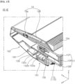
- the second part 114 of the body 110 may be adjacent to the rear end of the housing 13 in the housing 13.
- the second bracket 141 may protrude downward beyond the second part 114, and may be in contact with the first surface 114g1.
- the second display panel 146 may be located below the second part 114, and may be parallel to the second part 114.
- the second part 114 of the body 110 may be adjacent to the front end of the housing 13 in the housing 13.
- the second bracket 141 may protrude forward beyond the second part 114, and may be in contact with the second surface 114g2.
- the second display panel 146 may be located in front of the second part 114, and may be orthogonal to the second part 114.
- the door 162 may form the lower surface of the display device, and may be shifted up and down with respect to the housing 13 (refer to "SH" in FIG. 15 ). That is, in response to forward movement of the body 110 and the second display 140, the door 162 may be shifted down with respect to the housing 13, thereby increasing the inner space in the display device. Alternatively, in response to backward movement of the body 110 and the second display 140, the door 162 may be shifted up with respect to the housing 13, thereby reducing the inner space in the display device.
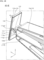
- the second display 140 may be located in front of the second part 114 of the body 110, and may be tilted up and down in response to operation of the swing motor (refer to "tilt" in FIG. 16 ).
- the second display 140 may be tilted up and down in the range of about 10 degrees.
- the swing motor may be referred to as a tilting motor.
- the third display 150 may be coupled to a front end of the third part 115.
- the third display 150 may include a swing module and a third display panel 156.
- the swing module may include a third bracket 151, a drive unit 152a, 152b, and 152c, a holder 153, and a plate 155.
- the third display 140 may be referred to as a swing display or a rotatable display.
- the third bracket 151 may extend in the leftward-rightward direction.
- the third bracket 151 may be located in a groove 115g in the third part 115, and may be rotatably coupled to the third part 115.
- the groove 115g may be formed in the front end of the third part 115 so as to be depressed backward, and may be open downward.
- a first surface 115g1 may define the rear boundary of the groove 115g, and a second surface 115g2 may define the upper boundary of the groove 115g.
- the first surface 115g1 and the second surface 115g2 may intersect each other. For example, an angle between the first surface 115g1 and the second surface 115g2 may be 90 degrees or an obtuse angle.
- the drive unit 152a, 152b, and 152c may be located on the left side of the third bracket 151.
- the drive unit 152a, 152b, and 152c may be located in a portion of the third part 115 that is located on the left side of the groove 115g.
- the drive unit 152a, 152b, and 152c may include a swing motor (not numbered), a drive pulley 152a, a driven pulley 152c, and a belt 152b.
- the swing motor may be mounted inside the fifth part 115, and may provide rotational force.
- the swing motor may be an electric motor configured to be adjustable in rotational direction, rotational angle, and rotational speed, and may include a rotation shaft parallel to the leftward-rightward direction.
- the drive pulley 152a may be orthogonal to the rotation shaft of the swing motor, may be fixed to the rotation shaft, and may be spaced apart from the driven pulley 152c.
- the belt 152b may be engaged with the drive pulley 152a and the driven pulley 152c, and may be referred to as a timing belt. Accordingly, the belt 152b may transmit rotation of the drive pulley 152a to the driven pulley 152c.
- the holder 153 may be located on the right side of the third bracket 151.
- the holder 153 may be a portion of the third part 115 that is located on the right side of the groove 115g.
- the holder 153 may be located opposite the drive unit 152a, 152b, and 152c with respect to the third bracket 151.
- the above-described third bracket 151 may be located between the driven pulley 152c and the holder 153, and may be axially coupled to the driven pulley 152c and the holder 153. That is, a shaft 151a of the third bracket 151 may extend long in the leftward-rightward direction. One end of the shaft 151a may be fixed to the driven pulley 152c, and the other end of the shaft 151a may be rotatably coupled to the holder 153.
- the third bracket 151 may be rotatably coupled to the third part 115 of the body 110, and may perform swing motion in response to operation of the swing motor.
- the shaft 151a may provide a swing axis of the third bracket 151 parallel to the leftward-rightward direction.
- the third bracket 151 may rotate between the first surface 115g1 and the second surface 115g2. In other words, when the third bracket 151 comes into contact with the first surface 115g1, rotation of the third bracket 151 in the counterclockwise direction may be restricted, and when the third bracket 151 comes into contact with the second surface 115g2, rotation of the third bracket 151 in the clockwise direction may be restricted.
- the plate 155 may be located opposite the third part 115 with respect to the third bracket 151.
- the third bracket 151 may protrude from the plate 155 in a direction intersecting the plate 155.
- the third bracket 151 may connect the plate 155 to the third part 115.
- the third display panel 156 may be located opposite the third bracket 151 with respect to the plate 155.
- the third display panel 156 may be coupled to the plate 155. Portions 155a and 155b of the plate 155 may cover the lateral side of the third display panel 156.
- the third display panel 156 may be an organic light-emitting diode (OLED) panel or plastic OLED (POLED) panel.
- the third display panel 156 may be a liquid crystal display (LCD) panel.
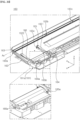
- the third part 115 of the body 110 may be adjacent to the rear end of the housing 13 in the housing 13.
- the third bracket 151 may protrude downward beyond the third part 115, and may be in contact with the first surface 115g1.
- the third display panel 156 may be located below the third part 115, and may be parallel to the third part 115.
- the third part 115 of the body 110 may be adjacent to the front end of the housing 13 in the housing 13.
- the third bracket 151 may protrude forward beyond the third part 115, and may be in contact with the second surface 115g2.
- the third display panel 156 may be located in front of the third part 115, and may be orthogonal to the third part 115.
- the door 162 may form the lower surface of the display device, and may be shifted up and down with respect to the housing 13 (refer to "SH" in FIG. 18 ). That is, in response to forward movement of the body 110 and the third display 150, the door 162 may be shifted down with respect to the housing 13, thereby increasing the inner space in the display device. Alternatively, in response to backward movement of the body 110 and the third display 150, the door 162 may be shifted up with respect to the housing 13, thereby reducing the inner space in the display device.
- the third display 150 may be located in front of the third part 115 of the body 110, and may be tilted up and down in response to operation of the swing motor (refer to "tilt" in FIG. 19 ).
- the third display 150 may be tilted up and down in the range of about 10 degrees.
- the swing motor may be referred to as a tilting motor.
- the door assembly 160 may include a base 161, a door 162, and a flap 163.
- the base 161 may form a portion of the lower surface of the display device.
- the base 161 may be coupled to a lower side of the bottom part 13B of the housing 13 (refer to FIGs. 11 , 15 , and 18 ).
- the base 161 may extend long in the leftward-rightward direction.
- the door 162 may form a portion of the lower surface of the display device.
- the door 162 may extend in the longitudinal direction of the base 161.
- the door 162 may be located in front of the base 161, and may be rotatably or pivotably coupled to the base 161.
- the door 162 may be inclined upward with respect to the base 161. For example, an angle ⁇ a between the door 162 and the base 161 may be an acute angle.
- the flap 163 may form a portion of the front surface of the display device.
- the flap 163 may extend in the longitudinal direction of the door 162.
- the flap 163 may intersect the door 162, and may be rotatably coupled to the front end of the door 162.
- a pivot assembly 164, 164a, 165, 166, 167, 167a, 168, and 169 may include pivot motors 164, 164a, 167, and 167a and pivot arms 165, 166, 168, and 169.
- the pivot motors 164, 164a, 167, and 167a may be mounted on the base 161, and may provide rotational force.
- the pivot motors 164, 164a, 167, and 167a may be electric motors configured to be adjustable in rotational direction, rotational angle, and rotational speed, and may include a rotation shaft parallel to the leftward-rightward direction.
- a first pivot arm 165 and a second pivot arm 166 may be located on the door 162, and may be adjacent to the left side of the door 162.
- a third pivot arm 168 and a fourth pivot arm 169 may be located on the door 162, and may be adjacent to the right side of the door 162.
- the pivot arms 165, 166, 168, and 169 may have the same shape.
- each of the pivot arms 165, 166, 168, and 169 may have a rifle shape on the whole.
- the first pivot arm 165 may include a first pivot point 165a, a first middle point 165b, and a first top point 165c, which are spaced apart from one another.
- the first pivot point 165a may be adjacent to the rear end of the first pivot arm 165, and may be located on the base 161.
- the first middle point 165b may be adjacent to the center portion of the first pivot arm 165, may be located on the door 162, and may be adjacent to the boundary between the door 162 and the base 161.
- the first top point 165c may be adjacent to the front end of the first pivot arm 165, may be located on the door 162, and may be spaced apart from the first middle point 165b in the width direction of the door 162.
- a first pivot motor 164 may be mounted on the base 161, and may be adjacent to the first pivot arm 165.
- the rotation shaft of the first pivot motor 164 may be fixed to the first pivot point 165a. That is, the pivot axis of the first pivot arm 165 may be coaxial with the rotation shaft of the first pivot motor 164, and may be parallel to the leftward-rightward direction.
- a first coupling portion 1621 may protrude upward from the upper surface of the door 162, and the first middle point 165b and the first top point 165c of the first pivot arm 165 may be coupled or fixed to the first coupling portion 1621.
- the second pivot arm 166 may be located closer to the left side of the door 162 than the first pivot arm 165.
- the second pivot arm 166 may have the same shape as the first pivot arm 165.
- a second pivot point 166a of the second pivot arm 166 may be aligned with the first pivot point 165a of the first pivot arm 165 in the leftward-rightward direction.
- a second pivot motor 164a may be mounted on the base 161, and may be adjacent to the second pivot arm 166.
- the rotation shaft of the second pivot motor 164a may be fixed to the second pivot point 166a. That is, the pivot axis of the second pivot arm 166 may be coaxial with the rotation shaft of the second pivot motor 164a, and may be parallel to the leftward-rightward direction.
- a second coupling portion 1622 may protrude upward from the upper surface of the door 162, and a second middle point (not shown) and a second top point (not shown) of the second pivot arm 166 may be coupled or fixed to the second coupling portion 1622.
- the third pivot arm 168 may include a third pivot point 168a, a third middle point 168b, and a third top point 168c, which are spaced apart from one another.
- the third pivot point 168a may be adjacent to the rear end of the third pivot arm 168, and may be located on the base 161.
- the third middle point 168b may be adjacent to the center portion of the third pivot arm 168, may be located on the door 162, and may be adjacent to the boundary between the door 162 and the base 161.
- the third top point 168c may be adjacent to the front end of the third pivot arm 168, may be located on the door 162, and may be spaced apart from the third middle point 168b in the width direction of the door 162.
- a third pivot motor 167 may be mounted on the base 161, and may be adjacent to the third pivot arm 168.
- the rotation shaft of the third pivot motor 167 may be fixed to the third pivot point 168a. That is, the pivot axis of the third pivot arm 168 may be coaxial with the rotation shaft of the third pivot motor 167, and may be parallel to the leftward-rightward direction.
- a third coupling portion 1623 may protrude upward from the upper surface of the door 162, and the third middle point 168b and the third top point 168c of the third pivot arm 168 may be coupled or fixed to the third coupling portion 1623.
- the fourth pivot arm 169 may be located closer to the right side of the door 162 than the third pivot arm 168.
- the fourth pivot arm 169 may have the same shape as the third pivot arm 168.
- a fourth pivot point 169a of the fourth pivot arm 169 may be aligned with the third pivot point 168a of the third pivot arm 168 in the leftward-rightward direction.
- the first pivot points 165a, 166a, 168a, and 169a may be aligned with each other in the leftward-rightward direction.
- a fourth pivot motor 167a may be mounted on the base 161, and may be adjacent to the fourth pivot arm 169.
- the rotation shaft of the fourth pivot motor 167a may be fixed to the fourth pivot point 169a. That is, the pivot axis of the fourth pivot arm 169 may be coaxial with the rotation shaft of the fourth pivot motor 167a, and may be parallel to the leftward-rightward direction.
- a fourth coupling portion 1624 may protrude upward from the upper surface of the door 162, and a fourth middle point (not shown) and a fourth top point (not shown) of the fourth pivot arm 169 may be coupled or fixed to the fourth coupling portion 1624.
- the door 162 may pivot about the pivot axes of the pivot arms 165, 166, 168, and 169. That is, the door 162 may be shifted up and down with respect to the base 161 (refer to "SH" in FIG. 21 ).
- the above-described flap 163 may be hinged to the front end of the door 162 at a plurality of points 163a, 163b, 163c, and 163d.
- the hinge axis Ax of the flap 163 may be parallel to the leftward-rightward direction.
- a link assembly 170 and 180 may connect the upper side of the door 162 to the inner side of the flap 163.
- the link assembly 170 and 180 may include a first link assembly 170 and a second link assembly 180, which are spaced apart from each other in the leftward-rightward direction.
- the link assembly 170 and 180 may include one or three or more link assemblies.
- the link assembly 170 and 180 includes the first link assembly 170 and the second link assembly 180.
- the first link assembly 170 may include a link motor 171, a first link arm 172, and a second link arm 173.
- the link motor 171 may be mounted on the door 162, and may provide rotational force.
- the link motor 171 may be an electric motor configured to be adjustable in rotational direction, rotational angle, and rotational speed, and may include a rotation shaft parallel to the leftward-rightward direction.
- One end 172a of the first link arm 172 may be fixed to the rotation shaft of the link motor 171.
- One end 173a of the second link arm 173 may be rotatably connected to the other end of the first link arm 172.
- the other end 173b of the second link arm 173 may be rotatably connected to an inner side of the flap 163.
- the second link assembly 180 may include a link motor 181, a first link arm 182, and a second link arm 183.
- the link motor 181 may be mounted on the door 162, and may provide rotational force.
- the link motor 181 may be an electric motor configured to be adjustable in rotational direction, rotational angle, and rotational speed, and may include a rotation shaft parallel to the leftward-rightward direction.
- One end 182a of the first link arm 182 may be fixed to the rotation shaft of the link motor 181.
- One end 183a of the second link arm 183 may be rotatably connected to the other end of the first link arm 182.
- the other end 183b of the second arm 183 may be rotatably connected to an inner side of the flap 163.
- the link arms 172, 173, 182, and 183 may be folded or unfolded.
- the first link arms 172 and 182 may be reclined backward, and the link arms 172, 173, 182, and 183 may be folded.
- the flap 163 may be reclined while performing hinge motion in the counterclockwise direction from the door 162.
- the first link arms 172 and 183 may be erected forward, and the link arms 172, 173, 182, and 183 may be unfolded.
- the flap 163 may be erected while performing hinge motion in the clockwise direction from the door 162.
- each of the pivot arms 165, 166, 168, and 169 may have a knife shape on the whole.
- Each of the pivot arms 165, 166, 168, and 169 having such a shape may include points such as the third pivot point 168a and the third middle points 168b and 168c described above.
- the door assembly may include one link assembly 170. That is, the flap 163 may be reclined backward (refer to FIG. 24 ) or erected forward in response to the folding motion of the link assembly 170.
- the door 162 in response to forward movement of the body 110 and the displays 130, 140, and 150, the door 162 may be shifted down with respect to the base 161 (refer to "SH"), and may deviate from the movement paths of the body 110 and the displays 130, 140, and 150.
- the flap 163 in response to forward movement of the body 110 and the displays 130, 140, and 150, the flap 163 may be reclined backward (refer to "RH”), and may expose the front sides of the body 110 and the displays 130, 140, and 150.
- the door 162 may be shifted down.
- the flap 163 may be reclined to the inside of the display device.
- the door 162 may be shifted up.
- the flap 163 may be erected to cover the inside of the display device.
- the first display 130, the second display 140, and the third display 150 may move forward from the inside of the display device.
- the first display panel 136 of the first display 130 may be made flat from a state of being convex backward, and the second display panel 146 of the second display 140 and the third display panel 156 of the third display 150 may swing so as to face forward from a state of facing downward.
- each of the first display 130, the second display 140, and the third display 150 may be tilted up and down (refer to "T1", "T2", and "T3").
- the first display 130, the second display 140, and the third display 150 may move backward to the inside of the display device.
- the first display panel 136 of the first display 130 may be bent so as to be convex backward from the flat state, and the second display panel 146 of the second display 140 and the third display panel 156 of the third display 150 may swing so as to face downward from the state of facing forward.
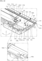
- a folding assembly 190 may connect the top part 13T of the housing 13 to the inner side of the top cover 19.
- the folding assembly 190 may include a first folding assembly (not shown) located on the right side of the top cover 19 and a second folding assembly 190b located on the left side of the top cover 19.
- the folding assembly 190 may include one or three or more folding assemblies.
- the present disclosure will be described based on a case in which the folding assembly 190 includes the first folding assembly and the second folding assembly 190b.
- the first folding assembly and the second folding assembly 190b may be bilaterally symmetrical to each other, and the description of the second folding assembly 190b may be equally applied to the first folding assembly.
- the second folding assembly 190b may include a folding motor (not shown), a drive pulley 191a, a driven pulley 191c, a belt 191b, a folding arm 192, and a connecting member 193.
- the folding motor may be mounted on the top part 13T, and may provide rotational force.
- the folding motor may be an electric motor configured to be adjustable in rotational direction, rotational angle, and rotational speed, and may include a rotation shaft parallel to the leftward-rightward direction.
- the drive pulley 191a may be orthogonal to the rotation shaft of the folding motor, may be fixed to the rotation shaft, and may be spaced apart from the driven pulley 191c.
- the belt 191b may be engaged with the drive pulley 191a and the driven pulley 191c, and may be referred to as a timing belt. Accordingly, the belt 191b may transmit rotation of the drive pulley 191a to the driven pulley 191c.
- the folding arm 192 may extend long. One end 192a of the folding arm 192 may be fixed to the driven pulley 191c. The other end 192b of the folding arm 192 may be rotatably coupled to a portion of the top cover 19 that is adjacent to the rear end of a first cover 19a. The rotation axis Axa of the first cover 19a may be parallel to the leftward-rightward direction.
- the connecting member 193 may be coupled to an inner side of a second cover 19b of the top cover 19.
- the second cover 19b may be located behind the first cover 19a.
- One end 193a of the connecting member 193 may be hinged to a portion of the first cover 19a between the other end 192b of the folding arm 192 and the rear end of the first cover 19a.
- the hinge axis Axb of one end 193a of the connecting member 193 may be parallel to the leftward-rightward direction.
- the other end 193b of the connecting member 193 may be hinged to a portion of the top part 13T in which the heat dissipation holes 10a are formed.
- the hinge axis Axe of the other end 193b of the connecting member 193 may be parallel to the leftward-rightward direction.
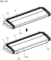
- the folding arm 192 may be reclined or erected, and the top cover 19 may be unfolded or folded.
- the folding arm 192 may be reclined, and the top cover 19 may be unfolded.
- the top cover 19 may cover the upper surface of the top part 13T and a plurality of electronic components B1, B2, B3, and B4 mounted on the upper surface.
- the folding arm 192 may be erected, and the top cover 19 may be folded.
- the first cover 19a may perform hinge motion with the front end thereof moving downward and the rear end thereof moving upward
- the second cover 19b may perform hinge motion with the front end thereof moving upward
- the first cover 19a and the second cover 19b may overlap each other.
- the top cover 19 may expose the upper surface of the top part 13T and the plurality of electronic components B1, B2, B3, and B4 mounted on the upper surface to the outside.
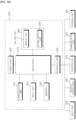
- a display device 200 for a vehicle may include a communication unit 210, an input unit 220, a memory 230, an interface unit 250, an output unit 260, a processor 270, and a power supply 290.
- the display device 200 for vehicles may be the display device 10 for the vehicle.
- the processor 270 may be referred to as a main controller 270 or a first controller 270.
- the communication unit 210 may perform data communication with another device located inside or outside the vehicle.
- the other device may include at least one of a terminal, a mobile terminal, a server, or another vehicle.
- the communication unit 210 may include at least one of a V2X communication module, an optical communication module, a position information module, or a short-range communication module.
- the input unit 220 may receive various inputs for the display device 200 for the vehicle.
- the input unit 220 may receive a user input for the display device 200 for the vehicle.
- the display device 200 for the vehicle may operate.
- the input unit 220 may be electrically connected to the processor 270.
- the input unit 220 may generate a signal corresponding to the received input, and may provide the signal to the processor 270.
- the processor 270 may control the display device 200 for the vehicle in response to the input for the display device 200 for the vehicle received through the input unit 220.
- the input unit 220 may receive an activation input for various functions of the display device 200 for the vehicle.
- the input unit 220 may receive a setting input for an output mode of the output unit 260.
- the input unit 220 may include at least one of a mechanical type input device, a touch type input device, or a wireless input device.
- the mechanical type input device may include a button, a lever, a jog wheel, a switch, and the like.
- the touch type input device may include at least one touch sensor.
- the touch type input device may be implemented as a touchscreen.
- the processor 270 may generate and output a travel route along which the vehicle travels to the specific point corresponding to the received touch input, or may control the vehicle so that the vehicle travels autonomously to the specific point.
- the wireless input device may receive a user input in a wireless manner.
- the memory 230 may store a program for processing or control of the processor 270, various types of data on operation of the display device 200 for the vehicle, and at least one piece of content.
- the memory 230 may be electrically connected to the processor 270.
- the processor 270 may allow various types of data on operation of the display device 200 for the vehicle to be stored in the memory 230.
- the processor 270 may output the content stored in the memory 230 to the output unit 260.
- the interface unit 250 may serve as a channel between the display device 200 for the vehicle and an external device.
- the interface unit 250 may receive various signals or information from the outside, or may transmit signals or information provided by the processor 270 to the outside.
- the interface unit 250 may be connected to the processor 270, an input unit 320, a vehicle driving unit 350, a controller 370, a communication unit 310, and a sensing unit 325 to perform data communication.
- the controller 370 may be referred to as a sub-controller 370 or a second controller 370.
- the interface unit 250 may provide driving information of the vehicle provided from at least one of the input unit 320, the vehicle driving unit 350, the controller 370, the communication unit 310, or the sensing unit 325 to the processor 270.
- the driving information may include information on at least one of a position of the vehicle, a travel route, a speed, an autonomous travel state, a driving mode, a fuel amount, a charging amount, a vehicle type, a state of a driver, or a time.
- the driving mode may include an eco mode for travel based on fuel efficiency, a sport mode for sporty driving, and a normal mode.
- the interface unit 250 may provide a signal provided by the processor 270 to the controller 370 or the vehicle driving unit 350.
- the signal provided to the controller 370 or the vehicle driving unit 350 may be a signal for control of the vehicle.
- the controller 370 may control the vehicle in response to a signal for control of the vehicle.
- the vehicle driving unit 350 may be driven in response to a signal for control of the vehicle.
- the output unit 260 may include display units 130, 140, and 150 configured to output images and a sound output unit 262 configured to output sound.
- the above-described displays 130, 140, and 150 may be referred to as the display units 130, 140, and 150.
- the display units 130, 140, and 150 may display various graphic objects.
- the display units 130, 140, and 150 may include a cluster that allows a driver to check vehicle travel information or vehicle state information.
- the cluster may be located on a dashboard. The driver may check information displayed on the cluster while looking forward.
- the display units 130, 140, and 150 may be implemented as a head-up display (HUD).
- HUD head-up display
- information may be output through a transparent display provided on a windshield.
- the display units 130, 140, and 150 may include a projection module to output information through an image projected on the windshield.
- a transparent display may have certain transparency and may display a certain screen.
- the transparent display may include a transparent organic light-emitting diode (OLED) in order to have transparency.
- OLED transparent organic light-emitting diode
- the transparency of the transparent display may be adjusted.
- a touch input device included in the display units 130, 140, and 150 and the input unit 220 may have a mutual layer structure or may be formed in an integral type to implement a touchscreen.
- the touchscreen may function as the input unit 220 that provides an input interface between the display device 200 for the vehicle and a user, and may also provide an output interface between the display device 200 for the vehicle and the user.
- the display units 130, 140, and 150 may include a touch sensor configured to detect a touch in order to receive a control command input in a touch manner.
- the touch sensor may detect the touch, and the processor 270 may generate a control command corresponding to the touch based thereon.
- the content input in a touch manner may be a character or a number or may be an instruction in various modes or a menu item that can be designated.
- the display units 130, 140, and 150 may be electrically connected to the processor 270 to be controlled by the processor 270.
- the processor 270 may output an image of content or a screen of navigation through the display units 130, 140, and 150.
- the navigation may be an application program for guiding a travel route of the vehicle, and may include a screen showing a travel route or a guidance voice.
- the sound output unit 262 may output a sound corresponding to an electric signal provided by the processor 270.
- the sound output unit 262 may include a speaker or the like.
- the processor 270 may output a sound of content or a guidance voice of navigation through the sound output unit 262.
- the processor 270 may control overall operation of each unit in the display device 200 for the vehicle.
- the processor 270 may be electrically connected to the communication unit 210, the input unit 220, the memory 230, the interface unit 250, the power supply 290, and the output unit 260.
- the processor 270 may be electrically connected to the above-described drive module, and may control operation of the drive module.
- the drive module may include the sliding assembly 120 (refer to FIGs. 4 to 7 ), the folding module of the first display 130 (refer to FIGs. 10 and 11 ), the tilting module 139a, 139b, and 139c of the first display 130 (refer to FIG. 13 ), the swing module of the second display 140 (refer to FIGs. 14 and 15 ), the swing module of the third display 150 (refer to FIGs. 17 and 18 ), the pivot assembly 164, 164a, 165, 166, 167, 167a, 168, and 169 (refer to FIGs. 20 to 24 ), the link assembly 170 and 180 (refer to FIGs. 21 to 24 ), and the folding assembly 190 (refer to FIG. 28 ).
- a display device for the vehicle may include: a housing with an open side; a sliding assembly located in the housing and including a slider which is movable away from or toward the opening; a body located in the housing and fixed to the slider; and a display coupled to the body, and which is movable out of the housing through the opening, the display may include: a display panel; and a swing module which is located between the display panel and the body, to which the display panel is coupled, and which is rotatably coupled to the body, and a rotation axis of the swing module may intersect a movement direction of the body.
- the display panel may be located in the housing or may be located outside the housing through the opening of the housing according to a movement of the body.
- the swing module When the display panel is located in the housing, the swing module may be rotated such that the display panel is parallel to the body, and when the display panel is located outside the housing, the swing module may be rotated such that the display panel intersects the body.
- the swing module may include a plate to which the display panel is coupled, a bracket protruding from the plate toward the body and rotatably coupled to the body, and a drive unit coupled to the bracket and rotating the bracket about the rotation axis.
- the swing module may further include a holder opposite the drive unit with respect to the bracket, and the bracket may further include a shaft extending along the rotation axis, and including one end connected to the drive unit and another end rotatably coupled to the holder.
- the body may extend along the rotation axis, the drive unit may be adjacent to one end of the bracket in the longitudinal direction of the body, and the holder may be a portion of the body adjacent to the other end of the bracket in the longitudinal direction of the body.
- the body may further include a groove depressed from one side of the body facing the bracket, a first surface defining a boundary of one side of the groove in the rotation direction of the bracket, and a second surface defining a boundary of another side of the groove in the rotation direction of the bracket, and the bracket may overlap the first surface and the second surface in the rotation direction of the bracket.
- the drive unit may include a swing motor mounted to the body and providing rotational force, a drive pulley fixed to a rotation shaft of the swing motor, a driven pulley spaced apart from the drive pulley, and a belt engaged with the drive pulley and the driven pulley, wherein the end of the shaft may be fixed to the driven pulley, and a rotation axis of the shaft may be coaxial with the rotation axis of the driven pulley.
- the display may further include a pair of displays adjacent to or spaced apart from each other along the body.
- the display device for the vehicle may further include a foldable display located between the pair of displays and coupled to the body, and the foldable display may include: a flexible display panel; and a folding module located between the flexible display panel and the body, to which the flexible display panel is coupled, and configured to bend or unfold the flexible display panel.
- the sliding assembly may include a lead screw extending in a movement direction of the slider, a motor providing rotational force, and a power transmission member transmitting the rotational force from the motor to the lead screw, wherein the lead screw may penetrate the slider and may be engaged with the slider, and the slider may include a protruding portion protruding from a lateral side of the slider toward the side of the body and fixed to the side of the body.
- the display device for the vehicle may further include a frame located between the slider and the body, and the frame may include: a slot formed to be elongated in the movement direction of the slider and through which the protruding portion passes; and a rail extending long in the movement direction of the slider and spaced apart from the slot, the sliding assembly may further include a carriage located between the rail and the body, fixed to the body, and movably coupled to the rail in the longitudinal direction of the rail.
- the display device for the vehicle may further include: a base coupled to the other side of the housing; a door pivotably coupled to the base, the door being at least partially located on a movement path of the body and the display; and a pivot assembly pivoting the door with respect to the base, the pivot assembly may include: a pivot motor located on the base and providing rotational force; and a pivot arm connecting the base to the door, the pivot arm including a pivot point fixed to a rotation shaft of the pivot motor, a middle point located on the door so as to be adjacent to a boundary between the base and the door, and a top point spaced apart from the middle point in the width direction of the door.
- the display device for the vehicle may further include a flap opposite the base with respect to the door and hinged to the door and a link assembly for hingedly moving the flap relative to the door
- the link assembly may further include: a first link arm rotatably coupled to the door; and a second link arm connected to the first link arm, the second link arm including one end rotatably coupled to the first link arm and another end rotatably coupled to the flap, and a rotation axis of the first link arm and a rotation axis of the second link arm may be parallel to the rotation axis of the swing module.
- the display device for the vehicle may further include: a top cover covering one surface of the housing, the top cover including a first cover and a second cover connected to each other; and a folding assembly configured to fold or unfold the top cover, the folding assembly may include: a folding motor located on the surface of the housing and providing rotational force, a folding arm which is rotatable in accordance with the rotational force from the folding motor, the folding arm including one end connected to a rotation shaft of the folding motor and another end rotatably coupled to the first cover, and a connecting member coupled to an inner side of the second cover, the connecting member including one end hinged to the first cover and another end hinged to the housing, a rotation axis of the folding arm and a hinge axis of the connecting member may be parallel to the rotation axis of the swing module.
- a configuration "A" described in one embodiment of the disclosure and/or the drawings and a configuration "B” described in another embodiment of the disclosure and/or the drawings may be combined with each other. Namely, although the combination between the configurations is not directly described, the combination is possible except in the case where it is described that the combination is impossible.
Landscapes
- Engineering & Computer Science (AREA)
- Mechanical Engineering (AREA)
- Chemical & Material Sciences (AREA)
- Combustion & Propulsion (AREA)
- Transportation (AREA)
- General Engineering & Computer Science (AREA)
- Fittings On The Vehicle Exterior For Carrying Loads, And Devices For Holding Or Mounting Articles (AREA)
Abstract
Description
- The present disclosure relates to a display device for a vehicle.
- With the advent of the information society, demand for display devices is increasing in various forms. Various display devices, such as liquid crystal display (LCD) devices, plasma display panel (PDP) devices, electroluminescent display (ELD) devices, vacuum fluorescent display (VFD) devices, and organic light-emitting diode (OLED) devices, have recently been studied and used to meet various demands for display devices. A display device using an organic light-emitting diode (OLED) has an advantage that it can be implemented in an ultra-thin form because it has excellent luminance and viewing angle characteristics and does not require a backlight unit compared to a liquid crystal display device.
- A vehicle is a transportation means that is operated by a driver. In order to operate a vehicle, a driver needs information about the state of the vehicle, and the vehicle provides information about the state of the vehicle to the driver through an analog display device or a digital display. As the functions and performance of vehicles develop, more types of information may be provided to a driver than before, and research is being conducted on displays for safe and space-efficient provision of information due to the structural characteristics of vehicles that should ensure passenger safety and have a limitation in space.
- Recently, autonomous vehicles capable of driving autonomously without intervention by a driver have been developed. In such an autonomous vehicle, a driver or a passenger may receive not only information necessary for operation of the vehicle but also information for business or convenience. In-vehicle infotainment (IVI) means that devices mounted in a vehicle provide not only information related to driving, such as the state of the vehicle and navigation, but also entertainment for a user. In-car entertainment (ICE) means provision of media content for a user in a vehicle.
- Recently, much research has been conducted on such a display device for vehicles.
- It is an object of the present disclosure to solve the above and other problems.
- Another object may be to provide a display device for a vehicle that is variable.
- Another object may be to provide a display device for a vehicle provided with a variable mechanism.
- According to one aspect of the present disclosure for accomplishing the above or other objects, a display device for a vehicle may include: a housing with an open side; a sliding assembly located in the housing and including a slider which is movable away from or toward the opening; a body located in the housing and fixed to the slider; and a display coupled to the body, and which is movable out of the housing through the opening, the display may include a display panel; and a swing module which is located between the display panel and the body, to which the display panel is coupled, and which is rotatably coupled to the body, and a rotation axis of the swing module may intersect a movement direction of the body.
- A display device for a vehicle according the present disclosure has the following effects.
- According to at least one of embodiments of the present disclosure, a display device for a vehicle that is variable may be provided.
- According to at least one of embodiments of the present disclosure, a display device for a vehicle provided with a variable mechanism may be provided.
- The additional scope of applicability of the present disclosure will be apparent from the following detailed description. However, those skilled in the art will appreciate that various modifications and alterations are possible, without departing from the idea and scope of the present disclosure, and therefore it should be understood that the detailed description and specific embodiments, such as the preferred embodiments of the present disclosure, are provided only for illustration.
-
FIGs. 1 to 30 are views showing examples of a display device for a vehicle according to embodiments of the present disclosure. - Hereinafter, the embodiments disclosed in the present specification will be described in detail with reference to the accompanying drawings, and the same or similar elements are denoted by the same reference numerals even though they are depicted in different drawings, and redundant descriptions thereof will be omitted.
- The suffixes "module" and "unit" for constituent elements used in the following description are given or used interchangeably only for ease of description of the specification, and do not have mutually distinguished meanings or roles in themselves.
- In the following description of the embodiments disclosed in the present specification, a detailed description of known functions and configurations incorporated herein will be omitted when the same may make the subject matter of the embodiments disclosed in the present specification rather unclear. In addition, the accompanying drawings are provided only for a better understanding of the embodiments disclosed in the present specification and are not intended to limit the technical ideas disclosed in the present specification. Therefore, it should be understood that the accompanying drawings include all modifications, equivalents, and substitutions within the scope and sprit of the present disclosure.
- It will be understood that although the terms "first", "second", etc., may be used herein to describe various components, these components should not be limited by these terms. These terms are only used to distinguish one component from another component.
- It will be understood that when a component is referred to as being "connected to" or "coupled to" another component, it may be directly connected to or coupled to the other component, or intervening components may be present. On the other hand, when a component is referred to as being "directly connected to" or "directly coupled to" another component, there are no intervening components present.
- As used herein, the singular form is intended to include the plural forms as well, unless the context clearly indicates otherwise.
- It will be further understood that the term "comprise" or "include" when used herein, specifies the presence of stated features, integers, steps, operations, elements, components, or combinations thereof, but does not preclude the presence or addition of one or more other features, integers, steps, operations, elements, components, or combinations thereof.
- Representations of directions illustrated in the drawings, such as up (U), down (D), left (Le), right (Ri), front (F), and rear (R), are merely for convenience of explanation, and are not intended to limit the technical features disclosed in this specification.
- Referring to
FIG. 1 , a display device may be mounted in acabin 1 of a vehicle. The display device may be referred to as a vehicular digital cockpit. A plurality of display devices may be mounted in thecabin 1 of the vehicle. - A
main display device 3 may be mounted on a dashboard 2 of the vehicle. Themain display device 3 may include acluster 3a, a center information display (CID) 3b, and a co-driver display (CDD) 3c. Thecluster 3a may provide information to a driver, the co-driver display 3c may provide information to a passenger on a front passenger seat, and thecenter information display 3b may provide information to occupants. - A head-up display (HUD) 4 may be mounted on the dashboard 2, and may display information on a front windshield of the vehicle. The head-up
display 4 may provide information to the driver while the driver is looking ahead of the vehicle. - A rear seat entertainment (RSE) 5 may be mounted on a rear surface of the head rest of the driver seat and/or a rear surface of the head rest of the front passenger seat. The
rear seat entertainment 5 may provide information to a passenger sitting on the rear seat. - Referring to
FIG. 2 , adisplay device 10, as themain display device 3 described above with reference toFIG. 1 , may be mounted on the dashboard of the vehicle. Thedisplay device 10 may be referred to as avehicular display device 10. - The
display device 10 may extend long in a leftward-rightward direction. The height Ha of thedisplay device 10 may be defined in an upward-downward direction, and may be less than the length La of thedisplay device 10. The width Wa of thedisplay device 10 may be defined in a forward-backward direction, and may be greater than the height Ha of thedisplay device 10 but less than the length La of thedisplay device 10. - A
side cover 11 may extend along the periphery of thedisplay device 10, and may cover the lateral side of thedisplay device 10. Atop cover 19 may cover the upper surface of thedisplay device 10. Afront cover 163 may cover the front surface of thedisplay device 10. Thefront cover 163 may be referred to as aflap 163. -
Heat dissipation holes 10a may be located between theside cover 11 and thetop cover 19, and may be formed along the periphery of thedisplay device 10. - Referring to
FIGs. 2 and3 , afirst side wall 12R and asecond side wall 12L may be located inside theside cover 11. Thefirst side wall 12R may be located on the right side of thetop cover 19 and thefront cover 163, and thesecond side wall 12L may be located on the left side of thetop cover 19 and thefront cover 163. - In this case, the
first side wall 12R and thesecond side wall 12L may be fixed in position. For example, thefirst side wall 12R and thesecond side wall 12L may be bilaterally symmetrical to each other. - Referring to
FIGs. 4 and5 , thefirst side wall 12R may be open in a direction toward thesecond side wall 12L, i.e., to the left. A first slidingassembly 120a may be mounted in an inner space in thefirst side wall 12R. The first slidingassembly 120a may include amotor 121, apower transmission member lead screw 122, aslider 123, andholders - The
motor 121 may provide rotational force. Themotor 121 may be an electric motor configured to be adjustable in rotational direction, rotational angle, and rotational speed, and may include a rotation shaft parallel to the leftward-rightward direction. Themotor 121 may be adjacent to the rear end of thefirst side wall 12R, and may be fixed to an inner side of thefirst side wall 12R. - The
power transmission member motor 121 to thelead screw 122. Thepower transmission member drive pulley 121a, a drivenpulley 121c, and abelt 121b. Thedrive pulley 121a may be orthogonal to the rotation shaft of themotor 121, may be fixed to the rotation shaft, and may be spaced apart from the drivenpulley 121c. Thebelt 121b may be engaged with thedrive pulley 121a and the drivenpulley 121c, and may be referred to as a timing belt. Accordingly, thebelt 121b may transmit rotation of thedrive pulley 121a to the drivenpulley 121c. - The
lead screw 122 may extend in the forward-backward direction. The rear end of thelead screw 122 may be adjacent to the rear end of thefirst side wall 12R, and may be fixed to the drivenpulley 121c. The front end of thelead screw 122 may be adjacent to the front end of thefirst side wall 12R. Thelead screw 122 may include male threads formed on the outer peripheral surface thereof. - The
slider 123 may have a block shape on the whole. Thelead screw 122 may penetrate theslider 123. Theslider 123 may include female threads formed on an inner side thereof, and the female threads may be engaged with the male threads of thelead screw 122. Theslider 123 may be referred to as a lead nut. A protrudingportion 123a may protrude from a lateral side of theslider 123, and may be fixed to abody 110 to be described later. - The
rear holder 122a may be located between the drivenpulley 121c and theslider 123, and may be adjacent to the drivenpulley 121c. Therear holder 122a may be fixed to an inner side of thefirst side wall 12R, and thelead screw 122 may be rotatably coupled to therear holder 122a. Thefront holder 122b may be located opposite therear holder 122a with respect to theslider 123, and may be adjacent to the front end of thelead screw 122. Thefront holder 122b may be fixed to an inner side of thefirst side wall 12R, and thelead screw 122 may be rotatably coupled to thefront holder 122b. - Accordingly, when the
motor 121 is driven, theslider 123 may perform linear reciprocating motion along thelead screw 122. When the rotation shaft of themotor 121 rotates in a first rotational direction, theslider 123 may move forwardly along thelead screw 122. When the rotation shaft of themotor 121 rotates in a second rotational direction opposite the first rotational direction, theslider 123 may move backwardly along thelead screw 122. The above-describedrear holder 122a may restrict the backward movement of theslider 123, and the above-describedfront holder 122b may restrict the forward movement of theslider 123. - Referring to
FIGs. 5 and6 , a first frame 120Fa may be located on the left side of thelead screw 122, and may extend along thelead screw 122. The first frame 120Fa may form the right side of thehousing 13. Here, thehousing 13 may include atop part 13T, arear part 13R, and abottom part 13B, and the first frame 120Fa may be referred to as a right part 120Fa of thehousing 13. The first frame 120Fa may be located between thetop part 13T and therear part 13R, and may be coupled to thetop part 13T and therear part 13R. Thishousing 13 may include an open front side. - A slot 120FS may be formed so as to penetrate the first frame 120Fa in the leftward-rightward direction, and may be formed to be elongated in the forward-backward direction. The protruding
portion 123a of theslider 123 may pass through the slot 120FS, and may be fixed to aright side 110R of thebody 110 located in thehousing 13. The slot 120FS may restrict rotation of the protrudingportion 123a of thelead screw 122. - A rail 120FR may be coupled to a left side of the first frame 120Fa, and may extend long in the forward-backward direction. The rail 120FR may be spaced upward or downward from the slot 120FS.
- Carriages 110S1 and 110S2 may be fixed to the
right side 110R of thebody 110, and may be coupled to the rail 120FR so as to be movable in the forward-backward direction. For example, the carriages 110S1 and 110S2 may include a first carriage 110S1 and a second carriage 110S2, which are located opposite each other with respect to the protrudingportion 123a of theslider 123. - Accordingly, when the
motor 121 is driven, thebody 110 fixed to theslider 123 may perform linear reciprocating motion along the rail 120FR. In other words, thebody 110 may move forwardly and backwardly in thehousing 13. - Meanwhile, a
pin indicator 123b may be formed on the lower surface of theslider 123. Arear sensor 124a may be adjacent to therear holder 122a, and afront sensor 124b may be adjacent to thefront holder 122b. Thesensors sensors pin indicator 123b. - Accordingly, a controller of the display device may determine whether the
body 110 has moved backwardly or forwardly to the maximum extent with respect to thehousing 13 based on information obtained from therear sensor 124a or thefront sensor 124b. - Referring to
FIGs. 3 and7 , thesecond side wall 12L may be open in a direction toward thefirst side wall 12R, i.e., to the right. The second slidingassembly 120b may be mounted in an inner space in thesecond side wall 12L. - For example, the second sliding
assembly 120b may be symmetrical to the first slidingassembly 120a described above with reference toFIGs. 4 to 6 . In this case, the above description of the first slidingassembly 120a may be identically applied to the second slidingassembly 120b. - Meanwhile, a second frame 120Fb may be located on the left side of the
lead screw 122, and may extend along thelead screw 122. The second frame 120Fb may form the left side of thehousing 13. Here, thehousing 13 may include atop part 13T, arear part 13R, and abottom part 13B, and the second frame 120Fb may be referred to as a left part 120Fb of thehousing 13. The second frame 120Fb may be located between thetop part 13T and therear part 13R, and may be coupled to thetop part 13T and therear part 13R. Thishousing 13 may include an open front side. - In addition, the first sliding
assembly 120a may be located opposite theright side 110R of thebody 110 with respect to the first frame 120Fa, and may be coupled to theright side 110R. The second slidingassembly 120b may be located opposite theleft side 110L of thebody 110 with respect to the second frame 120Fb, and may be coupled to theleft side 110L. - Accordingly, when the
motor 121 of the first slidingassembly 120a and themotor 121 of the second slidingassembly 120b are driven, thebody 110 may perform linear reciprocating motion due to power transmitted to the left and right sides of thebody 110. - Referring to
FIGs. 8 and9 , thebody 110 may extend long in the leftward-rightward direction. Thebody 110 may have a substantially flat box shape. - A plurality of
displays body 110, and may be coupled to thebody 110. - A
first display 130 may be disposed at the center of thebody 110. Asecond display 140 may be disposed on the left side of thefirst display 130. Athird display 150 may be disposed on the right side of thefirst display 130. A portion of thebody 110 to which thefirst display 130 is coupled may be referred to as afirst part 113. A portion of thebody 110 to which thesecond display 140 is coupled may be referred to as asecond part 114. A portion of thebody 110 to which thethird display 150 is coupled may be referred to as athird part 115. - For example, the
first display 130 may be a CID, thesecond display 140 may be a CDD, and thethird display 150 may be a cluster. - The shapes, positions, or angles of these plurality of
displays body 110. That is, when thebody 110 moves backwardly, the screens of the plurality ofdisplays body 110 moves forwardly, the screens of the plurality ofdisplays - Referring to
FIGs. 10 and11 , thefirst display 130 may be located in front of thefirst part 113, and may be coupled to afront end 113a of thefirst part 113. Thefirst display 130 may include a folding module and afirst display panel 136. The folding module may include afirst bracket upper drive unit lower drive unit upper plate 134, and alower plate 135. Thefirst display 130 may be a foldable display. - The
first bracket first bracket vertical portion 131, a firsthorizontal portion 132, and a secondhorizontal portion 133. Thevertical portion 131 may extend in the longitudinal direction of thefirst part 113, the thickness of thevertical portion 131 may be defined in the forward-backward direction, and the width of thevertical portion 131 may be defined in the upward-downward direction. The firsthorizontal portion 132 may be bent and extend forwardly from the upper end of thevertical portion 131, and the thickness of the firsthorizontal portion 132 may be defined in the upward-downward direction. The secondhorizontal portion 133 may be bent and extend forwardly from the lower end of thevertical portion 131, and the thickness of the secondhorizontal portion 133 may be defined in the upward-downward direction. - A
first coupling portion 131a may protrude from the rear surface of thevertical portion 131 to thefront end 113a of thefirst part 113, and may be rotatably coupled to thefront end 113a. The rotation axis of thefirst coupling portion 131a may be parallel to the leftward-rightward direction. - The
upper drive unit upper drive pulley 132a, an upper drivenpulley 132c, and anupper belt 132b. - The upper motor may be mounted inside the first
horizontal portion 132, and may provide rotational force. The upper motor may be an electric motor configured to be adjustable in rotational direction, rotational angle, and rotational speed, and may include a rotation shaft parallel to the leftward-rightward direction. - The
upper drive pulley 132a may be orthogonal to the rotation shaft of the upper motor, may be fixed to the rotation shaft, and may be spaced apart from the upper drivenpulley 132c. Theupper belt 132b may be engaged with theupper drive pulley 132a and the upper drivenpulley 132c, and may be referred to as a timing belt. Accordingly, theupper belt 132b may transmit rotation of theupper drive pulley 132a to the upper drivenpulley 132c. - The
lower drive unit lower drive pulley 133a, a lower drivenpulley 133c, and alower belt 133b. - The lower motor may be mounted inside the second
horizontal portion 133, and may provide rotational force. The lower motor may be an electric motor configured to be adjustable in rotational direction, rotational angle, and rotational speed, and may include a rotation shaft parallel to the leftward-rightward direction. - The
lower drive pulley 133a may be orthogonal to the rotation shaft of the lower motor, may be fixed to the rotation shaft, and may be spaced apart from the lower drivenpulley 133c. Thelower belt 133b may be engaged with thelower drive pulley 133a and the lower drivenpulley 133c, and may be referred to as a timing belt. Accordingly, thelower belt 133b may transmit rotation of thelower drive pulley 133a to the lower drivenpulley 133c. - The
upper plate 134 may be located in front of the firsthorizontal portion 132. Anupper knuckle 134n may be formed on one side of theupper plate 134 that is adjacent to the firsthorizontal portion 132. An upper pin (not shown) may extend in the rotation-axis direction of the upper drivenpulley 132c, may penetrate theupper knuckle 134n, and may be fixed to theupper knuckle 134n. In addition, one end of the upper pin may be fixed to the upper drivenpulley 132c, and the other end of the upper pin may be rotatably coupled to an upper holder (not shown) fixed to an inner side of the firsthorizontal portion 132. - Accordingly, the
upper plate 134 may be hinged to the firsthorizontal portion 132, and may perform hinge motion in response to operation of the upper motor. The hinge axis of theupper plate 134 may be parallel to the leftward-rightward direction. In an example shown inFIG. 10 , an angle between theupper plate 134 and the firsthorizontal portion 132 may be 180 degrees. In an example shown inFIG. 11 , theupper plate 134 may rotate from the firsthorizontal portion 132 in the clockwise direction, and an angle between theupper plate 134 and the firsthorizontal portion 132 may be 90 degrees. - The
lower plate 135 may be located in front of the secondhorizontal portion 133. Alower knuckle 135n may be formed on one side of thelower plate 135 that is adjacent to the secondhorizontal portion 133. A lower pin (not shown) may extend in the rotation-axis direction of the lower drivenpulley 133c, may penetrate thelower knuckle 135n, and may be fixed to thelower knuckle 135n. In addition, one end of the lower pin may be fixed to the lower drivenpulley 133c, and the other end of the lower pin may be rotatably coupled to alower holder 133d fixed to an inner side of the secondhorizontal portion 133. - Accordingly, the
lower plate 135 may be hinged to the secondhorizontal portion 133, and may perform hinge motion in response to operation of the lower motor. The hinge axis of thelower plate 135 may be parallel to the leftward-rightward direction. In an example shown inFIG. 10 , an angle between thelower plate 135 and the secondhorizontal portion 133 may be 180 degrees. In an example shown inFIG. 11 , thelower plate 135 may rotate from the secondhorizontal portion 133 in the counterclockwise direction, and an angle between thelower plate 135 and the secondhorizontal portion 133 may be 90 degrees. - The
first display panel 136 may be located opposite thefirst bracket upper plate 134 and thelower plate 135. Thefirst display panel 136 may be coupled to theupper plate 134 and thelower plate 135. One end of thefirst display panel 136 may be coupled to an inner side of theupper plate 134, and the other end of thefirst display panel 136 may be coupled to an inner side of thelower plate 135. - In addition, the
first display panel 136 may be a flexible display panel. For example, thefirst display panel 136 may be an organic light-emitting diode (OLED) panel or plastic OLED (POLED) panel. Accordingly, thefirst display panel 136 may be bent. - In an example shown in
FIG. 10 , thefirst part 113 of thebody 110 may be adjacent to the rear end of thehousing 13 in thehousing 13. In this case, theupper plate 134 and thelower plate 135 may oppose each other in the upward-downward direction, and thefirst display panel 136 may be bent so as to be convex backward. - In an example shown in
FIG. 11 , thefirst part 113 of thebody 110 may be adjacent to the front end of thehousing 13 in thehousing 13. In this case, a direction perpendicular to theupper plate 134 and a direction perpendicular to thelower plate 135 may be oriented forward, and thefirst display panel 136 may be unfolded to be flat. - Meanwhile, the
door 162 may form the lower surface of the display device, and may be shifted up and down with respect to the housing 13 (refer to "SH" inFIG. 11 ). That is, in response to forward movement of thebody 110 and thefirst display 130, thedoor 162 may be shifted down with respect to thehousing 13, thereby increasing the inner space in the display device. Alternatively, in response to backward movement of thebody 110 and thefirst display 130, thedoor 162 may be shifted up with respect to thehousing 13, thereby reducing the inner space in the display device. - Referring to
FIG. 12 ,supporters drive units FIGs. 10 and11 . - An
upper supporter 137 may be provided on one side of theupper plate 134 that is adjacent to the firsthorizontal portion 132, and may be rotatably coupled to the upper holder (not shown) fixed to an inner side of the firsthorizontal portion 132. The rotation axis of theupper supporter 137 may be parallel to the rotation axis of the upper drivenpulley 132c (refer toFIGs. 10 and11 ). Anupper arm 137a, which is a part of theupper supporter 137, may extend in the radial direction of theupper supporter 137. - This
upper arm 137a may overlap the inner side of the firsthorizontal portion 132 in the rotational direction of theupper supporter 137. In other words, when theupper arm 137a comes into contact with the inner side of the firsthorizontal portion 132, rotation of theupper plate 134 in the counterclockwise direction may be restricted. - A
lower supporter 138 may be provided on one side of thelower plate 135 that is adjacent to the secondhorizontal portion 133, and may be rotatably coupled to alower holder 133e fixed to an inner side of the secondhorizontal portion 133. The rotation axis of thelower supporter 138 may be parallel to the rotation axis of the lower drivenpulley 133c (refer toFIGs. 10 and11 ). Alower arm 138a, which is a part of thelower supporter 138, may extend in the radial direction of thelower supporter 138. - This
lower arm 138a may overlap the inner side of the secondhorizontal portion 133 in the rotational direction of thelower supporter 138. In other words, when thelower arm 138a comes into contact with the inner side of the secondhorizontal portion 133, rotation of thelower plate 135 in the clockwise direction may be restricted. - In addition, the
upper arm 137a and thelower arm 138a may come into contact with or become adjacent to each other in response to hinge motion of theupper plate 134 and the lower plate 135 (refer to dotted lines and solid-line arrows inFIG. 12 ). In this case, theupper arm 137a and thelower arm 138a may support the rear surface of thefirst display panel 136. - Meanwhile, a
portion 134a of theupper plate 134 may cover an upper side of thefirst display panel 136, and aportion 135a of thelower plate 135 may cover a lower side of thefirst display panel 136. Further, left and right sides of thefirst display panel 136 may also be covered by theupper plate 134 and thelower plate 135. - Referring to
FIG. 13 , atilting module second part 114 of thebody 110. Thetilting module drive pulley 139a, a drivenpulley 139c, and abelt 139b. - The tilting motor may be mounted inside the
second part 114, and may provide rotational force. The tilting motor may be an electric motor configured to be adjustable in rotational direction, rotational angle, and rotational speed, and may include a rotation shaft parallel to the leftward-rightward direction. - The
drive pulley 139a may be orthogonal to the rotation shaft of the tilting motor, may be fixed to the rotation shaft, and may be spaced apart from the drivenpulley 139c. Thebelt 139b may be engaged with thedrive pulley 139a and the drivenpulley 139c, and may be referred to as a timing belt. Accordingly, thebelt 139b may transmit rotation of thedrive pulley 139a to the driven pulley 193c. - This driven
pulley 139c may be axially coupled to thefirst coupling portion 131a (refer toFIG. 11 ). That is, the rotation shaft of thefirst coupling portion 131a may be coaxial with the rotation axis of the drivenpulley 139c. - Accordingly, when the tilting motor is driven, the
first display 130 may be tilted up and down (refer to "tilt" inFIG. 13 ). For example, thefirst display 130 may be tilted up and down in the range of about 10 degrees. Meanwhile, in some embodiments, thetilting module first part 113 or thethird part 115. - Referring to
FIGs. 14 to 16 , thesecond display 140 may be coupled to a front end of thesecond part 114. Thesecond display 140 may include a swing module and asecond display panel 146. The swing module may include asecond bracket 141, adrive unit holder 143, and aplate 145. Thesecond display 140 may be referred to as a swing display or a rotatable display. - The
second bracket 141 may extend in the leftward-rightward direction. Thesecond bracket 141 may be located in a groove 114g in thesecond part 114, and may be rotatably coupled to thesecond part 114. - Here, the groove 114g may be formed in the front end of the
second part 114 so as to be depressed backward, and may be open downward. A first surface 114g1 may define the rear boundary of the groove 114g, and a second surface 114g2 may define the upper boundary of the groove 114g. The first surface 114g1 and the second surface 114g2 may intersect each other. For example, an angle between the first surface 114g1 and the second surface 114g2 may be 90 degrees or an obtuse angle. - The
drive unit second bracket 141. Thedrive unit second part 114 that is located on the left side of the groove 114g. Thedrive unit drive pulley 142a, a drivenpulley 142c, and abelt 142b. - The swing motor may be mounted inside the
second part 114, and may provide rotational force. The swing motor may be an electric motor configured to be adjustable in rotational direction, rotational angle, and rotational speed, and may include a rotation shaft parallel to the leftward-rightward direction. - The
drive pulley 142a may be orthogonal to the rotation shaft of the swing motor, may be fixed to the rotation shaft, and may be spaced apart from the drivenpulley 142c. Thebelt 142b may be engaged with thedrive pulley 142a and the drivenpulley 142c, and may be referred to as a timing belt. Accordingly, thebelt 142b may transmit rotation of thedrive pulley 142a to the drivenpulley 142c. - The
holder 143 may be located on the right side of thesecond bracket 141. Theholder 143 may be a portion of thesecond part 114 that is located on the right side of the groove 114g. Theholder 143 may be located opposite thedrive unit second bracket 141. - The above-described
second bracket 141 may be located between the drivenpulley 142c and theholder 143, and may be axially coupled to the drivenpulley 142c and theholder 143. That is, ashaft 141a of thesecond bracket 141 may extend long in the leftward-rightward direction. One end of theshaft 141a may be fixed to the drivenpulley 142c, and the other end of theshaft 141a may be rotatably coupled to theholder 143. - Accordingly, the
second bracket 141 may be rotatably coupled to thesecond part 114 of thebody 110, and may perform swing motion in response to operation of the swing motor. Theshaft 141a may provide a swing axis of thesecond bracket 141 parallel to the leftward-rightward direction. Thesecond bracket 141 may rotate between the first surface 114g1 and the second surface 114g2. In other words, when thesecond bracket 141 comes into contact with the first surface 114g1, rotation of thesecond bracket 141 in the counterclockwise direction may be restricted, and when thesecond bracket 141 comes into contact with the second surface 114g2, rotation of thesecond bracket 141 in the clockwise direction may be restricted. - The
plate 145 may be located opposite thesecond part 114 with respect to thesecond bracket 141. Thesecond bracket 141 may protrude from theplate 145 in a direction intersecting theplate 145. Thesecond bracket 141 may connect theplate 145 to thesecond part 114. - The
second display panel 146 may be located opposite thesecond bracket 141 with respect to theplate 145. Thesecond display panel 146 may be coupled to theplate 145.Portions plate 145 may cover the lateral side of thesecond display panel 146. For example, thesecond display panel 146 may be an organic light-emitting diode (OLED) panel or plastic OLED (POLED) panel. In another example, thesecond display panel 146 may be a liquid crystal display (LCD) panel. - In an example shown in
FIG. 14 , thesecond part 114 of thebody 110 may be adjacent to the rear end of thehousing 13 in thehousing 13. In this case, thesecond bracket 141 may protrude downward beyond thesecond part 114, and may be in contact with the first surface 114g1. In addition, thesecond display panel 146 may be located below thesecond part 114, and may be parallel to thesecond part 114. - In an example shown in
FIG. 15 , thesecond part 114 of thebody 110 may be adjacent to the front end of thehousing 13 in thehousing 13. In this case, thesecond bracket 141 may protrude forward beyond thesecond part 114, and may be in contact with the second surface 114g2. In addition, thesecond display panel 146 may be located in front of thesecond part 114, and may be orthogonal to thesecond part 114. - Meanwhile, the
door 162 may form the lower surface of the display device, and may be shifted up and down with respect to the housing 13 (refer to "SH" inFIG. 15 ). That is, in response to forward movement of thebody 110 and thesecond display 140, thedoor 162 may be shifted down with respect to thehousing 13, thereby increasing the inner space in the display device. Alternatively, in response to backward movement of thebody 110 and thesecond display 140, thedoor 162 may be shifted up with respect to thehousing 13, thereby reducing the inner space in the display device. - Referring again to
FIGs. 15 and16 , thesecond display 140 may be located in front of thesecond part 114 of thebody 110, and may be tilted up and down in response to operation of the swing motor (refer to "tilt" inFIG. 16 ). For example, thesecond display 140 may be tilted up and down in the range of about 10 degrees. The swing motor may be referred to as a tilting motor. - Referring to
FIGs. 17 to 19 , thethird display 150 may be coupled to a front end of thethird part 115. Thethird display 150 may include a swing module and athird display panel 156. The swing module may include athird bracket 151, adrive unit holder 153, and aplate 155. Thethird display 140 may be referred to as a swing display or a rotatable display. - The
third bracket 151 may extend in the leftward-rightward direction. Thethird bracket 151 may be located in a groove 115g in thethird part 115, and may be rotatably coupled to thethird part 115. - Here, the groove 115g may be formed in the front end of the
third part 115 so as to be depressed backward, and may be open downward. A first surface 115g1 may define the rear boundary of the groove 115g, and a second surface 115g2 may define the upper boundary of the groove 115g. The first surface 115g1 and the second surface 115g2 may intersect each other. For example, an angle between the first surface 115g1 and the second surface 115g2 may be 90 degrees or an obtuse angle. - The
drive unit third bracket 151. Thedrive unit third part 115 that is located on the left side of the groove 115g. Thedrive unit drive pulley 152a, a drivenpulley 152c, and abelt 152b. - The swing motor may be mounted inside the
fifth part 115, and may provide rotational force. The swing motor may be an electric motor configured to be adjustable in rotational direction, rotational angle, and rotational speed, and may include a rotation shaft parallel to the leftward-rightward direction. - The
drive pulley 152a may be orthogonal to the rotation shaft of the swing motor, may be fixed to the rotation shaft, and may be spaced apart from the drivenpulley 152c. Thebelt 152b may be engaged with thedrive pulley 152a and the drivenpulley 152c, and may be referred to as a timing belt. Accordingly, thebelt 152b may transmit rotation of thedrive pulley 152a to the drivenpulley 152c. - The
holder 153 may be located on the right side of thethird bracket 151. Theholder 153 may be a portion of thethird part 115 that is located on the right side of the groove 115g. Theholder 153 may be located opposite thedrive unit third bracket 151. - The above-described
third bracket 151 may be located between the drivenpulley 152c and theholder 153, and may be axially coupled to the drivenpulley 152c and theholder 153. That is, a shaft 151a of thethird bracket 151 may extend long in the leftward-rightward direction. One end of the shaft 151a may be fixed to the drivenpulley 152c, and the other end of the shaft 151a may be rotatably coupled to theholder 153. - Accordingly, the
third bracket 151 may be rotatably coupled to thethird part 115 of thebody 110, and may perform swing motion in response to operation of the swing motor. The shaft 151a may provide a swing axis of thethird bracket 151 parallel to the leftward-rightward direction. Thethird bracket 151 may rotate between the first surface 115g1 and the second surface 115g2. In other words, when thethird bracket 151 comes into contact with the first surface 115g1, rotation of thethird bracket 151 in the counterclockwise direction may be restricted, and when thethird bracket 151 comes into contact with the second surface 115g2, rotation of thethird bracket 151 in the clockwise direction may be restricted. - The
plate 155 may be located opposite thethird part 115 with respect to thethird bracket 151. Thethird bracket 151 may protrude from theplate 155 in a direction intersecting theplate 155. Thethird bracket 151 may connect theplate 155 to thethird part 115. - The
third display panel 156 may be located opposite thethird bracket 151 with respect to theplate 155. Thethird display panel 156 may be coupled to theplate 155.Portions plate 155 may cover the lateral side of thethird display panel 156. For example, thethird display panel 156 may be an organic light-emitting diode (OLED) panel or plastic OLED (POLED) panel. In another example, thethird display panel 156 may be a liquid crystal display (LCD) panel. - In an example shown in
FIG. 17 , thethird part 115 of thebody 110 may be adjacent to the rear end of thehousing 13 in thehousing 13. In this case, thethird bracket 151 may protrude downward beyond thethird part 115, and may be in contact with the first surface 115g1. In addition, thethird display panel 156 may be located below thethird part 115, and may be parallel to thethird part 115. - In an example shown in
FIG. 18 , thethird part 115 of thebody 110 may be adjacent to the front end of thehousing 13 in thehousing 13. In this case, thethird bracket 151 may protrude forward beyond thethird part 115, and may be in contact with the second surface 115g2. In addition, thethird display panel 156 may be located in front of thethird part 115, and may be orthogonal to thethird part 115. - Meanwhile, the
door 162 may form the lower surface of the display device, and may be shifted up and down with respect to the housing 13 (refer to "SH" inFIG. 18 ). That is, in response to forward movement of thebody 110 and thethird display 150, thedoor 162 may be shifted down with respect to thehousing 13, thereby increasing the inner space in the display device. Alternatively, in response to backward movement of thebody 110 and thethird display 150, thedoor 162 may be shifted up with respect to thehousing 13, thereby reducing the inner space in the display device. - Referring again to
FIGs. 18 and19 , thethird display 150 may be located in front of thethird part 115 of thebody 110, and may be tilted up and down in response to operation of the swing motor (refer to "tilt" inFIG. 19 ). For example, thethird display 150 may be tilted up and down in the range of about 10 degrees. The swing motor may be referred to as a tilting motor. - Referring to
FIGs. 20 and21 , thedoor assembly 160 may include abase 161, adoor 162, and aflap 163. - The base 161 may form a portion of the lower surface of the display device. The base 161 may be coupled to a lower side of the
bottom part 13B of the housing 13 (refer toFIGs. 11 ,15 , and18 ). The base 161 may extend long in the leftward-rightward direction. - The
door 162 may form a portion of the lower surface of the display device. Thedoor 162 may extend in the longitudinal direction of thebase 161. Thedoor 162 may be located in front of thebase 161, and may be rotatably or pivotably coupled to thebase 161. Thedoor 162 may be inclined upward with respect to thebase 161. For example, an angle θa between thedoor 162 and the base 161 may be an acute angle. - The
flap 163 may form a portion of the front surface of the display device. Theflap 163 may extend in the longitudinal direction of thedoor 162. Theflap 163 may intersect thedoor 162, and may be rotatably coupled to the front end of thedoor 162. - A
pivot assembly pivot motors arms - The
pivot motors base 161, and may provide rotational force. Thepivot motors - A
first pivot arm 165 and asecond pivot arm 166 may be located on thedoor 162, and may be adjacent to the left side of thedoor 162. Athird pivot arm 168 and afourth pivot arm 169 may be located on thedoor 162, and may be adjacent to the right side of thedoor 162. For example, thepivot arms pivot arms - The
first pivot arm 165 may include afirst pivot point 165a, a firstmiddle point 165b, and a firsttop point 165c, which are spaced apart from one another. Thefirst pivot point 165a may be adjacent to the rear end of thefirst pivot arm 165, and may be located on thebase 161. The firstmiddle point 165b may be adjacent to the center portion of thefirst pivot arm 165, may be located on thedoor 162, and may be adjacent to the boundary between thedoor 162 and thebase 161. The firsttop point 165c may be adjacent to the front end of thefirst pivot arm 165, may be located on thedoor 162, and may be spaced apart from the firstmiddle point 165b in the width direction of thedoor 162. - A
first pivot motor 164 may be mounted on thebase 161, and may be adjacent to thefirst pivot arm 165. The rotation shaft of thefirst pivot motor 164 may be fixed to thefirst pivot point 165a. That is, the pivot axis of thefirst pivot arm 165 may be coaxial with the rotation shaft of thefirst pivot motor 164, and may be parallel to the leftward-rightward direction. - A
first coupling portion 1621 may protrude upward from the upper surface of thedoor 162, and the firstmiddle point 165b and the firsttop point 165c of thefirst pivot arm 165 may be coupled or fixed to thefirst coupling portion 1621. - The
second pivot arm 166 may be located closer to the left side of thedoor 162 than thefirst pivot arm 165. Thesecond pivot arm 166 may have the same shape as thefirst pivot arm 165. Asecond pivot point 166a of thesecond pivot arm 166 may be aligned with thefirst pivot point 165a of thefirst pivot arm 165 in the leftward-rightward direction. - A
second pivot motor 164a may be mounted on thebase 161, and may be adjacent to thesecond pivot arm 166. The rotation shaft of thesecond pivot motor 164a may be fixed to thesecond pivot point 166a. That is, the pivot axis of thesecond pivot arm 166 may be coaxial with the rotation shaft of thesecond pivot motor 164a, and may be parallel to the leftward-rightward direction. - A
second coupling portion 1622 may protrude upward from the upper surface of thedoor 162, and a second middle point (not shown) and a second top point (not shown) of thesecond pivot arm 166 may be coupled or fixed to thesecond coupling portion 1622. - The
third pivot arm 168 may include athird pivot point 168a, a thirdmiddle point 168b, and a thirdtop point 168c, which are spaced apart from one another. Thethird pivot point 168a may be adjacent to the rear end of thethird pivot arm 168, and may be located on thebase 161. The thirdmiddle point 168b may be adjacent to the center portion of thethird pivot arm 168, may be located on thedoor 162, and may be adjacent to the boundary between thedoor 162 and thebase 161. The thirdtop point 168c may be adjacent to the front end of thethird pivot arm 168, may be located on thedoor 162, and may be spaced apart from the thirdmiddle point 168b in the width direction of thedoor 162. - A
third pivot motor 167 may be mounted on thebase 161, and may be adjacent to thethird pivot arm 168. The rotation shaft of thethird pivot motor 167 may be fixed to thethird pivot point 168a. That is, the pivot axis of thethird pivot arm 168 may be coaxial with the rotation shaft of thethird pivot motor 167, and may be parallel to the leftward-rightward direction. - A
third coupling portion 1623 may protrude upward from the upper surface of thedoor 162, and the thirdmiddle point 168b and the thirdtop point 168c of thethird pivot arm 168 may be coupled or fixed to thethird coupling portion 1623. - The
fourth pivot arm 169 may be located closer to the right side of thedoor 162 than thethird pivot arm 168. Thefourth pivot arm 169 may have the same shape as thethird pivot arm 168. Afourth pivot point 169a of thefourth pivot arm 169 may be aligned with thethird pivot point 168a of thethird pivot arm 168 in the leftward-rightward direction. In addition, thefirst pivot points - A
fourth pivot motor 167a may be mounted on thebase 161, and may be adjacent to thefourth pivot arm 169. The rotation shaft of thefourth pivot motor 167a may be fixed to thefourth pivot point 169a. That is, the pivot axis of thefourth pivot arm 169 may be coaxial with the rotation shaft of thefourth pivot motor 167a, and may be parallel to the leftward-rightward direction. - A
fourth coupling portion 1624 may protrude upward from the upper surface of thedoor 162, and a fourth middle point (not shown) and a fourth top point (not shown) of thefourth pivot arm 169 may be coupled or fixed to thefourth coupling portion 1624. - Accordingly, when the
pivot motors door 162 may pivot about the pivot axes of thepivot arms door 162 may be shifted up and down with respect to the base 161 (refer to "SH" inFIG. 21 ). - The above-described
flap 163 may be hinged to the front end of thedoor 162 at a plurality ofpoints flap 163 may be parallel to the leftward-rightward direction. - A
link assembly door 162 to the inner side of theflap 163. For example, thelink assembly first link assembly 170 and asecond link assembly 180, which are spaced apart from each other in the leftward-rightward direction. In another example, thelink assembly link assembly first link assembly 170 and thesecond link assembly 180. - The
first link assembly 170 may include alink motor 171, afirst link arm 172, and asecond link arm 173. - The
link motor 171 may be mounted on thedoor 162, and may provide rotational force. Thelink motor 171 may be an electric motor configured to be adjustable in rotational direction, rotational angle, and rotational speed, and may include a rotation shaft parallel to the leftward-rightward direction. - One
end 172a of thefirst link arm 172 may be fixed to the rotation shaft of thelink motor 171. Oneend 173a of thesecond link arm 173 may be rotatably connected to the other end of thefirst link arm 172. Theother end 173b of thesecond link arm 173 may be rotatably connected to an inner side of theflap 163. - The
second link assembly 180 may include alink motor 181, afirst link arm 182, and asecond link arm 183. - The
link motor 181 may be mounted on thedoor 162, and may provide rotational force. Thelink motor 181 may be an electric motor configured to be adjustable in rotational direction, rotational angle, and rotational speed, and may include a rotation shaft parallel to the leftward-rightward direction. - One end 182a of the
first link arm 182 may be fixed to the rotation shaft of thelink motor 181. Oneend 183a of thesecond link arm 183 may be rotatably connected to the other end of thefirst link arm 182. Theother end 183b of thesecond arm 183 may be rotatably connected to an inner side of theflap 163. - Accordingly, when the
link motors link arms - For example, when the rotation shafts of the
link motors first link arms link arms flap 163 may be reclined while performing hinge motion in the counterclockwise direction from thedoor 162. - For example, when the rotation shafts of the
link motors first link arms link arms flap 163 may be erected while performing hinge motion in the clockwise direction from thedoor 162. - Referring to
FIGs. 22 and23 , each of thepivot arms pivot arms third pivot point 168a and the thirdmiddle points - Referring to
FIGs. 22 and24 , the door assembly may include onelink assembly 170. That is, theflap 163 may be reclined backward (refer toFIG. 24 ) or erected forward in response to the folding motion of thelink assembly 170. - Referring to
FIG. 25 , as described above with reference toFIGs. 11 ,15 , and18 , in response to forward movement of thebody 110 and thedisplays door 162 may be shifted down with respect to the base 161 (refer to "SH"), and may deviate from the movement paths of thebody 110 and thedisplays body 110 and thedisplays flap 163 may be reclined backward (refer to "RH"), and may expose the front sides of thebody 110 and thedisplays - Referring to
FIG. 26 , thedoor 162 may be shifted down. In this case, theflap 163 may be reclined to the inside of the display device. - Alternatively, the
door 162 may be shifted up. In this case, theflap 163 may be erected to cover the inside of the display device. - Referring to
FIG. 27 , in the state in which thedoor 162 is shifted down, thefirst display 130, thesecond display 140, and thethird display 150 may move forward from the inside of the display device. In this case, thefirst display panel 136 of thefirst display 130 may be made flat from a state of being convex backward, and thesecond display panel 146 of thesecond display 140 and thethird display panel 156 of thethird display 150 may swing so as to face forward from a state of facing downward. In addition, each of thefirst display 130, thesecond display 140, and thethird display 150 may be tilted up and down (refer to "T1", "T2", and "T3"). - Alternatively, in a state in which the
door 162 is shifted down, thefirst display 130, thesecond display 140, and thethird display 150 may move backward to the inside of the display device. In this case, thefirst display panel 136 of thefirst display 130 may be bent so as to be convex backward from the flat state, and thesecond display panel 146 of thesecond display 140 and thethird display panel 156 of thethird display 150 may swing so as to face downward from the state of facing forward. - Referring to
FIGs. 28 and29 , afolding assembly 190 may connect thetop part 13T of thehousing 13 to the inner side of thetop cover 19. For example, thefolding assembly 190 may include a first folding assembly (not shown) located on the right side of thetop cover 19 and asecond folding assembly 190b located on the left side of thetop cover 19. In another example, thefolding assembly 190 may include one or three or more folding assemblies. Hereinafter, for the sake of brief description, the present disclosure will be described based on a case in which thefolding assembly 190 includes the first folding assembly and thesecond folding assembly 190b. In addition, the first folding assembly and thesecond folding assembly 190b may be bilaterally symmetrical to each other, and the description of thesecond folding assembly 190b may be equally applied to the first folding assembly. - The
second folding assembly 190b may include a folding motor (not shown), adrive pulley 191a, a drivenpulley 191c, abelt 191b, afolding arm 192, and a connectingmember 193. - The folding motor may be mounted on the
top part 13T, and may provide rotational force. The folding motor may be an electric motor configured to be adjustable in rotational direction, rotational angle, and rotational speed, and may include a rotation shaft parallel to the leftward-rightward direction. - The
drive pulley 191a may be orthogonal to the rotation shaft of the folding motor, may be fixed to the rotation shaft, and may be spaced apart from the drivenpulley 191c. Thebelt 191b may be engaged with thedrive pulley 191a and the drivenpulley 191c, and may be referred to as a timing belt. Accordingly, thebelt 191b may transmit rotation of thedrive pulley 191a to the drivenpulley 191c. - The
folding arm 192 may extend long. Oneend 192a of thefolding arm 192 may be fixed to the drivenpulley 191c. Theother end 192b of thefolding arm 192 may be rotatably coupled to a portion of thetop cover 19 that is adjacent to the rear end of afirst cover 19a. The rotation axis Axa of thefirst cover 19a may be parallel to the leftward-rightward direction. - The connecting
member 193 may be coupled to an inner side of asecond cover 19b of thetop cover 19. Thesecond cover 19b may be located behind thefirst cover 19a. Oneend 193a of the connectingmember 193 may be hinged to a portion of thefirst cover 19a between theother end 192b of thefolding arm 192 and the rear end of thefirst cover 19a. The hinge axis Axb of oneend 193a of the connectingmember 193 may be parallel to the leftward-rightward direction. Theother end 193b of the connectingmember 193 may be hinged to a portion of thetop part 13T in which theheat dissipation holes 10a are formed. The hinge axis Axe of theother end 193b of the connectingmember 193 may be parallel to the leftward-rightward direction. - Accordingly, when the folding motor is driven, the
folding arm 192 may be reclined or erected, and thetop cover 19 may be unfolded or folded. - In an example shown in
FIG. 28 , thefolding arm 192 may be reclined, and thetop cover 19 may be unfolded. In this case, thetop cover 19 may cover the upper surface of thetop part 13T and a plurality of electronic components B1, B2, B3, and B4 mounted on the upper surface. - In an example shown in
FIG. 29 , thefolding arm 192 may be erected, and thetop cover 19 may be folded. In detail, thefirst cover 19a may perform hinge motion with the front end thereof moving downward and the rear end thereof moving upward, thesecond cover 19b may perform hinge motion with the front end thereof moving upward, and thefirst cover 19a and thesecond cover 19b may overlap each other. In this case, thetop cover 19 may expose the upper surface of thetop part 13T and the plurality of electronic components B1, B2, B3, and B4 mounted on the upper surface to the outside. - Referring to
FIG. 30 , adisplay device 200 for a vehicle may include acommunication unit 210, aninput unit 220, amemory 230, aninterface unit 250, anoutput unit 260, aprocessor 270, and apower supply 290. Thedisplay device 200 for vehicles may be thedisplay device 10 for the vehicle. Theprocessor 270 may be referred to as amain controller 270 or afirst controller 270. - The
communication unit 210 may perform data communication with another device located inside or outside the vehicle. For example, the other device may include at least one of a terminal, a mobile terminal, a server, or another vehicle. Thecommunication unit 210 may include at least one of a V2X communication module, an optical communication module, a position information module, or a short-range communication module. - The
input unit 220 may receive various inputs for thedisplay device 200 for the vehicle. Theinput unit 220 may receive a user input for thedisplay device 200 for the vehicle. When an ON input for thedisplay device 200 for the vehicle is received through theinput unit 220, thedisplay device 200 for the vehicle may operate. - The
input unit 220 may be electrically connected to theprocessor 270. Theinput unit 220 may generate a signal corresponding to the received input, and may provide the signal to theprocessor 270. Theprocessor 270 may control thedisplay device 200 for the vehicle in response to the input for thedisplay device 200 for the vehicle received through theinput unit 220. - The
input unit 220 may receive an activation input for various functions of thedisplay device 200 for the vehicle. For example, theinput unit 220 may receive a setting input for an output mode of theoutput unit 260. - The
input unit 220 may include at least one of a mechanical type input device, a touch type input device, or a wireless input device. The mechanical type input device may include a button, a lever, a jog wheel, a switch, and the like. The touch type input device may include at least one touch sensor. The touch type input device may be implemented as a touchscreen. - In a case in which navigation is output to the touchscreen, when a touch input for a specific point of the navigation is received, the
processor 270 may generate and output a travel route along which the vehicle travels to the specific point corresponding to the received touch input, or may control the vehicle so that the vehicle travels autonomously to the specific point. The wireless input device may receive a user input in a wireless manner. - The
memory 230 may store a program for processing or control of theprocessor 270, various types of data on operation of thedisplay device 200 for the vehicle, and at least one piece of content. Thememory 230 may be electrically connected to theprocessor 270. Theprocessor 270 may allow various types of data on operation of thedisplay device 200 for the vehicle to be stored in thememory 230. Theprocessor 270 may output the content stored in thememory 230 to theoutput unit 260. - The
interface unit 250 may serve as a channel between thedisplay device 200 for the vehicle and an external device. Theinterface unit 250 may receive various signals or information from the outside, or may transmit signals or information provided by theprocessor 270 to the outside. Theinterface unit 250 may be connected to theprocessor 270, aninput unit 320, avehicle driving unit 350, acontroller 370, acommunication unit 310, and asensing unit 325 to perform data communication. Thecontroller 370 may be referred to as a sub-controller 370 or asecond controller 370. - The
interface unit 250 may provide driving information of the vehicle provided from at least one of theinput unit 320, thevehicle driving unit 350, thecontroller 370, thecommunication unit 310, or thesensing unit 325 to theprocessor 270. - The driving information may include information on at least one of a position of the vehicle, a travel route, a speed, an autonomous travel state, a driving mode, a fuel amount, a charging amount, a vehicle type, a state of a driver, or a time. The driving mode may include an eco mode for travel based on fuel efficiency, a sport mode for sporty driving, and a normal mode.
- The
interface unit 250 may provide a signal provided by theprocessor 270 to thecontroller 370 or thevehicle driving unit 350. The signal provided to thecontroller 370 or thevehicle driving unit 350 may be a signal for control of the vehicle. Thecontroller 370 may control the vehicle in response to a signal for control of the vehicle. Thevehicle driving unit 350 may be driven in response to a signal for control of the vehicle. - The
output unit 260 may includedisplay units sound output unit 262 configured to output sound. The above-describeddisplays display units - The
display units display units - The
display units display units display units - A transparent display may have certain transparency and may display a certain screen. The transparent display may include a transparent organic light-emitting diode (OLED) in order to have transparency. The transparency of the transparent display may be adjusted.
- A touch input device included in the
display units input unit 220 may have a mutual layer structure or may be formed in an integral type to implement a touchscreen. The touchscreen may function as theinput unit 220 that provides an input interface between thedisplay device 200 for the vehicle and a user, and may also provide an output interface between thedisplay device 200 for the vehicle and the user. - The
display units display units processor 270 may generate a control command corresponding to the touch based thereon. The content input in a touch manner may be a character or a number or may be an instruction in various modes or a menu item that can be designated. - The
display units processor 270 to be controlled by theprocessor 270. Theprocessor 270 may output an image of content or a screen of navigation through thedisplay units - The
sound output unit 262 may output a sound corresponding to an electric signal provided by theprocessor 270. To this end, thesound output unit 262 may include a speaker or the like. Theprocessor 270 may output a sound of content or a guidance voice of navigation through thesound output unit 262. - The
processor 270 may control overall operation of each unit in thedisplay device 200 for the vehicle. Theprocessor 270 may be electrically connected to thecommunication unit 210, theinput unit 220, thememory 230, theinterface unit 250, thepower supply 290, and theoutput unit 260. - In addition, the
processor 270 may be electrically connected to the above-described drive module, and may control operation of the drive module. Here, the drive module may include the sliding assembly 120 (refer toFIGs. 4 to 7 ), the folding module of the first display 130 (refer toFIGs. 10 and11 ), thetilting module FIG. 13 ), the swing module of the second display 140 (refer toFIGs. 14 and15 ), the swing module of the third display 150 (refer toFIGs. 17 and18 ), thepivot assembly FIGs. 20 to 24 ), thelink assembly 170 and 180 (refer toFIGs. 21 to 24 ), and the folding assembly 190 (refer toFIG. 28 ). - Referring to
FIGs. 1 to 30 , a display device for the vehicle according to one aspect of the present disclosure may include: a housing with an open side; a sliding assembly located in the housing and including a slider which is movable away from or toward the opening; a body located in the housing and fixed to the slider; and a display coupled to the body, and which is movable out of the housing through the opening, the display may include: a display panel; and a swing module which is located between the display panel and the body, to which the display panel is coupled, and which is rotatably coupled to the body, and a rotation axis of the swing module may intersect a movement direction of the body. - The display panel may be located in the housing or may be located outside the housing through the opening of the housing according to a movement of the body.
- When the display panel is located in the housing, the swing module may be rotated such that the display panel is parallel to the body, and when the display panel is located outside the housing, the swing module may be rotated such that the display panel intersects the body.
- The swing module may include a plate to which the display panel is coupled, a bracket protruding from the plate toward the body and rotatably coupled to the body, and a drive unit coupled to the bracket and rotating the bracket about the rotation axis.
- The swing module may further include a holder opposite the drive unit with respect to the bracket, and the bracket may further include a shaft extending along the rotation axis, and including one end connected to the drive unit and another end rotatably coupled to the holder.
- The body may extend along the rotation axis, the drive unit may be adjacent to one end of the bracket in the longitudinal direction of the body, and the holder may be a portion of the body adjacent to the other end of the bracket in the longitudinal direction of the body.
- The body may further include a groove depressed from one side of the body facing the bracket, a first surface defining a boundary of one side of the groove in the rotation direction of the bracket, and a second surface defining a boundary of another side of the groove in the rotation direction of the bracket, and the bracket may overlap the first surface and the second surface in the rotation direction of the bracket.
- The drive unit may include a swing motor mounted to the body and providing rotational force, a drive pulley fixed to a rotation shaft of the swing motor, a driven pulley spaced apart from the drive pulley, and a belt engaged with the drive pulley and the driven pulley, wherein the end of the shaft may be fixed to the driven pulley, and a rotation axis of the shaft may be coaxial with the rotation axis of the driven pulley.
- The display may further include a pair of displays adjacent to or spaced apart from each other along the body.
- The display device for the vehicle may further include a foldable display located between the pair of displays and coupled to the body, and the foldable display may include: a flexible display panel; and a folding module located between the flexible display panel and the body, to which the flexible display panel is coupled, and configured to bend or unfold the flexible display panel.
- The sliding assembly may include a lead screw extending in a movement direction of the slider, a motor providing rotational force, and a power transmission member transmitting the rotational force from the motor to the lead screw, wherein the lead screw may penetrate the slider and may be engaged with the slider, and the slider may include a protruding portion protruding from a lateral side of the slider toward the side of the body and fixed to the side of the body.
- The display device for the vehicle may further include a frame located between the slider and the body, and the frame may include: a slot formed to be elongated in the movement direction of the slider and through which the protruding portion passes; and a rail extending long in the movement direction of the slider and spaced apart from the slot, the sliding assembly may further include a carriage located between the rail and the body, fixed to the body, and movably coupled to the rail in the longitudinal direction of the rail.
- The display device for the vehicle may further include: a base coupled to the other side of the housing; a door pivotably coupled to the base, the door being at least partially located on a movement path of the body and the display; and a pivot assembly pivoting the door with respect to the base, the pivot assembly may include: a pivot motor located on the base and providing rotational force; and a pivot arm connecting the base to the door, the pivot arm including a pivot point fixed to a rotation shaft of the pivot motor, a middle point located on the door so as to be adjacent to a boundary between the base and the door, and a top point spaced apart from the middle point in the width direction of the door.
- The display device for the vehicle may further include a flap opposite the base with respect to the door and hinged to the door and a link assembly for hingedly moving the flap relative to the door, the link assembly may further include: a first link arm rotatably coupled to the door; and a second link arm connected to the first link arm, the second link arm including one end rotatably coupled to the first link arm and another end rotatably coupled to the flap, and a rotation axis of the first link arm and a rotation axis of the second link arm may be parallel to the rotation axis of the swing module.
- The display device for the vehicle may further include: a top cover covering one surface of the housing, the top cover including a first cover and a second cover connected to each other; and a folding assembly configured to fold or unfold the top cover, the folding assembly may include: a folding motor located on the surface of the housing and providing rotational force, a folding arm which is rotatable in accordance with the rotational force from the folding motor, the folding arm including one end connected to a rotation shaft of the folding motor and another end rotatably coupled to the first cover, and a connecting member coupled to an inner side of the second cover, the connecting member including one end hinged to the first cover and another end hinged to the housing, a rotation axis of the folding arm and a hinge axis of the connecting member may be parallel to the rotation axis of the swing module.
- Certain embodiments or other embodiments of the disclosure described above are not mutually exclusive or distinct from each other. Any or all elements of the embodiments of the disclosure described above may be combined with each other in configuration or function.
- For example, a configuration "A" described in one embodiment of the disclosure and/or the drawings and a configuration "B" described in another embodiment of the disclosure and/or the drawings may be combined with each other. Namely, although the combination between the configurations is not directly described, the combination is possible except in the case where it is described that the combination is impossible.
- The above detailed description is not intended to be construed to limit the disclosure in all aspects and to be considered by way of example. The scope of the disclosure should be determined by reasonable interpretation of the appended claims and all equivalent modifications made without departing from the disclosure should be included in the following claims.
Claims (15)
- A display device for a vehicle comprising:a housing with an open side;a sliding assembly located in the housing and including a slider which is movable away from or toward the opening;a body located in the housing and fixed to the slider; anda display coupled to the body, and which is movable out of the housing through the opening,wherein the display comprises:a display panel; anda swing module which is located between the display panel and the body, to which the display panel is coupled, and which is rotatably coupled to the body, andwherein a rotation axis of the swing module intersects a movement direction of the body.
- The display device for the vehicle of claim 1, wherein, according to a movement of the body, the display panel is located in the housing or is located outside the housing through the opening of the housing.
- The display device for the vehicle of claim 2, wherein, when the display panel is located in the housing, the swing module is rotated such that the display panel is parallel to the body, and when the display panel is located outside the housing, the swing module is rotated such that the display panel intersects the body.
- The display device for the vehicle of claim 1, wherein the swing module comprises:a plate to which the display panel is coupled;a bracket protruding from the plate toward the body and rotatably coupled to the body; anda drive unit coupled to the bracket and rotating the bracket about the rotation axis.
- The display device for the vehicle of claim 4, wherein the swing module further comprises a holder opposite the drive unit with respect to the bracket, and
wherein the bracket further comprises a shaft extending along the rotation axis, and including one end connected to the drive unit and another end rotatably coupled to the holder. - The display device for the vehicle of claim 5, wherein the body extends along the rotation axis,wherein the drive unit is adjacent to one end of the bracket in a longitudinal direction of the body, andwherein the holder is a portion of the body adjacent to another end of the bracket in the longitudinal direction of the body.
- The display device for the vehicle of claim 5, wherein the body further comprises:a groove depressed from one side of the body facing the bracket;a first surface defining a boundary of one side of the groove in a rotation direction of the bracket; anda second surface defining a boundary of another side of the groove in the rotation direction of the bracket, andwherein the bracket overlaps the first surface and the second surface in the rotation direction of the bracket.
- The display device for the vehicle of claim 5, wherein the drive unit comprises:a swing motor mounted to the body and providing rotational force;a drive pulley fixed to a rotation shaft of the swing motor;a driven pulley spaced apart from the drive pulley; anda belt engaged with the drive pulley and the driven pulley,wherein the one end of the shaft is fixed to the driven pulley, andwherein a rotation axis of the shaft is coaxial with a rotation axis of the driven pulley.
- The display device for the vehicle of claim 1, wherein the display further comprises a pair of displays adjacent to or spaced apart from each other along the body.
- The display device for the vehicle of claim 9, further comprising a foldable display located between the pair of displays and coupled to the body,
wherein the foldable display comprises:a flexible display panel; anda folding module located between the flexible display panel and the body, to which the flexible display panel is coupled, and configured to bend or unfold the flexible display panel. - The display device for the vehicle of claim 1, wherein the sliding assembly comprises:a lead screw extending in a movement direction of the slider;a motor providing rotational force; anda power transmission member transmitting the rotational force from the motor to the lead screw,wherein the lead screw penetrates the slider and is engaged with the slider, andwherein the slider comprises a protruding portion protruding from a lateral side of the slider toward the one side of the body and fixed to the one side of the body.
- The display device for the vehicle of claim 11, further comprising a frame located between the slider and the body,
wherein the frame comprises:a slot formed to be elongated in the movement direction of the slider and through which the protruding portion passes; anda rail extending long in the movement direction of the slider and spaced apart from the slot, andwherein the sliding assembly further comprises a carriage located between the rail and the body, fixed to the body, and movably coupled to the rail in a longitudinal direction of the rail. - The display device for the vehicle of claim 1, further comprising:a base coupled to another side of the housing;a door pivotably coupled to the base, the door being at least partially located on a movement path of the body and the display; anda pivot assembly pivoting the door with respect to the base,wherein the pivot assembly comprises:a pivot motor located on the base and providing rotational force; anda pivot arm connecting the base to the door, the pivot arm including a pivot point fixed to a rotation shaft of the pivot motor, a middle point located on the door so as to be adjacent to a boundary between the base and the door, and a top point spaced apart from the middle point in a width direction of the door.
- The display device for the vehicle of claim 13, further comprising:a flap opposite the base with respect to the door and hinged to the door; anda link assembly for hingedly moving the flap relative to the door,wherein the link assembly further comprises:a first link arm rotatably coupled to the door; anda second link arm connected to the first link arm, the second link arm including one end rotatably coupled to the first link arm and another end rotatably coupled to the flap, andwherein a rotation axis of the first link arm and a rotation axis of the second link arm are parallel to the rotation axis of the swing module.
- The display device for the vehicle of claim 1, further comprising:a top cover covering one surface of the housing, the top cover including a first cover and a second cover connected to each other; anda folding assembly configured to fold or unfold the top cover,wherein the folding assembly comprises:a folding motor located on the one surface of the housing and providing rotational force;a folding arm which is rotatable in accordance with the rotational force from the folding motor, the folding arm including one end connected to a rotation shaft of the folding motor and another end rotatably coupled to the first cover; anda connecting member coupled to an inner side of the second cover, the connecting member including one end hinged to the first cover and another end hinged to the housing, andwherein a rotation axis of the folding arm and a hinge axis of the connecting member are parallel to the rotation axis of the swing module.
Applications Claiming Priority (1)
| Application Number | Priority Date | Filing Date | Title |
|---|---|---|---|
| PCT/KR2022/003416 WO2023171838A1 (en) | 2022-03-11 | 2022-03-11 | Display device for vehicles |
Publications (2)
| Publication Number | Publication Date |
|---|---|
| EP4491429A1 true EP4491429A1 (en) | 2025-01-15 |
| EP4491429A4 EP4491429A4 (en) | 2025-05-14 |
Family
ID=87935507
Family Applications (1)
| Application Number | Title | Priority Date | Filing Date |
|---|---|---|---|
| EP22931086.7A Pending EP4491429A4 (en) | 2022-03-11 | 2022-03-11 | DISPLAY DEVICE FOR VEHICLES |
Country Status (3)
| Country | Link |
|---|---|
| EP (1) | EP4491429A4 (en) |
| KR (1) | KR20240163092A (en) |
| WO (1) | WO2023171838A1 (en) |
Cited By (2)
| Publication number | Priority date | Publication date | Assignee | Title |
|---|---|---|---|---|
| EP4520572A1 (en) * | 2023-09-06 | 2025-03-12 | Hyundai Mobis Co., Ltd. | Display device and vehicle equipped with the display device |
| US20250269722A1 (en) * | 2024-02-22 | 2025-08-28 | Doroni Aerospace Inc. | Modular vehicle dashboard |
Families Citing this family (1)
| Publication number | Priority date | Publication date | Assignee | Title |
|---|---|---|---|---|
| CN119705286B (en) * | 2023-09-26 | 2025-10-17 | 比亚迪股份有限公司 | Vehicle-mounted display screen retraction device and vehicle |
Family Cites Families (11)
| Publication number | Priority date | Publication date | Assignee | Title |
|---|---|---|---|---|
| JPH05105002A (en) * | 1991-10-15 | 1993-04-27 | Alpine Electron Inc | Display device mounted on vehicle |
| US7088589B2 (en) * | 2004-02-11 | 2006-08-08 | E-Lead Electronic Co., Ltd. | Mechanical and automatic liquid crystal display device |
| JP4393924B2 (en) * | 2004-05-27 | 2010-01-06 | クラリオン株式会社 | Display device |
| KR100619336B1 (en) * | 2004-12-23 | 2006-09-08 | 엘지전자 주식회사 | Retractable monitor driving device and control method in vehicle AV system |
| JP2012113213A (en) * | 2010-11-26 | 2012-06-14 | Panasonic Corp | Display unit |
| FR3005618B1 (en) * | 2013-05-17 | 2016-08-26 | Faurecia Interieur Ind | DISPLAY SYSTEM, ASSEMBLY COMPRISING SUCH A DISPLAY SYSTEM AND VEHICLE COMPRISING SUCH AN ASSEMBLY |
| WO2015057855A1 (en) * | 2013-10-15 | 2015-04-23 | Johnson Controls Technology Company | Mobile device holder |
| DE102017214737B4 (en) * | 2017-08-23 | 2020-04-02 | Audi Ag | Display device for a motor vehicle and method for operating a display device in a motor vehicle |
| CN111717127B (en) * | 2019-03-20 | 2023-04-07 | 比亚迪股份有限公司 | Vehicle and control method and device of multi-screen system of vehicle |
| KR102343244B1 (en) * | 2020-01-08 | 2021-12-23 | 엘지전자 주식회사 | Display apparatus for car |
| CN113276783A (en) * | 2021-05-11 | 2021-08-20 | 天派电子(深圳)有限公司 | Foldable curled and folded vehicle-mounted display screen structure |
-
2022
- 2022-03-11 WO PCT/KR2022/003416 patent/WO2023171838A1/en not_active Ceased
- 2022-03-11 EP EP22931086.7A patent/EP4491429A4/en active Pending
- 2022-03-11 KR KR1020247032780A patent/KR20240163092A/en active Pending
Cited By (3)
| Publication number | Priority date | Publication date | Assignee | Title |
|---|---|---|---|---|
| EP4520572A1 (en) * | 2023-09-06 | 2025-03-12 | Hyundai Mobis Co., Ltd. | Display device and vehicle equipped with the display device |
| US20250269722A1 (en) * | 2024-02-22 | 2025-08-28 | Doroni Aerospace Inc. | Modular vehicle dashboard |
| US12545106B2 (en) * | 2024-02-22 | 2026-02-10 | Doroni Aerospace Inc. | Modular vehicle dashboard |
Also Published As
| Publication number | Publication date |
|---|---|
| KR20240163092A (en) | 2024-11-18 |
| WO2023171838A1 (en) | 2023-09-14 |
| EP4491429A4 (en) | 2025-05-14 |
Similar Documents
| Publication | Publication Date | Title |
|---|---|---|
| EP4491429A1 (en) | Display device for vehicles | |
| CN103874605B (en) | Image display rearview mirror and image display rearview mirror system | |
| EP4491430A1 (en) | Display device for vehicles | |
| CN107264283B (en) | Display devices for transport equipment | |
| CN211592393U (en) | Head-up display for vehicles | |
| US12145507B2 (en) | Interior rearview mirror assembly with actuator | |
| KR101073418B1 (en) | Panel posture changing device and electronic apparatus with the same | |
| JP2014231238A (en) | Display device | |
| EP1440850B1 (en) | Movable personal computer using system in a motor vehicle | |
| US12534025B2 (en) | Moving display device and vehicle using the same | |
| CN110316086A (en) | Vehicle, vehicle-mounted display terminal system and its control method | |
| JP2019011833A (en) | Angle adjustment mechanism, reflection mirror unit, and display device | |
| KR20150009329A (en) | Automotive head up display apparatus | |
| JP2003069920A (en) | Panel device | |
| US20250214439A1 (en) | Display device and vehicle equipped with same | |
| EP4491431A1 (en) | Display device for vehicle | |
| US8066569B2 (en) | Mirror/display assembly | |
| CN113911039B (en) | Display device for vehicle | |
| JP7601613B2 (en) | Display device and drive control method | |
| EP4488095A1 (en) | Display device for vehicle | |
| US20250142744A1 (en) | Display device | |
| US20260116312A1 (en) | Display device for vehicle | |
| JPH08156710A (en) | On-vehicle display device | |
| JP6954129B2 (en) | Display panel drive mechanism, display unit, and electronic devices | |
| KR20250029554A (en) | Variable display device for vehicle |
Legal Events
| Date | Code | Title | Description |
|---|---|---|---|
| STAA | Information on the status of an ep patent application or granted ep patent |
Free format text: STATUS: THE INTERNATIONAL PUBLICATION HAS BEEN MADE |
|
| PUAI | Public reference made under article 153(3) epc to a published international application that has entered the european phase |
Free format text: ORIGINAL CODE: 0009012 |
|
| STAA | Information on the status of an ep patent application or granted ep patent |
Free format text: STATUS: REQUEST FOR EXAMINATION WAS MADE |
|
| 17P | Request for examination filed |
Effective date: 20241010 |
|
| AK | Designated contracting states |
Kind code of ref document: A1 Designated state(s): AL AT BE BG CH CY CZ DE DK EE ES FI FR GB GR HR HU IE IS IT LI LT LU LV MC MK MT NL NO PL PT RO RS SE SI SK SM TR |
|
| REG | Reference to a national code |
Ref country code: DE Ref legal event code: R079 Free format text: PREVIOUS MAIN CLASS: B60K0035000000 Ipc: B60R0011020000 |
|
| A4 | Supplementary search report drawn up and despatched |
Effective date: 20250414 |
|
| RIC1 | Information provided on ipc code assigned before grant |
Ipc: B60K 35/60 20240101ALI20250409BHEP Ipc: B60K 35/55 20240101ALI20250409BHEP Ipc: B60K 35/53 20240101ALI20250409BHEP Ipc: B60K 35/50 20240101ALI20250409BHEP Ipc: B60K 35/22 20240101ALI20250409BHEP Ipc: B60R 11/00 20060101ALI20250409BHEP Ipc: F16H 25/20 20060101ALI20250409BHEP Ipc: F16H 7/02 20060101ALI20250409BHEP Ipc: B60R 11/02 20060101AFI20250409BHEP |
|
| DAV | Request for validation of the european patent (deleted) | ||
| DAX | Request for extension of the european patent (deleted) |