EP4491312A1 - System and method for determining whether to clean a reflow oven - Google Patents
System and method for determining whether to clean a reflow oven Download PDFInfo
- Publication number
- EP4491312A1 EP4491312A1 EP24183209.6A EP24183209A EP4491312A1 EP 4491312 A1 EP4491312 A1 EP 4491312A1 EP 24183209 A EP24183209 A EP 24183209A EP 4491312 A1 EP4491312 A1 EP 4491312A1
- Authority
- EP
- European Patent Office
- Prior art keywords
- collecting device
- reflow oven
- contaminants
- collecting
- weight information
- Prior art date
- Legal status (The legal status is an assumption and is not a legal conclusion. Google has not performed a legal analysis and makes no representation as to the accuracy of the status listed.)
- Pending
Links
Images






Classifications
-
- H—ELECTRICITY
- H05—ELECTRIC TECHNIQUES NOT OTHERWISE PROVIDED FOR
- H05K—PRINTED CIRCUITS; CASINGS OR CONSTRUCTIONAL DETAILS OF ELECTRIC APPARATUS; MANUFACTURE OF ASSEMBLAGES OF ELECTRICAL COMPONENTS
- H05K3/00—Apparatus or processes for manufacturing printed circuits
- H05K3/30—Assembling printed circuits with electric components, e.g. with resistors
- H05K3/32—Assembling printed circuits with electric components, e.g. with resistors electrically connecting electric components or wires to printed circuits
- H05K3/34—Assembling printed circuits with electric components, e.g. with resistors electrically connecting electric components or wires to printed circuits by soldering
-
- H—ELECTRICITY
- H05—ELECTRIC TECHNIQUES NOT OTHERWISE PROVIDED FOR
- H05K—PRINTED CIRCUITS; CASINGS OR CONSTRUCTIONAL DETAILS OF ELECTRIC APPARATUS; MANUFACTURE OF ASSEMBLAGES OF ELECTRICAL COMPONENTS
- H05K3/00—Apparatus or processes for manufacturing printed circuits
- H05K3/30—Assembling printed circuits with electric components, e.g. with resistors
- H05K3/32—Assembling printed circuits with electric components, e.g. with resistors electrically connecting electric components or wires to printed circuits
- H05K3/34—Assembling printed circuits with electric components, e.g. with resistors electrically connecting electric components or wires to printed circuits by soldering
- H05K3/3494—Heating processes for reflow soldering
-
- F—MECHANICAL ENGINEERING; LIGHTING; HEATING; WEAPONS; BLASTING
- F27—FURNACES; KILNS; OVENS; RETORTS
- F27D—DETAILS OR ACCESSORIES OF FURNACES, KILNS, OVENS OR RETORTS, IN SO FAR AS THEY ARE OF KINDS OCCURRING IN MORE THAN ONE KIND OF FURNACE
- F27D21/00—Arrangement of monitoring devices; Arrangement of safety devices
- F27D21/04—Arrangement of indicators or alarms
-
- B—PERFORMING OPERATIONS; TRANSPORTING
- B23—MACHINE TOOLS; METAL-WORKING NOT OTHERWISE PROVIDED FOR
- B23K—SOLDERING OR UNSOLDERING; WELDING; CLADDING OR PLATING BY SOLDERING OR WELDING; CUTTING BY APPLYING HEAT LOCALLY, e.g. FLAME CUTTING; WORKING BY LASER BEAM
- B23K1/00—Soldering, e.g. brazing, or unsoldering
- B23K1/0008—Soldering, e.g. brazing, or unsoldering specially adapted for particular articles or work
- B23K1/0016—Soldering of electronic components
-
- B—PERFORMING OPERATIONS; TRANSPORTING
- B23—MACHINE TOOLS; METAL-WORKING NOT OTHERWISE PROVIDED FOR
- B23K—SOLDERING OR UNSOLDERING; WELDING; CLADDING OR PLATING BY SOLDERING OR WELDING; CUTTING BY APPLYING HEAT LOCALLY, e.g. FLAME CUTTING; WORKING BY LASER BEAM
- B23K1/00—Soldering, e.g. brazing, or unsoldering
- B23K1/008—Soldering within a furnace
-
- B—PERFORMING OPERATIONS; TRANSPORTING
- B23—MACHINE TOOLS; METAL-WORKING NOT OTHERWISE PROVIDED FOR
- B23K—SOLDERING OR UNSOLDERING; WELDING; CLADDING OR PLATING BY SOLDERING OR WELDING; CUTTING BY APPLYING HEAT LOCALLY, e.g. FLAME CUTTING; WORKING BY LASER BEAM
- B23K3/00—Tools, devices or special appurtenances for soldering, e.g. brazing, or unsoldering, not specially adapted for particular methods
- B23K3/04—Heating appliances
-
- B—PERFORMING OPERATIONS; TRANSPORTING
- B23—MACHINE TOOLS; METAL-WORKING NOT OTHERWISE PROVIDED FOR
- B23K—SOLDERING OR UNSOLDERING; WELDING; CLADDING OR PLATING BY SOLDERING OR WELDING; CUTTING BY APPLYING HEAT LOCALLY, e.g. FLAME CUTTING; WORKING BY LASER BEAM
- B23K3/00—Tools, devices or special appurtenances for soldering, e.g. brazing, or unsoldering, not specially adapted for particular methods
- B23K3/08—Auxiliary devices therefor
-
- F—MECHANICAL ENGINEERING; LIGHTING; HEATING; WEAPONS; BLASTING
- F27—FURNACES; KILNS; OVENS; RETORTS
- F27B—FURNACES, KILNS, OVENS OR RETORTS IN GENERAL; OPEN SINTERING OR LIKE APPARATUS
- F27B9/00—Furnaces through which the charge is moved mechanically, e.g. of tunnel type; Similar furnaces in which the charge moves by gravity
- F27B9/02—Furnaces through which the charge is moved mechanically, e.g. of tunnel type; Similar furnaces in which the charge moves by gravity of multiple-track type; of multiple-chamber type; Combinations of furnaces
- F27B9/028—Multi-chamber type furnaces
-
- F—MECHANICAL ENGINEERING; LIGHTING; HEATING; WEAPONS; BLASTING
- F27—FURNACES; KILNS; OVENS; RETORTS
- F27B—FURNACES, KILNS, OVENS OR RETORTS IN GENERAL; OPEN SINTERING OR LIKE APPARATUS
- F27B9/00—Furnaces through which the charge is moved mechanically, e.g. of tunnel type; Similar furnaces in which the charge moves by gravity
- F27B9/14—Furnaces through which the charge is moved mechanically, e.g. of tunnel type; Similar furnaces in which the charge moves by gravity characterised by the path of the charge during treatment; characterised by the means by which the charge is moved during treatment
- F27B9/20—Furnaces through which the charge is moved mechanically, e.g. of tunnel type; Similar furnaces in which the charge moves by gravity characterised by the path of the charge during treatment; characterised by the means by which the charge is moved during treatment the charge moving in a substantially straight path
-
- F—MECHANICAL ENGINEERING; LIGHTING; HEATING; WEAPONS; BLASTING
- F27—FURNACES; KILNS; OVENS; RETORTS
- F27B—FURNACES, KILNS, OVENS OR RETORTS IN GENERAL; OPEN SINTERING OR LIKE APPARATUS
- F27B9/00—Furnaces through which the charge is moved mechanically, e.g. of tunnel type; Similar furnaces in which the charge moves by gravity
- F27B9/30—Details, accessories or equipment specially adapted for furnaces of these types
-
- F—MECHANICAL ENGINEERING; LIGHTING; HEATING; WEAPONS; BLASTING
- F27—FURNACES; KILNS; OVENS; RETORTS
- F27D—DETAILS OR ACCESSORIES OF FURNACES, KILNS, OVENS OR RETORTS, IN SO FAR AS THEY ARE OF KINDS OCCURRING IN MORE THAN ONE KIND OF FURNACE
- F27D19/00—Arrangements of controlling devices
-
- H—ELECTRICITY
- H05—ELECTRIC TECHNIQUES NOT OTHERWISE PROVIDED FOR
- H05K—PRINTED CIRCUITS; CASINGS OR CONSTRUCTIONAL DETAILS OF ELECTRIC APPARATUS; MANUFACTURE OF ASSEMBLAGES OF ELECTRICAL COMPONENTS
- H05K3/00—Apparatus or processes for manufacturing printed circuits
- H05K3/30—Assembling printed circuits with electric components, e.g. with resistors
- H05K3/32—Assembling printed circuits with electric components, e.g. with resistors electrically connecting electric components or wires to printed circuits
- H05K3/34—Assembling printed circuits with electric components, e.g. with resistors electrically connecting electric components or wires to printed circuits by soldering
- H05K3/3465—Application of solder
- H05K3/3485—Application of solder paste, slurry or powder
-
- H—ELECTRICITY
- H05—ELECTRIC TECHNIQUES NOT OTHERWISE PROVIDED FOR
- H05K—PRINTED CIRCUITS; CASINGS OR CONSTRUCTIONAL DETAILS OF ELECTRIC APPARATUS; MANUFACTURE OF ASSEMBLAGES OF ELECTRICAL COMPONENTS
- H05K2201/00—Indexing scheme relating to printed circuits covered by H05K1/00
- H05K2201/10—Details of components or other objects attached to or integrated in a printed circuit board
- H05K2201/10007—Types of components
- H05K2201/10151—Sensor
Definitions
- the present disclosure relates to a reflow oven, and in particular, to a system and method for determining whether to clean a reflow oven.
- solder paste e.g., tin solder paste
- the circuit board then passes through a reflow oven.
- the solder paste reflows in a high temperature zone of a hearth of the reflow oven (i.e., being heated to a melting or reflow temperature) and is then cooled in a cooling zone of the hearth to electrically and mechanically connect the wires of the electronic elements to the circuit board.
- circuit board or “printed circuit board (PCB)” includes a substrate assembly of any type of electronic elements, for example, including a wafer substrate.
- air or a substantially inert gas e.g., nitrogen
- the hearth of the reflow oven is full of the working gas, and the circuit board is soldered under the working gas while being conveyed through the hearth by a conveying device.
- Tin solder paste includes not only a solder, but also a soldering flux which promotes wetting of the solder and provides a good solder j oint. Other additives such as solvents and catalysts may also be included.
- the circuit board is conveyed on a conveyor to pass through a plurality of high temperature zones of a hearth of a reflow oven. Heat in the high temperature zones melts the tin solder paste, and organic compounds containing volatile organic compounds (VOCs), mainly including a soldering flux, are vaporized into vapor, thereby forming "contaminants". These contaminants are mixed with a working gas in the high temperature zones to form a waste gas.
- VOCs volatile organic compounds
- the accumulation of these contaminants in the hearth of the reflow oven may cause some problems.
- the contaminants when the circuit board is conveyed from the high temperature zones to a cooling zone, the contaminants also flow to the cooling zone, and the contaminants will be condensed into a liquid and/or a solid and drip onto the circuit board after being cooled in the cooling zone, thus contaminating the circuit board.
- a subsequent cleaning step has to be performed.
- condensates may also drip onto subsequent circuit boards; consequently, elements on the circuit boards may be damaged, or the contaminated circuit boards have to be cleaned in subsequent steps.
- the reflow oven is cleaned by pre-arranged maintenance.
- the pre-arranged maintenance may be too early or too late, resulting in undesired downtime, thereby lowering the production efficiency.
- the present disclosure provides a system and method for determining whether to clean a reflow oven, in which contaminants are collected in a cooling zone by a collecting device, the collecting device with collected contaminants is weighed to obtain weight information of the collecting device, and whether the reflow oven needs to be cleaned is determined based on the weight information. According to the present disclosure, when it is determined that the reflow oven needs to be cleaned, a user can be prompted to clean and maintain the reflow oven at a reasonable time, thereby improving the production efficiency and reducing undesirable downtime.
- the present disclosure provides a system for determining whether to clean a reflow oven.
- the reflow oven comprises a high temperature zone and a cooling zone.
- the system comprises a collecting device, a weighing device, and a control device.
- the collecting device is disposed in the cooling zone, and is configured to collect contaminants.
- the collecting device is mounted on the weighing device.
- the weighing device is configured to weigh the collecting device to obtain weight information of the collecting device.
- the control device is configured to determine whether the reflow oven needs to be cleaned based on the weight information of the collecting device.
- the collecting device is disposed in a first cooling sub-zone of the cooling zone, or is disposed in an intermediate zone between the first cooling sub-zone of the cooling zone and a second cooling sub-zone of the cooling zone.
- the high temperature zone, the first cooling sub-zone and the second cooling sub-zone are disposed in sequence along a conveying direction of a workpiece in the reflow oven.
- the weighing device is disposed inside or outside the cooling zone.
- the collecting device comprises a collecting surface and a collecting recess.
- the collecting surface is configured to enable the contaminants to be adhered thereto.
- the collecting recess is communicated with the collecting surface, and is configured to collect the contaminants flowing from the collecting surface.
- the collecting surface is a tapered surface.
- the collecting surface of the collecting device is configured to have the same material as that of the surface of a reflow oven chamber device in the cooling zone, such that the collecting surface of the collecting device allows the contaminants to be adhered with the same adhesion property as that of the surface of the reflow oven chamber device.
- the weighing device is a precision balance.
- the control device is configured to compare the weight information of the collecting device with collected contaminants with a collecting device weight threshold, and determine that the reflow oven needs to be cleaned if the weight information of the collecting device with collected contaminants reaches the collecting device weight threshold.
- the control device is configured to compare weight information of the contaminants collected by the collecting device with a contaminant weight threshold, and determine that the reflow oven needs to be cleaned if the weight information of the contaminants collected by the collecting device reaches the contaminant weight threshold.
- control device is further configured to determine that the reflow oven needs to be cleaned after a predetermined period of time based on the weight information of the collecting device, or to determine that the reflow oven needs to be cleaned immediately based on the weight information of the collecting device.
- control device is a controller of the reflow oven or different from the controller of the reflow oven.
- the system further comprises an indicating device.
- the indicating device is configured to generate an indication indicative of whether the reflow oven needs to be cleaned based on a signal received from the control device.
- the indication comprises a visual indication or an audible indication.
- the present disclosure provides a method for determining whether to clean a reflow oven.
- the reflow oven comprises a high temperature zone and a cooling zone.
- the method comprises: collecting contaminants in the cooling zone by a collecting device, weighing the collecting device to obtain weight information of the collecting device, and determining whether the reflow oven needs to be cleaned based on the weight information of the collecting device.
- determining whether the reflow oven needs to be cleaned based on the weight information of the collecting device comprises: comparing the weight information of the collecting device with collected contaminants with a collecting device weight threshold; and determining that the reflow oven needs to be cleaned if the weight information of the collecting device with collected contaminants reaches the collecting device weight threshold.
- the method further comprises: obtaining initial weight information of the collecting device without collected contaminants; and obtaining a sum of the initial weight information of the collecting device and a contaminant weight threshold as the collecting device weight threshold.
- the initial weight information of the collecting device without collected contaminants is obtained by: weighing the collecting device without collected contaminants after each cleaning of the reflow oven, so as to obtain the initial weight information of the collecting device.
- collecting contaminants in the cooling zone by a collecting device comprises arranging the collecting device in a first cooling sub-zone of the cooling zone, and collecting, by the collecting device, the contaminants adhered thereto.
- collecting contaminants in the cooling zone by a collecting device comprises arranging the collecting device in an intermediate zone between the first cooling sub-zone of the cooling zone and a second cooling sub-zone of the cooling zone, and collecting, by the collecting device, the contaminants adhered thereto.
- the high temperature zone, the first cooling sub-zone and the second cooling sub-zone are disposed in sequence along a conveying direction of a workpiece in the reflow oven.
- determining whether the reflow oven needs to be cleaned comprises: determining that the reflow oven needs to be cleaned after a predetermined period of time; and determining that the reflow oven needs to be cleaned immediately.
- the method further comprises generating an indication indicative of whether the reflow oven needs to be cleaned based on the determination.
- Generating an indication indicative of whether the reflow oven needs to be cleaned comprises: generating a visual indication or an audible indication indicative of whether the reflow oven needs to be cleaned.
- the present disclosure provides a reflow oven, which comprises a system for determining whether to clean a reflow oven as described above.
- the present disclosure provides a reflow oven for implementing a method described above.
- Fig. 1A is a perspective view of a reflow oven 100 according to the present disclosure
- Fig. 1B is a perspective view of the reflow oven 100 shown in Fig. 1A with a housing 101 removed
- Fig. 1C is a perspective view of the reflow oven 100 shown in Fig. 1B in an open state, to clearly show various components of the reflow oven 100 and a relationship between the various components.
- the reflow oven 100 comprises a housing 101, and various components of the reflow oven 100 are disposed in the housing 101.
- the reflow oven 100 comprises high temperature zones 102 and cooling zones 103.
- the reflow oven 100 comprises a reflow oven chamber 110 configured to perform high-temperature treatment and then cooling treatment on a workpiece (e.g., a circuit board) (not shown) passing therethrough.
- the reflow oven chamber 110 is provided with a plurality of high temperature zones 102 and a plurality of cooling zones 103.
- the reflow oven 100 further comprises a plurality of reflow oven chamber devices 111, which are disposed above and/or below the reflow oven chamber 110.
- Each reflow oven chamber device 111 is configured to deliver a gas flow to the reflow oven chamber 110 to process a workpiece in the reflow oven chamber 110.
- Reflow oven chamber devices 111 in the high temperature zones 102 deliver a hot gas flow to the reflow oven chamber 110 to perform high-temperature treatment on the workpiece.
- Reflow oven chamber devices 111 in the cooling zones 103 deliver a cold gas flow or a normal-temperature gas flow (e.g., an air flow in an external environment) to the reflow oven chamber 110 to cool the workpiece.
- Upper reflow oven chamber devices 111 are disposed above the reflow oven chamber 110, and lower reflow oven chamber devices 111 are disposed below the reflow oven chamber 110.
- Each upper reflow oven chamber device 111 is configured to deliver a gas flow to the reflow oven chamber 110 through a through hole (not shown) in a bottom surface 124 of the upper reflow oven chamber device.
- Each lower reflow oven chamber device 111 is configured to deliver a gas flow to the reflow oven chamber 110 through a through hole 126 in a top surface 125 of the lower reflow oven chamber device.
- Fig. 2 is a perspective view of a system 300 for determining whether to clean a reflow oven 100 mounted on a part of the reflow oven 100 according to an embodiment of the present disclosure, to clearly show various components of the system 300, a relationship between the various components, and mounting positions of these components.
- the collecting device 201 is mounted in the cooling zone 103 of the reflow oven 100, and is configured to collect contaminants.
- a workpiece e.g., a circuit board
- Vapor contaminants evaporated from the high temperature zone 102 are condensed on a surface of the reflow oven chamber device 111 and a surface of the collecting device 201 after reaching the cooling zone 103.
- the collecting device 201 collects contaminants during the same period of time as the contaminants condensed on the surface of the reflow oven chamber device 111, so that the contaminants collected by the collecting device 201 can reflect a degree of contamination in the reflow oven 100. While contaminants are adhered (condensed) to the surface of the reflow oven chamber device 111, the contaminants are also adhered (condensed) to the collecting device 201, and thus the contaminants on the collecting device are collected.
- a collecting surface 601 of the collecting device 201 is configured to have the same material as that of a surface 125 of the reflow oven chamber device 111 (i.e., the top surface 125 of the lower reflow oven chamber device 111) in the cooling zone 103, such that the collecting surface 601 of the collecting device 201 allows the contaminants to be adhered with the same adhesion property as that of the surface 125 of the reflow oven chamber device 111.
- This configuration of the collecting device 201 facilitates the system 300 to accurately determine whether to clean the reflow oven 100.
- the collecting device 201 is mounted in the reflow oven 100. After each cleaning of the reflow oven 100 is completed, the collecting device 201 is also cleaned accordingly, and is mounted in the reflow oven 100 after the cleaning is completed, so as to collect contaminants during the normal operation of the reflow oven 100.
- the collecting device 201 is mounted on the weighing device 202.
- the weighing device 202 is mounted in the cooling zone 103 of the reflow oven 100. In other embodiments, the weighing device 202 is mounted outside the cooling zone 103 of the reflow oven 100 (see Figs. 5A-5B ).
- the weighing device 202 is configured to weigh the collecting device 201 to obtain weight information of the collecting device 201.
- the weighing device 202 weighs the collecting device 201 with collected contaminants to obtain a sum of the weight information of the collecting device 201 and weight information of the collected contaminants.
- the weight information of the collecting device 201 with collected contaminants can reflect the degree of contamination in the reflow oven 100.
- the weighing device 202 is further configured to weigh the collecting device 201 without collected contaminants, to obtain initial weight information of the collecting device 201.
- the control device 203 is connected to the weighing device 202, for example, via a connecting line (not shown).
- the control device 203 is configured to obtain the weight information of the collecting device 201 from the weighing device 202 in real time.
- the control device 203 is further configured to determine whether the reflow oven 100 needs to be cleaned based on the weight information of the collecting device 201 obtained from the weighing device 202.
- the indicating device 204 is connected to the control device 203.
- the indicating device 204 is configured to receive the control signal from the control device 203, and generate an indication indicative of whether the reflow oven 100 needs to be cleaned based on this control signal.
- the indication comprises a visual indication or an audible indication.
- the indicating device 204 is an indicator lamp.
- the indicating device 204 comprises a display, or other suitable indicating devices or structures.
- the control device 203 compares the weight information of the collecting device 201 with collected contaminants with a collecting device weight threshold. When the weight information of the collecting device 201 with collected contaminants reaches the collecting device weight threshold, the control device 203 determines that the reflow oven 100 needs to be cleaned, otherwise, the control device determines that the reflow oven 100 does not need to be cleaned. In an embodiment, the control device 203 obtains a sum of the initial weight information of the collecting device 201 without collected contaminants and a contaminant weight threshold as the collecting device weight threshold.
- the control device 203 compares the weight information of the contaminants collected by the collecting device 201 with the contaminant weight threshold. When the weight information of the contaminants collected by the collecting device 201 reaches the contaminant weight threshold, the control device 203 determines that the reflow oven 100 needs to be cleaned, otherwise, the control device determines that the reflow oven 100 does not need to be cleaned. The control device 203 obtains the weight information of the contaminants collected by the collecting device 201 based on the initial weight information of the collecting device 201 without collected contaminants and the weight information of the collecting device 201 with collected contaminants, for example, based on a difference therebetween. In other embodiments, the control device 203 determines whether the reflow oven 100 needs to be cleaned by other suitable means.
- the initial weight information is either one of the following: before each determination of whether the reflow oven 100 needs to be cleaned, weight information of the collecting device 201 when initially mounted to the reflow oven 100, or weight information of the collecting device 201 when mounted to the reflow oven 100 after the cleaning is completed, at which time the collecting device 201 collects no contaminants.
- the contaminant weight threshold is obtained by means of historical data.
- the control device 203 obtains a weight value of the contaminants collected by the collecting device 201 when the reflow oven 100 needs to be cleaned. More specifically, the weighing device 202 weighs the collecting device 201 without collected contaminants to obtain the initial weight information of the collecting device 201, and weighs the collecting device 201 with collected contaminants to obtain contamination weight information of the collecting device 201 when the reflow oven 100 needs to be cleaned.
- the control device 203 obtains these weight values of the collecting device 201 and processes these weight values, to obtain the weight value of the contaminants collected by the collecting device 201 when the reflow oven 100 needs to be cleaned, and uses the weight value as the contaminant weight threshold.
- the control device 203 obtains the contaminant weight threshold by other suitable means.
- control device 203 is a controller of the reflow oven 100. In another embodiment, the control device 203 is an additional control device, which is different from the controller of the reflow oven 100. In an embodiment, the indicating device 204 is an indicating device of the reflow oven 100. In another embodiment, the indicating device 204 is an additional indicating device, which is different from the indicating device of the reflow oven 100.
- the system 300 comprises a collecting device 201, a weighing device 202 and a control device 203, and the structures and operations of these devices are the same as those of the same devices described above.
- Fig. 3A is a block diagram of a system 300 for determining whether to clean a reflow oven 100 according to an embodiment of the present disclosure
- Fig. 3B is a block diagram of a system 300 for determining whether to clean a reflow oven 100 according to another embodiment of the present disclosure.
- the system 300 for determining whether to clean a reflow oven 100 comprises a collecting device 201, a weighing device 202, a control device 203, and an indicating device 204.
- the collecting device 201 is mounted in the cooling zone 103 of the reflow oven 100 (see Fig. 2 ), and is configured to collect contaminants.
- the collecting device 201 is mounted on the weighing device 202.
- a connecting line 301 between the collecting device 201 and the weighing device 202 shown in Fig. 3A denotes a physical connection.
- the weighing device 202 is configured to weigh the collecting device 201 to obtain weight information of the collecting device 201.
- the control device 203 is connected to the weighing device 202 via a connecting line 302 (e.g., a data line).
- the control device 203 is configured to receive the weight information of the collecting device 201 from the weighing device 202 by means of the connecting line 302, and determine whether the reflow oven 100 needs to be cleaned based on the weight information.
- the control device 203 compares the weight information of the collecting device 201 with collected contaminants with a collecting device weight threshold. When the weight information of the collecting device 201 with collected contaminants reaches the collecting device weight threshold, the control device 203 determines that the reflow oven 100 needs to be cleaned, otherwise, the control device determines that the reflow oven 100 does not need to be cleaned. In another embodiment, when determining whether the reflow oven 100 needs to be cleaned, the control device 203 compares the weight information of the contaminants collected by the collecting device 201 with the contaminant weight threshold.
- the control device 203 determines that the reflow oven 100 needs to be cleaned, otherwise, the control device determines that the reflow oven 100 does not need to be cleaned. In other embodiments, the control device 203 determines whether the reflow oven 100 needs to be cleaned by other suitable means.
- the control device 203 is further configured to output a control signal on whether the reflow oven 100 needs to be cleaned.
- the indicating device 204 is connected to the control device 203 via a connecting line 303. The indicating device 204 is configured to receive the control signal from the control device 203 by means of the connecting line 303, and generate an indication indicative of whether the reflow oven 100 needs to be cleaned based on this control signal.
- the system 300 comprises a collecting device 201, a weighing device 202 and a control device 203, and the structures and operations of these devices are the same as those of the same devices described above.
- the reflow oven 100 comprises a system 300.
- the system 300 in Fig. 3B has the same structure as the system 300 in Fig. 3A .
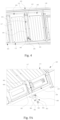
- Fig. 4 is a perspective view of an embodiment in which a collecting device 201 and a weighing device 202 in the system 300 shown in Fig. 2 are mounted in a reflow oven 100.
- the cooling zone 103 of the reflow oven 100 comprises a first cooling sub-zone 104 and a second cooling sub-zone 105.
- the first cooling sub-zone 104 is adjacent to the high temperature zone 102.
- the high temperature zone 102, the first cooling sub-zone 104 and the second cooling sub-zone 105 are disposed in sequence along a conveying direction of a workpiece in the reflow oven 100.
- the workpiece passes through the high temperature zone 102, the first cooling sub-zone 104 and the second cooling sub-zone 105 in sequence when conveyed in the reflow oven 100.
- the first cooling sub-zone 104 and the second cooling sub-zone 105 each include a lower reflow oven chamber device 111, which has an upper surface 117.
- the reflow oven chamber device 111 is mounted to a frame 118 of the reflow oven 100.
- An elongated cavity 119 is provided between the lower reflow oven chamber device 111 in the first cooling sub-zone 104 and the lower reflow oven chamber device 111 in the second cooling sub-zone 105, and is formed by a housing with an upper portion provided with an opening.
- the housing comprises a bottom portion 120, a front side (not visible in Fig. 4 ), a rear side 121, a left side (not visible in Fig. 4 ), and a right side 122.
- Part (e.g., a plate structure) of the frame 118 forms the bottom portion 120, the front side and the rear side 121 of the housing, and a right wall of the lower reflow oven chamber device 111 in the first cooling sub-zone 104 and a left wall of the lower reflow oven chamber device 111 in the second cooling sub-zone 105 respectively form the left side and the right side 122 of the housing.
- the collecting device 201 is mounted on the weighing device 202.
- the weighing device 202 is mounted to a bottom portion 120 of the cavity 119.
- the weighing device 202 is mounted to the bottom portion 120 of the cavity 119 by means of a fastener, such as a screw.
- the weighing device 202 is mounted to the bottom portion 120 of the cavity 119 by other suitable means.
- the contaminants are also condensed on the collecting surface 601 of the collecting device 201 (see Fig. 6B ).
- the collecting surface 601 is configured to enable the contaminants to be adhered thereto.
- the collecting device 201 collects the contaminants adhered (condensed) thereto by means of the collecting surface 601.
- the weighing device 202 weighs the collecting device 201 to obtain weight information thereof. When the collecting device 201 collects no contaminants, the weighing device 202 obtains the initial weight information of the collecting device 201. When the collecting device 201 has collected contaminants, the weighing device 202 obtains the sum of the weight information of the collecting device 201 and the weight information of the collected contaminants.
- both the collecting device 201 and the weighing device 202 are mounted at a position in the reflow oven 100 during obtaining of the historical data, at which position contaminant weight threshold obtained is used by the control device 203 to determine whether the reflow oven 100 needs to be cleaned.
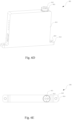
- Fig. 5A is a perspective view of another embodiment in which a collecting device 201 and a weighing device 202 in the system 300 shown in Fig. 2 are mounted in a reflow oven 100
- Fig. 5B is a partial enlarged view of Fig. 5A .
- the weighing device 202 is mounted outside the cooling zone 103, and the collecting device 201 is mounted on the weighing device 202.
- a bottom end 605 of the collecting device 201 is mounted to the weighing device 202.
- a main body portion 604 of the collecting device 201 extends through the frame 118 into the cooling zone 103, such that the collecting surface 601 of the collecting device 201 is disposed in the cooling zone 103.
- the cooling zone 103 when contaminants are condensed on the surface 117 of the lower reflow oven chamber device 111, the contaminants are also condensed on the collecting surface 601 of the collecting device 201.
- the weighing device 202 is mounted to the reflow oven 100 via a mounting structure 501.
- the mounting structure 501 is formed by a plate structure, which is bent into a Z shape and comprises an upper end 502 and a lower end 503.
- the upper end 502 is fixed to the frame 118, and the weighing device 202 is mounted on the lower end 503.
- the weighing device 202 is fixed to the lower end 503 of the mounting structure 501 by means of a fastener 504.
- the mounting structure 501 is of a rigid structure, and is configured to support the weighing device 202.
- the mounting structure 501 comprises other suitable structures, to mount the weighing device 202 to the reflow oven 100.
- both the collecting device 201 and the weighing device 202 are mounted at a position in the reflow oven 100 during obtaining of the historical data, at which position contaminant weight threshold obtained is used by the control device 203 to determine whether the reflow oven 100 needs to be cleaned.
- Fig. 6A is a perspective view of a collecting device 201 and a weighing device 202 in the system 300 shown in Fig. 2 when mounted together
- Fig. 6B is a perspective view of the collecting device 201 shown in Fig. 6A
- Fig. 6C is a bottom view of Fig. 6B
- Fig. 6D is a perspective view of the weighing device 202 shown in Fig. 6A
- Fig. 6E is a top view of Fig. 6D .
- the collecting device 201 is mounted on the weighing device 202.
- the weighing device 202 weighs the collecting device 201 thereon to obtain weight information of the collecting device.
- the collecting device 201 comprises a collecting surface 601, a collecting recess 602, a main body portion 604, and a collection mounting portion 603.
- the collecting surface 601 enables the contaminants to be adhered thereto, and is configured to collect the contaminants adhered thereto.
- the collecting surface 601 is a tapered surface for reducing impact of a gas flow discharged from the upper reflow oven chamber device 111 on the weighing device 202 during the weighing of the contaminants on the collecting surface 601, so that the weighing is more accurate.
- the collecting recess 602 is configured to collect the contaminants flowing from the collecting surface 601.
- the collecting recess 602 is communicated with a bottom portion of the collecting surface 601 to collect the contaminants flowing downwardly from the collecting surface 601, so as to prevent the contaminants collected on the collecting surface 601 from flowing out of the collecting device 201, which otherwise results in inaccurate collection of the contaminants by the collecting device 201.
- the collecting recess 602 collects the contaminants flowing from the collecting surface 601, so that the collecting device 201 can collect the contaminants more accurately.
- a recess portion of the collecting recess 602 is disposed toward the collecting surface 601.
- the main body portion 604 is substantially cylindrical.
- the main body portion 604 extends downwardly from the collecting recess 602 to the bottom end 605 of the collecting device 201.
- the collection mounting portion 603 is disposed at the bottom end 605 of the collecting device 201.
- the collection mounting portion 603 is configured to be removably mounted to the weighing device 202, for example, to a first mounting portion 611 of the weighing device 202 (see Figs. 6D-6E ), such that the collecting device 201 is mounted to the weighing device 202.
- the collection mounting portion 603 is cylindrical.
- the collecting device 201 comprises two collection mounting portions 603. In other embodiments, the collecting device 201 comprises a different number of collection mounting portions 603.
- the weighing device 202 comprises the first mounting portion 611, a main body portion 613, and a second mounting portion 614.
- the first mounting portion 611 is configured to enable the collecting device 201 to be mounted to the weighing device 202.
- the first mounting portion 611 comprises a receiving hole 612, which is configured to receive the collection mounting portion 603 of the collecting device 201.
- the first mounting portion 611 is substantially cylindrical, and the receiving hole 612 is cylindrical.
- the collection mounting portion 603 of the collecting device 201 is inserted into the receiving hole 612 of the weighing device 202, such that the collecting device 201 is mounted to the weighing device 202.
- the inner diameter of the receiving hole 612 is slightly greater than the outer diameter of the collection mounting portion 603, such that the collection mounting portion 603 of the collecting device 201 can be inserted into the receiving hole 612 of the weighing device 202.
- the first mounting portion 611 comprises other suitable structures
- the receiving hole 612 comprises other suitable structures.
- the first mounting portion 611 is mounted on the main body portion 613.
- a weighing mechanism is provided in the main body portion 613, and is configured to weigh an object provided thereon.
- the second mounting portion 614 is configured to enable the weighing device 202 to be mounted to the reflow oven 100.
- the second mounting portion 614 extends from the main body portion 613, for example, extends outwardly from a bottom portion of a side surface of the main body portion 613.
- the second mounting portion 614 is a flange.
- the second mounting portion 614 comprises an opening 615.
- a fastener such as a screw, can pass through the opening 615 of the weighing device 202 to fasten the weighing device 202 to the reflow oven 100.
- the weighing device 202 is a precision balance.
- the precision balance has a measurement range of 300 g and a resolution accuracy of 5 mg.
- the weighing device 202 comprises other suitable devices.
- Fig. 7 is a flowchart of a method 700 for determining whether to clean a reflow oven 100 according to the present disclosure.
- step 702 the method 700 for determining whether to clean a reflow oven 100 starts. Then, the process proceeds from step 702 to step 710.
- the collecting device 201 is arranged in a first cooling sub-zone 104 of the cooling zone 103, and the contaminants adhered to the collecting device are collected by the collecting device 201.
- the collecting device 201 is arranged in a spacing between the first cooling sub-zone 104 of the cooling zone 103 and a second cooling sub-zone 105 of the cooling zone 103, and the contaminants adhered to the collecting device are collected by the collecting device 201.
- the high temperature zone 102, the first cooling sub-zone 104 and the second cooling sub-zone 105 of the reflow oven 100 are disposed in sequence along a conveying direction of a workpiece in the reflow oven 100. Then, the process proceeds from step 710 to step 712.
- the collecting device 201 is weighed to obtain weight information of the collecting device 201.
- Weighing the collecting device 201 to obtain weight information of the collecting device 201 comprises weighing the collecting device 201 without collected contaminants to obtain the initial weight information of the collecting device 201, and weighing the collecting device 201 with collected contaminants to obtain the weight information of the collecting device 201. Then, the process proceeds from step 712 to step 714.
- step 714 it is determined whether the reflow oven 100 needs to be cleaned based on the weight information of the collecting device 201. Determining whether the reflow oven 100 needs to be cleaned based on the weight information of the collecting device 201 comprises determining whether the reflow oven 100 needs to be cleaned based on whether the weight information of the collecting device 201 with collected contaminants reaches a collecting device weight threshold, and determining whether the reflow oven 100 needs to be cleaned based on whether the weight information of the contaminants collected by the collecting device 201 reaches a contaminant weight threshold. Determining whether the reflow oven 100 needs to be cleaned comprises determining that the reflow oven 100 needs to be cleaned after a predetermined period of time, and determining that the reflow oven 100 needs to be cleaned immediately. Then, the process proceeds from step 714 to step 716.
- an indication indicative of whether the reflow oven 100 needs to be cleaned is generated based on the determination. Generating an indication indicative of whether the reflow oven 100 needs to be cleaned comprises generating a visual indication or an audible indication indicative of whether the reflow oven 100 needs to be cleaned. Then, the process proceeds from step 716 to step 718, and the method 700 for determining cleaning of a reflow oven 100 ends.
- Determining whether the reflow oven 100 needs to be cleaned at step 714 comprises determining whether the weight information of the collecting device 201 with collected contaminants reaches the collecting device weight threshold. If the weight information of the collecting device 201 with collected contaminants reaches the collecting device weight threshold, it is determined that the reflow oven 100 needs to be cleaned, otherwise, it is determined that the reflow oven 100 does not need to be cleaned. In another embodiment, determining whether the reflow oven 100 needs to be cleaned at step 714 comprises determining whether the weight information of the contaminants collected by the collecting device 201 reaches the contaminant weight threshold.
- Figs. 8A-B show specific operations of step 714.
- Fig. 8A is a detailed flowchart of an embodiment of step 714 shown in Fig. 7
- Fig. 8B is a detailed flowchart of another embodiment of step 714 shown in Fig. 7 .
- the process proceeds from step 712 in Fig. 7 to step 802.
- the collecting device weight threshold is obtained based on the initial weight information of the collecting device 201 without collected contaminants and a contaminant weight threshold.
- the initial weight information of the collecting device 201 without collected contaminants is obtained, and a sum of the initial weight information of the collecting device 201 and the contaminant weight threshold is obtained as the collecting device weight threshold.
- the initial weight information is either one of the following: before each determination of whether the reflow oven 100 needs to be cleaned, weight information of the collecting device 201 when initially mounted to the reflow oven 100 or weight information of the collecting device 201 when mounted to the reflow oven 100 after the cleaning is completed, at which time the collecting device 201 collects no contaminants.
- the process proceeds from step 802 to step 804.
- step 804 the weight information of the collecting device 201 with collected contaminants is compared with the collecting device weight threshold. Then, the process proceeds from step 804 to step 806.
- step 806 it is determined whether the weight information of the collecting device 201 with collected contaminants reaches the collecting device weight threshold. If the weight information of the collecting device 201 with collected contaminants reaches the collecting device weight threshold, the process proceeds to step 808. Otherwise, the process proceeds to step 804, at which updated weight information of the collecting device 201 with collected contaminants is compared with the collecting device weight threshold to determine whether the reflow oven 100 needs to be cleaned.
- step 808 it is determined that the reflow oven 100 needs to be cleaned, and a control signal for cleaning the reflow oven 100 is output. Then, the process proceeds from step 808 to step 716 in Fig. 7 .
- step 812 proceeds from step 712 in Fig. 7 to step 812.
- the weight information of the contaminants collected by the collecting device 201 is obtained based on the initial weight information of the collecting device 201 without collected contaminants and the weight information of the collecting device 201 with collected contaminants.
- the initial weight information of the collecting device 201 without collected contaminants is obtained, the weight information of the collecting device 201 with collected contaminants is obtained, and a difference between the initial weight information of the collecting device 201 and the weight information of the collecting device 201 with collected contaminants is obtained as the weight information of the contaminants collected by the collecting device 201.
- the initial weight information is either one of the following: before each determination of whether the reflow oven 100 needs to be cleaned, weight information of the collecting device 201 when initially mounted to the reflow oven 100 or weight information of the collecting device 201 mounted to the reflow oven 100 after the cleaning is completed, at which time the collecting device 201 collects no contaminants. Then, the process proceeds from step 812 to step 814.
- step 814 the weight information of the contaminants collected by the collecting device 201 is compared with a contaminant weight threshold. Then, the process proceeds from step 814 to step 816.
- step 816 it is determined whether the weight information of the contaminants collected by the collecting device 201 reaches the contaminant weight threshold. If the weight information of the contaminants collected by the collecting device 201 reaches the contaminant weight threshold, the process proceeds to step 818. Otherwise, the process proceeds to step 814, at which updated weight information of the contaminants collected by the collecting device 201 is compared with the contaminant weight threshold to determine whether the reflow oven 100 needs to be cleaned.
- step 818 it is determined that the reflow oven 100 needs to be cleaned, and a control signal for cleaning the reflow oven 100 is output. Then, the process proceeds from step 818 to step 716 in Fig. 7 .
- the contaminant weight threshold is obtained by means of historical data.
- the control device 203 obtains a weight value of the contaminants collected by the collecting device 201 when the reflow oven 100 needs to be cleaned. More specifically, the weighing device 202 weighs the collecting device 201 without collected contaminants to obtain the initial weight information of the collecting device 201, and weighs the collecting device 201 with collected contaminants to obtain contamination weight information of the collecting device 201 when the reflow oven 100 needs to be cleaned.
- the control device 203 obtains these weight values of the collecting device 201 and processes these weight values, to obtain the weight value of the contaminants collected by the collecting device 201 when the reflow oven 100 needs to be cleaned, and uses the weight value as the contaminant weight threshold.
- the control device 203 obtains the contaminant weight threshold by other suitable means.
- Fig. 9 is a block diagram of the control device 203 shown in Figs. 3A-3B .
- the control device 203 comprises a bus 901, a processor 902, a memory 903, an input interface 904, and an output interface 905.
- the processor 902, the memory 903, the input interface 904 and the output interface 905 are connected to the bus 901.
- the processor 902 may read programs (or instructions) from the memory 903 and execute the programs (or the instructions) to process data and/or control each component of the reflow oven 100.
- the processor 902 may further write data or programs (or instructions) into the memory 903.
- the memory 903 may store the programs (instructions) or the data. By executing the instructions in the memory 903, the processor 902 may control the memory 903, the input interface 904, and the output interface 905.
- the input interface 904 is configured to receive weight information from the weighing device 202 by means of a connecting line 302.
- the input interface 904 is further configured to convert the received weight information into a signal recognizable by the processor 902 and output the signal to the processor 902.
- the processor 902 is configured to process (e.g., calculate and determine) the received signal to output a control signal that the reflow oven 100 needs to be cleaned.
- the output interface 905 is configured to receive the control signal from the processor 902, convert the control signal into an output signal suitable for an indicating device 204, and send the output signal to the indicating device 204 by means of a connecting line 303, such that the indicating device 204 generates an indication that the reflow oven 100 needs to be cleaned, which, for example, comprises an indication that the reflow oven 100 needs to be cleaned after a predetermined period of time, and an indication that the reflow oven 100 needs to be cleaned immediately.
Landscapes
- Engineering & Computer Science (AREA)
- Mechanical Engineering (AREA)
- General Engineering & Computer Science (AREA)
- Manufacturing & Machinery (AREA)
- Microelectronics & Electronic Packaging (AREA)
- Electric Connection Of Electric Components To Printed Circuits (AREA)
- Electric Vacuum Cleaner (AREA)
Abstract
The present disclosure provides a system and method for determining whether to clean a reflow oven. The system comprises a collecting device, a weighing device, and a control device. The collecting device is disposed in a cooling zone, and is configured to collect contaminants. The collecting device is mounted on the weighing device. The weighing device is configured to weigh the collecting device to obtain weight information of the collecting device. The control device is configured to determine whether the reflow oven needs to be cleaned based on the weight information of the collecting device. The method comprises collecting contaminants in a cooling zone by a collecting device, weighing the collecting device to obtain weight information of the collecting device, and determining whether the reflow oven needs to be cleaned based on the weight information of the collecting device. According to the present disclosure, based on determining that the reflow oven needs to be cleaned, a user can be prompted to clean the reflow oven at an appropriate time, thereby improving the production efficiency of the reflow oven and reducing unnecessary downtime.
Description
- The present disclosure relates to a reflow oven, and in particular, to a system and method for determining whether to clean a reflow oven.
- During the manufacture of printed circuit boards, electronic elements are mounted on the circuit boards generally by using a process known as "reflow soldering". In a typical reflow soldering process, solder paste (e.g., tin solder paste) is deposited onto selected areas on a circuit board, and wires of one or more electronic elements are imbedded into the deposited solder paste. The circuit board then passes through a reflow oven. In the reflow oven, the solder paste reflows in a high temperature zone of a hearth of the reflow oven (i.e., being heated to a melting or reflow temperature) and is then cooled in a cooling zone of the hearth to electrically and mechanically connect the wires of the electronic elements to the circuit board. As used herein, the term "circuit board" or "printed circuit board (PCB)" includes a substrate assembly of any type of electronic elements, for example, including a wafer substrate. In the reflow oven, air or a substantially inert gas (e.g., nitrogen) is generally used as a working gas, and different working gases are used for circuit boards having different process requirements. The hearth of the reflow oven is full of the working gas, and the circuit board is soldered under the working gas while being conveyed through the hearth by a conveying device.
- Tin solder paste includes not only a solder, but also a soldering flux which promotes wetting of the solder and provides a good solder j oint. Other additives such as solvents and catalysts may also be included. After the tin paste is printed on a circuit board, the circuit board is conveyed on a conveyor to pass through a plurality of high temperature zones of a hearth of a reflow oven. Heat in the high temperature zones melts the tin solder paste, and organic compounds containing volatile organic compounds (VOCs), mainly including a soldering flux, are vaporized into vapor, thereby forming "contaminants". These contaminants are mixed with a working gas in the high temperature zones to form a waste gas. The accumulation of these contaminants in the hearth of the reflow oven may cause some problems. For example, when the circuit board is conveyed from the high temperature zones to a cooling zone, the contaminants also flow to the cooling zone, and the contaminants will be condensed into a liquid and/or a solid and drip onto the circuit board after being cooled in the cooling zone, thus contaminating the circuit board. As a result, a subsequent cleaning step has to be performed. Moreover, condensates may also drip onto subsequent circuit boards; consequently, elements on the circuit boards may be damaged, or the contaminated circuit boards have to be cleaned in subsequent steps.
- The inventors have found that in the prior art, the reflow oven is cleaned by pre-arranged maintenance. However, the pre-arranged maintenance may be too early or too late, resulting in undesired downtime, thereby lowering the production efficiency.
- In order to solve the above problems, the present disclosure provides a system and method for determining whether to clean a reflow oven, in which contaminants are collected in a cooling zone by a collecting device, the collecting device with collected contaminants is weighed to obtain weight information of the collecting device, and whether the reflow oven needs to be cleaned is determined based on the weight information. According to the present disclosure, when it is determined that the reflow oven needs to be cleaned, a user can be prompted to clean and maintain the reflow oven at a reasonable time, thereby improving the production efficiency and reducing undesirable downtime.
- According to a first aspect of the present disclosure, the present disclosure provides a system for determining whether to clean a reflow oven. The reflow oven comprises a high temperature zone and a cooling zone. The system comprises a collecting device, a weighing device, and a control device. The collecting device is disposed in the cooling zone, and is configured to collect contaminants. The collecting device is mounted on the weighing device. The weighing device is configured to weigh the collecting device to obtain weight information of the collecting device. The control device is configured to determine whether the reflow oven needs to be cleaned based on the weight information of the collecting device.
- According to the first aspect of the present disclosure, the collecting device is disposed in a first cooling sub-zone of the cooling zone, or is disposed in an intermediate zone between the first cooling sub-zone of the cooling zone and a second cooling sub-zone of the cooling zone. The high temperature zone, the first cooling sub-zone and the second cooling sub-zone are disposed in sequence along a conveying direction of a workpiece in the reflow oven.
- According to the first aspect of the present disclosure, the weighing device is disposed inside or outside the cooling zone.
- According to the first aspect of the present disclosure, the collecting device comprises a collecting surface and a collecting recess. The collecting surface is configured to enable the contaminants to be adhered thereto. The collecting recess is communicated with the collecting surface, and is configured to collect the contaminants flowing from the collecting surface. The collecting surface is a tapered surface.
- According to the first aspect of the present disclosure, the collecting surface of the collecting device is configured to have the same material as that of the surface of a reflow oven chamber device in the cooling zone, such that the collecting surface of the collecting device allows the contaminants to be adhered with the same adhesion property as that of the surface of the reflow oven chamber device.
- According to the first aspect of the present disclosure, the weighing device is a precision balance.
- According to the first aspect of the present disclosure, the control device is configured to compare the weight information of the collecting device with collected contaminants with a collecting device weight threshold, and determine that the reflow oven needs to be cleaned if the weight information of the collecting device with collected contaminants reaches the collecting device weight threshold. The control device is configured to compare weight information of the contaminants collected by the collecting device with a contaminant weight threshold, and determine that the reflow oven needs to be cleaned if the weight information of the contaminants collected by the collecting device reaches the contaminant weight threshold.
- According to the first aspect of the present disclosure, the control device is further configured to determine that the reflow oven needs to be cleaned after a predetermined period of time based on the weight information of the collecting device, or to determine that the reflow oven needs to be cleaned immediately based on the weight information of the collecting device.
- According to the first aspect of the present disclosure, the control device is a controller of the reflow oven or different from the controller of the reflow oven.
- According to the first aspect of the present disclosure, the system further comprises an indicating device. The indicating device is configured to generate an indication indicative of whether the reflow oven needs to be cleaned based on a signal received from the control device. The indication comprises a visual indication or an audible indication.
- According to a second aspect of the present disclosure, the present disclosure provides a method for determining whether to clean a reflow oven. The reflow oven comprises a high temperature zone and a cooling zone. The method comprises: collecting contaminants in the cooling zone by a collecting device, weighing the collecting device to obtain weight information of the collecting device, and determining whether the reflow oven needs to be cleaned based on the weight information of the collecting device.
- According to the second aspect of the present disclosure, determining whether the reflow oven needs to be cleaned based on the weight information of the collecting device comprises: comparing the weight information of the collecting device with collected contaminants with a collecting device weight threshold; and determining that the reflow oven needs to be cleaned if the weight information of the collecting device with collected contaminants reaches the collecting device weight threshold.
- According to the second aspect of the present disclosure, the method further comprises: obtaining initial weight information of the collecting device without collected contaminants; and obtaining a sum of the initial weight information of the collecting device and a contaminant weight threshold as the collecting device weight threshold.
- According to the second aspect of the present disclosure, determining whether the reflow oven needs to be cleaned based on the weight information of the collecting device comprises: obtaining weight information of the contaminants collected by the collecting device based on the initial weight information of the collecting device without collected contaminants and weight information of the collecting device with collected contaminants; comparing the weight information of the contaminants collected by the collecting device with a contaminant weight threshold; and determining that the reflow oven needs to be cleaned if the weight information of the contaminants collected by the collecting device reaches the contaminant weight threshold.
- According to the second aspect of the present disclosure, the initial weight information of the collecting device without collected contaminants is obtained by: weighing the collecting device without collected contaminants after each cleaning of the reflow oven, so as to obtain the initial weight information of the collecting device.
- According to the second aspect of the present disclosure, collecting contaminants in the cooling zone by a collecting device comprises arranging the collecting device in a first cooling sub-zone of the cooling zone, and collecting, by the collecting device, the contaminants adhered thereto. Alternatively, collecting contaminants in the cooling zone by a collecting device comprises arranging the collecting device in an intermediate zone between the first cooling sub-zone of the cooling zone and a second cooling sub-zone of the cooling zone, and collecting, by the collecting device, the contaminants adhered thereto. The high temperature zone, the first cooling sub-zone and the second cooling sub-zone are disposed in sequence along a conveying direction of a workpiece in the reflow oven.
- According to the second aspect of the present disclosure, determining whether the reflow oven needs to be cleaned comprises: determining that the reflow oven needs to be cleaned after a predetermined period of time; and determining that the reflow oven needs to be cleaned immediately.
- According to the second aspect of the present disclosure, the method further comprises generating an indication indicative of whether the reflow oven needs to be cleaned based on the determination. Generating an indication indicative of whether the reflow oven needs to be cleaned comprises: generating a visual indication or an audible indication indicative of whether the reflow oven needs to be cleaned.
- According to a third aspect of the present disclosure, the present disclosure provides a reflow oven, which comprises a system for determining whether to clean a reflow oven as described above.
- According to the third aspect of the present disclosure, the present disclosure provides a reflow oven for implementing a method described above.
- The accompanying drawings are not drawn to scale. In the accompanying drawings, each identical or nearly identical component denoted in different figures is denoted by the same reference number. For the sake of clarity, not every component may be labeled in every figure. In the figures:
-
Fig. 1A is a perspective view of a reflow oven according to the present disclosure; -
Fig. 1B is a perspective view of the reflow oven shown inFig. 1A with a housing removed; -
Fig. 1C is a perspective view of the reflow oven shown inFig. 1B in an open state; -
Fig. 2 is a perspective view of a system for determining whether to clean a reflow oven mounted on a part of the reflow oven according to an embodiment of the present disclosure; -
Fig. 3A is a block diagram of a system for determining whether to clean a reflow oven according to an embodiment of the present disclosure; -
Fig. 3B is a block diagram of a system for determining cleaning of a reflow oven according to another embodiment of the present disclosure; -
Fig. 4 is a perspective view of an embodiment in which a collecting device and a weighing device of the system shown inFig. 2 are mounted in a reflow oven; -
Fig. 5A is a perspective view of another embodiment in which a collecting device and a weighing device of the system shown inFig. 2 are mounted in a reflow oven; -
Fig. 5B is a partial enlarged view ofFig. 5A ; -
Fig. 6A is a perspective view of a collecting device and a weighing device of the system shown inFig. 2 when mounted together; -
Fig. 6B is a perspective view of the collecting device shown inFig. 6A ; -
Fig. 6C is a bottom view ofFig. 6B ; -
Fig. 6D is a perspective view of the weighing device shown inFig. 6A ; -
Fig. 6E is a top view ofFig. 6D ; -
Fig. 7 is a flowchart of a method for determining whether to clean a reflow oven according to the present disclosure; -
Fig. 8A is a detailed flowchart of an embodiment ofstep 714 shown inFig. 7 ; -
Fig. 8B is a detailed flowchart of another embodiment ofstep 714 shown inFig. 7 ; and -
Fig. 9 is a block diagram of a control device shown inFigs. 3A-3B . - Various specific embodiments of the present disclosure are described below with reference to the drawings which constitute part of this specification. It should be understood that although the terms indicating directions, such as "front", "rear", "upper", "lower", "left" and "right" are used in the present disclosure to describe structural parts and elements in various examples of the present disclosure, these terms are used herein only for ease of description and are determined based on the exemplary orientation as shown in the drawings. Since the arrangements in the embodiments disclosed in the present disclosure may be in various directions, these terms indicating directions are only illustrative and should not be considered as limitations.
-
Fig. 1A is a perspective view of areflow oven 100 according to the present disclosure,Fig. 1B is a perspective view of thereflow oven 100 shown inFig. 1A with ahousing 101 removed, andFig. 1C is a perspective view of thereflow oven 100 shown inFig. 1B in an open state, to clearly show various components of thereflow oven 100 and a relationship between the various components. - As shown in
Fig. 1A , thereflow oven 100 comprises ahousing 101, and various components of thereflow oven 100 are disposed in thehousing 101. As shown inFigs. 1B-1C , thereflow oven 100 compriseshigh temperature zones 102 and coolingzones 103. Thereflow oven 100 comprises areflow oven chamber 110 configured to perform high-temperature treatment and then cooling treatment on a workpiece (e.g., a circuit board) (not shown) passing therethrough. Thereflow oven chamber 110 is provided with a plurality ofhigh temperature zones 102 and a plurality of coolingzones 103. Thereflow oven 100 further comprises a plurality of reflowoven chamber devices 111, which are disposed above and/or below thereflow oven chamber 110. Each reflowoven chamber device 111 is configured to deliver a gas flow to thereflow oven chamber 110 to process a workpiece in thereflow oven chamber 110. Reflowoven chamber devices 111 in thehigh temperature zones 102 deliver a hot gas flow to thereflow oven chamber 110 to perform high-temperature treatment on the workpiece. Reflowoven chamber devices 111 in thecooling zones 103 deliver a cold gas flow or a normal-temperature gas flow (e.g., an air flow in an external environment) to thereflow oven chamber 110 to cool the workpiece. Upper reflowoven chamber devices 111 are disposed above thereflow oven chamber 110, and lower reflowoven chamber devices 111 are disposed below thereflow oven chamber 110. Each upper reflowoven chamber device 111 is configured to deliver a gas flow to thereflow oven chamber 110 through a through hole (not shown) in abottom surface 124 of the upper reflow oven chamber device. Each lower reflowoven chamber device 111 is configured to deliver a gas flow to thereflow oven chamber 110 through a throughhole 126 in atop surface 125 of the lower reflow oven chamber device. -
Fig. 2 is a perspective view of asystem 300 for determining whether to clean areflow oven 100 mounted on a part of thereflow oven 100 according to an embodiment of the present disclosure, to clearly show various components of thesystem 300, a relationship between the various components, and mounting positions of these components. -
Fig. 2 shows a part of thereflow oven 100 that comprises a plurality of lower reflowoven chamber devices 111, above which areflow oven chamber 110 is provided. This part of thereflow oven 100 comprises ahigh temperature zone 102 and acooling zone 103. Thesystem 300 is mounted to this part of thereflow oven 100. Thesystem 300 comprises acollecting device 201, a weighingdevice 202, acontrol device 203, and an indicatingdevice 204. - As shown in
Fig. 2 , the collectingdevice 201 is mounted in thecooling zone 103 of thereflow oven 100, and is configured to collect contaminants. During normal operation of thereflow oven 100, a workpiece (e.g., a circuit board) is conveyed through thereflow oven chamber 110 of thereflow oven 100 so as to be processed. Vapor contaminants evaporated from thehigh temperature zone 102 are condensed on a surface of the reflowoven chamber device 111 and a surface of thecollecting device 201 after reaching thecooling zone 103. During the normal operation of thereflow oven 100, the collectingdevice 201 collects contaminants during the same period of time as the contaminants condensed on the surface of the reflowoven chamber device 111, so that the contaminants collected by the collectingdevice 201 can reflect a degree of contamination in thereflow oven 100. While contaminants are adhered (condensed) to the surface of the reflowoven chamber device 111, the contaminants are also adhered (condensed) to thecollecting device 201, and thus the contaminants on the collecting device are collected. A collectingsurface 601 of thecollecting device 201 is configured to have the same material as that of asurface 125 of the reflow oven chamber device 111 (i.e., thetop surface 125 of the lower reflow oven chamber device 111) in thecooling zone 103, such that the collectingsurface 601 of thecollecting device 201 allows the contaminants to be adhered with the same adhesion property as that of thesurface 125 of the reflowoven chamber device 111. This configuration of thecollecting device 201 facilitates thesystem 300 to accurately determine whether to clean thereflow oven 100. When thereflow oven 100 is initially mounted, the collectingdevice 201 is mounted in thereflow oven 100. After each cleaning of thereflow oven 100 is completed, the collectingdevice 201 is also cleaned accordingly, and is mounted in thereflow oven 100 after the cleaning is completed, so as to collect contaminants during the normal operation of thereflow oven 100. - The collecting
device 201 is mounted on the weighingdevice 202. In this embodiment, the weighingdevice 202 is mounted in thecooling zone 103 of thereflow oven 100. In other embodiments, the weighingdevice 202 is mounted outside thecooling zone 103 of the reflow oven 100 (seeFigs. 5A-5B ). The weighingdevice 202 is configured to weigh thecollecting device 201 to obtain weight information of thecollecting device 201. The weighingdevice 202 weighs the collectingdevice 201 with collected contaminants to obtain a sum of the weight information of thecollecting device 201 and weight information of the collected contaminants. The weight information of thecollecting device 201 with collected contaminants can reflect the degree of contamination in thereflow oven 100. The weighingdevice 202 is further configured to weigh thecollecting device 201 without collected contaminants, to obtain initial weight information of thecollecting device 201. - The
control device 203 is connected to the weighingdevice 202, for example, via a connecting line (not shown). Thecontrol device 203 is configured to obtain the weight information of thecollecting device 201 from the weighingdevice 202 in real time. Thecontrol device 203 is further configured to determine whether thereflow oven 100 needs to be cleaned based on the weight information of thecollecting device 201 obtained from the weighingdevice 202. Thecontrol device 203 is further configured to output a control signal on whether thereflow oven 100 needs to be cleaned. For example, when it is determined that thereflow oven 100 needs to be cleaned, thecontrol device 203 outputs a control signal indicating that thereflow oven 100 needs to be cleaned. Determining whether thereflow oven 100 needs to be cleaned comprises determining that thereflow oven 100 needs to be cleaned after a predetermined period of time, and determining that thereflow oven 100 needs to be cleaned immediately. - The indicating
device 204 is connected to thecontrol device 203. The indicatingdevice 204 is configured to receive the control signal from thecontrol device 203, and generate an indication indicative of whether thereflow oven 100 needs to be cleaned based on this control signal. The indication comprises a visual indication or an audible indication. In this embodiment, the indicatingdevice 204 is an indicator lamp. In other embodiments, the indicatingdevice 204 comprises a display, or other suitable indicating devices or structures. - When determining whether the
reflow oven 100 needs to be cleaned, thecontrol device 203 compares the weight information of thecollecting device 201 with collected contaminants with a collecting device weight threshold. When the weight information of thecollecting device 201 with collected contaminants reaches the collecting device weight threshold, thecontrol device 203 determines that thereflow oven 100 needs to be cleaned, otherwise, the control device determines that thereflow oven 100 does not need to be cleaned. In an embodiment, thecontrol device 203 obtains a sum of the initial weight information of thecollecting device 201 without collected contaminants and a contaminant weight threshold as the collecting device weight threshold. - In another embodiment, when determining whether the
reflow oven 100 needs to be cleaned, thecontrol device 203 compares the weight information of the contaminants collected by the collectingdevice 201 with the contaminant weight threshold. When the weight information of the contaminants collected by the collectingdevice 201 reaches the contaminant weight threshold, thecontrol device 203 determines that thereflow oven 100 needs to be cleaned, otherwise, the control device determines that thereflow oven 100 does not need to be cleaned. Thecontrol device 203 obtains the weight information of the contaminants collected by the collectingdevice 201 based on the initial weight information of thecollecting device 201 without collected contaminants and the weight information of thecollecting device 201 with collected contaminants, for example, based on a difference therebetween. In other embodiments, thecontrol device 203 determines whether thereflow oven 100 needs to be cleaned by other suitable means. - In an embodiment, the initial weight information is either one of the following: before each determination of whether the
reflow oven 100 needs to be cleaned, weight information of thecollecting device 201 when initially mounted to thereflow oven 100, or weight information of thecollecting device 201 when mounted to thereflow oven 100 after the cleaning is completed, at which time thecollecting device 201 collects no contaminants. - In an embodiment, the contaminant weight threshold is obtained by means of historical data. For example, during multiple practical operations performed by a user, the
control device 203 obtains a weight value of the contaminants collected by the collectingdevice 201 when thereflow oven 100 needs to be cleaned. More specifically, the weighingdevice 202 weighs the collectingdevice 201 without collected contaminants to obtain the initial weight information of thecollecting device 201, and weighs the collectingdevice 201 with collected contaminants to obtain contamination weight information of thecollecting device 201 when thereflow oven 100 needs to be cleaned. Thecontrol device 203 obtains these weight values of thecollecting device 201 and processes these weight values, to obtain the weight value of the contaminants collected by the collectingdevice 201 when thereflow oven 100 needs to be cleaned, and uses the weight value as the contaminant weight threshold. In other embodiments, thecontrol device 203 obtains the contaminant weight threshold by other suitable means. - In an embodiment, the
control device 203 is a controller of thereflow oven 100. In another embodiment, thecontrol device 203 is an additional control device, which is different from the controller of thereflow oven 100. In an embodiment, the indicatingdevice 204 is an indicating device of thereflow oven 100. In another embodiment, the indicatingdevice 204 is an additional indicating device, which is different from the indicating device of thereflow oven 100. - In another embodiment, the
system 300 comprises acollecting device 201, a weighingdevice 202 and acontrol device 203, and the structures and operations of these devices are the same as those of the same devices described above. -
Fig. 3A is a block diagram of asystem 300 for determining whether to clean areflow oven 100 according to an embodiment of the present disclosure, andFig. 3B is a block diagram of asystem 300 for determining whether to clean areflow oven 100 according to another embodiment of the present disclosure. - As shown in
Fig. 3A , in an embodiment, thesystem 300 for determining whether to clean areflow oven 100 comprises acollecting device 201, a weighingdevice 202, acontrol device 203, and an indicatingdevice 204. The collectingdevice 201 is mounted in thecooling zone 103 of the reflow oven 100 (seeFig. 2 ), and is configured to collect contaminants. The collectingdevice 201 is mounted on the weighingdevice 202. A connectingline 301 between the collectingdevice 201 and the weighingdevice 202 shown inFig. 3A denotes a physical connection. The weighingdevice 202 is configured to weigh thecollecting device 201 to obtain weight information of thecollecting device 201. Thecontrol device 203 is connected to the weighingdevice 202 via a connecting line 302 (e.g., a data line). Thecontrol device 203 is configured to receive the weight information of thecollecting device 201 from the weighingdevice 202 by means of the connectingline 302, and determine whether thereflow oven 100 needs to be cleaned based on the weight information. - When determining whether the
reflow oven 100 needs to be cleaned, thecontrol device 203 compares the weight information of thecollecting device 201 with collected contaminants with a collecting device weight threshold. When the weight information of thecollecting device 201 with collected contaminants reaches the collecting device weight threshold, thecontrol device 203 determines that thereflow oven 100 needs to be cleaned, otherwise, the control device determines that thereflow oven 100 does not need to be cleaned. In another embodiment, when determining whether thereflow oven 100 needs to be cleaned, thecontrol device 203 compares the weight information of the contaminants collected by the collectingdevice 201 with the contaminant weight threshold. When the weight information of the contaminants collected by the collectingdevice 201 reaches the contaminant weight threshold, thecontrol device 203 determines that thereflow oven 100 needs to be cleaned, otherwise, the control device determines that thereflow oven 100 does not need to be cleaned. In other embodiments, thecontrol device 203 determines whether thereflow oven 100 needs to be cleaned by other suitable means. Thecontrol device 203 is further configured to output a control signal on whether thereflow oven 100 needs to be cleaned. The indicatingdevice 204 is connected to thecontrol device 203 via a connectingline 303. The indicatingdevice 204 is configured to receive the control signal from thecontrol device 203 by means of the connectingline 303, and generate an indication indicative of whether thereflow oven 100 needs to be cleaned based on this control signal. - In another embodiment, the
system 300 comprises acollecting device 201, a weighingdevice 202 and acontrol device 203, and the structures and operations of these devices are the same as those of the same devices described above. - As shown in
Fig. 3B , thereflow oven 100 comprises asystem 300. Thesystem 300 inFig. 3B has the same structure as thesystem 300 inFig. 3A . -
Fig. 4 is a perspective view of an embodiment in which acollecting device 201 and a weighingdevice 202 in thesystem 300 shown inFig. 2 are mounted in areflow oven 100. - As shown in
Fig. 4 , thecooling zone 103 of thereflow oven 100 comprises afirst cooling sub-zone 104 and asecond cooling sub-zone 105. Thefirst cooling sub-zone 104 is adjacent to thehigh temperature zone 102. Thehigh temperature zone 102, thefirst cooling sub-zone 104 and thesecond cooling sub-zone 105 are disposed in sequence along a conveying direction of a workpiece in thereflow oven 100. The workpiece passes through thehigh temperature zone 102, thefirst cooling sub-zone 104 and thesecond cooling sub-zone 105 in sequence when conveyed in thereflow oven 100. Thefirst cooling sub-zone 104 and thesecond cooling sub-zone 105 each include a lower reflowoven chamber device 111, which has anupper surface 117. The reflowoven chamber device 111 is mounted to aframe 118 of thereflow oven 100. Anelongated cavity 119 is provided between the lower reflowoven chamber device 111 in thefirst cooling sub-zone 104 and the lower reflowoven chamber device 111 in thesecond cooling sub-zone 105, and is formed by a housing with an upper portion provided with an opening. The housing comprises abottom portion 120, a front side (not visible inFig. 4 ), arear side 121, a left side (not visible inFig. 4 ), and aright side 122. Part (e.g., a plate structure) of theframe 118 forms thebottom portion 120, the front side and therear side 121 of the housing, and a right wall of the lower reflowoven chamber device 111 in thefirst cooling sub-zone 104 and a left wall of the lower reflowoven chamber device 111 in thesecond cooling sub-zone 105 respectively form the left side and theright side 122 of the housing. - The collecting
device 201 is mounted on the weighingdevice 202. The weighingdevice 202 is mounted to abottom portion 120 of thecavity 119. In an embodiment, the weighingdevice 202 is mounted to thebottom portion 120 of thecavity 119 by means of a fastener, such as a screw. In other embodiments, the weighingdevice 202 is mounted to thebottom portion 120 of thecavity 119 by other suitable means. - In the
cooling zone 103, when contaminants are condensed on thesurface 117 of the lower reflowoven chamber device 111, the contaminants are also condensed on the collectingsurface 601 of the collecting device 201 (seeFig. 6B ). The collectingsurface 601 is configured to enable the contaminants to be adhered thereto. The collectingdevice 201 collects the contaminants adhered (condensed) thereto by means of the collectingsurface 601. The weighingdevice 202 weighs the collectingdevice 201 to obtain weight information thereof. When thecollecting device 201 collects no contaminants, the weighingdevice 202 obtains the initial weight information of thecollecting device 201. When thecollecting device 201 has collected contaminants, the weighingdevice 202 obtains the sum of the weight information of thecollecting device 201 and the weight information of the collected contaminants. - As shown in
Fig. 4 , when the contaminant weight threshold is obtained by means of historical data, both thecollecting device 201 and the weighingdevice 202 are mounted at a position in thereflow oven 100 during obtaining of the historical data, at which position contaminant weight threshold obtained is used by thecontrol device 203 to determine whether thereflow oven 100 needs to be cleaned. -
Fig. 5A is a perspective view of another embodiment in which acollecting device 201 and a weighingdevice 202 in thesystem 300 shown inFig. 2 are mounted in areflow oven 100, andFig. 5B is a partial enlarged view ofFig. 5A . - As shown in
Figs. 5A-5B , the weighingdevice 202 is mounted outside thecooling zone 103, and thecollecting device 201 is mounted on the weighingdevice 202. Abottom end 605 of thecollecting device 201 is mounted to the weighingdevice 202. Amain body portion 604 of thecollecting device 201 extends through theframe 118 into thecooling zone 103, such that the collectingsurface 601 of thecollecting device 201 is disposed in thecooling zone 103. In thecooling zone 103, when contaminants are condensed on thesurface 117 of the lower reflowoven chamber device 111, the contaminants are also condensed on the collectingsurface 601 of thecollecting device 201. - The weighing
device 202 is mounted to thereflow oven 100 via a mountingstructure 501. In this embodiment, the mountingstructure 501 is formed by a plate structure, which is bent into a Z shape and comprises anupper end 502 and alower end 503. Theupper end 502 is fixed to theframe 118, and the weighingdevice 202 is mounted on thelower end 503. The weighingdevice 202 is fixed to thelower end 503 of the mountingstructure 501 by means of afastener 504. The mountingstructure 501 is of a rigid structure, and is configured to support the weighingdevice 202. In other embodiments, the mountingstructure 501 comprises other suitable structures, to mount the weighingdevice 202 to thereflow oven 100. - As shown in
Fig. 5A-5B , when the contaminant weight threshold is obtained by means of historical data, both thecollecting device 201 and the weighingdevice 202 are mounted at a position in thereflow oven 100 during obtaining of the historical data, at which position contaminant weight threshold obtained is used by thecontrol device 203 to determine whether thereflow oven 100 needs to be cleaned. -
Fig. 6A is a perspective view of acollecting device 201 and a weighingdevice 202 in thesystem 300 shown inFig. 2 when mounted together,Fig. 6B is a perspective view of thecollecting device 201 shown inFig. 6A ,Fig. 6C is a bottom view ofFig. 6B ,Fig. 6D is a perspective view of the weighingdevice 202 shown inFig. 6A , andFig. 6E is a top view ofFig. 6D . - As shown in
Fig. 6A , the collectingdevice 201 is mounted on the weighingdevice 202. The weighingdevice 202 weighs the collectingdevice 201 thereon to obtain weight information of the collecting device. As shown inFigs. 6B-6C , the collectingdevice 201 comprises a collectingsurface 601, a collectingrecess 602, amain body portion 604, and acollection mounting portion 603. The collectingsurface 601 enables the contaminants to be adhered thereto, and is configured to collect the contaminants adhered thereto. The collectingsurface 601 is a tapered surface for reducing impact of a gas flow discharged from the upper reflowoven chamber device 111 on the weighingdevice 202 during the weighing of the contaminants on the collectingsurface 601, so that the weighing is more accurate. When excessive contaminants are collected on the collectingsurface 601, the contaminants will flow downwardly along the collectingsurface 601 to the collectingrecess 602. The collectingrecess 602 is configured to collect the contaminants flowing from the collectingsurface 601. The collectingrecess 602 is communicated with a bottom portion of the collectingsurface 601 to collect the contaminants flowing downwardly from the collectingsurface 601, so as to prevent the contaminants collected on the collectingsurface 601 from flowing out of thecollecting device 201, which otherwise results in inaccurate collection of the contaminants by the collectingdevice 201. The collectingrecess 602 collects the contaminants flowing from the collectingsurface 601, so that the collectingdevice 201 can collect the contaminants more accurately. A recess portion of the collectingrecess 602 is disposed toward the collectingsurface 601. - The
main body portion 604 is substantially cylindrical. Themain body portion 604 extends downwardly from the collectingrecess 602 to thebottom end 605 of thecollecting device 201. Thecollection mounting portion 603 is disposed at thebottom end 605 of thecollecting device 201. Thecollection mounting portion 603 is configured to be removably mounted to the weighingdevice 202, for example, to a first mountingportion 611 of the weighing device 202 (seeFigs. 6D-6E ), such that the collectingdevice 201 is mounted to the weighingdevice 202. Thecollection mounting portion 603 is cylindrical. In this embodiment, the collectingdevice 201 comprises twocollection mounting portions 603. In other embodiments, the collectingdevice 201 comprises a different number ofcollection mounting portions 603. - As shown in
Figs. 6D-6E , the weighingdevice 202 comprises the first mountingportion 611, amain body portion 613, and a second mountingportion 614. The first mountingportion 611 is configured to enable thecollecting device 201 to be mounted to the weighingdevice 202. The first mountingportion 611 comprises a receivinghole 612, which is configured to receive thecollection mounting portion 603 of thecollecting device 201. In this embodiment, the first mountingportion 611 is substantially cylindrical, and the receivinghole 612 is cylindrical. Thecollection mounting portion 603 of thecollecting device 201 is inserted into the receivinghole 612 of the weighingdevice 202, such that the collectingdevice 201 is mounted to the weighingdevice 202. The inner diameter of the receivinghole 612 is slightly greater than the outer diameter of thecollection mounting portion 603, such that thecollection mounting portion 603 of thecollecting device 201 can be inserted into the receivinghole 612 of the weighingdevice 202. In other embodiments, the first mountingportion 611 comprises other suitable structures, and the receivinghole 612 comprises other suitable structures. The first mountingportion 611 is mounted on themain body portion 613. A weighing mechanism is provided in themain body portion 613, and is configured to weigh an object provided thereon. Thesecond mounting portion 614 is configured to enable the weighingdevice 202 to be mounted to thereflow oven 100. Thesecond mounting portion 614 extends from themain body portion 613, for example, extends outwardly from a bottom portion of a side surface of themain body portion 613. In this embodiment, the second mountingportion 614 is a flange. Thesecond mounting portion 614 comprises anopening 615. A fastener, such as a screw, can pass through theopening 615 of the weighingdevice 202 to fasten the weighingdevice 202 to thereflow oven 100. In an embodiment, the weighingdevice 202 is a precision balance. In an embodiment, the precision balance has a measurement range of 300 g and a resolution accuracy of 5 mg. In other embodiments, the weighingdevice 202 comprises other suitable devices. -
Fig. 7 is a flowchart of amethod 700 for determining whether to clean areflow oven 100 according to the present disclosure. - As shown in
Fig. 7 , atstep 702, themethod 700 for determining whether to clean areflow oven 100 starts. Then, the process proceeds fromstep 702 to step 710. - At
step 710, contaminants are collected in thecooling zone 103 by acollecting device 201. In an embodiment, the collectingdevice 201 is arranged in afirst cooling sub-zone 104 of thecooling zone 103, and the contaminants adhered to the collecting device are collected by the collectingdevice 201. In another embodiment, the collectingdevice 201 is arranged in a spacing between thefirst cooling sub-zone 104 of thecooling zone 103 and asecond cooling sub-zone 105 of thecooling zone 103, and the contaminants adhered to the collecting device are collected by the collectingdevice 201. Thehigh temperature zone 102, thefirst cooling sub-zone 104 and thesecond cooling sub-zone 105 of thereflow oven 100 are disposed in sequence along a conveying direction of a workpiece in thereflow oven 100. Then, the process proceeds fromstep 710 to step 712. - At
step 712, the collectingdevice 201 is weighed to obtain weight information of thecollecting device 201. Weighing thecollecting device 201 to obtain weight information of thecollecting device 201 comprises weighing thecollecting device 201 without collected contaminants to obtain the initial weight information of thecollecting device 201, and weighing thecollecting device 201 with collected contaminants to obtain the weight information of thecollecting device 201. Then, the process proceeds fromstep 712 to step 714. - At
step 714, it is determined whether thereflow oven 100 needs to be cleaned based on the weight information of thecollecting device 201. Determining whether thereflow oven 100 needs to be cleaned based on the weight information of thecollecting device 201 comprises determining whether thereflow oven 100 needs to be cleaned based on whether the weight information of thecollecting device 201 with collected contaminants reaches a collecting device weight threshold, and determining whether thereflow oven 100 needs to be cleaned based on whether the weight information of the contaminants collected by the collectingdevice 201 reaches a contaminant weight threshold. Determining whether thereflow oven 100 needs to be cleaned comprises determining that thereflow oven 100 needs to be cleaned after a predetermined period of time, and determining that thereflow oven 100 needs to be cleaned immediately. Then, the process proceeds fromstep 714 to step 716. - At
step 716, an indication indicative of whether thereflow oven 100 needs to be cleaned is generated based on the determination. Generating an indication indicative of whether thereflow oven 100 needs to be cleaned comprises generating a visual indication or an audible indication indicative of whether thereflow oven 100 needs to be cleaned. Then, the process proceeds fromstep 716 to step 718, and themethod 700 for determining cleaning of areflow oven 100 ends. - Determining whether the
reflow oven 100 needs to be cleaned atstep 714 comprises determining whether the weight information of thecollecting device 201 with collected contaminants reaches the collecting device weight threshold. If the weight information of thecollecting device 201 with collected contaminants reaches the collecting device weight threshold, it is determined that thereflow oven 100 needs to be cleaned, otherwise, it is determined that thereflow oven 100 does not need to be cleaned. In another embodiment, determining whether thereflow oven 100 needs to be cleaned atstep 714 comprises determining whether the weight information of the contaminants collected by the collectingdevice 201 reaches the contaminant weight threshold. If the weight information of the contaminants collected by the collectingdevice 201 reaches the contaminant weight threshold, it is determined that thereflow oven 100 needs to be cleaned, otherwise, it is determined that thereflow oven 100 does not need to be cleaned.Figs. 8A-B show specific operations ofstep 714. -
Fig. 8A is a detailed flowchart of an embodiment ofstep 714 shown inFig. 7 , andFig. 8B is a detailed flowchart of another embodiment ofstep 714 shown inFig. 7 . As shown inFig. 7 , atstep 714, it is determined whether thereflow oven 100 needs to be cleaned based on the weight information of thecollecting device 201. - As shown in
Fig. 8A , the process proceeds fromstep 712 inFig. 7 to step 802. Atstep 802, the collecting device weight threshold is obtained based on the initial weight information of thecollecting device 201 without collected contaminants and a contaminant weight threshold. The initial weight information of thecollecting device 201 without collected contaminants is obtained, and a sum of the initial weight information of thecollecting device 201 and the contaminant weight threshold is obtained as the collecting device weight threshold. The initial weight information is either one of the following: before each determination of whether thereflow oven 100 needs to be cleaned, weight information of thecollecting device 201 when initially mounted to thereflow oven 100 or weight information of thecollecting device 201 when mounted to thereflow oven 100 after the cleaning is completed, at which time thecollecting device 201 collects no contaminants. Then, the process proceeds fromstep 802 to step 804. - At
step 804, the weight information of thecollecting device 201 with collected contaminants is compared with the collecting device weight threshold. Then, the process proceeds fromstep 804 to step 806. - At
step 806, it is determined whether the weight information of thecollecting device 201 with collected contaminants reaches the collecting device weight threshold. If the weight information of thecollecting device 201 with collected contaminants reaches the collecting device weight threshold, the process proceeds to step 808. Otherwise, the process proceeds to step 804, at which updated weight information of thecollecting device 201 with collected contaminants is compared with the collecting device weight threshold to determine whether thereflow oven 100 needs to be cleaned. - At
step 808, it is determined that thereflow oven 100 needs to be cleaned, and a control signal for cleaning thereflow oven 100 is output. Then, the process proceeds fromstep 808 to step 716 inFig. 7 . - As shown in
Fig. 8B , the process proceeds fromstep 712 inFig. 7 to step 812. - At
step 812, the weight information of the contaminants collected by the collectingdevice 201 is obtained based on the initial weight information of thecollecting device 201 without collected contaminants and the weight information of thecollecting device 201 with collected contaminants. The initial weight information of thecollecting device 201 without collected contaminants is obtained, the weight information of thecollecting device 201 with collected contaminants is obtained, and a difference between the initial weight information of thecollecting device 201 and the weight information of thecollecting device 201 with collected contaminants is obtained as the weight information of the contaminants collected by the collectingdevice 201. The initial weight information is either one of the following: before each determination of whether thereflow oven 100 needs to be cleaned, weight information of thecollecting device 201 when initially mounted to thereflow oven 100 or weight information of thecollecting device 201 mounted to thereflow oven 100 after the cleaning is completed, at which time thecollecting device 201 collects no contaminants. Then, the process proceeds fromstep 812 to step 814. - At
step 814, the weight information of the contaminants collected by the collectingdevice 201 is compared with a contaminant weight threshold. Then, the process proceeds fromstep 814 to step 816. - At
step 816, it is determined whether the weight information of the contaminants collected by the collectingdevice 201 reaches the contaminant weight threshold. If the weight information of the contaminants collected by the collectingdevice 201 reaches the contaminant weight threshold, the process proceeds to step 818. Otherwise, the process proceeds to step 814, at which updated weight information of the contaminants collected by the collectingdevice 201 is compared with the contaminant weight threshold to determine whether thereflow oven 100 needs to be cleaned. - At
step 818, it is determined that thereflow oven 100 needs to be cleaned, and a control signal for cleaning thereflow oven 100 is output. Then, the process proceeds fromstep 818 to step 716 inFig. 7 . - In an embodiment, the contaminant weight threshold is obtained by means of historical data. For example, during multiple practical operations by a user, the
control device 203 obtains a weight value of the contaminants collected by the collectingdevice 201 when thereflow oven 100 needs to be cleaned. More specifically, the weighingdevice 202 weighs the collectingdevice 201 without collected contaminants to obtain the initial weight information of thecollecting device 201, and weighs the collectingdevice 201 with collected contaminants to obtain contamination weight information of thecollecting device 201 when thereflow oven 100 needs to be cleaned. Thecontrol device 203 obtains these weight values of thecollecting device 201 and processes these weight values, to obtain the weight value of the contaminants collected by the collectingdevice 201 when thereflow oven 100 needs to be cleaned, and uses the weight value as the contaminant weight threshold. In other embodiments, thecontrol device 203 obtains the contaminant weight threshold by other suitable means. -
Fig. 9 is a block diagram of thecontrol device 203 shown inFigs. 3A-3B . As shown inFig. 9 , thecontrol device 203 comprises abus 901, aprocessor 902, amemory 903, aninput interface 904, and anoutput interface 905. Theprocessor 902, thememory 903, theinput interface 904 and theoutput interface 905 are connected to thebus 901. Theprocessor 902 may read programs (or instructions) from thememory 903 and execute the programs (or the instructions) to process data and/or control each component of thereflow oven 100. Theprocessor 902 may further write data or programs (or instructions) into thememory 903. Thememory 903 may store the programs (instructions) or the data. By executing the instructions in thememory 903, theprocessor 902 may control thememory 903, theinput interface 904, and theoutput interface 905. - The
input interface 904 is configured to receive weight information from the weighingdevice 202 by means of a connectingline 302. Theinput interface 904 is further configured to convert the received weight information into a signal recognizable by theprocessor 902 and output the signal to theprocessor 902. Theprocessor 902 is configured to process (e.g., calculate and determine) the received signal to output a control signal that thereflow oven 100 needs to be cleaned. - The
output interface 905 is configured to receive the control signal from theprocessor 902, convert the control signal into an output signal suitable for an indicatingdevice 204, and send the output signal to the indicatingdevice 204 by means of a connectingline 303, such that the indicatingdevice 204 generates an indication that thereflow oven 100 needs to be cleaned, which, for example, comprises an indication that thereflow oven 100 needs to be cleaned after a predetermined period of time, and an indication that thereflow oven 100 needs to be cleaned immediately. - Although the present disclosure is described with reference to the examples of embodiments outlined above, various alternatives, modifications, variations, improvements and/or substantial equivalents, which are known or anticipated at present or to be anticipated before long, may be obvious to those of at least ordinary skill in the art. In addition, the technical effects and/or technical problems described in this specification are exemplary rather than limiting. Therefore, the disclosure in this specification may be used to solve other technical problems and have other technical effects and/or may solve other technical problems. Accordingly, the examples of the embodiments of the present disclosure as set forth above are intended to be illustrative rather than limiting. Various changes may be made without departing from the spirit or scope of the present disclosure. Therefore, the present disclosure is intended to embrace all known or earlier disclosed alternatives, modifications, variations, improvements and/or substantial equivalents.
- Certain embodiments of the invention are described in the following clauses:
- Clause 1. A system (300) for determining whether to clean a reflow oven (100) comprising a high temperature zone (102) and a cooling zone (103), the system (300) comprising:
- a collecting device (201) disposed in the cooling zone (103) and configured to collect contaminants;
- a weighing device (202), the collecting device (201) being mounted on the weighing device (202), and the weighing device (202) being configured to weigh the collecting device (201) to obtain weight information of the collecting device (201); and
- a control device (203) configured to determine whether the reflow oven (100) needs to be cleaned based on the weight information of the collecting device (201).
- Clause 2. The system (300) according to clause 1, wherein
- the collecting device (201) is disposed in a first cooling sub-zone (104) of the cooling zone (103), or disposed in an intermediate zone between the first cooling sub-zone (104) of the cooling zone (103) and a second cooling sub-zone (105) of the cooling zone (103),
- wherein the high temperature zone (102), the first cooling sub-zone (104) and the second cooling sub-zone (105) are disposed in sequence along a conveying direction of a workpiece in the reflow oven (100).
-
Clause 3. The system (300) according to clause 1, wherein
the weighing device (202) is disposed inside or outside the cooling zone (103). - Clause 4. The system (300) according to clause 1, wherein the collecting device (201) comprises:
- a collecting surface (601) configured to enable the contaminants to be adhered thereto; and
- a collecting recess (602) communicated with the collecting surface (601) and configured to collect the contaminants flowing from the collecting surface (601),
- wherein the collecting surface (601) is a tapered surface.
-
Clause 5. The system (300) according to clause 4, wherein
the collecting surface (601) of the collecting device (201) is configured to have the same material as that of a surface of a reflow oven chamber device (111) in the cooling zone (103), such that the collecting surface (601) of the collecting device (201) allows the contaminants to be adhered with the same adhesion properties as that of the surface of the reflow oven chamber device (111). -
Clause 6. The system (300) according to clause 1, wherein
the weighing device (202) is a precision balance. - Clause 7. The system (300) according to clause 1, wherein the control device (203) is further configured to:
- compare the weight information of the collecting device (201) with collected contaminants with a collecting device weight threshold, and determine that the reflow oven (100) needs to be cleaned if the weight information of the collecting device (201) with collected contaminants reaches the collecting device weight threshold; or
- compare the weight information of the contaminants collected by the collecting device (201) with a contaminant weight threshold, and determine that the reflow oven (100) needs to be cleaned if the weight information of the contaminants collected by the collecting device (201) reaches the contaminant weight threshold.
-
Clause 8. The system (300) according to clause 1, wherein the control device (203) is further configured to:- determine that the reflow oven (100) needs to be cleaned after a predetermined period of time based on the weight information of the collecting device (201); or
- determine that the reflow oven (100) needs to be cleaned immediately based on the weight information of the collecting device (201).
-
Clause 9. The system (300) according to clause 1, wherein
the control device (203) is a controller of the reflow oven (100) or different from the controller of the reflow oven (100). - Clause 10. The system (300) according to clause 1, wherein the system (300) further comprises:
an indicating device (204) configured to generate an indication indicative of whether the reflow oven (100) needs to be cleaned based on a signal received from the control device (203), the indication comprises a visual indication or an audible indication. - Clause 11. A method (400) for determining whether to clean reflow oven (100) comprising a high temperature zone (102) and a cooling zone (103), the method (400) comprising:
- collecting contaminants in the cooling zone (103) by a collecting device (201);
- weighing the collecting device (201) to obtain weight information of the collecting device (201); and
- determining whether the reflow oven (100) needs to be cleaned based on the weight information of the collecting device (201).
- Clause 12. The method (400) according to clause 11, wherein determining whether the reflow oven (100) needs to be cleaned based on the weight information of the collecting device (201) comprises:
- comparing the weight information of the collecting device (201) with collected contaminants with a collecting device weight threshold; and
- determining that the reflow oven (100) needs to be cleaned if the weight information of the collecting device (201) with collected contaminants reaches the collecting device weight threshold.
- Clause 13. The method (400) according to clause 12, wherein the method (400) further comprises:
- obtaining initial weight information of the collecting device (201) without collected contaminants; and
- obtaining a sum of the initial weight information of the collecting device (201) and a contaminant weight threshold as the collecting device weight threshold.
- Clause 14. The method (400) according to clause 11, wherein determining whether the reflow oven (100) needs to be cleaned based on the weight information of the collecting device (201) comprises:
- obtaining the weight information of the contaminants collected by the collecting device (201) based on the initial weight information of the collecting device (201) without collected contaminants and the weight information of the collecting device (201) with collected contaminants;
- comparing the weight information of the contaminants collected by the collecting device (201) with a contaminant weight threshold; and
- determining that the reflow oven (100) needs to be cleaned if the weight information of the contaminants collected by the collecting device (201) reaches the contaminant weight threshold.
- Clause 15. The method (400) according to clause 13 or 14, wherein the initial weight information of the collecting device (201) without collected contaminants is obtained by:
weighing the collecting device (201) without collected contaminants after each cleaning of the reflow oven (100), so as to obtain the initial weight information of the collecting device (201). - Clause 16. The method (400) according to clause 11, wherein collecting contaminants in the cooling zone (103) by a collecting device (201) comprises:
- arranging the collecting device (201) in a first cooling sub-zone (104) of the cooling zone (103), and collecting, by the collecting device (201), the contaminants adhered thereto; or
- arranging the collecting device (201) in an intermediate zone between the first cooling sub-zone (104) of the cooling zone (103) and a second cooling sub-zone (105) of the cooling zone (103), and collecting, by the collecting device (201), the contaminants adhered thereto,
- wherein the high temperature zone (102), the first cooling sub-zone (104) and the second cooling sub-zone (105) are disposed in sequence along a conveying direction of a workpiece in the reflow oven (100).
- Clause 17. The method (400) according to clause 11, wherein determining whether the reflow oven (100) needs to be cleaned comprises:
- determining that the reflow oven (100) needs to be cleaned after a predetermined period of time; and
- determining that the reflow oven (100) needs to be cleaned immediately.
- Clause 18. The method (400) according to clause 11, wherein the method (400) further comprises:
- generating an indication indicative of whether the reflow oven (100) needs to be cleaned based on the determination,
- wherein generating an indication indicative of whether the reflow oven (100) needs to be cleaned comprises: generating a visual indication or an audible indication indicative of whether the reflow oven (100) needs to be cleaned.
- Clause 19. A reflow oven (100), comprising:
the system (300) for determining whether to clean a reflow oven (100) according to clauses 1-10. - Clause 20. A reflow oven (100) for performing the method (400) according to clauses 11-18.
Claims (15)
- A system (300) for determining whether to clean a reflow oven (100) comprising a high temperature zone (102) and a cooling zone (103), the system (300) comprising:a collecting device (201) disposed in the cooling zone (103) and configured to collect contaminants;a weighing device (202), the collecting device (201) being mounted on the weighing device (202), and the weighing device (202) being configured to weigh the collecting device (201) to obtain weight information of the collecting device (201); anda control device (203) configured to determine whether the reflow oven (100) needs to be cleaned based on the weight information of the collecting device (201).
- The system (300) according to claim 1, whereinthe collecting device (201) is disposed in a first cooling sub-zone (104) of the cooling zone (103), or disposed in an intermediate zone between the first cooling sub-zone (104) of the cooling zone (103) and a second cooling sub-zone (105) of the cooling zone (103),wherein the high temperature zone (102), the first cooling sub-zone (104) and the second cooling sub-zone (105) are disposed in sequence along a conveying direction of a workpiece in the reflow oven (100), or whereinthe weighing device (202) is disposed inside or outside the cooling zone (103).
- The system (300) according to claim 1, wherein the collecting device (201) comprises:a collecting surface (601) configured to enable the contaminants to be adhered thereto; anda collecting recess (602) communicated with the collecting surface (601) and configured to collect the contaminants flowing from the collecting surface (601),wherein the collecting surface (601) is a tapered surface, and optionally whereinthe collecting surface (601) of the collecting device (201) is configured to have the same material as that of a surface of a reflow oven chamber device (111) in the cooling zone (103), such that the collecting surface (601) of the collecting device (201) allows the contaminants to be adhered with the same adhesion properties as that of the surface of the reflow oven chamber device (111).
- The system (300) according to claim 1, whereinthe weighing device (202) is a precision balance, or whereinthe control device (203) is further configured to:compare the weight information of the collecting device (201) with collected contaminants with a collecting device weight threshold, and determine that the reflow oven (100) needs to be cleaned if the weight information of the collecting device (201) with collected contaminants reaches the collecting device weight threshold; orcompare the weight information of the contaminants collected by the collecting device (201) with a contaminant weight threshold, and determine that the reflow oven (100) needs to be cleaned if the weight information of the contaminants collected by the collecting device (201) reaches the contaminant weight threshold.
- The system (300) according to claim 1, wherein the control device (203) is further configured to:determine that the reflow oven (100) needs to be cleaned after a predetermined period of time based on the weight information of the collecting device (201); ordetermine that the reflow oven (100) needs to be cleaned immediately based on the weight information of the collecting device (201).
- The system (300) according to claim 1, whereinthe control device (203) is a controller of the reflow oven (100) or different from the controller of the reflow oven (100), or whereinthe system (300) further comprises:
an indicating device (204) configured to generate an indication indicative of whether the reflow oven (100) needs to be cleaned based on a signal received from the control device (203), the indication comprises a visual indication or an audible indication. - A method (400) for determining whether to clean reflow oven (100) comprising a high temperature zone (102) and a cooling zone (103), the method (400) comprising:collecting contaminants in the cooling zone (103) by a collecting device (201);weighing the collecting device (201) to obtain weight information of the collecting device (201); anddetermining whether the reflow oven (100) needs to be cleaned based on the weight information of the collecting device (201).
- The method (400) according to claim 7, wherein determining whether the reflow oven (100) needs to be cleaned based on the weight information of the collecting device (201) comprises:comparing the weight information of the collecting device (201) with collected contaminants with a collecting device weight threshold; anddetermining that the reflow oven (100) needs to be cleaned if the weight information of the collecting device (201) with collected contaminants reaches the collecting device weight threshold.
- The method (400) according to claim 8, wherein the method (400) further comprises:obtaining initial weight information of the collecting device (201) without collected contaminants; andobtaining a sum of the initial weight information of the collecting device (201) and a contaminant weight threshold as the collecting device weight threshold.
- The method (400) according to claim 7, wherein determining whether the reflow oven (100) needs to be cleaned based on the weight information of the collecting device (201) comprises:obtaining the weight information of the contaminants collected by the collecting device (201) based on the initial weight information of the collecting device (201) without collected contaminants and the weight information of the collecting device (201) with collected contaminants;comparing the weight information of the contaminants collected by the collecting device (201) with a contaminant weight threshold; anddetermining that the reflow oven (100) needs to be cleaned if the weight information of the contaminants collected by the collecting device (201) reaches the contaminant weight threshold.
- The method (400) according to claim 9 or 10, wherein the initial weight information of the collecting device (201) without collected contaminants is obtained by:
weighing the collecting device (201) without collected contaminants after each cleaning of the reflow oven (100), so as to obtain the initial weight information of the collecting device (201). - The method (400) according to claim 7, wherein collecting contaminants in the cooling zone (103) by a collecting device (201) comprises:arranging the collecting device (201) in a first cooling sub-zone (104) of the cooling zone (103), and collecting, by the collecting device (201), the contaminants adhered thereto; orarranging the collecting device (201) in an intermediate zone between the first cooling sub-zone (104) of the cooling zone (103) and a second cooling sub-zone (105) of the cooling zone (103), and collecting, by the collecting device (201), the contaminants adhered thereto,wherein the high temperature zone (102), the first cooling sub-zone (104) and the second cooling sub-zone (105) are disposed in sequence along a conveying direction of a workpiece in the reflow oven (100).
- The method (400) according to claim 7, wherein determining whether the reflow oven (100) needs to be cleaned comprises:determining that the reflow oven (100) needs to be cleaned after a predetermined period of time; anddetermining that the reflow oven (100) needs to be cleaned immediately, or whereinthe method (400) further comprises:generating an indication indicative of whether the reflow oven (100) needs to be cleaned based on the determination,wherein generating an indication indicative of whether the reflow oven (100) needs to be cleaned comprises: generating a visual indication or an audible indication indicative of whether the reflow oven (100) needs to be cleaned.
- A reflow oven (100), comprising:
the system (300) for determining whether to clean a reflow oven (100) according to claims 1-6. - A reflow oven (100) for performing the method (400) according to claims 7-13.
Applications Claiming Priority (1)
| Application Number | Priority Date | Filing Date | Title |
|---|---|---|---|
| CN202310763979.7A CN119187751A (en) | 2023-06-26 | 2023-06-26 | System and method for determining cleaning of reflow oven |
Publications (1)
| Publication Number | Publication Date |
|---|---|
| EP4491312A1 true EP4491312A1 (en) | 2025-01-15 |
Family
ID=91616462
Family Applications (1)
| Application Number | Title | Priority Date | Filing Date |
|---|---|---|---|
| EP24183209.6A Pending EP4491312A1 (en) | 2023-06-26 | 2024-06-19 | System and method for determining whether to clean a reflow oven |
Country Status (6)
| Country | Link |
|---|---|
| US (1) | US20240426555A1 (en) |
| EP (1) | EP4491312A1 (en) |
| KR (1) | KR20250000470A (en) |
| CN (1) | CN119187751A (en) |
| MX (1) | MX2024007152A (en) |
| TW (1) | TW202506304A (en) |
Families Citing this family (1)
| Publication number | Priority date | Publication date | Assignee | Title |
|---|---|---|---|---|
| CN119211671A (en) * | 2023-06-26 | 2024-12-27 | 伊利诺斯工具制品有限公司 | System and method for determining cleaning of reflow oven |
Citations (2)
| Publication number | Priority date | Publication date | Assignee | Title |
|---|---|---|---|---|
| US6694637B2 (en) * | 2002-01-18 | 2004-02-24 | Speedline Technologies, Inc. | Flux collection method and system |
| JP2018020333A (en) * | 2016-08-01 | 2018-02-08 | 日本電気株式会社 | Reflow furnace monitoring device, reflow furnace monitoring method and reflow system |
-
2023
- 2023-06-26 CN CN202310763979.7A patent/CN119187751A/en active Pending
-
2024
- 2024-06-05 US US18/734,873 patent/US20240426555A1/en active Pending
- 2024-06-07 TW TW113121228A patent/TW202506304A/en unknown
- 2024-06-11 MX MX2024007152A patent/MX2024007152A/en unknown
- 2024-06-19 EP EP24183209.6A patent/EP4491312A1/en active Pending
- 2024-06-24 KR KR1020240081783A patent/KR20250000470A/en active Pending
Patent Citations (2)
| Publication number | Priority date | Publication date | Assignee | Title |
|---|---|---|---|---|
| US6694637B2 (en) * | 2002-01-18 | 2004-02-24 | Speedline Technologies, Inc. | Flux collection method and system |
| JP2018020333A (en) * | 2016-08-01 | 2018-02-08 | 日本電気株式会社 | Reflow furnace monitoring device, reflow furnace monitoring method and reflow system |
Also Published As
| Publication number | Publication date |
|---|---|
| KR20250000470A (en) | 2025-01-03 |
| US20240426555A1 (en) | 2024-12-26 |
| CN119187751A (en) | 2024-12-27 |
| MX2024007152A (en) | 2025-01-09 |
| TW202506304A (en) | 2025-02-16 |
Similar Documents
| Publication | Publication Date | Title |
|---|---|---|
| US20240426555A1 (en) | System and method for determining whether to clean a reflow oven | |
| CN101513155A (en) | Component-mounted board production apparatus and position control method for electronic component in component-mounted board production apparatus | |
| US20240359245A1 (en) | Calibration of a soldering machine | |
| EP1162021B1 (en) | Method for estimating quality of lead-free solder material and process for flow soldering | |
| JP2023552207A (en) | Apparatus and method with closed loop IR camera thermal detection system | |
| EP4227637B1 (en) | Method and device for detecting concentration of soldering flux in reflow oven | |
| CN116648321A (en) | Apparatus and method with closed-loop IR camera heat detection system | |
| JPH0236306A (en) | Warp quantity measuring method for printed circuit board | |
| CN112033579B (en) | A fast and accurate temperature sensing glass liner temperature sensing probe installation structure | |
| JP2006339244A (en) | Mounting line | |
| JP2002062273A (en) | Quality evaluation method and apparatus for lead-free solder material and flow soldering method and system | |
| TWI918785B (en) | Apparatus for heat controlling having closed loop ir camera heat detection system and method for joining the same | |
| CN1364677A (en) | Setting method of reflux furnace parameters for soldering surface mounted element | |
| JP2000024774A (en) | Monitoring equipment for reflow soldering conditions | |
| US11420282B2 (en) | Soldering device | |
| CN221099922U (en) | Reflow oven temperature testing device | |
| US20240424588A1 (en) | System and method for determining whether to clean a reflow oven | |
| US20260085891A1 (en) | Oxygen concentration detection system and reflow oven using the same | |
| JP2004014932A (en) | How to set the temperature of a printed circuit board | |
| CN118450627A (en) | Reflow soldering control system and process | |
| JP2005345333A (en) | Thermal analyzer and thermal analysis method | |
| JPH0372692A (en) | Method of quality control for electronic board soldering | |
| CN101339441A (en) | Tip-off thermostatic control device and its control method | |
| JP2018077049A (en) | Soldering iron temperature measurement system and soldering iron temperature measurement method | |
| JP6913367B2 (en) | Trowel temperature measuring device |
Legal Events
| Date | Code | Title | Description |
|---|---|---|---|
| PUAI | Public reference made under article 153(3) epc to a published international application that has entered the european phase |
Free format text: ORIGINAL CODE: 0009012 |
|
| STAA | Information on the status of an ep patent application or granted ep patent |
Free format text: STATUS: THE APPLICATION HAS BEEN PUBLISHED |
|
| AK | Designated contracting states |
Kind code of ref document: A1 Designated state(s): AL AT BE BG CH CY CZ DE DK EE ES FI FR GB GR HR HU IE IS IT LI LT LU LV MC ME MK MT NL NO PL PT RO RS SE SI SK SM TR |
|
| STAA | Information on the status of an ep patent application or granted ep patent |
Free format text: STATUS: REQUEST FOR EXAMINATION WAS MADE |
|
| 17P | Request for examination filed |
Effective date: 20250701 |