EP4491129A1 - Vorrichtungen und verfahren zur charakterisierung einer zahnärztlichen ultraschallsonde - Google Patents
Vorrichtungen und verfahren zur charakterisierung einer zahnärztlichen ultraschallsonde Download PDFInfo
- Publication number
- EP4491129A1 EP4491129A1 EP23306213.2A EP23306213A EP4491129A1 EP 4491129 A1 EP4491129 A1 EP 4491129A1 EP 23306213 A EP23306213 A EP 23306213A EP 4491129 A1 EP4491129 A1 EP 4491129A1
- Authority
- EP
- European Patent Office
- Prior art keywords
- acoustic
- transducer
- acoustic chamber
- window
- ultrasonic probe
- Prior art date
- Legal status (The legal status is an assumption and is not a legal conclusion. Google has not performed a legal analysis and makes no representation as to the accuracy of the status listed.)
- Pending
Links
Images


Classifications
-
- A—HUMAN NECESSITIES
- A61—MEDICAL OR VETERINARY SCIENCE; HYGIENE
- A61B—DIAGNOSIS; SURGERY; IDENTIFICATION
- A61B8/00—Diagnosis using ultrasonic, sonic or infrasonic waves
- A61B8/12—Diagnosis using ultrasonic, sonic or infrasonic waves in body cavities or body tracts, e.g. by using catheters
-
- A—HUMAN NECESSITIES
- A61—MEDICAL OR VETERINARY SCIENCE; HYGIENE
- A61B—DIAGNOSIS; SURGERY; IDENTIFICATION
- A61B8/00—Diagnosis using ultrasonic, sonic or infrasonic waves
- A61B8/42—Details of probe positioning or probe attachment to the patient
- A61B8/4272—Details of probe positioning or probe attachment to the patient involving the acoustic interface between the transducer and the tissue
- A61B8/4281—Details of probe positioning or probe attachment to the patient involving the acoustic interface between the transducer and the tissue characterised by sound-transmitting media or devices for coupling the transducer to the tissue
-
- A—HUMAN NECESSITIES
- A61—MEDICAL OR VETERINARY SCIENCE; HYGIENE
- A61B—DIAGNOSIS; SURGERY; IDENTIFICATION
- A61B8/00—Diagnosis using ultrasonic, sonic or infrasonic waves
- A61B8/44—Constructional features of the ultrasonic, sonic or infrasonic diagnostic device
- A61B8/4427—Device being portable or laptop-like
-
- A—HUMAN NECESSITIES
- A61—MEDICAL OR VETERINARY SCIENCE; HYGIENE
- A61B—DIAGNOSIS; SURGERY; IDENTIFICATION
- A61B8/00—Diagnosis using ultrasonic, sonic or infrasonic waves
- A61B8/44—Constructional features of the ultrasonic, sonic or infrasonic diagnostic device
- A61B8/4444—Constructional features of the ultrasonic, sonic or infrasonic diagnostic device related to the probe
- A61B8/4461—Features of the scanning mechanism, e.g. for moving the transducer within the housing of the probe
-
- A—HUMAN NECESSITIES
- A61—MEDICAL OR VETERINARY SCIENCE; HYGIENE
- A61B—DIAGNOSIS; SURGERY; IDENTIFICATION
- A61B8/00—Diagnosis using ultrasonic, sonic or infrasonic waves
- A61B8/44—Constructional features of the ultrasonic, sonic or infrasonic diagnostic device
- A61B8/4444—Constructional features of the ultrasonic, sonic or infrasonic diagnostic device related to the probe
- A61B8/4472—Wireless probes
-
- A—HUMAN NECESSITIES
- A61—MEDICAL OR VETERINARY SCIENCE; HYGIENE
- A61B—DIAGNOSIS; SURGERY; IDENTIFICATION
- A61B8/00—Diagnosis using ultrasonic, sonic or infrasonic waves
- A61B8/52—Devices using data or image processing specially adapted for diagnosis using ultrasonic, sonic or infrasonic waves
- A61B8/5215—Devices using data or image processing specially adapted for diagnosis using ultrasonic, sonic or infrasonic waves involving processing of medical diagnostic data
- A61B8/5223—Devices using data or image processing specially adapted for diagnosis using ultrasonic, sonic or infrasonic waves involving processing of medical diagnostic data for extracting a diagnostic or physiological parameter from medical diagnostic data
-
- A—HUMAN NECESSITIES
- A61—MEDICAL OR VETERINARY SCIENCE; HYGIENE
- A61B—DIAGNOSIS; SURGERY; IDENTIFICATION
- A61B8/00—Diagnosis using ultrasonic, sonic or infrasonic waves
- A61B8/58—Testing, adjusting or calibrating the diagnostic device
-
- A—HUMAN NECESSITIES
- A61—MEDICAL OR VETERINARY SCIENCE; HYGIENE
- A61B—DIAGNOSIS; SURGERY; IDENTIFICATION
- A61B8/00—Diagnosis using ultrasonic, sonic or infrasonic waves
- A61B8/44—Constructional features of the ultrasonic, sonic or infrasonic diagnostic device
- A61B8/4477—Constructional features of the ultrasonic, sonic or infrasonic diagnostic device using several separate ultrasound transducers or probes
-
- A—HUMAN NECESSITIES
- A61—MEDICAL OR VETERINARY SCIENCE; HYGIENE
- A61B—DIAGNOSIS; SURGERY; IDENTIFICATION
- A61B8/00—Diagnosis using ultrasonic, sonic or infrasonic waves
- A61B8/44—Constructional features of the ultrasonic, sonic or infrasonic diagnostic device
- A61B8/4483—Constructional features of the ultrasonic, sonic or infrasonic diagnostic device characterised by features of the ultrasound transducer
- A61B8/4488—Constructional features of the ultrasonic, sonic or infrasonic diagnostic device characterised by features of the ultrasound transducer the transducer being a phased array
Definitions
- the present invention relates to the field of intraoral measurement methods and devices for the health care industry. Particularly, but not exclusively, the invention relates to characterizing an ultrasonic probe, for example, for improving its calibration and/or identifying degradations of its performance.
- Ultrasound imaging has been adapted for intraoral use in a number of implementations and has been found to have a particular utility for tasks such as measurement of periodontal pocket depth.
- Conditions such as gingivitis, for example, can be detected by sensing the acoustic response of tissues.
- Ultrasound imaging is inherently safer than ionizing methods and also allows repeating of an examination if needed.
- Ultrasound imaging can be used as a substitute for, or a complement to, various types of radiography (cone beam computed tomography or CBCT, panoramic x-ray, or intraoral x-ray imaging), magnetic resonance imaging (MRI), or nuclear medicine.
- radiography cone beam computed tomography or CBCT, panoramic x-ray, or intraoral x-ray imaging
- MRI magnetic resonance imaging
- Ultrasound imaging may use high-frequency sound waves, typically between 1 to 100 MHz.
- High-frequency waves being more attenuated than low-frequency waves for a given distance but providing a higher resolution at short distances, high-frequency waves are suitable mainly for imaging superficial structures, e.g. for dermatology, or dental imaging.
- high-frequency sound waves may preferably be between 10 to 50 MHz for periodontal pocket investigation.
- low-frequency waves are suitable for imaging the deepest structures of the body.
- image resolution is also improved with increasing wave frequency.
- An ultrasound imaging apparatus generally comprises one or several transducers that act as ultrasound beam emitters and/or ultrasound beam receivers to receive echoes from the emitted signals.
- the ultrasound imaging apparatus may comprise various processing and display components used for generating and presenting images from acquired signals.
- An ultrasound beam emitter generates an ultrasound signal from an electrical signal and conversely, an ultrasound receiver generates electrical pulses from a mechanical ultrasound signal.
- Transducers can be of different types among single element transducers or multi-element transducers (annular array, linear array, 2D array, etc.). Furthermore, when a multi-element transducer is used, the emission of ultrasound signals can be delayed in order to enable adaptive focusing.
- the electronic adaptive focusing makes it possible to increase the resolution depending on the depth of the imaged body structure. It also increases transducer sensitivity which improves image contrast.
- the transducer may be movable in an acoustic chamber. Ultrasound signals are emitted according to different direction and/or position, using a reference position of the transducer. By sampling the echoed ultrasound signals, images representing the explored area of the mouth of the patient may be generated.
- the reference position of the transducer is generally determined by a sensor that may be associated with the transducer itself or with a motor controlling the movement of the transducer. Such a sensor presents drawbacks in terms of costs and compacity of the system.
- the use of sensors requires a calibration that aims at associating acquisition windows with indexed positions of the transducer (or more generally of the motor controlling the movement of the transducer).
- calibration is time consuming and may need to be carried out multiple times during the product life. Indeed, depending on the usage condition (e.g., temperature and pressure), the system may undergo positioning deviation between the sensor and the real position of the transducer. Additionally, mechanical assembly tolerance and transducer manufacturing may lead to deviations between the active surface of the transducer and the housing of the transducer.
- the present invention has been devised to address one or more of the foregoing concerns.
- a method for characterizing an ultrasonic probe comprising a closed acoustic chamber, the acoustic chamber having an acoustic window and enclosing a transducer configured to emit an ultrasound signal and to receive an echoed ultrasound signal through the acoustic window, the method comprising emitting an ultrasound signal in a plurality of directions and, for each direction, receiving a corresponding ultrasound signal reflected on a part of the acoustic chamber; and determining characteristics of the acoustic chamber from the received ultrasound signals.
- the method according to the invention makes it possible to obtain knowledge of characteristics of an ultrasonic probe that may be used for improving its calibration and/or identifying degradations of its performance.
- the ultrasound signal is reflected on an inner surface of the acoustic chamber, on an outer surface of the acoustic chamber, and/or on an internal member of the acoustic chamber, located between the inner and the outer surface of the acoustic chamber or on one of the inner and the outer surface of the acoustic chamber.
- the determined characteristics of the acoustic chamber comprise characteristics of the acoustic window.
- determination of characteristics of the acoustic window results from at least one of a thickness of the acoustic window that is different from a thickness of other portions of the acoustic chamber, an acoustic impedance of the acoustic window that is different from an acoustic impedance of other portions of the acoustic chamber, a given coating of the acoustic window, a frame of the acoustic window, and/or a specific curvature of a least a portion of the acoustic window.
- the method further comprises determining an acquisition window in the acoustic window
- the method further comprises determining at least one of a length, a width, and an orientation of the acquisition window with regard to a reference position of the transducer.
- the determined characteristics of the acoustic window comprise a distance or a signal time delay between an active surface of the transducer and the inner and/or an outer surface part of the acoustic chamber.
- the determined characteristics comprise an indication of a material heterogeneity between the inner surface part of the acoustic chamber and an active surface of the transducer.
- the method further comprises determining whether the ultrasonic probe may be used or not based on a characteristic of the material heterogeneity.
- the method further comprises estimating an intensity of the received echoed ultrasound signal, the echoed ultrasound signal being reflected on the inner surface of the acoustic chamber or on the internal member of the acoustic chamber, and comparing the estimated intensity with a stored reference intensity.
- the method further comprises comparing the difference between the intensities with a threshold.
- the transducer is movable in the acoustic chamber.
- the transducer is a 1D or 2D transducer array comprising selectable set of transducers, transducers being selected as a function of the determined characteristics of the acoustic windows.
- the method further comprises modifying a setting of the ultrasonic probe as a function of characteristics of the acoustic chamber.
- the method further comprises forewarning a user or practitioner of the ultrasonic probe about downgraded characteristics of the ultrasonic probe, as a function of characteristics of the acoustic chamber.
- an ultrasonic probe comprising a closed acoustic chamber, the acoustic chamber having an acoustic window and enclosing a transducer configured to emit an ultrasound signal and to receive an echoed ultrasound signal through a portion of the acoustic window, the ultrasonic probe further comprising a processing unit configured for carrying out each of the steps of the method described above.
- the ultrasonic probe according to the invention makes it possible to obtain knowledge of its characteristics, that may be used for improving its calibration and/or identifying degradations of its performance.
- the ultrasonic probe may be a compact intraoral ultrasonic probe, for example a compact intraoral ultrasonic probe used for measuring periodontal depth pocket.
- the present invention may take the form of an entirely hardware embodiment, an entirely software embodiment (including firmware, resident software, micro-code, etc.) or an embodiment combining software and hardware aspects that may all generally be referred to herein as a "circuit", "module” or "system”.
- the present invention may take the form of a computer program product embodied in any tangible medium of expression having computer usable program code embodied in the medium.
- a tangible carrier medium may comprise a storage medium such as a floppy disk, a CD-ROM, DVD, a hard disk drive, a magnetic tape device or a solid-state memory device and the like.
- a transient carrier medium may include a signal such as an electrical signal, an electronic signal, an optical signal, an acoustic signal, a magnetic signal or an electromagnetic signal, e.g. a microwave or RF signal.
- the terms "operator” and “user” are considered to be equivalent and refer to the practitioner, technician, or other person who operates the ultrasonic probe.
- the phrase "in signal communication” indicates that two or more devices and/or components are capable of communicating with each other via signals that travel over some type of signal path.
- Signal communication may be wired or wireless.
- the signals may be communication, power, data, or energy signals.
- the signal paths may include physical, electrical, magnetic, electromagnetic, optical, wired, and/or wireless connections between the first device and/or component and second device and/or component.
- the signal paths may also include additional devices and/or components between the first device and/or component and second device and/or component.
- internal member refers to a phantom having specific acoustic properties, dimensions, sizes, geometries.
- subject refers to the gums and other intraoral soft tissues (and possibly to tooth surfaces) of a patient that is being imaged.
- images generated from data acquired by a transducer of an ultrasonic probe, during an auto-diagnostic method or when using the ultrasonic probe are used to obtain characteristics of the ultrasonic probe. These characteristics may be used to calibrate the ultrasonic probe, to adjust settings, and/or to identify degradations of the performance of the ultrasonic probe. For example, such characteristics include the following ones:
- the images used to obtain characteristics of the ultrasonic probe are obtained from data acquired while moving the transducer, for example, during an auto-diagnostic method or during acquisition of soft tissue information (e.g., by measuring the inner surface of the acoustic chamber, seamlessly to the user).
- the transducer may move linearly along a given path, may rotate around an axis, making complete turns (without angular oscillations, electrical contacts being provided, for example, by an electric slip ring) or partial turns (with angular oscillations), or moves according to any other given scheme. Alternately, a stationary array of transducers may be used.
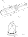
- FIG. 1 is a perspective view of an example of an ultrasonic intraoral wireless handheld device 100, also denoted ultrasonic handpiece, handheld probe, ultrasonic probe, or probe, according to some embodiments of the invention.
- the ultrasonic intraoral wireless handheld device comprises a probe body 105 and a probe head 110 also called a transducer assembly.
- probe body 105 comprises a housing 115 that may house a battery and electronic components (not represented), for example, a processing device configured to carry out steps as described by reference to Figures 4 to 8 .
- probe body 105 comprises an interface making it possible for a user to get information from the probe and to provide instructions to the probe.
- probe body 105 may comprise one or several buttons 120, a display 125, color LEDs (Light Emitting Devices) 130 (that are visible or located under the housing and visible through it when emitting light), a buzzer, an inertial measurement unit (not represented), and/or a haptic feedback vibrator (not represented).
- the inertial measurement unit makes it possible to detect user's actions like taps or double-taps, that may be used to interact with the ultrasonic probe. Using button 120 and short, long, and/or repeated clicks and/or using the inertial measurement unit, the user may browse through menus to get information from the probe and/or provide instructions to the probe.
- Probe body 105 also comprises mounting assembly 135 (located under a cover, which may be held in place by an elastic strap, and thus not visible) that makes it possible to mount a probe head to the probe body 105.
- probe head 110 comprises a support arm 140 having mounting assembly 145 at one end (cooperating with mounting assembly 135 and thus, located under the same cover), so that probe head 110 may be mounted on a probe body, and a transducer chamber 150 at the other end (also denoted acoustic chamber or transducer housing).
- Transducer chamber 150 houses one or several transducers that may be stationary or that may move in the acoustic chamber, for example that may oscillate, to emit ultrasound waves toward an object and measure the echo.
- the transducer is wirelessly connected to electronic components of the probe body or is connected to these electronic components through wires, for example and not limitation, coaxial wires.
- the transducer is mounted at one end of a shaft (not represented) that extends longitudinally through the support arm.
- a cam may be mounted on the other end of the shaft so as to control the movement of the transducer using a motor located in the probe body.
- the shaft may be hollow to allow the passage of a coaxial wire connecting the transducer to electronic components of the probe body.
- the acoustic chamber may house one or several transducers. These transducers may be of different nature.
- the one or several transducers may be stationary or moveable, the transducers may be a linear 1D or 2D array of transducers or an annular array of transducers, or the transducers may use the same transducers for emitting ultrasound signals and for receiving ultrasound signals or may use different transducers for emitting ultrasound signals and for receiving ultrasound signals, etc.
- the one or several transducers are generically referred to as a transducer in the following description.
- probe head 110 is a closed probe head having a transducer that is immersed in a sealed acoustic chamber filled with an internal acoustic coupling material such as a liquid or gel.
- the acoustic chamber may comprise solid coupling material that may be used, for example, to control the acoustic gradient of the acoustic chamber.
- Ultrasonic probe 100 may be used for clinical applications such as periodontology, implantology, restorative works, and buccal dermatology.
- ultrasonic probe 100 makes it possible to receive signals from which images of the soft tissues of a buccal space may be obtained, these images and/or signals enabling performing one or several of the following tasks:
- these tasks may be carried out lively during the acquisition process (i.e., real time), or during a post exam operation, once the data set of images and/or raw signal are acquired.
- imaging a portion of the inner surface of the transducer housing (or acoustic chamber), comprising one or more acoustic windows, and identifying the acoustic windows within the generated images are used to determine a precise reference position of the transducer with regard to the acoustic windows and to define an acquisition window within the acoustic window, wherein reliable measurements may be done. It is observed that an acoustic window is a portion of the transducer housing designed to let ultrasound signals through (i.e., reflection of ultrasound signals on the acoustic window is reduced as much as possible).
- the acoustic windows may be detectable, their thickness may be different from the thickness of the other portions of the housing, for instance, a fifth of the enclosure thickness.
- the acoustic impedance of the acoustic windows may differ from the acoustic impedance of the other parts of the enclosure ( e.g., different materials).
- the acoustic windows may be detectable according to specific curvature of the acoustic windows or of their frame. A detectable frame surrounding the acoustic windows or a particular coating may also be used.
- the material used to form the acoustic chamber may embed predetermined elements, acoustically detectable, that may be used as position references and/or as references to measure the intensity of echoed ultrasound signals.
- acoustically detectable elements behave like phantoms used to calibrate ultrasound probes.
- acoustic windows By carrying out measurements of ultrasound signal echoed on the inner surface of the acoustic chamber, on the outer surface of the acoustic chamber (preferably by holding the probe away from any reflective surface), and/or acoustically detectable elements of the acoustic chamber, it is possible to identify acoustic windows, to determine the distance (or time delay) between an acoustic window and the active surface of the transducer, to determine the acoustic transmission quality of the material between an acoustic window and the active surface of the transducer, etc., which can be used to determine some characteristics of the ultrasonic probe.
- such characteristics may be used for calibrating the ultrasonic probe (e.g., defining acquisition windows, identifying the position of the transducer that corresponds to the borders of the acquisition windows, etc.), for identifying any degradation of its performances, for adjusting some parameters of the ultrasonic probe, dynamically or not, for example for adjusting the gain of the acoustic probe so as to compensate acoustic attenuation of a worn gel or for calibrating a set of ultrasonic probes so that they share the same characteristics, etc.
- Figure 2 illustrates schematically a cross-section view of an acoustic chamber containing an oscillating transducer, the cross-section being perpendicular to the axis of rotation of the transducer (which may be parallel to the longitudinal axes of the ultrasonic probe).
- the acoustic chamber comprises one acoustic window 205 that acoustic characteristics are different from those of the other parts of the housing, for example its thickness is smaller than the one of the other part of the housing.
- the transducer may oscillate around axis 210 so as to emit ultrasound signals and receive corresponding echoed ultrasound signal within angular sector 215, delimited by angles A and B (for example from -38° to 38° with regard to axis 220 that is perpendicular to the acoustic window, in its center).
- Such an oscillating movement may result from a rotational mechanical crank comprising an eccentric or crank pin cooperating with a cam groove of a cam rigidly fastened to the transducer, as illustrated in Figure 3b .
- sector 215 is swept twice, as illustrated in Figure 3a , and the echoed ultrasound signals are measured in one direction only.
- sector 215 is swept twice and the echoed ultrasound signals are measured in both directions, as illustrated in Figures 5, 6, and 7 .
- sector 215 is swept twice and the echoed ultrasound signals are measured in both directions, the measures obtained in one direction being used for calibration or setting purposes and the measures obtained in the other direction being used for imaging soft tissue of a patient.
- calibration aims at identifying a reference position of the transducer and/or at estimating the position of acquisition windows.
- an acquisition window 225 (represented with the curve in bold), delimited by angular positions A' and B', may be determined in sector 215 wherein measurement can be done, the acquisition window representing a trade-off between measurement coverage and measurement quality.
- the transducer is moveable in translation or is stationary, the transducer being configured to emit and received ultrasound signals through the surface of the acoustic window, preferably the whole surface of the acoustic window.
- Figure 3 illustrates an example of a movement of a transducer for estimating characteristics of an ultrasonic probe.
- the transducer moves from angular position A to angular position B (phase 300) while carrying out high resolution measurements, next it moves faster from angular position B to angular position A (phase 305) while carrying out low resolution measurements or no measurement, next it moves again slower from angular position A to angular position B (phase 310) while carrying out high resolution measurements, and finally it moves faster from angular position B to angular position A (phase 315) while carrying out low resolution measurements or no measurement. It is noted that while no measurements are carried out during phases 305 and 315 when the ultrasonic probe is used to examine a patient, measurements are preferably carried out during these phases during an auto-diagnostic method.
- high resolution measurements may be done during phase 300 and 310 to examine a patient and low resolution measurements may be done during phase 305 and 315 for calibration or setting purposes. In such a case, the measurements done during phases 305 and/or 315 are not visible to the user. In addition, the measurements done during phase 305 and/or 315 may be used to improve the accuracy of the measurements done during phase 300 and/or 310 by adjusting dynamically some parameters of the probe.
- Figure 3b illustrates the angular position of the transducer with regard to the angular position of the motor's output shaft. Rotation of the motor's output shaft makes the transducer oscillate.
- the angular position of the transducer is represented on the ordinate axis (y-axis) while the angular position of the motor is provided on the abscissa axis (x-axis).
- An aspect of the auto-diagnostic method is to identify angular positions of the transducer with regard to the acquisition window (e.g., identifying the transducer angular positions corresponding to angular positions A' and/or B'), this position being expressed as a function of the corresponding position of the motor's output shaft that may be easily indexed (for example using a stepper motor, i.e., a motor that position may be commanded to move and hold one of several steps without any position sensor for feedback).
- a stepper motor i.e., a motor that position may be commanded to move and hold one of several steps without any position sensor for feedback.
- Figure 4 illustrates an example of steps of an auto-diagnostic method, for estimating characteristics of an ultrasonic probe.
- a first step of the method is directed to starting movement of the transducer (step 400), for example starting a motor making the transducer oscillate between two angular positions such as angular positions A and B in Figures 2 and 3 .
- an ultrasound (US) signal is emitted (step 405) and the echoed ultrasound signal is received and sampled (step 410).
- Raw data representing the time for the emitted signal to be echoed and received are computed and may be filtered (step 415).
- filtering the raw data may include ignoring raw data associated with ultrasound signals having time between emission and reception that is below a first threshold and/or above a second threshold, according to a temporal window of interest, that is to say raw data representing echoing surfaces that are too close and/or too far from the active surface of the transducer.
- the second threshold may be set in such a way as representing a distance of 1 cm between the active surface of the transducer and the echoing surface.
- the position of the transducer or of the motor's output shaft making the transducer oscillate, when emitting and receiving the ultrasound signal is obtained (step 420).
- This position and the raw data (possibly filtered) are stored (step 425).
- a test is carried out to determine whether the angular sector to be swept has been swept as requested (step 425), e.g., swept twice in a given direction. Steps 405 to 425 are repeated until all the measurements have been made.
- an image is generated from the stored raw data (step 435), for example, using a known method.
- An example of a generated image is illustrated in Figure 5 .
- the generated image and/or the raw data are then analyzed (step 440) to determine some characteristics of the ultrasonic probe such as acoustic windows, abnormalities within the acoustic path between the transducer and its housing, etc.
- Analyzing a generated image for detecting and localizing an acquisition window is described by reference to Figure 5 .
- Analyzing a generated image for detecting the presence of abnormalities such as air bubbles in an acoustic path is described by reference to Figure 6
- analyzing a generated image for refining the setting of an ultrasonic probe is described by reference to Figure 7 .
- Analyzing ultrasound signals for monitoring acoustic properties is described by reference to Figure 8 .
- a calibration parameter of the ultrasonic probe may be set or updated (step 445). For example, the relative position of the acquisition windows with regard to the transducer or with regard to the motor's output shaft making the transducer oscillate may be set or updated.
- some indications may be provided to the user or practitioner, for example to forewarn the user or practitioner about the need for changing ultrasonic probe parts such as the probe head if it appears that the liquid or gel fulfilling the acoustic chamber is no longer efficient.
- the steps illustrated in Figure 4 may be carried out upon request, for example upon a user's request, upon a request of a remote device (e.g., upon a request received from the provider/manufacturer (or other appropriate party) of the ultrasonic probe), or automatically, for example when starting or booting the ultrasonic probe.
- a remote device e.g., upon a request received from the provider/manufacturer (or other appropriate party) of the ultrasonic probe
- automatically for example when starting or booting the ultrasonic probe.
- the ultrasonic probe comprises a position sensor so that the steps illustrated in Figure 4 can be carried out only in particular positions of the probe, for example head up so (so that, for example, if air bubbles are present in the probe head, they can be detected), each time the ultrasonic probe is detected to be in a particular position, or on a periodic basis when detecting that the ultrasonic probe is in a particular position.
- Figure 5 illustrates an example of an image of a portion of the inner surface of a transducer housing, generated during an auto-diagnostic method, used for determining the position of an acquisition window.
- the ordinate axis represents the time delay between emission of an ultrasound signal and reception of the corresponding echoed ultrasound signal, which corresponds to the distance between the transducer and an echoing surface, that is to say the distance between the active surface of the transducer and the echoing surface.
- the abscissa axis represents the time at which the echoed ultrasound signal of which the time delay with the corresponding emitted ultrasound signal is represented on the abscissa axis, which represents a position of the transducer (or of the motor's output shaft that makes the transducer oscillate).
- the image, referenced 500 is representative of the shape (represented four times because of the two sweeps of the transducer) of a portion of the inner surface of the transducer housing.
- the part 505 of image 500 represents the measurements that have been carried out between angular position A and angular position B while the part 510 represents the measurements that have been carried out between angular position B and angular position A.
- the transducer is moving slower from angular portion A to angular position B than from angular portion B to angular position A (to improve angular resolution between angular portion A to angular position B).
- the cover/housing design it is possible to take advantage of the cover/housing design to create strong acoustic signal deviations, in order to delimitate the acoustic window borders. Indeed, to be reflected, the acoustic ultrasound waves need to hit planar or slightly tilted surfaces. Therefore, as soon as the tilt of a surface becomes too high, the ultrasound signals are not echoed towards the transducer. Thus, it is possible to adapt the design of the acoustic windows to the transducer assembly so that the acoustic windows may be easily detected.
- the acoustic window radius of curvature may be centered on the transducer rotation axis.
- the acoustic windows may follow the transducer array geometry (e.g., planar for a planar transducer array).
- the acoustic window radius of curvature may be centered on the transducer rotation axis to obtain 3D acoustic volumes.
- the strong acoustic signal deviations referenced 515, 520, 525, and 530 make it possible to identify acoustic windows. Combined with the shape of the represented signals (e.g., flat portions) and the width of some particular shapes (e.g., width of the flat portions) between these strong acoustic signal deviations, the acquisition window 535, located between strong acoustic signal deviations 515 and 520, corresponding to a large and substantially flat portion, may be determined. By identifying the portion 535 in image 500, borders A' and B' of the acquisition window and their abscissa may be determined.
- the position of the transducer (or of the motor making the transducer oscillate) stored at step 420 in Figure 4 and the abscissa corresponding to borders A' and B' the position of the transducer (or of the motor) at which it should start measuring and its position at which it should end measuring may be determined.
- start and end measuring angular positions may be stored as calibration data to be used as an acquisition window when examining a patient.
- acoustic window borders may be delimited by a strong tilt or angulation in the head covers (to use the acoustic beam deviation or reflection properties)
- other solutions exist such adding landmarks (e.g., grooves), phantoms, or markers or by modifying the acoustic properties of the acquisition windows with regard to the other portions of the transducer housing, for example using specific textures, material, or coating.
- the acquisition window makes it possible to determine which transducers of the array are to be active.
- Figure 6 illustrates an example of an image of a portion of the inner surface of the transducer housing, generated during an auto-diagnostic method, used for determining abnormalities in an acoustic path.
- Image 600 is similar to image 500. It is representative of the shape of a portion of the inner surface of the transducer housing and corresponds to two sweeps (forward and backward). It is used to detect the presence of defects such as air bubbles, surface damages, wearing or degradation of the internal couplant, suspended particles, etc., in the acoustic chamber.
- an air bubble is located in the middle of the acquisition window, as illustrated with references 605, 610, 615, and 620.
- identifying such an air bubble may be based on pattern recognition and/or by comparing the actual pattern with the expected pattern.
- an air bubble may be identified by identifying a hole in the image (i.e., because the air of the bubble does not reflect acoustic waves).
- the size of the air bubble may be determined by measuring the size of the hole. Such a size may be compared with one or more thresholds to determine whether the air bubble may be ignored, may be considered as acceptable, or should be considered as a significant issue.
- Figure 7 illustrates an example of an image of a portion of the inner surface of the transducer housing, generated during an auto-diagnostic method, used for refining the setting of an ultrasonic probe.
- Image 700 is similar to or the same as image 500. It is representative of the shape of a portion of the inner surface of the transducer housing and corresponds to two sweeps (forward and backward). It is used to carry out some measurements, for example determining the distance or time delay between the active surface of the transducer and the inner surface of the transducer housing, as illustrated with references 705, and/or the outer surface of the transducer housing.
- Determining such distances that may vary from one ultrasonic probe to another due to manufacturing reasons or inaccuracies, makes it possible to determine the time delay that should be set between exciting the transducer and sampling the echoed signal to avoid imaging the transducer housing and to harmonize transducer manufacturing (e.g., to set the same field of view in the soft tissues to all the probes of a set of probes).
- Figure 8 illustrates an example of an echoed ultrasound signal, measured during an auto-diagnostic method, used for monitoring acoustic properties of an acoustic chamber of an ultrasonic probe.
- the intensity of the ultrasound signal that is reflected by the inner surface of the transducer housing is measured and stored, at the time of manufacturing the ultrasonic probe (or at another time). It may be stored in a memory of the ultrasonic probe itself and/or in a memory or other data storage device of a nearby local computer/device or of a remote server.
- the intensity of the signal that is reflected by the inner surface of the transducer housing is measured and compared to the intensity of the echoed signal stored at the time of manufacturing the probe (or at the other time).
- Figure 8 represents a graph of the intensity (y-axis) of an echoed ultrasound signal over the time (x-axis).
- an echoed ultrasound signal may have a first peak of intensity 805 corresponding to a first surface of reflection (e.g., the inner surface of the acoustic chamber) and a second peak of intensity 810 corresponding to a second surface of reflection (e.g., the outer surface of the acoustic chamber).
- the intensity of the signal that is reflected by the inner surface of the transducer housing at the time of testing the ultrasonic probe and the intensity of the signal that is reflected by the inner surface of the transducer housing at the time of manufacturing the probe (or at the other time) is compared to a threshold.
- Degradation of the probe head is detected if the difference, in absolute value, between the intensity of the signal that is reflected by the inner surface of the transducer housing at the time of testing the ultrasonic probe and the intensity of the signal that is reflected by the inner surface of the transducer housing at the time of manufacturing the probe (or at the other time) is greater than the threshold.
- Such degradation may be signaled to the user of the ultrasonic probe or to someone in charge of the maintenance of the ultrasonic probe, for example for requesting the change of the probe head.
- such degradation may result from the wear of the internal couplant (e.g., the liquid or gel used to fill the acoustic chamber) contributing to the ultrasonic signal absorption and/or from a reduction of the transducer performance (a decrease of the intensity of the emitted ultrasonic signal induces a decrease of the intensity of the reflected signal sampled by the transducer).
- the internal couplant e.g., the liquid or gel used to fill the acoustic chamber
- Figure 9 is a schematic block diagram of a processing device for implementation of one or more embodiments of the invention, in particular for characterising an ultrasonic probe, as described by reference to Figures 4 to 8 .
- Processing device 900 comprises a communication bus connected to:
- the communication bus of computing device 900 may be connected to a hardware accelerator (e.g., an Artificial Intelligence accelerator module) and/or to a hard disk 925 denoted HD used as a mass storage device.
- a hardware accelerator e.g., an Artificial Intelligence accelerator module
- HD hard disk 925 denoted HD used as a mass storage device.
- the executable code may be stored either in read-only memory 915, on hard disk 925 or on a removable digital medium such as for example a disk.
- the executable code of the programs can be received by means of a communication network, via the network interface 920, in order to be stored in one of the storage means of the computing device 200, such as hard disk 925, before being executed.
- Central processing unit 905 is adapted to control and direct the execution of the instructions or portions of software code of the program or programs according to embodiments of the invention, the instructions being stored in one of the aforementioned storage means. After powering on, CPU 905 is capable of executing instructions from main RAM memory 910 relating to a software application after those instructions have been loaded from ROM 915 or from hard-disk 925 for example. Such a software application, when executed by CPU 905, causes the steps of the algorithms herein disclosed to be performed.
- Any step of the algorithm herein disclosed may be implemented in software by execution of a set of instructions or program by a programmable computing machine, such as a PC ("Personal Computer"), a laptop computer, a tablet computer, a smartphone or similar device, a DSP ("Digital Signal Processor") or a microcontroller; or else implemented in hardware by a machine or a dedicated component, such as an FPGA ("Field-Programmable Gate Array”) or an ASIC ("Application-Specific Integrated Circuit”).
- a programmable computing machine such as a PC ("Personal Computer"), a laptop computer, a tablet computer, a smartphone or similar device, a DSP ("Digital Signal Processor") or a microcontroller; or else implemented in hardware by a machine or a dedicated component, such as an FPGA (“Field-Programmable Gate Array") or an ASIC ("Application-Specific Integrated Circuit").
Landscapes
- Health & Medical Sciences (AREA)
- Life Sciences & Earth Sciences (AREA)
- Engineering & Computer Science (AREA)
- Physics & Mathematics (AREA)
- Heart & Thoracic Surgery (AREA)
- Surgery (AREA)
- Pathology (AREA)
- Radiology & Medical Imaging (AREA)
- Biophysics (AREA)
- Biomedical Technology (AREA)
- Veterinary Medicine (AREA)
- Medical Informatics (AREA)
- Molecular Biology (AREA)
- Nuclear Medicine, Radiotherapy & Molecular Imaging (AREA)
- Animal Behavior & Ethology (AREA)
- General Health & Medical Sciences (AREA)
- Public Health (AREA)
- Acoustics & Sound (AREA)
- Computer Networks & Wireless Communication (AREA)
- Physiology (AREA)
- Computer Vision & Pattern Recognition (AREA)
- Ultra Sonic Daignosis Equipment (AREA)
Priority Applications (2)
| Application Number | Priority Date | Filing Date | Title |
|---|---|---|---|
| EP23306213.2A EP4491129A1 (de) | 2023-07-13 | 2023-07-13 | Vorrichtungen und verfahren zur charakterisierung einer zahnärztlichen ultraschallsonde |
| PCT/US2024/037283 WO2025014984A1 (en) | 2023-07-13 | 2024-07-10 | Apparatuses and methods for characterizing a dental ultrasonic probe |
Applications Claiming Priority (1)
| Application Number | Priority Date | Filing Date | Title |
|---|---|---|---|
| EP23306213.2A EP4491129A1 (de) | 2023-07-13 | 2023-07-13 | Vorrichtungen und verfahren zur charakterisierung einer zahnärztlichen ultraschallsonde |
Publications (1)
| Publication Number | Publication Date |
|---|---|
| EP4491129A1 true EP4491129A1 (de) | 2025-01-15 |
Family
ID=87553816
Family Applications (1)
| Application Number | Title | Priority Date | Filing Date |
|---|---|---|---|
| EP23306213.2A Pending EP4491129A1 (de) | 2023-07-13 | 2023-07-13 | Vorrichtungen und verfahren zur charakterisierung einer zahnärztlichen ultraschallsonde |
Country Status (2)
| Country | Link |
|---|---|
| EP (1) | EP4491129A1 (de) |
| WO (1) | WO2025014984A1 (de) |
Citations (4)
| Publication number | Priority date | Publication date | Assignee | Title |
|---|---|---|---|---|
| US20130194891A1 (en) * | 2012-01-31 | 2013-08-01 | General Electric Company | Method and system for monitoring a transducer array in an ultrasound system |
| US20160131746A1 (en) * | 2014-11-07 | 2016-05-12 | General Electric Company | System and method for testing operability of a lens and selected transducer elements of an acoustic probe |
| US20180153517A1 (en) * | 2015-05-20 | 2018-06-07 | Sogang University Research Foundation | Apparatus and method for evaluating performance of ultrasonic transducer |
| WO2020148406A1 (en) | 2019-01-16 | 2020-07-23 | Trophy | Method of detecting an abnormality along a portion of a dental arch |
-
2023
- 2023-07-13 EP EP23306213.2A patent/EP4491129A1/de active Pending
-
2024
- 2024-07-10 WO PCT/US2024/037283 patent/WO2025014984A1/en active Pending
Patent Citations (4)
| Publication number | Priority date | Publication date | Assignee | Title |
|---|---|---|---|---|
| US20130194891A1 (en) * | 2012-01-31 | 2013-08-01 | General Electric Company | Method and system for monitoring a transducer array in an ultrasound system |
| US20160131746A1 (en) * | 2014-11-07 | 2016-05-12 | General Electric Company | System and method for testing operability of a lens and selected transducer elements of an acoustic probe |
| US20180153517A1 (en) * | 2015-05-20 | 2018-06-07 | Sogang University Research Foundation | Apparatus and method for evaluating performance of ultrasonic transducer |
| WO2020148406A1 (en) | 2019-01-16 | 2020-07-23 | Trophy | Method of detecting an abnormality along a portion of a dental arch |
Also Published As
| Publication number | Publication date |
|---|---|
| WO2025014984A1 (en) | 2025-01-16 |
Similar Documents
| Publication | Publication Date | Title |
|---|---|---|
| US20250090137A1 (en) | Ultrasonic periodontal probe | |
| JP6598667B2 (ja) | 被検体情報取得装置およびその制御方法 | |
| CN104739452A (zh) | 一种超声成像装置及方法 | |
| KR100763453B1 (ko) | 방광 진단용 초음파 진단 장치 및 초음파 진단 방법 | |
| EP4491129A1 (de) | Vorrichtungen und verfahren zur charakterisierung einer zahnärztlichen ultraschallsonde | |
| CN112826521A (zh) | 断层图像成像系统和方法 | |
| JP6376938B2 (ja) | 被検体情報取得装置 | |
| JP2010504834A (ja) | 不均一な回転歪みに影響された医用画像を修復するためのシステム及び方法 | |
| CN113349820A (zh) | 一种旋转扫描机械装置、三维超声成像系统及方法 | |
| JP6351357B2 (ja) | 音響波受信装置 | |
| EP4491122A1 (de) | Vielseitige dentale ultraschallsonde | |
| CN215605802U (zh) | 断层图像成像系统 | |
| CN209059264U (zh) | 一种高精度超声骨密度检测仪 | |
| EP4491130A1 (de) | Ultraschallsonde mit schnellkupplungskopf | |
| CN101978552B (zh) | 波导及具有波导的计算机断层摄影系统 | |
| KR100584096B1 (ko) | 다수 개의 트랜스듀서를 가진 초음파 측정장치 | |
| KR100681855B1 (ko) | 향상된 해상도의 이미지를 얻을 수 있는 초음파 측정방법 | |
| JP2025524150A (ja) | 超音波画像から歯周測定を実行するための方法、システム、およびコンピュータプログラム | |
| KR20030022458A (ko) | 중재적 초음파 분야에서 사용되는 침상 도구 | |
| JPH0249103B2 (de) | ||
| JP2018130442A (ja) | 計測装置および計測方法 |
Legal Events
| Date | Code | Title | Description |
|---|---|---|---|
| PUAI | Public reference made under article 153(3) epc to a published international application that has entered the european phase |
Free format text: ORIGINAL CODE: 0009012 |
|
| STAA | Information on the status of an ep patent application or granted ep patent |
Free format text: STATUS: THE APPLICATION HAS BEEN PUBLISHED |
|
| AK | Designated contracting states |
Kind code of ref document: A1 Designated state(s): AL AT BE BG CH CY CZ DE DK EE ES FI FR GB GR HR HU IE IS IT LI LT LU LV MC ME MK MT NL NO PL PT RO RS SE SI SK SM TR |
|
| STAA | Information on the status of an ep patent application or granted ep patent |
Free format text: STATUS: REQUEST FOR EXAMINATION WAS MADE |
|
| 17P | Request for examination filed |
Effective date: 20250710 |