EP4489331A1 - Personendetektionssystem, äusserungssystem und personendetektionsverfahren - Google Patents
Personendetektionssystem, äusserungssystem und personendetektionsverfahren Download PDFInfo
- Publication number
- EP4489331A1 EP4489331A1 EP23759736.4A EP23759736A EP4489331A1 EP 4489331 A1 EP4489331 A1 EP 4489331A1 EP 23759736 A EP23759736 A EP 23759736A EP 4489331 A1 EP4489331 A1 EP 4489331A1
- Authority
- EP
- European Patent Office
- Prior art keywords
- person
- transmitters
- antenna
- vicinity
- utterance
- Prior art date
- Legal status (The legal status is an assumption and is not a legal conclusion. Google has not performed a legal analysis and makes no representation as to the accuracy of the status listed.)
- Pending
Links
Images


Classifications
-
- G—PHYSICS
- G01—MEASURING; TESTING
- G01S—RADIO DIRECTION-FINDING; RADIO NAVIGATION; DETERMINING DISTANCE OR VELOCITY BY USE OF RADIO WAVES; LOCATING OR PRESENCE-DETECTING BY USE OF THE REFLECTION OR RERADIATION OF RADIO WAVES; ANALOGOUS ARRANGEMENTS USING OTHER WAVES
- G01S11/00—Systems for determining distance or velocity not using reflection or reradiation
- G01S11/02—Systems for determining distance or velocity not using reflection or reradiation using radio waves
- G01S11/06—Systems for determining distance or velocity not using reflection or reradiation using radio waves using intensity measurements
-
- G—PHYSICS
- G01—MEASURING; TESTING
- G01S—RADIO DIRECTION-FINDING; RADIO NAVIGATION; DETERMINING DISTANCE OR VELOCITY BY USE OF RADIO WAVES; LOCATING OR PRESENCE-DETECTING BY USE OF THE REFLECTION OR RERADIATION OF RADIO WAVES; ANALOGOUS ARRANGEMENTS USING OTHER WAVES
- G01S13/00—Systems using the reflection or reradiation of radio waves, e.g. radar systems; Analogous systems using reflection or reradiation of waves whose nature or wavelength is irrelevant or unspecified
- G01S13/02—Systems using reflection of radio waves, e.g. primary radar systems; Analogous systems
- G01S13/04—Systems determining presence of a target
-
- G—PHYSICS
- G01—MEASURING; TESTING
- G01S—RADIO DIRECTION-FINDING; RADIO NAVIGATION; DETERMINING DISTANCE OR VELOCITY BY USE OF RADIO WAVES; LOCATING OR PRESENCE-DETECTING BY USE OF THE REFLECTION OR RERADIATION OF RADIO WAVES; ANALOGOUS ARRANGEMENTS USING OTHER WAVES
- G01S13/00—Systems using the reflection or reradiation of radio waves, e.g. radar systems; Analogous systems using reflection or reradiation of waves whose nature or wavelength is irrelevant or unspecified
- G01S13/02—Systems using reflection of radio waves, e.g. primary radar systems; Analogous systems
- G01S13/50—Systems of measurement based on relative movement of target
- G01S13/52—Discriminating between fixed and moving objects or between objects moving at different speeds
- G01S13/56—Discriminating between fixed and moving objects or between objects moving at different speeds for presence detection
-
- G—PHYSICS
- G06—COMPUTING OR CALCULATING; COUNTING
- G06F—ELECTRIC DIGITAL DATA PROCESSING
- G06F3/00—Input arrangements for transferring data to be processed into a form capable of being handled by the computer; Output arrangements for transferring data from processing unit to output unit, e.g. interface arrangements
- G06F3/01—Input arrangements or combined input and output arrangements for interaction between user and computer
-
- G—PHYSICS
- G06—COMPUTING OR CALCULATING; COUNTING
- G06F—ELECTRIC DIGITAL DATA PROCESSING
- G06F3/00—Input arrangements for transferring data to be processed into a form capable of being handled by the computer; Output arrangements for transferring data from processing unit to output unit, e.g. interface arrangements
- G06F3/16—Sound input; Sound output
-
- G—PHYSICS
- G10—MUSICAL INSTRUMENTS; ACOUSTICS
- G10L—SPEECH ANALYSIS TECHNIQUES OR SPEECH SYNTHESIS; SPEECH RECOGNITION; SPEECH OR VOICE PROCESSING TECHNIQUES; SPEECH OR AUDIO CODING OR DECODING
- G10L13/00—Speech synthesis; Text to speech systems
- G10L13/02—Methods for producing synthetic speech; Speech synthesisers
-
- H—ELECTRICITY
- H04—ELECTRIC COMMUNICATION TECHNIQUE
- H04B—TRANSMISSION
- H04B17/00—Monitoring; Testing
- H04B17/30—Monitoring; Testing of propagation channels
- H04B17/309—Measuring or estimating channel quality parameters
- H04B17/318—Received signal strength
Definitions
- the present disclosure relates to a person detection system, an utterance system, and a person detection method that detect whether a person is present.
- Patent Literature (PTL) 1 discloses a system for presence detection.
- data indicative of signal strength associated with radio frequency (RF) signals received by one or more devices communicating via a wireless communications protocol is monitored.
- presence of at least one person in the vicinity of the one or more devices is determined based on a comparison of the data monitored to a baseline signal strength profile.
- RF radio frequency
- the present disclosure provides a person detection system or the like that can detect whether a person is present without preparing an additional device.
- a person detection system includes an obtainer and a processing unit.
- the obtainer obtains a signal strength of a radio wave transmitted by each of a plurality of transmitters and received by an antenna.
- the processing unit performs a detection process of detecting whether a person is present in a vicinity of the antenna, based on the signal strengths obtained by the obtainer.
- Each of the plurality of transmitters is classified into any one of a plurality of groups according to a position of the transmitter with respect to the antenna.
- the processing unit detects that the person is present in the vicinity of the antenna when each of the signal strengths obtained by the obtainer regarding, among the plurality of transmitters, two or more transmitters classified into a same group among the plurality of groups deviates from a normal range.
- a person detection system includes an obtainer and a processing unit.
- the obtainer obtains a signal strength of a radio wave transmitted by each of a plurality of transmitters and received by an antenna.
- the processing unit performs a detection process of detecting whether a person is present in a vicinity of the antenna, based on the signal strengths obtained by the obtainer. In the detection process, the processing unit detects that the person is present in the vicinity of the antenna when each of the signal strengths obtained by the obtainer regarding, among the plurality of transmitters, two or more transmitters deviates from a normal range.
- An utterance system includes the person detection system, the antenna, a voice outputter that outputs voice, and a controller.
- the controller causes the voice outputter to output the voice when the person detection system detects that the person is present in the vicinity of the antenna.
- a person detection method obtains a signal strength of a radio wave transmitted by each of a plurality of transmitters and received by an antenna.
- the person detection method performs a detection process of detecting whether a person is present in a vicinity of the antenna, based on the signal strengths obtained.
- Each of the plurality of transmitters is classified into any one of a plurality of groups according to a position of the transmitter with respect to the antenna.
- the person detection method detects that the person is present in the vicinity of the antenna when each of the signal strengths obtained by the obtainer regarding, among the plurality of transmitters, two or more transmitters classified into a same group among the plurality of groups deviates from a normal range.
- a program according to an aspect of the present disclosure causes one or more processors to execute the person detection method.
- a person detection system or the like according to the present disclosure has the advantage that it is possible to detect whether a person is present without preparing an additional device.
- the above-described problem may be solved by causing the utterance device to notify the details of the event when the user is detected to be present in the vicinity of the utterance device.
- a sensor that detects a person is provided so that the vicinity of the utterance device is set as a detection range, for example.
- the cost increases because the sensor needs to be provided in addition to the utterance device.
- detection of whether the user is present in the vicinity of the utterance device is performed based on a signal strength of a radio wave transmitted from a mobile terminal, such as a smartphone, that is possessed by the user, for example. Since a signal strength of a radio wave that is received by the utterance device varies according to distance between the utterance device and the smartphone, it is possible to detect whether the user carrying the smartphone is present in the vicinity of the utterance device by causing the utterance device to measure a signal strength.
- a dedicated transmitter is provided in a space including the installation place of the utterance device, and detection of whether a user is present in the vicinity of the utterance device is performed by detecting attenuation of a radio wave caused by a human body when a user is present between the utterance device and the dedicated transmitter, for example.
- the dedicated transmitter needs to be provided in addition to the utterance device.
- a range in which detection of whether a user is present can be performed varies according to the installation place of the dedicated transmitter because detection of whether a user is present is performed between the dedicated transmitter and the utterance device.
- the present disclosure is conceived in view of the above.
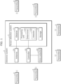
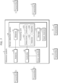
- FIG. 1 is a block diagram illustrating the overall configuration including person detection system 1 according to Embodiment 1.
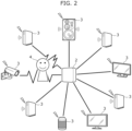
- FIG. 2 illustrates an environment in which utterance system 2 (person detection system 1) according to Embodiment 1 is provided.
- Person detection system 1 is a system for detecting whether person 4 is present in the vicinity of utterance system 2, more specifically, antenna 21 included in utterance system 2.
- person 4 is assumed to be a user who uses utterance system 2
- person 4 may be a person other than the user.
- person detection system 1 detects person 4 without identifying the attribute of person 4.
- person detection system 1 is used in an environment in which utterance system 2 (more specifically, antenna 21) is provided and a plurality of transmitters 3 present around utterance system 2.
- Transmitter 3 is a device that transmits a radio wave and provided inside or outside of a building in which the user lives.
- transmitter 3 may be a device, such as an information source device to be described later, possessed by the user or a device possessed by another person.
- transmitter 3 is a device that performs a wireless communication in accordance with a wireless communication standard such as Wi-Fi (registered trademark) or Bluetooth (registered trademark) Low Energy (BLE). It is sufficient that transmitter 3 be a device that transmits a radio wave that can be received by antenna 21 of utterance system 2, and the function of transmitter 3 is not particularly limited.
- the examples of transmitter 3 may include an Internet of Things (IoT) device, a BLE device, and the like. More specifically, the examples of transmitter 3 may include a relay device such as a router, a beacon, a home appliance such as a television receiver or a smart speaker, a sensor, a surveillance camera, and the like.
- Utterance system 2 is a system capable of notifying the user of details of an event that has occurred in an information source device or an information source service. Utterance system 2 notifies the details of the event by outputting voice from voice outputter 23 such as a loudspeaker, for example. It should be noted that notification by utterance system 2 may be performed by displaying text, an image, or the like on a display provided in utterance system 2, in addition to the outputting of voice.
- the information source device is a device that is a source of information to be notified by notification device 2.
- the information source device is a home appliance.
- the information source device is, for example, an air conditioning device, a washing machine, a robotic vacuum cleaner, a refrigerator, a rice cooker, a microwave oven, or the like.
- the examples of event that occurs in the information source device may include start or completion of an operation of the information source device, occurrence of an error in the information source device, maintenance of the information source device, and the like.
- the information source service is a service that is a source of information to be notified by notification device 2 and, for example, is a service that is provided to the user from a server or the like operated by a service provider.
- the information source service is, for example, a transport service or a weather forecast service.
- the examples of an event that occurs in the information source service may include start or completion of a service by the information source service, occurrence of an error in the information source service, and the like.
- utterance system 2 is an utterance device having a voice output function as described above and is provided in a building in which the user lives, for example.
- utterance system 2 is implemented as a dedicated device. It should be noted that utterance system 2 may be implemented as a function of a home appliance such as a smart speaker, a television receiver, a lighting appliance, a pet camera, an interphone master unit, an interphone sub unit, or an air conditioning device, for example.
- Utterance system 2 includes person detection system 1, antenna 21, controller 22, and voice outputter 23.
- utterance system 2 includes a processor and a memory, and controller 22 included in utterance system 2 is implemented by the processor executing a computer program stored in the memory.
- Antenna 21 functions as part of a communication interface of utterance system 2.
- Antenna 21 receives a signal (radio wave) transmitted from the information source device or the information source service, via a network such as the Internet or a wireless local area network (LAN), for example.
- antenna 21 receives radio waves transmitted from the plurality of transmitters 3.
- transmitter 3 is the information source device
- antenna 21 receives a radio wave transmitted from the information source device to utterance system 2.
- antenna 21 receives a radio wave transmitted from transmitter 3.
- Utterance system 2 may include a single antenna 21 or a plurality of antennas 21.
- controller 22 When receiving a signal transmitted from the information source device or the information source service, controller 22 causes voice outputter 23 to output voice according to the content of the signal received. For example, controller 22 causes voice outputter 23 to output voice corresponding to voice data included in the signal received.
- controller 22 may retrieve, from the memory, corresponding voice data in accordance with an instruction included in the signal received and then cause voice outputter 23 to output voice corresponding to the voice data retrieved.
- controller 22 may generate corresponding voice data in accordance with an instruction included in the signal received and then cause voice outputter 23 to output voice corresponding to the voice data generated.
- controller 22 causes voice outputter 23 to output voice when person 4 is detected to be present in the vicinity of antenna 21 by person detection system 1. In other words, even when receiving a signal transmitted from the information source device or the information source service, controller 22 does not control voice outputter 23 and stands by until when person detection system 1 detects that person 4 is present. Then, when person detection system 1 detects that person 4 is present, controller 22 causes voice outputter 23 to output voice.
- utterance system 2 since utterance system 2 according to Embodiment 1 can output voice only when person 4 is present around antenna 21 (utterance system 2), there is the advantage that content (e.g., details of an event that has occurred in the information source device or the information source service) indicated by the voice can be easily notified to person 4.
- content e.g., details of an event that has occurred in the information source device or the information source service
- Voice outputter 23 outputs voice.
- voice outputter 23 is a loudspeaker.
- Voice outputter 23 is controlled, by controller 22, to convert voice data transmitted from controller 22 into voice and output the voice converted.
- person detection system 1 includes obtainer 11, processing unit 12, and storage 13. Although person detection system 1 includes storage 13 in Embodiment 1, storage 13 need not be a constituent element of person detection system 1.
- person detection system 1 is installed inside a device including utterance system 2, and is a part of constituent elements of utterance system 2. It should be noted that person detection system 1 may be implemented as a device that is separate from utterance system 2, that is, person detection system 1 need not be a constituent element of utterance system 2.
- Person detection system 1 includes a processor and a memory, and each of the constituent elements included in person detection system 1 is implemented by the processor executing a computer program stored in the memory.
- the memory is storage 13.
- Obtainer 11 obtains signal strengths of radio waves transmitted by the plurality of transmitters 3 and received by antenna 21.
- obtainer 11 measures a received signal strength indicator (RSSI) value of a radio wave received by antenna 21 and obtains the RSSI value measured as a signal strength value.
- RSSI received signal strength indicator
- obtainer 11 obtains an RSSI value from each of the plurality of transmitters 3.
- obtainer 11 obtains RSSI values by distinguishing the RSSI values according to respective transmission source addresses included in radio waves transmitted from the plurality of transmitters 3.
- the RSSI values obtained by obtainer 11 are stored in storage 13 on a transmitter 3 basis.
- obtainer 11 obtains, for each of the plurality of transmitters 3, a signal strength value at certain time intervals (e.g., at every several seconds).
- Processing unit 12 performs a detection process of detecting whether person 4 is present in the vicinity of antenna 21, based on the signal strengths obtained by obtainer 11.
- processing unit 12 detects that person 4 is present in the vicinity of antenna 21 when each of the signal strengths obtained by obtainer 11 regarding, among the plurality of transmitters 3, two or more transmitters 3 deviates from a corresponding one of normal ranges.
- a normal range is a range in which a signal strength is generally constant, more specifically, a range of a signal strength measured in an environment in which person 4 is not present around antenna 21 (utterance system 2).
- antenna 21 of utterance system 2 receives radio waves transmitted from the plurality of transmitters 3 present around utterance system 2.
- a signal strength of a radio wave transmitted from each of the plurality of transmitters 3 and received by antenna 21 is generally constant, that is, is in a corresponding one of the normal ranges since the radio waves transmitted from the plurality of transmitters 3 to antenna 21 are not attenuated by person 4.
- person 4 When person 4 is present around utterance system 2, person 4 is present between utterance system 2 and any one or more of the plurality of transmitters 3.
- person 4 when person 4 is present in the vicinity of one of the plurality of transmitters 3, person 4 is present only in the path of a radio wave transmitted from the one of the plurality of transmitters 3 and only the radio wave transmitted from the one of the plurality of transmitters 3 is disturbed by the presence of person 4.
- person 4 is present in the vicinity of utterance system 2
- person 4 when person 4 is present in the vicinity of utterance system 2, person 4 is present in the paths of radio waves transmitted from two transmitters 3 located in a generally same direction as viewed from utterance system 2, among the plurality of transmitters 3, as illustrated in FIG. 2 for example, and both of the radio waves transmitted from the two transmitters 3 are disturbed by the presence of person 4.
- person detection system 1 detects that person 4 is present in the vicinity of antenna 21. Person detection system 1 determines that a radio wave transmitted from transmitter 3 is disturbed due to the fact that a signal strength (RSSI value) of the radio wave deviates from a corresponding one of the normal ranges.
- RSSI value signal strength
- processing unit 12 includes determiner 121 that performs a determination process of determining the above-described normal ranges and detector 122 that performs the above-described detection process.
- the function of determiner 121 is implemented by the processor executing a computer program that corresponds to determiner 121 and is stored in the memory.
- the function of detector 122 is implemented by the processor executing a computer program that corresponds to detector 122 and is stored in the memory.
- Determiner 121 performs the determination process.
- processing unit 12 performs the determination process of determining, for each of the plurality of transmitters 3, a normal range based on the signal strength obtained by obtainer 11 regarding the transmitter 3.
- the normal ranges determined by determiner 121 are stored in storage 13 on a transmitter 3 basis.
- determiner 121 periodically performs the determination process as described later to thereby periodically update the normal ranges individually for each of the plurality of transmitters 3.
- determiner 121 may be triggered to perform the determination process when a predetermined operation is performed by the user of person detection system 1, to thereby irregularly update the normal ranges individually for each of the plurality of transmitters 3, for example.
- Detector 122 performs the detection process.
- detector 122 detects that person 4 is present in the vicinity of antenna 21 when each of the signal strengths obtained by obtainer 11 regarding, among the plurality of transmitters 3, two or more transmitters 3 is determined to deviate from a corresponding one of the normal ranges, by referring to the normal ranges determined by determiner 121.
- FIG. 3 is a flowchart illustrating an example of the determination process in person detection system 1 according to Embodiment 1.
- a description is given by focusing on a single transmitter 3 among a plurality of transmitters 3.
- a series of processes (S102 and S103) described below is performed for each of the plurality of transmitters 3.
- determiner 121 obtains the present time by using a build-in or external timer and stands by until the present time reaches a predetermined time period (S101: No).
- the predetermined time period is a time period in which it is assumed that person 4 is not present in a space where antenna 21, that is, utterance system 2 is present.
- the space where utterance system 2 is provided is a living room
- a late-night time period in which it is assumed that person 4 is sleeping is set as the predetermined time period.
- a time period from 1 a.m. to 5 a.m. is exemplified as the predetermined time period.
- determiner 121 divides the predetermined time period by a certain time period (e.g., 10 minutes) and aggregates signal strength values obtained by obtainer 11 in each of the certain time periods (S102). Then, determiner 121 determines a normal range of transmitter 3 based on the aggregation result of the signal strength values (S103). The normal range determined by determiner 121 is stored in storage 13.
- a certain time period e.g. 10 minutes
- S102 aggregates signal strength values obtained by obtainer 11 in each of the certain time periods
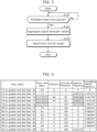
- FIG. 4 illustrates an example of the normal range.
- “class” indicates each of ranges into which the range of the aggregated signal strength values is divided by a certain value (here, 2 dBm), and “class mark” indicates an average value of the signal strength values in a particular class.
- “frequency” indicates the number of times a signal strength value belonging to a particular class is obtained. For example, the frequency of class "RSSI: -72 or greater and less than -70" is "1", and this means that, among the signal strength values obtained by obtainer 11 in the certain time period, the number of times a signal strength value in the range of class "RSSI: -72 or greater and less than -70" is obtained is 1.
- “cumulative frequency” indicates the sum of frequencies of the class having the highest signal strength value and the subsequent class(es) up to and including a particular class. Furthermore, in FIG. 4 , “relative frequency” indicates a value calculated by dividing frequency of a particular class by the total value of frequencies of all the classes, and “cumulative relative frequency” indicates the sum of relative frequencies of the class having the highest signal strength value and the subsequent class(es) up to and including a particular class
- an average value of the signal strength values (here, RSSI values) and convergence of the signal strength values are important for determining whether disturbance due to presence of person 4 has occurred in a radio wave transmitted from transmitter 3.
- RSSI values the signal strength values in the normal range are relatively high.
- a signal strength varies when person 4 is present in the vicinity of antenna 21, it is important that the signal strength values in the normal range are converged.
- determiner 121 sorts the classes in the aggregation result of the signal strength values in descending order of the relative frequency, and calculates the sum of the highest relative frequency, the second highest relative frequency, and the third highest relative frequency. Then, determiner 121 determines that the signal strength values of the radio wave transmitted from transmitter 3 are relatively converged, that is, a first condition is satisfied when the sum of the highest three relative frequencies is 0.9 or greater, that is, when the sum of the highest three frequencies constitutes 90% or more of the frequencies of all the classes.
- determiner 121 determines that the signal strength values of the radio wave transmitted from transmitter 3 are relatively high, that is, a second condition is satisfied when an average value of the class marks of these three classes having the highest three relative frequencies is a certain value (here, -80 dBm) or greater. Then, determiner 121 determines, as the normal range, the class marks of these three classes, the average value of the class marks of these three classes, and the sum of the relative frequencies of these three classes when the first condition and the second condition are satisfied.
- the class having the highest relative frequency is class "RSSI: -76 or greater and less than -74”
- the class having the second highest relative frequency is class “RSSI: -74 or greater and less than -72”
- the class having the third highest relative frequency is class “RSSI: -78 or greater and less than -76”.
- the sum of the relative frequencies of these three classes is "0.98" and the first condition is satisfied.
- an average value of the class marks of these three classes is "-75" and the second condition is satisfied. Accordingly, determiner 121 determines the class marks of these three classes, the average value of the class marks of these three classes, and the sum of the relative frequencies of these three classes, as the normal range.
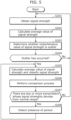
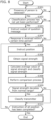
- FIG. 5 is a flowchart illustrating an operation example of person detection system 1 according to Embodiment 1. Hereinafter, description is carried out under the assumption that normal ranges for a plurality of transmitters 3 are stored in advance in storage 13, by the determination process performed by determiner 121.
- obtainer 11 obtains signal strength values of a radio wave transmitted from each of the plurality of transmitters 3 (S201). Then, detector 122 calculates, for each of the plurality of transmitters 3, an average value of the signal strength values obtained by obtainer 11 regarding the transmitter 3 (S202). Here, detector 122 calculates, for each of the plurality of transmitters 3, an average value of the signal strength values by performing an exponentially weighted moving average process on a past plurality (e.g., several tens) of data obtained by obtainer 11 regarding the transmitter 3.
- detector 122 determines, for each of the plurality of transmitters 3, whether an instantaneous value of a signal strength is an outlier by referring to the average value of the signal strength values calculated regarding the transmitter 3 (S203). In Embodiment 1, detector 122 determines that the instantaneous value of the signal strength is an outlier when the instantaneous value of the signal strength is attenuated to less than the average value and the deviation of the instantaneous value of the signal strength from the average value is several (e.g., three) times or more greater than the standard deviation.
- detector 122 When an outlier has not occurred regarding any of the plurality of transmitters 3 (S204: No), detector 122 does not perform the detection process and repeats steps S201 to S203. On the other hand, when an outlier has occurred regarding any of the plurality of transmitters 3 (S204: Yes), detector 122 performs the detection process and processes in step S205 and subsequent steps. In other words, processing unit 12 performs the detection process when an instantaneous value of a signal strength obtained by obtainer 11 regarding any one of the plurality of transmitters 3 is attenuated by a predetermined value or more.
- detector 122 calculates, for each of the plurality of transmitters 3, an average value of a predetermined number of (e.g., 10) signal strength values obtained by obtainer 11 regarding the transmitter 3 and classifies the predetermined number of signal strength values into classes (S205). Then, detector 122 performs, for each of the plurality of transmitters 3, a comparison process of comparing the average value of the signal strength values calculated and the signal strength values classified with a corresponding one of the normal ranges (S206).
- a predetermined number of e.g. 10
- detector 122 detects that a signal strength deviates from a corresponding one of the normal ranges when a first determination condition, a second determination condition, and a third determination condition are satisfied.
- the first determination condition requires that the average value of signal strength values calculated be less than the average value of signal strength values in a corresponding one of the normal ranges.
- the second determination condition requires that at least one of the class marks of three classes having the highest three relative frequencies in the signal strength values classified does not match with any of the class marks of three classes having the highest three relative frequencies in a corresponding one of the normal ranges.
- the third determination condition requires that the total of the highest three relative frequencies in the signal strength values classified be less than or equal to a certain value (e.g., 0.8).
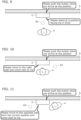
- FIG. 6 illustrates disturbance in signal strengths in a state where person 4 is present in the vicinity of antenna 21.
- FIG. 6 illustrates an example in which disturbance has occurred in each of radio waves transmitted from a first transmitter and a second transmitter among the plurality of transmitters 3, due to presence of person 4 in the vicinity of antenna 21 in the time period from time t1 to time t2.
- FIG. 6 illustrates time series data of the signal strength values (here, RSSI values) of each of the radio waves transmitted from the first transmitter and the second transmitter.
- the signal strength values are less than "Av1" which is the average value of signal strength values in a corresponding one of the normal ranges, and the distribution of the signal strength values is uneven compared with that in the normal range.
- an outlier has occurred as indicated by a circle, among the signal strength values.
- detector 122 is triggered to perform the detection process when the outlier has occurred regarding the first transmitter.
- utterance system 2 For detecting whether person 4 such as a user or the like is present in the vicinity of an utterance device (utterance system 2), it can be considered that a sensor that detects a person or a dedicated transmitter is provided in a space including the installation place of utterance system 2, for example.
- a sensor that detects a person or a dedicated transmitter is provided in a space including the installation place of utterance system 2, for example.
- the cost increases because another device needs to be prepared in addition to the utterance device.
- a mobile terminal such as a smartphone
- a mobile terminal possessed by person 4 since the mobile terminal possessed by person 4 is used, there is no need to prepare another device in addition to the utterance device.
- the mobile terminal possessed by person 4 since the mobile terminal possessed by person 4 is used, there is no need to prepare another device in addition to the utterance device.
- person detection system 1 (person detection method) according to Embodiment 1 uses signal strengths of radio waves transmitted from a plurality of preexisting transmitters 3 around antenna 21 (utterance system 2) to detect whether person 4 is present in the vicinity of antenna 21 (utterance system 2). Accordingly, in person detection system 1 (person detection method) according to Embodiment 1, there is no need to prepare another device in addition to utterance system 2, unlike the case in which a sensor that detects a person or a dedicated transmitter is used.
- person detection system 1 person detection method
- Embodiment 1 it is possible to easily detect whether person 4 is present in the vicinity of utterance system 2 since the position of a device which is a transmission source of a radio wave is fixed, unlike the case in which a mobile terminal is used. Accordingly, person detection system 1 (person detection method) according to the embodiment has the advantage that it is possible to detect whether person 4 is present without preparing an additional device.
- FIG. 7 is a block diagram illustrating the overall configuration including person detection system 1A according to Embodiment 2.
- Person detection system 1A is different from person detection system 1 according to Embodiment 1 in that person detection system 1A further includes input receiver 14.
- person detection system 1A is different from person detection system 1 according to Embodiment 1 in that processing unit 12 of person detection system 1A further includes instructor 123 and classifier 124.
- processing unit 12 of person detection system 1A further includes instructor 123 and classifier 124.
- Input receiver 14 is, for example, a push button or the like that is exposed to the outside of a housing accommodating utterance system 2, and receives an input by person 4.
- person 4 present around antenna 21 (utterance system 2) is instructed by voice, person 4 uses input receiver 14 to respond the instruction.
- Instructor 123 gives various instructions to person 4 present around antenna 21 (utterance system 2). Specifically, instructor 123 transmits, to controller 22 of utterance system 2, an instruction signal including content of an instruction to person 4. Accordingly, controller 22 causes voice outputter 23 to output, by voice, the content of the instruction included in the instruction signal.
- the function of instructor 123 is implemented by a processor executing a computer program that corresponds to instructor 123 and is stored in a memory.
- Classifier 124 (i.e., processing unit 12) performs a classification process of classifying each of a plurality of transmitters 3 into any one of a plurality of groups according to a position of the transmitter 3 with respect to antenna 21. Specifically, classifier 124 classifies, among the plurality of transmitters 3, two or more transmitters 3 located in a generally same direction as viewed from antenna 21 (utterance system 2) into the same group, by performing the classification process. Classification information related to the groups classified by classifier 124 is stored in storage 13. In Embodiment 2, classifier 124 performs the classification process when the classification process has not yet been performed, as described later. Classifier 124 may update the classification information by performing the classification process when the classification process has already been performed. The function of classifier 124 is implemented by the processor executing a computer program that corresponds to classifier 124 and is stored in the memory.
- a detection process by detector 122 is different from the detection process in person detection system 1 according to Embodiment 1.
- detector 122 i.e., processing unit 12
- detector 122 detects that person 4 is not present in the vicinity of antenna 21 when the two or more transmitters 3 belong to mutually different groups, that is, are located in mutually different directions as viewed from antenna 21.
- detector 122 detects that person 4 is present in the vicinity of antenna 21 when each of the signal strengths obtained by obtainer 11 regarding, among the plurality of transmitters 3, two or more transmitters 3 deviates from a corresponding one of the normal ranges, as with Embodiment 1.
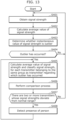
- FIG. 8 is a flowchart illustrating an example of the classification process in person detection system 1A according to Embodiment 2.
- instructor 123 transmits an instruction signal to controller 22 of utterance system 2 to thereby instruct output of a question message (S303). Accordingly, controller 22 causes voice outputter 23 to output the question message by voice.
- the question message is a message for inquiring of person 4 whether to perform the classification process.
- the question message includes a message for instructing person 4 to perform an operation on an utterance device (utterance system 2) when the classification process is allowed to be performed.
- instructor 123 does not do anything particular.
- Processing unit 12 waits for a response to the question message from person 4 for a certain time period (e.g., several tens of seconds) from when the question message is outputted by voice. Then, when processing unit 12 receives the response within the certain time period by receiving an input by person 4 by input receiver 14 (S304: Yes), classifier 124 performs the classification process and the processes in step S305 and the subsequent steps described later. On the other hand, when processing unit 12 does not receive the response within the certain time period (S304: No), classifier 124 does not do anything particular.
- a certain time period e.g., several tens of seconds
- processing unit 12 causes instructor 123 to instruct the standing position of person 4 (S305).
- Instructor 123 transmits an instruction signal to controller 22 of utterance system 2 to thereby instruct output of a position instruction message.
- controller 22 causes voice outputter 23 to output the position instruction message by voice.
- the position instruction message is a message for requiring person 4 to move to a predetermined standing position.
- the position instruction message includes a message for instructing person 4 to perform an operation on the utterance device (utterance system 2) when person 4 has arrived at the predetermined standing position.
- obtainer 11 obtains, for each of the plurality of transmitters 3, a predetermined number of (e.g., 10) signal strength values (S306).
- classifier 124 calculates, for each of the plurality of transmitters 3, an average value of the predetermined number of signal strength values obtained by obtainer 11 regarding the transmitter 3 and classifies the predetermined number of signal strength values into classes (S307).
- classifier 124 performs, for each of the plurality of transmitters 3, a comparison process of comparing the average value of the signal strength values calculated and the signal strength values classified with a corresponding one of the normal ranges (S308).
- the comparison process is the same as that in Embodiment 1 and the description thereof is omitted here.
- classifier 124 classifies the one or more transmitters 3 into a group corresponding to the predetermined standing position (S310).
- classifier 124 does not do anything particular.
- processing unit 12 repeats a series of processes in steps S305 to S310 while changing the standing position of person 4. Then, when processing unit 12 has instructed person 4 to move to all of the standing positions (S311: Yes), processing unit 12 completes the classification process.
- Classification information related to the groups classified by classifier 124 is stored in storage 13.
- instructor 123 may transmit an instruction signal to controller 22 of utterance system 2 to thereby instruct output of a completion message. Accordingly, controller 22 causes voice outputter 23 to output the completion message by voice.
- the completion message is a message for informing person 4 of completion of the classification process.
- FIG. 9 illustrates a first instruction to person 4 in the classification process.
- FIG. 10 illustrates a second instruction to person 4 in the classification process.
- FIG. 11 illustrates a third instruction to person 4 in the classification process.
- an utterance device (utterance system 2) is provided on wall 5.
- the first instruction person 4 is instructed to stand at first position A1 that is in front of the utterance device (utterance system 2).
- voice outputter 23 outputs by voice, as the position instruction message, the message "Please stand at a position facing me in front” for prompting a movement to first position A1 and the message "Please push the button when you arrive at the position” for prompting an operation when the movement has been completed.
- person 4 moves to first position A1 and performs an input operation on the utterance device (utterance system 2).
- the second instruction person 4 is instructed to stand at second position A2 that is on the right side as viewed from person 4, that is, on the front left side as viewed from the utterance device (utterance system 2).
- voice outputter 23 outputs by voice, as the position instruction message, the message "Please move to the right side and come next to me” for prompting a movement to second position A2 and the message "Please push the button when you arrive at the position” for prompting an operation when the movement has been completed.
- person 4 moves from first position A1 to second position A2 and performs an input operation on the utterance device (utterance system 2).
- the third instruction person 4 is instructed to stand at third position A3 that is on the left side as viewed from person 4, that is, on the front right side as viewed from the utterance device (utterance system 2).
- voice outputter 23 outputs by voice, as the position instruction message, the message "Please move to the opposite side from the current position and come next to me” for prompting a movement to third position A3 and the message "Please push the button when you arrive at the position” for prompting an operation when the movement has been completed.
- person 4 moves from second position A2 to third position A3 and performs an input operation on the utterance device (utterance system 2).
- FIG. 12 illustrates an example of the classification information.
- position of person indicates a standing position of person 4 during execution of the classification process.
- “1", “2", and “3" in "position of person” indicate that person 4 is standing at first position A1, second position A2, and third position A3, respectively.
- “transmitter” indicates an address of transmitter 3.
- the classification information includes data indicating that a plurality of transmitters 3 belong to a group corresponding to first position A1, a plurality of transmitters 3 belong to a group corresponding to second position A2, and a plurality of transmitters 3 belong to a group corresponding to third position A3.
- FIG. 13 is a flowchart illustrating an operation example of person detection system 1A according to Embodiment 2. It should be noted that, in the detection process described below, steps S401 to S404 are the same as steps S201 to S204 in the detection process of embodiment 1 (see FIG. 5 ) and the description thereof is omitted here.
- detector 122 refers to the classification information and identifies a plurality of transmitters 3 belonging to the same group as transmitter 3 regarding which an outlier has occurred. Then, detector 122 calculates, for each of the plurality of transmitters 3 belonging to the same group as transmitter 3 regarding which an outlier has occurred, an average value of a predetermined number of (e.g., 10) signal strength values obtained by obtainer 11 regarding the transmitter 3 and classifies the predetermined number of signal strength values into classes (S405). Then, detector 122 performs, for each of the plurality of transmitters 3 of the above-described same group, a comparison process of comparing the average value of the signal strength values calculated and the signal strength values classified with a corresponding one of the normal ranges (S406). The comparison process is the same as the comparison process in Embodiment 1 and the description thereof is omitted here.
- a predetermined number of e.g. 10
- person detection system 1 since it is impossible to refer to classification information, it is impossible to detect in which directions the plurality of transmitters 3 are individually located with respect to the utterance device (utterance system 2). Therefore, in person detection system 1 according to Embodiment 1, when disturbance has occurred in radio waves transmitted from two or more transmitters 3 due to presence of a person in the vicinity of the two or more transmitters 3, for example, person 4 may be erroneously detected to be present in the vicinity of antenna 21 (utterance system 2).
- person detection system 1A person detection method
- person detection method person detection method
- Embodiments 1 and 2 have been described as exemplifications of the technique disclosed in the present application as above. However, the technique in the present disclosure is not limited to the foregoing embodiment, and modifications, interchanges, additions, omissions, etc., to the embodiment can be applied as appropriate. Moreover, various constituent elements described in Embodiments 1 and 2 may be combined to achieve a new embodiment.
- Embodiments 1 and 2 are exemplified below.
- detector 122 performs, for each of the plurality of transmitters 3 belonging to the same group as transmitter 3 regarding which an outlier has occurred, steps S405 and S406 in the detection process; however, this example is not limiting. For example, when there are a large number of transmitters 3 belonging to the same group as transmitter 3 regarding which an outlier has occurred, detector 122 may perform steps S405 and S406 only for a plurality of reliable transmitters 3 regarding each of which a relatively high signal strength is obtained by obtainer 11.
- detector 122 is triggered to perform the detection process when an outlier has occurred regarding any of the plurality of transmitters 3; however, this example is not limiting. For example, detector 122 may perform the detection process constantly without performing the process of determining occurrence of an outlier.
- utterance system 2 and the information source device are separate devices in each of Embodiments 1 and 2, this example is not limiting.
- the information source device may also serve as utterance system 2.
- another one of the plurality of information source devices which is different from the information source device in which the event has occurred, may function as notification device 2.
- person detection systems 1 and 1A are each used in combination with utterance system 2; however, this example is not limiting.
- person detection systems 1 and 1A may each be used in combination with an air conditioning device such as an air conditioner or a lighting device.
- the air conditioning device can start an air conditioning operation when person detection system 1 or 1A detects that a person is present in the vicinity of the air conditioning device, and stop the air conditioning operation when person detection system 1 or 1A detects that a person is not present in the vicinity of the air conditioning device.
- the lighting device can turn on a light when person detection system 1 or 1A detects that a person is present in the vicinity of the lighting device, and can turn off the light when person detection system 1 or 1A detects that a person is not present in the vicinity of the lighting device.
- each of person detection systems 1 and 1A of the present disclosure may be configured of dedicated hardware, or may be implemented by executing a software program suitable for each of the constituent elements.
- each of the constituent elements may be implemented by a program executor, such as a central processing unit (CPU) or a processor, retrieving and executing a software program stored in a storage medium, such as a hard disk drive (HDD) or a semiconductor memory device.
- a program executor such as a central processing unit (CPU) or a processor, retrieving and executing a software program stored in a storage medium, such as a hard disk drive (HDD) or a semiconductor memory device.
- each of person detection systems 1 and 1A of the present disclosure may be configured of one or more electronic circuits.
- the one or more electronic circuits may be ordinary circuits or dedicated circuits.
- the one or more electronic circuits may include, for example, a semiconductor device, an integrated circuit (IC), or a large scale integration (LSI).
- the IC or the LSI may be integrated on a single chip or a combination of a plurality of chips.
- the one or more electronic circuits are referred to as an IC or an LSI, but may also be referred to as a system LSI, a very large scale integration (VLSI), or an ultra large scale integration (ULSI), depending on the scale of integration.
- a field programmable gate array (FPGA) that is programmed after an LSI is manufactured may also be used for the same purpose.
- constituent elements described in the accompanying drawings and detailed description may include, not only constituent elements essential to solving the problem, but also constituent elements that are not essential to solving the problem but are included in order to exemplify the aforementioned technique. Those unnecessary constituent elements should not be deemed essential due to the mere fact that they are described in the accompanying drawings and the detailed description.
- person detection system 1A includes obtainer 11 and processing unit 12.
- Obtainer 11 obtains a signal strength of a radio wave transmitted by each of a plurality of transmitters 3 and received by antenna 21.
- Processing unit 12 performs a detection process of detecting whether person 4 is present in a vicinity of antenna 21, based on the signal strengths obtained by obtainer 11.
- Each of the plurality of transmitters 3 is classified into any one of a plurality of groups according to a position of the transmitter 3 with respect to antenna 21.
- processing unit 12 detects that person 4 is present in the vicinity of antenna 21 when each of the signal strengths obtained by obtainer 11 regarding, among the plurality of transmitters 3, two or more transmitters 3 deviates from a normal range.
- processing unit 12 has a function of performing a classification process of classifying each of the plurality of transmitters 3 into any one of the plurality of groups according to the position of the transmitter 3 with respect to antenna 21.
- processing unit 12 has a function of performing a determination process of determining, for each of the plurality of transmitters 3, the normal range based on the signal strength obtained by obtainer 11 regarding the transmitter 3.
- person detection system 1 includes obtainer 11 and processing unit 12.
- Obtainer 11 obtains a signal strength of a radio wave transmitted by each of a plurality of transmitters 3 and received by antenna 21.
- Processing unit 12 performs a detection process of detecting whether person 4 is present in a vicinity of antenna 21, based on the signal strengths obtained by obtainer 11. In the detection process, processing unit 12 detects that person 4 is present in the vicinity of antenna 21 when each of the signal strengths obtained by obtainer 11 regarding, among the plurality of transmitters 3, two or more transmitters 3 deviates from a normal range.
- utterance system 2 includes person detection system 1 or 1A, antenna 21, voice outputter 23, and controller 22.
- Voice outputter 23 outputs voice.
- Controller 22 causes voice outputter 23 to output the voice when person detection system 1 or 1A detects that person 4 is present in the vicinity of antenna 21.
- voice can be outputted only when person 4 is present around antenna 21, there is the advantage that content (e.g., details of an event that has occurred in an information source device or an information source service) indicated by the voice can be easily notified to person 4.
- content e.g., details of an event that has occurred in an information source device or an information source service
- a person detection method obtains a signal strength of a radio wave transmitted by each of a plurality of transmitters 3 and received by antenna 21. Moreover, the person detection method performs a detection process of detecting whether person 4 is present in a vicinity of antenna 21, based on the signal strengths obtained.
- Each of the plurality of transmitters 3 is classified into any one of a plurality of groups according to a position of the transmitter 3 with respect to antenna 21.
- the person detection method detects that person 4 is present in the vicinity of antenna 21 when each of the signal strengths obtained regarding, among the plurality of transmitters 3, two or more transmitters 3 classified into a same group among the plurality of groups deviates from a normal range.
- a program according to the embodiment causes one or more processors to execute the person detection method.
- the present disclosure is applicable to a system or the like that is triggered to operate by presence of a person.
Landscapes
- Engineering & Computer Science (AREA)
- Physics & Mathematics (AREA)
- Radar, Positioning & Navigation (AREA)
- Remote Sensing (AREA)
- General Physics & Mathematics (AREA)
- Computer Networks & Wireless Communication (AREA)
- Theoretical Computer Science (AREA)
- Human Computer Interaction (AREA)
- General Engineering & Computer Science (AREA)
- Signal Processing (AREA)
- Electromagnetism (AREA)
- Quality & Reliability (AREA)
- Health & Medical Sciences (AREA)
- Audiology, Speech & Language Pathology (AREA)
- Multimedia (AREA)
- Computational Linguistics (AREA)
- Acoustics & Sound (AREA)
- General Health & Medical Sciences (AREA)
- User Interface Of Digital Computer (AREA)
- Radar Systems Or Details Thereof (AREA)
- Alarm Systems (AREA)
- Geophysics And Detection Of Objects (AREA)
Applications Claiming Priority (2)
| Application Number | Priority Date | Filing Date | Title |
|---|---|---|---|
| JP2022029364 | 2022-02-28 | ||
| PCT/JP2023/004657 WO2023162732A1 (ja) | 2022-02-28 | 2023-02-10 | 人検知システム、発話システム、及び人検知方法 |
Publications (2)
| Publication Number | Publication Date |
|---|---|
| EP4489331A1 true EP4489331A1 (de) | 2025-01-08 |
| EP4489331A4 EP4489331A4 (de) | 2025-06-11 |
Family
ID=87765841
Family Applications (1)
| Application Number | Title | Priority Date | Filing Date |
|---|---|---|---|
| EP23759736.4A Pending EP4489331A4 (de) | 2022-02-28 | 2023-02-10 | Personendetektionssystem, äusserungssystem und personendetektionsverfahren |
Country Status (5)
| Country | Link |
|---|---|
| US (1) | US20240176002A1 (de) |
| EP (1) | EP4489331A4 (de) |
| JP (1) | JP7561396B2 (de) |
| CN (1) | CN117063416A (de) |
| WO (1) | WO2023162732A1 (de) |
Family Cites Families (14)
| Publication number | Priority date | Publication date | Assignee | Title |
|---|---|---|---|---|
| US10684350B2 (en) * | 2000-06-02 | 2020-06-16 | Tracbeam Llc | Services and applications for a communications network |
| EP2599063A2 (de) * | 2010-07-27 | 2013-06-05 | Raytheon Company | Eindringlingserkennungs- und -verfolgungssystem |
| US9474042B1 (en) | 2015-09-16 | 2016-10-18 | Ivani, LLC | Detecting location within a network |
| JP2017116389A (ja) * | 2015-12-24 | 2017-06-29 | シャープ株式会社 | 携帯通信端末および携帯通信端末の位置を検出する方法 |
| US10621840B2 (en) * | 2017-07-31 | 2020-04-14 | Transform Sr Brands Llc | Presence detection based on signal data |
| WO2019143861A1 (en) * | 2018-01-17 | 2019-07-25 | Mersive Technologies, Inc. | Systems and methods to determine room occupancy |
| US11475748B2 (en) * | 2019-09-26 | 2022-10-18 | Williamsrdm, Inc. | System and method for RF tripwire based intrusion detection |
| JP7435732B2 (ja) | 2020-03-02 | 2024-02-21 | 日本電気株式会社 | 異常検知装置、異常検知方法及びプログラム |
| US11184092B2 (en) * | 2020-03-17 | 2021-11-23 | Comcast Cable Communications, Llc | Systems and methods for premises monitoring |
| US11202121B2 (en) * | 2020-05-13 | 2021-12-14 | Roku, Inc. | Providing customized entertainment experience using human presence detection |
| US11330396B2 (en) * | 2020-05-19 | 2022-05-10 | Comcast Cable Communications, Llc | Wireless based presence detection |
| DE102021102216A1 (de) * | 2021-02-01 | 2022-08-04 | Diehl Metering Systems Gmbh | Verfahren zur Umgebungsdetektion eines uni- oder bidirektional funkkommunikationsfähigen Knotens |
| US11755886B2 (en) * | 2021-04-13 | 2023-09-12 | Qualcomm Incorporated | Passive positioning with radio frequency sensing labels |
| US20250266043A1 (en) * | 2022-07-20 | 2025-08-21 | Q (Cue) Ltd. | Using gestures for establishing nonvocalized communications |
-
2023
- 2023-02-10 EP EP23759736.4A patent/EP4489331A4/de active Pending
- 2023-02-10 JP JP2023538161A patent/JP7561396B2/ja active Active
- 2023-02-10 WO PCT/JP2023/004657 patent/WO2023162732A1/ja not_active Ceased
- 2023-02-10 CN CN202380010599.4A patent/CN117063416A/zh active Pending
- 2023-02-10 US US18/551,796 patent/US20240176002A1/en active Pending
Also Published As
| Publication number | Publication date |
|---|---|
| US20240176002A1 (en) | 2024-05-30 |
| WO2023162732A1 (ja) | 2023-08-31 |
| CN117063416A (zh) | 2023-11-14 |
| EP4489331A4 (de) | 2025-06-11 |
| JPWO2023162732A1 (de) | 2023-08-31 |
| JP7561396B2 (ja) | 2024-10-04 |
Similar Documents
| Publication | Publication Date | Title |
|---|---|---|
| US9378634B1 (en) | Leveraging neighbors' wireless access points in wireless-signal-variation-based physical intruder detection systems | |
| US12309245B2 (en) | Universal protocol translator | |
| JP6690009B2 (ja) | 反復無線送信に基づく動き検出 | |
| US10397042B2 (en) | Method and apparatus for automation and alarm architecture | |
| JP6773137B2 (ja) | 無線通信装置、無線通信端末、無線通信システム、無線通信方法及びプログラム | |
| US9408036B2 (en) | Managing wireless beacon devices | |
| US10821609B2 (en) | Robot control apparatus, system and method | |
| CN112073901A (zh) | 安全预警方法、系统、装置、设备及存储介质 | |
| JP2019530910A (ja) | 無線通信ネットワークにおける動き検出チャネルの動作方法 | |
| CN105805893B (zh) | 空调器的故障检测方法和装置 | |
| WO2016005977A1 (en) | A method and system for detection of changes in a defined surveyed area | |
| CN107979428A (zh) | 传感器通信测试 | |
| EP3835962B1 (de) | Vorrichtung zur verarbeitung von sensordaten, verfahren zur verarbeitung von sensordaten, sensorvorrichtung und informationsverarbeitungsvorrichtung | |
| JP5958694B2 (ja) | 計測情報収集システム、無線ノード、無線ノードの通信方法及びプログラム | |
| EP3740778A1 (de) | Verfahren, system und vorrichtung | |
| EP4489331A1 (de) | Personendetektionssystem, äusserungssystem und personendetektionsverfahren | |
| KR101597272B1 (ko) | 비콘장치의 자동 관리 방법 및 장치 | |
| US20240422722A1 (en) | Dual-band real-time location tracking | |
| JP6589149B1 (ja) | アラーム制御システム及びアラーム制御方法 | |
| US20250151004A1 (en) | Electronic device and controlling method thereof | |
| JP2020133966A (ja) | 情報処理装置、情報処理装置の制御方法、制御プログラム、および記録媒体 | |
| KR101687013B1 (ko) | 스마트홈 시큐리티 시스템에서 침입을 감지하는 방법 및 장치 | |
| US12082073B2 (en) | Position estimation apparatus, position estimation system, and position estimation method | |
| KR102692032B1 (ko) | 재난 상황 전파를 위한 방송 장치 및 방법 | |
| US11789109B2 (en) | Area determination system, area determination method, and program |
Legal Events
| Date | Code | Title | Description |
|---|---|---|---|
| STAA | Information on the status of an ep patent application or granted ep patent |
Free format text: STATUS: THE INTERNATIONAL PUBLICATION HAS BEEN MADE |
|
| PUAI | Public reference made under article 153(3) epc to a published international application that has entered the european phase |
Free format text: ORIGINAL CODE: 0009012 |
|
| STAA | Information on the status of an ep patent application or granted ep patent |
Free format text: STATUS: REQUEST FOR EXAMINATION WAS MADE |
|
| 17P | Request for examination filed |
Effective date: 20230915 |
|
| AK | Designated contracting states |
Kind code of ref document: A1 Designated state(s): AL AT BE BG CH CY CZ DE DK EE ES FI FR GB GR HR HU IE IS IT LI LT LU LV MC ME MK MT NL NO PL PT RO RS SE SI SK SM TR |
|
| DAV | Request for validation of the european patent (deleted) | ||
| DAX | Request for extension of the european patent (deleted) | ||
| A4 | Supplementary search report drawn up and despatched |
Effective date: 20250512 |
|
| RIC1 | Information provided on ipc code assigned before grant |
Ipc: G01S 13/04 20060101ALI20250506BHEP Ipc: G06F 3/16 20060101ALI20250506BHEP Ipc: G06F 3/01 20060101ALI20250506BHEP Ipc: G01S 13/56 20060101ALI20250506BHEP Ipc: H04B 17/318 20150101AFI20250506BHEP |