EP4489235A2 - Optische schaltung und sequentielle räumliche verteilung eines gepulsten leistungslaserstrahls mit deterministischer servosteuerung - Google Patents
Optische schaltung und sequentielle räumliche verteilung eines gepulsten leistungslaserstrahls mit deterministischer servosteuerung Download PDFInfo
- Publication number
- EP4489235A2 EP4489235A2 EP24186536.9A EP24186536A EP4489235A2 EP 4489235 A2 EP4489235 A2 EP 4489235A2 EP 24186536 A EP24186536 A EP 24186536A EP 4489235 A2 EP4489235 A2 EP 4489235A2
- Authority
- EP
- European Patent Office
- Prior art keywords
- laser
- control
- laser beam
- mirror
- mirrors
- Prior art date
- Legal status (The legal status is an assumption and is not a legal conclusion. Google has not performed a legal analysis and makes no representation as to the accuracy of the status listed.)
- Pending
Links
Images





Classifications
-
- H—ELECTRICITY
- H01—ELECTRIC ELEMENTS
- H01S—DEVICES USING THE PROCESS OF LIGHT AMPLIFICATION BY STIMULATED EMISSION OF RADIATION [LASER] TO AMPLIFY OR GENERATE LIGHT; DEVICES USING STIMULATED EMISSION OF ELECTROMAGNETIC RADIATION IN WAVE RANGES OTHER THAN OPTICAL
- H01S3/00—Lasers, i.e. devices using stimulated emission of electromagnetic radiation in the infrared, visible or ultraviolet wave range
- H01S3/005—Optical devices external to the laser cavity, specially adapted for lasers, e.g. for homogenisation of the beam or for manipulating laser pulses, e.g. pulse shaping
- H01S3/0071—Beam steering, e.g. whereby a mirror outside the cavity is present to change the beam direction
-
- B—PERFORMING OPERATIONS; TRANSPORTING
- B23—MACHINE TOOLS; METAL-WORKING NOT OTHERWISE PROVIDED FOR
- B23K—SOLDERING OR UNSOLDERING; WELDING; CLADDING OR PLATING BY SOLDERING OR WELDING; CUTTING BY APPLYING HEAT LOCALLY, e.g. FLAME CUTTING; WORKING BY LASER BEAM
- B23K26/00—Working by laser beam, e.g. welding, cutting or boring
- B23K26/02—Positioning or observing the workpiece, e.g. with respect to the point of impact; Aligning, aiming or focusing the laser beam
- B23K26/06—Shaping the laser beam, e.g. by masks or multi-focusing
- B23K26/062—Shaping the laser beam, e.g. by masks or multi-focusing by direct control of the laser beam
- B23K26/0622—Shaping the laser beam, e.g. by masks or multi-focusing by direct control of the laser beam by shaping pulses
- B23K26/0624—Shaping the laser beam, e.g. by masks or multi-focusing by direct control of the laser beam by shaping pulses using ultrashort pulses, i.e. pulses of 1 ns or less
-
- G—PHYSICS
- G02—OPTICS
- G02B—OPTICAL ELEMENTS, SYSTEMS OR APPARATUS
- G02B26/00—Optical devices or arrangements for the control of light using movable or deformable optical elements
- G02B26/08—Optical devices or arrangements for the control of light using movable or deformable optical elements for controlling the direction of light
- G02B26/10—Scanning systems
- G02B26/12—Scanning systems using multifaceted mirrors
-
- G—PHYSICS
- G02—OPTICS
- G02B—OPTICAL ELEMENTS, SYSTEMS OR APPARATUS
- G02B5/00—Optical elements other than lenses
- G02B5/08—Mirrors
- G02B5/09—Multifaceted or polygonal mirrors, e.g. polygonal scanning mirrors; Fresnel mirrors
-
- H—ELECTRICITY
- H01—ELECTRIC ELEMENTS
- H01S—DEVICES USING THE PROCESS OF LIGHT AMPLIFICATION BY STIMULATED EMISSION OF RADIATION [LASER] TO AMPLIFY OR GENERATE LIGHT; DEVICES USING STIMULATED EMISSION OF ELECTROMAGNETIC RADIATION IN WAVE RANGES OTHER THAN OPTICAL
- H01S3/00—Lasers, i.e. devices using stimulated emission of electromagnetic radiation in the infrared, visible or ultraviolet wave range
- H01S3/005—Optical devices external to the laser cavity, specially adapted for lasers, e.g. for homogenisation of the beam or for manipulating laser pulses, e.g. pulse shaping
-
- H—ELECTRICITY
- H01—ELECTRIC ELEMENTS
- H01S—DEVICES USING THE PROCESS OF LIGHT AMPLIFICATION BY STIMULATED EMISSION OF RADIATION [LASER] TO AMPLIFY OR GENERATE LIGHT; DEVICES USING STIMULATED EMISSION OF ELECTROMAGNETIC RADIATION IN WAVE RANGES OTHER THAN OPTICAL
- H01S3/00—Lasers, i.e. devices using stimulated emission of electromagnetic radiation in the infrared, visible or ultraviolet wave range
- H01S3/10—Controlling the intensity, frequency, phase, polarisation or direction of the emitted radiation, e.g. switching, gating, modulating or demodulating
- H01S3/11—Mode locking; Q-switching; Other giant-pulse techniques, e.g. cavity dumping
- H01S3/1106—Mode locking
- H01S3/1112—Passive mode locking
Definitions
- the field of the invention is that of power laser systems adapted to emit a pulsed power laser beam, and to distribute it in several successive return directions.
- laser systems that allow a high-power pulsed laser beam to be emitted from a single laser source and then distributed sequentially along several successive return directions.
- Such laser systems can be used for various applications, for example in 3D radiography, product marking, substrate processing, among others.
- These laser systems usually comprise a power laser device emitting a pulsed laser beam, and a return device, of the optomechanical type, adapted to reflect the power laser beam in different successive return directions.
- the return device comprises at least one return mirror, and a mechanical positioning device to which the return mirror is assembled. This return device is adapted to position the return mirror, at a given return frequency, in several successive reference positions respectively associated with the desired return directions. Thus, when the return mirror is positioned in a reference position, it receives the power laser beam and reflects it in the corresponding return direction.
- the document FR2608786A1 describes a laser system comprising a laser device emitting a pulsed laser beam of power towards a deflecting device.
- the latter comprises a deflecting mirror mounted on a rotating support, here on the axis of a galvanometer whose orientation is controlled by a computer.
- the power laser beam is distributed successively towards different optical fibers.
- the document US2005/0087295A1 also describes an example of a laser system comprising a laser device emitting a pulsed laser beam of power towards a return device.
- the return device comprises a rotating polygonal structure (formed of several reflective facets). The rotation of this polygonal mirror makes it possible to distribute the power laser beam following several successive directions.
- the objective is to distribute the power laser beam on different areas of the surface of a substrate in order to perforate it.
- the laser system is not able to ensure effective synchronization between the emission of the power laser pulses and the angular position of the deflection mirror, so that such laser systems cannot exhibit good performances in terms of spatial and/or angular deflection precision, in particular at high laser rates, for example of the order of a few kilohertz.
- the angular deflection precision can be defined as the angular deviation between the effective deflection direction relative to the desired deflection direction
- the spatial deflection precision is defined as the spatial deviation between the effective position of the laser spot at a predefined distance and its desired position.
- optical switches operating on the principle of insertable mirrors.
- the optical beams are then redirected by successive insertion of insertable mirrors by translation, as described for example in the document US2002/0126948A1 .
- this technique involves the use of bulky, expensive actuators, which consume a lot of energy, and are likely to generate shocks and vibrations.
- this type of switch requires all the mirrors to be put back in place to perform a new reading cycle.
- This switching technique (generally based on MEMS) is used in optical telecommunications but is not suitable for switching power beams.
- the invention aims to remedy at least in part the drawbacks of the prior art, and more particularly to propose a laser system adapted to emit a pulsed laser beam of power F L , and to distribute it in several successive return directions, with good performance in terms of angular return precision ⁇ r and/or spatial return precision ⁇ D r , with laser rates f L which can be high.
- the power laser device comprises a pulse selector, adapted to transmit, at the laser rate f L , an incident pulsed laser beam F 0 , the transmitted laser beam being intended to form the power laser beam F L .
- the power laser device may comprise a passive mode-locked injection laser source, adapted to generate the pulsed laser beam F 0 .
- the electronic triggering device may comprise: a multiple pulse inhibiting electronic circuit adapted to emit the trigger signal s d (t) when the detection signal s pd (t) reaches said threshold value s pd,th ; and a delay generator adapted to transmit the trigger signal s d (t) to the pulse selector, with a predefined delay such that the trigger signal s d (t) is received by the pulse selector in phase with a laser pulse of the pulsed laser beam F 0 to be selected.
- the power laser device may comprise: an optical amplifier, located downstream of the pulse selector, and comprising a pulse-pumped regenerative amplifier.
- the servo-control device may comprise an optoelectronic gain-control circuit, adapted to emit a pumping signal s p (t) authorizing transmission of a pumping pulse to the regenerative amplifier, such that the pumping pulse is received by the regenerative amplifier in phase advance upon reception by the latter of a laser pulse transmitted by the pulse selector in response to the trigger signal s d (t), with a predefined advance such that the regenerative amplifier has an optimal gain when it receives the laser pulse transmitted by the pulse selector.
- a pumping signal s p (t) authorizing transmission of a pumping pulse to the regenerative amplifier, such that the pumping pulse is received by the regenerative amplifier in phase advance upon reception by the latter of a laser pulse transmitted by the pulse selector in response to the trigger signal s d (t), with a predefined advance such that the regenerative amplifier has an optimal gain when it receives the laser pulse transmitted by the pulse selector.
- the laser rate f L can be equal to the return frequency f r .
- the return threshold direction can be coaxial with an optical axis of the control laser beam F c then incident on the control mirror ⁇ 41 j ⁇ and coming from the control laser source.
- the deflection device may comprise several deflection mirrors ⁇ 21 j ⁇ , with N mr >1, assembled to a first rotating support, which is a cylinder with circular or polygonal section, on the surface of which the deflection mirrors ⁇ 21 j ⁇ are distributed.
- the control device may comprise a rotating cylinder, having an external surface intended to be illuminated by the control laser beam F c , the external surface being reflective to the control laser beam F c and traversed by non-reflective zones distributed regularly along the external surface.
- the control device may comprise several control mirrors ⁇ 41 k ⁇ , with N mc >1, assembled to a second rotating support, which is a cylinder with circular or polygonal section, on the surface of which the control mirrors ⁇ 41 j ⁇ are distributed.
- the fixed mirror(s) ⁇ 43 l ⁇ may be fixed to an angular adjustment support, adapted to modify an angular inclination of the fixed mirror(s) ⁇ 43 l ⁇ with respect to an axis of movement of the control mirror(s) ⁇ 41 k ⁇ , such that the control laser beam F c is reflected by a control mirror 41 k , when it occupies a threshold position P mc,th,m , in phase advance with the reflection of the laser beam of power F p by a return mirror 21 j while it occupies a reference position P mr,ref,i .
- the control mirrors ⁇ 41 k ⁇ can be distinct from the return mirrors ⁇ 21 j ⁇ , the control device comprising a single fixed mirror ⁇ 43 l ⁇ optically coupled to each of the control mirrors ⁇ 41 k ⁇ .
- the control mirrors ⁇ 41 k ⁇ can be confused with the deflection mirrors ⁇ 21 j ⁇ , the deflection mirrors ⁇ 21 j ⁇ forming the control mirrors ⁇ 41 k ⁇ , the laser beam of power F L being incident on the deflection mirrors ⁇ 21 j ⁇ along a first optical axis ( ⁇ r ), and the control laser beam F c being incident on the control mirrors ⁇ 41 k ⁇ along a second optical axis distinct from the first optical axis.
- the control device can then comprise several fixed mirrors ⁇ 43 l ⁇ , optically coupled respectively to the control mirrors ⁇ 41 k ⁇ .
- the laser beam of power F L may have a power at least equal to 10 GW and/or in which the laser rate f L is at least equal to 50 Hz.
- the laser beam of power F L is formed of a train of laser pulses having a high power P L (peak power), for example at least equal to 10 GW.
- the pulse duration may be low, for example of the order of a femtosecond or ten femtoseconds.
- the laser rate f L may be at least equal to 50 Hz (in the case for example of a local oscillator clocked at 10 MHz and for 30 return directions), and may be of the order of a few tens of hertz to a few kilohertz.
- the angular return precision ⁇ r may be equal to approximately ⁇ 15 ⁇ rad
- the spatial return precision ⁇ D r may be equal to approximately ⁇ 5 ⁇ m.
- the distribution sequence i.e. the scanning by the laser beam of power F L of all N Dr return directions ⁇ D r,i ⁇ , is carried out at the scanning frequency f sq .
- the reflection of the laser beam of power F L along each of the return directions D r,i , one after the other, is carried out at the return frequency f r , which is therefore defined by the relation f r N Dr ⁇ f sq .
- the return frequency f r is equal to 150 Hz.
- the laser rate f L is equal to the return frequency f r , such that, for each return direction D r,i , a single laser pulse of the laser beam of power F L is reflected by a return mirror 21 j .
- the laser system 1 comprises at least: a power laser device 10 for emitting the laser beam of power F L at the laser rate f L ; a return device 20 for distributing the laser beam of power F L along the N Dr successive return directions ⁇ D r,i ⁇ ; and a servo device 30 for servo-controlling the transmission of the laser beam of power F L to the return frequency f r defined by the return device 20.
- the servo-control device 30 is thus adapted to emit a trigger signal s d (t) allowing the selection of a laser pulse F 0 of the local oscillation (injection laser source 11), which is called pulse picking in English, at the moment when the deflection mirror is in the appropriate position to reflect the laser beam of power F L in the desired deflection direction while respecting the conditions in terms of spatial and/or angular deflection precision.
- a trigger signal s d (t) allowing the selection of a laser pulse F 0 of the local oscillation (injection laser source 11), which is called pulse picking in English, at the moment when the deflection mirror is in the appropriate position to reflect the laser beam of power F L in the desired deflection direction while respecting the conditions in terms of spatial and/or angular deflection precision.
- the servo device 30 is advantageously adapted so that the laser pulse selection trigger signal s d (t) is synchronized (i.e. in phase) with the laser pulse of the local oscillator to be sampled, which makes it possible to sample it without altering it. It is then preferably centered on the laser pulse to be sampled, in particular when a single laser pulse is selected at the laser rate f L .
- the error rate (PER, for Pulse Error Rate in English) is then optimized, which is particularly important in particular in the context of tomographic reconstruction.
- the power laser device 10 is adapted to emit the pulsed laser beam of power F L at the laser rate f L . It comprises an injection laser source 11 (called a local oscillator), a pulse selector 12, and preferably an optical amplifier 13.
- the injection laser source 11 (local oscillator) is adapted to emit a pulsed injection laser beam F 0 , which has an average power P 0 , which can be equal to 500 mW. approximately for a peak power of approximately 400 kW, and a repetition frequency f 0 ( pulse repetition rate, in English).
- the laser source 11 is a local oscillator with locked modes, for example a femtosecond laser.
- the mode locking can be carried out passively (PML for passive mode-locking, in English) by the use of semiconductor saturable absorber mirrors (SESAM for SEmiconductor Saturable Absorber Mirror, in English) or by Kerr effect lens ( Kerr Lens Mode Locking, in English) at the focal point in the laser crystal.
- the laser source 11 can be a titanium-sapphire crystal (Ti-Sa), neodymium or ytterbium doped crystal or glass laser source emitting at a frequency of a few tens to hundreds of MHz.
- Ti-Sa titanium-sapphire crystal
- neodymium or ytterbium doped crystal or glass laser source emitting at a frequency of a few tens to hundreds of MHz.
- it is a Ti-Sa laser emitting at a wavelength of 800 nm with a repetition frequency f 0 of 80 MHz.
- the pulse selector 12 ( pulse picker, in English) is arranged downstream of the injection laser source 11. It is adapted to receive the injection laser beam F 0 , and to select, in response to a trigger signal s d (t), at least one laser pulse, preferably a single pulse, at a frequency f L (laser rate) lower than f 0 . At the output, the injection laser beam F 0 therefore has a frequency f L and a power P 0 .
- the pulse selector 12 can be formed of a polarization modulator (called Pockels cell) 12.1 followed by a polarization separator 12.2 (for example a separator cube which will separate the two light contributions according to their vertical or horizontal polarization state).
- a polarization modulator called Pockels cell
- a polarization separator 12.2 for example a separator cube which will separate the two light contributions according to their vertical or horizontal polarization state.
- the optical amplifier 13 is adapted to receive the injection laser beam F 0 transmitted by the pulse selector 12 and to amplify it so that it has the desired power P L .
- the optical amplification can be carried out by frequency drift (CPA for Chirped Pulse Amplification in English).
- CPA Chirped Pulse Amplification in English
- the optical amplifier 13 then comprises a pulse time stretcher 13.1 ( stretcher in English), a regenerative amplifier 13.2 (and/or multi- or single-pass amplifiers), and a pulse time compressor 13.3.
- the laser pulse can then have a pulse width of the order of a few femtoseconds to a few tens of femtoseconds and a peak power P L of the order of 10 to 100 TW, or even more.
- the transmitted laser beam then forms the laser beam of power F L . It is transmitted towards the return device 20.
- the reference positions ⁇ P mr,ref,i ⁇ are respectively associated with the deflection directions ⁇ D r,i ⁇ .
- the reference position P mr,ref,1 is associated with the return direction D r,i
- the reference position P mr,ref,2 is associated with the return direction D r,2
- reference position P mr,ref,i associated with the return direction D r,i we mean that a return mirror 21 j , when positioned in a reference position P mr,ref,i , receives the laser beam of power F L and reflects it along the corresponding return direction D r,i . Note that the laser beam F L is then collimated (rays parallel to each other) and not focused on the surface of the return mirror.
- the mechanical positioning device 22 ensures the continuous movement of the deflection mirror(s) ⁇ 21 j ⁇ .
- continuous movement it is meant that the speed of movement of the deflection mirror(s) ⁇ 21 j ⁇ is non-zero. It can be constant or variable. It comprises at least one support on which the deflection mirror(s) ⁇ 21 j ⁇ are assembled, the support being set in motion by a motor (not shown).
- the movement of the deflection mirror(s) ⁇ 21 j ⁇ can be of the rotary or translational type.
- FIGS. 2A and 2B are schematic and partial views, in longitudinal view, of a return device 20 as well as a control device 40 of the servo device 30, according to embodiment variants.
- the return device 20 comprises N mr return mirrors 21 j with N mr > 1, for example equal to 30, like the number N Dr of return directions ⁇ D r,i ⁇ .
- These Fig. 2A and 2B are obviously schematic and only half the length of the cylinder is shown here. The number of mirrors 21 j illustrated in the figures is different from 30 for the sake of clarity.
- the mechanical positioning device 22 comprises a rotating support 23 on which all the deflection mirrors ⁇ 21 j ⁇ are fixed.
- the rotating support 23 is a cylinder with a circular section whose axis of rotation is here, for illustration purposes, parallel to the incident optical axis ⁇ L of the laser beam of power F L and the incident optical axis ⁇ c of the control laser beam F c .
- the deflection mirrors ⁇ 21 j ⁇ are distributed at different longitudinal and angular positions along the longitudinal axis x of the cylindrical support 23.
- a position P mr,j (t) for each deflection mirror 21 j is defined here in the cylindrical frame (r, ⁇ ,x), where the origin O of the longitudinal axis x is here located at one end of the cylinder.
- a position of a deflection mirror corresponds to the position of the geometric center of the deflection mirror (of the reflecting surface) in the cylindrical frame (r, ⁇ ,x), as well as to the angular orientation of the normal to the deflection mirror in this same frame.
- the rotating cylindrical support 23 and the deflection mirrors ⁇ 21 j ⁇ form a rotating system with a balanced moment of inertia
- the number N mr of deflection mirrors ⁇ 21 j ⁇ is even, and the mirrors are distributed along the azimuthal axis ⁇ in a regular manner.
- Calibrated weights 24 are fixed to the cylindrical support 23 opposite each mirror 21 j in order to balance the moment of inertia in rotation and to guarantee rotation without imbalances, which improves the performance of the laser system 1 in terms of optical deflection.
- each deflection mirror 21 j has a position P mr,j (t) which varies periodically over time at a frequency f sq , which corresponds to the scanning frequency f sq of the laser system 1.
- each deflection mirror 21 j comes to occupy its reference position P mr,ref,i . Also, it receives the laser beam of power F L (which is incident along the optical axis ⁇ r ) and reflects it along the associated deflection direction D r,i .
- the reference positions ⁇ P mr,ref,j ⁇ are identical in terms of angular orientation, and differ from each other only in longitudinal position.
- the return directions ⁇ D r,i ⁇ are contained in the (r,x) plane and are parallel to each other.
- the reference positions ⁇ P mr,ref,j ⁇ may differ from each other, so that the return directions ⁇ D r,i ⁇ may not be contained in the same return plane and/or may not be parallel to each other.
- the return mirrors ⁇ 21 j ⁇ are positioned longitudinally in a regular manner, but non-regular positioning is of course possible.
- the ⁇ 21 j ⁇ deflection mirrors have dimensions that allow the laser beam of power F L to be completely reflected. For example, this has a diameter of a few tens of millimeters, for example between 40 and 50 mm.
- the ⁇ 21 j ⁇ deflection mirrors can here have a diameter of 60 mm.
- the longitudinal period between two ⁇ 21 j ⁇ deflection mirrors can be 40 mm, and for 30 mirrors, the cylindrical support preferably has a length of approximately 1.2 m.
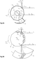
- FIGS. 3A and 3B are schematic and partial views, in cross section, of a return device 20 and a control device 40 of a servo device according to alternative embodiments.
- the return device 20 comprises N mr return mirrors 21 j with N mr > 1, for example equal to 10, like the number N Dr of return directions ⁇ D r,i ⁇ .
- the mechanical positioning device 22 comprises a rotary support 23 (not shown in the fig.3A ) on which all the deflecting mirrors ⁇ 21 j ⁇ are fixed.
- the rotating support 23 is a cylindrical structure with a polygonal section (hereinafter called a polygonal support) whose axis of rotation is here, for illustration purposes, orthogonal to the incident optical axis ⁇ L of the laser beam of power F L and the incident optical axis ⁇ c of the control laser beam F c .
- each return mirror ⁇ 21 j ⁇ has a different angle between the normal to the reflecting surface and the axis passing through the center O of rotation and the geometric center of the return mirror.
- the mirror 21 1 has a normal to the plane of angular incidence of 0° relative to the axis passing through the center of rotation, then the mirror 21 2 has an angular incidence of 0.5°, the third mirror an angular incidence of 1°, and so on.
- the number N mr of deflecting mirrors ⁇ 21 j ⁇ is even, and the mirrors are distributed along the azimuthal axis ⁇ in a regular manner.
- all the beams are contained in the plane of the polygonal support 23 (i.e. reflected in a plane perpendicular to the axis of rotation of the polygon 23). It is also possible to proceed in reverse, i.e. to assemble all the deflecting mirrors ⁇ 21 j ⁇ at the same angle and to modify the angular orientations of the mirrors ⁇ 41 k ⁇ according to the same progression (0.5°, 1°, etc.).
- each mirror ⁇ 21 j ⁇ it is also possible to orient the normals to the plane of incidence of each mirror ⁇ 21 j ⁇ according to a combination of two different angles (a first angle in the plane contained in the polygon 23 and a second angle in a perpendicular plane).
- a first angle in the plane contained in the polygon 23 and a second angle in a perpendicular plane only the mirrors ⁇ 21 j ⁇ are oriented according to this combination and the mirrors ⁇ 41 k ⁇ are all oriented in a similar way, in cooperation with the single fixed mirror 43 which has the function of returning the beam Fc in substantially the same direction as the incident direction.
- FIG. 3B describes another variant of a rotating polygonal support 23 which only includes the return mirrors ⁇ 21 j ⁇ , also used as trigger mirrors ⁇ 41 k ⁇ of the synchronization.
- the normals of the reflecting mirrors ⁇ 21 j ⁇ are oriented in a plane perpendicular to the plane of the polygonal support 23 (for example, the first mirror has an incidence of 0°, the second mirror has an incidence of 0.5° and so on).
- the reflecting mirrors ⁇ 43 l ⁇ are then placed along a circular generatrix on the spherical support 44.
- the center of the sphere is located at the intersection between the control beam F c and the line formed by the intersection between the mid-plane of the polygon 23 and the surface of the mirror.
- the mirrors ⁇ 43 l ⁇ are distributed along the circular generatrix, at adjustable positions along the path of the reflected beam (see dotted arrow on the fig. 3B ).
- the position of each mirror ⁇ 43i ⁇ along this generator also makes it possible to adjust the phase of the trigger signal s d (t) and thus the emission angle of the return direction D r,i .
- each return mirror ⁇ 21 j ⁇ comes to occupy its corresponding reference position P mr,ref,i .
- the control beam F c is then returned along the incident axis ⁇ c when the mirror 41 k is placed in correspondence with the fixed mirror 43 l , that is to say when the beam reflected by the mirror 43 l takes the same path in the opposite direction along the incident axis ⁇ c . Also, it receives the laser beam of power F L and reflects it along the associated return direction D r,i .
- the positions ⁇ P mr,ref,j ⁇ are identical in terms of positions of the geometric center of each return mirror, but differ from each other by the angular orientation of the reflecting surface. Also, the return directions ⁇ D r,i ⁇ have the same origin but are not parallel to each other.
- the servo device 30 is adapted to provide a trigger signal s d (t) to the pulse selector 12, thus authorizing the transmission of the laser beam of power F L . It comprises: a control laser source 31; a control device 40 (comprising at least one control mirror ⁇ 41 k ⁇ and a mechanical positioning device 42), a matrix photodetector 33, and an electronic trigger device 50.
- the control laser source 31 is adapted to emit a control laser beam F c .
- the beam F c can come from the injection laser source 11 (local oscillator) or from an auxiliary laser source 31.
- the control laser beam F c comes from the injection laser source 11, it is transmitted towards the control device 40.
- This same laser beam F c can be used to resynchronize the trigger signal s d (t). It has the same repetition frequency as the repetition frequency f 0 of the injection laser beam F 0 , and the phase of the trigger signal s d (t), generated by the electronic inhibitor circuit 51 of the electronic trigger device 50, is then adjustable by a time delay generator 55.
- the source injection laser 11 therefore provides, depending on the trigger signal s d (t), the injection laser beam F 0 or the control laser beam F c .
- the control laser beam F c comes from an auxiliary laser source 31 which preferably operates in continuous mode.
- the control laser beam F c is transmitted towards a rotary encoder 46 secured to the rotary support 23 to provide a trigger signal s d (t) when the rotation angle of the rotary encoder 46 crosses one or more angular thresholds defined by construction.
- Such an encoder may be optical, as illustrated in FIG. fig.8 , or magnetic.
- the threshold positions ⁇ P mr,ref,i ⁇ are respectively associated with the same optical return direction D r,th of the control laser beam F c , which is then transmitted to the matrix photodetector.
- threshold position P mc,th,1 is associated with the return threshold direction D c,th
- the threshold position P mc,th,2 also, and so on.
- threshold position P mc,th,m associated with the same return threshold direction D c,th it is meant that a control mirror 41 k , when positioned at a threshold position P mc,th,m , receives the control laser beam F c and reflects it along the same return threshold direction D c,th , which is preferably coaxial with the incident optical axis ⁇ c of the control laser beam F c (optical alignment).
- the mechanical positioning device 42 ensures the continuous rotary movement of the control mirror(s) ⁇ 41 k ⁇ . It comprises at least one support on which the deflecting mirror(s) ⁇ 21 j ⁇ are assembled, the support being set in rotary motion by a motor that can rotate at a constant or slowly variable angular rotation speed. De facto, the motor can, optionally, be controlled in rotation speed (in fact, the electronic triggering device 50 (and more precisely the electronic inhibitor circuit 51) adapts to the speed actual rotation of the rotating support 23).
- the latter are fixed to the same support as that of the deflection mirrors ⁇ 21 j ⁇ .
- the control device comprises N mc control mirrors 41 k with N mr > 1, for example equal to the number N mc of return mirrors ⁇ 21 j ⁇ .
- the mechanical positioning device 42 comprises a conical support fixed to one end of the cylindrical support 23, rotatable along the axis of rotation of the cylindrical support. All the control mirrors ⁇ 41 k ⁇ are fixed to the conical support of the device 42, and are distributed along the azimuthal axis ⁇ , preferably in a regular manner.
- the position P mc,k (t) corresponds to the position of the geometric center of the control mirror (of its reflecting surface) in the cylindrical frame (r, ⁇ ,x), as well as to the angular orientation of the control mirror ⁇ 41 k ⁇ in this same frame.
- the number N mc of control mirrors ⁇ 41 k ⁇ is even and they are distributed along the azimuthal axis ⁇ in a regular manner.
- each 41 k control mirror has a position P mc,k (t) which varies periodically over time at a frequency f sq .
- each 41 k control mirror comes to occupy a threshold position P mc,th,m . Also, it receives the control laser beam F c , and reflects it along the same return threshold direction D c,th , which is preferably coaxial with the incident optical axis ⁇ c .
- the control mirrors ⁇ 41 k ⁇ have dimensions allowing the control laser beam F c to be completely reflected. For example, this has a diameter of a few millimeters, for example equal to 2 mm.
- the control mirrors ⁇ 41 k ⁇ can here have a diameter of 5 mm to 10 mm (fixed by a mount, for example, 12.7 mm in diameter, or 1 ⁇ 2 inch).
- the fixed mirror 43 l coupled to the control mirror 41 k makes it possible to ensure the angular selectivity of the triggering.
- the fixed mirror(s) ⁇ 43 l ⁇ are preferably assembled to a goniometric support 44, or equivalent (Gimbal mount, for example), the angular position of which can be modified relative to an axis of rotation of the goniometer passing through the point of contact of the control beam F c with the control mirror 41 k .
- this makes it possible to generate a trigger signal s d (t) in phase advance on the movement of the deflection mirror 21 j , thus making it possible to compensate for any time delays in triggering of electronic and optical origins (propagation of the laser beams).
- This phase advance of mechanical origin makes it possible to obtain optimal operation of the servocontrol at the highest laser rates (kHz), i.e. a selection of a laser pulse (preferably single) from the injection laser source 11 (local oscillator) satisfying the desired conditions in terms of spatial and/or angular precision of deflection.
- the control device 40 here comprises a single fixed mirror 43 optically coupled to the control mirrors ⁇ 41 k ⁇ .
- the control laser beam F c is reflected a first time in the direction of the fixed mirror 43 by the control mirror 41 k during rotation, which reflects it in the direction of the same control mirror 41 k , which reflects it a second time.
- the fixed mirror 43 l is fixed to a goniometric support 44, the axis of rotation of which is coaxial with the incident optical axis ⁇ c .
- the control laser beam F c is returned, after the 3 reflection steps, in a direction (here not coaxial with the incident optical axis ⁇ c ) different from the return threshold direction D r,th , except when it occupies the threshold position P mc,th . Indeed, when this is the case, the control laser beam F c is returned in the return threshold direction D c,th , which is here coaxial with the incident optical axis ⁇ c .
- the control laser beam F c then has an optical alignment of its return optical path (in the direction D r,th ) with its outward optical path (in the incident optical axis ⁇ r ).
- N mf N mc .
- There are therefore here as many fixed mirrors ⁇ 43 l ⁇ as there are control mirrors ⁇ 41 k ⁇ , and there are then as many threshold positions ⁇ P mc,th,m ⁇ as there are control mirrors ⁇ 41 k ⁇ : N pth N mc .
- the fixed mirrors 43 l are all fixed to the same goniometric support 44, the axis of rotation of which is coaxial with the incident optical axis ⁇ c .
- the deflecting mirrors ⁇ 21 j ⁇ are also the control mirrors ⁇ 41 k ⁇ . Also, while a deflecting mirror ensures the reflection of the laser beam of power F L along a return direction D r,i , another return mirror ensures the function of control mirror, and reflects the control laser beam F c in the direction of the corresponding fixed mirror 43 l .
- the mechanical positioning device 42 comprises a polygonal support fixed to the polygonal support 22 of the deflection mirrors, and having an axis of rotation coaxial with that of the polygonal support 22.
- the control mirrors ⁇ 41 k ⁇ are arranged on the facets of the polygonal support 42.
- the control device 40 comprises a single fixed mirror ⁇ 43 l ⁇ optically coupled to the control mirrors ⁇ 41 k ⁇ . Also, the control mirrors ⁇ 41 k ⁇ have a single and same threshold position P mc,th . This configuration is similar to that of the fig.2A .
- the fixed mirror 43 l is fixed on a goniometric support 44, the axis of rotation of which is here orthogonal to the incident optical axis ⁇ c and passes through the threshold position P mc,th .
- the center of rotation of the goniometric support is located at the intersection between the control beam Fc and the surface of the mirror 41k when the latter occupies the threshold position.
- the deflecting mirrors ⁇ 21 j ⁇ act as control mirrors ⁇ 41 k ⁇ , so that the mechanical positioning device 22 is also that of the control device.
- This configuration is similar to that of the fig.2B .
- the fixed mirrors 43 l are all fixed to the same goniometric support 44.
- the configurations of the fig.2B and of the fig.3B where the return mirrors ⁇ 21 j ⁇ also perform the function of control mirrors ⁇ 41 k ⁇ , are advantageous, insofar as the adjustment constraints are transferred to the fixed mirrors ⁇ 43 l ⁇ , the mount of which is not subject to vibrations and accelerations, which makes it possible to improve the reliability of the laser system 1 as well as its performance in terms of spatial and/or angular return precision.
- the servo-control device 30 comprises a matrix photodetector 33. It is adapted to receive the control laser beam F c reflected by a control mirror 41 k during rotation, and to emit in response a detection signal s pd (t) representative of the movement of the control mirror 41 k .
- the detection signal s pd (t) passes through a threshold value s pd,th associated with the threshold position(s) ⁇ P mc,th,m ⁇ .
- the detection signal s pd (t) depends on the position of the laser spot of the control laser beam F c on the sensitive surface of the matrix photodetector 33, this position being a function of the position P mc,k (t) of the control mirror 41 k , during rotation, while it reflects the control laser beam F c .
- FIGS. 4A and 4B schematically and partially illustrate a matrix photodetector 33 according to one embodiment.
- it is a four-quadrant photodiode (called 4Q photodiode in the rest of the document), comprising 4 identical sensitive zones, placed symmetrically in pairs.
- the detection zones are denoted Z mn , with m and n ranging from 1 to 2, where m is the index of the rows and n that of the columns, and each provide an electrical detection signal denoted V mn .
- this choice is in no way limiting and other types of matrix detectors can be used.
- the quadrants can have a quadri-circular or square shape with a width of the order of 2.5 to 5 mm. They can be electrically separated from an intermediate non-photosensitive zone of a few tens of microns in width. Let us recall that the diameter of a laser spot can be defined from the contour where the intensity is equal to 1/e 2 of its maximum value.
- the laser spot moves on the active surface of the 4Q photodiode 33 along a horizontal axis.
- the detection signal s pd (t) can then be equal to (V 12 (t) + V 22 (t) - (V 11 (t) + V 21 (t)).
- a second signal equal to [V 11 (t) + V 12 (t)] - [V 21 (t) + V 22 (t)] can then be used to control the verticality of the laser spot.
- This signal is provided by a second adder-subtractor circuit receiving as inputs the values V 11 , V 12 , V 21 and V 22 and providing as output the signal [V 11 (t) + V 12 (t)] - [(V 21 (t) + V 22 (t)].
- This low-pass filtered signal is then communicated to the input of a positioning plate which can be actuated by a piezoelectric ceramic, for example, allowing a centered adjustment of the laser spot automatically.
- the optical assembly of the servo device 30 has here been previously adjusted so that the laser spot is positioned at the center of the sensitive surface of the 4Q photodiode 33.
- the laser spot travels along the sensitive surface of the photodiode 33 along a given axis, here the horizontal axis.
- the position P mc,k (t) of the control mirror 41 k is upstream of the corresponding threshold position P mc,th,m .
- the control laser beam F c is therefore reflected by the control device 40 and is returned in a direction different from the threshold direction of return D c,th .
- the laser spot moves over the sensitive areas Z 11 and Z 21 , so that the detection signal s pd (t) has a constant value, here negative (below the detection threshold).
- the position P mc,k (t) approaches the threshold position P mc,th,m .
- the laser spot begins to illuminate the sensitive areas Z 12 and Z 22 , so that the detection signal s pd (t) gradually increases. It increases linearly when the control laser beam F c emits continuously, or in steps when the laser emits in a pulsed manner (i.e. local oscillator).
- the control mirror 41 k occupies the threshold position P mc,th,m
- the control laser beam F c is reflected along the return threshold direction D c,th , so that the laser spot is located at a position such that the value of the detection signal s pd (t) is equal to the threshold value s pd,th .
- the threshold value s pd,th is non-zero (addition of a constant), so as to avoid untimely triggering of the pulse selector by the noise of the electronic components when the laser spot does not illuminate the 4Q 33 photodiode.
- the position P mc,k (t) of the control mirror 41 k moves away from the corresponding threshold position P mc,th,m .
- the laser spot leaves the sensitive zones Z 11 and Z 21 , and only illuminates the sensitive zones Z 12 and Z 22 .
- the detection signal s pd (t) then has a constant value, here positive (above the detection threshold).
- the servo device 30 comprises an electronic trigger device 50.
- This electronic device 50 comprises an electronic multiple pulse inhibitor circuit 51 and preferably a delay generator 55.
- the electronic inhibitor circuit 51 is adapted to emit the trigger signal s d (t) when the detection signal s pd (t) reaches said threshold value s pd,th , that is to say when a control mirror 41 k occupies the corresponding threshold position P mc,th,m , and therefore reflects the control laser beam in the return threshold direction D c,th .
- the pulse selector 12 in response to the trigger signal s d (t), transmits the laser beam of power F L which is then received by a deflection mirror 21 j while it occupies a reference position P mr,ref.i , and is therefore reflected in the corresponding deflection direction D r,i .
- the deflecting mirror is not illuminated by the laser beam of power F L except when it occupies a reference position P mr,ref.i .
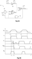
- FIG. 5A illustrates a diagram of an inhibitor electronic circuit 51 according to one embodiment. It is given here for illustrative purposes, it being understood that other configurations are possible.
- the Figure 5B is a timing diagram illustrating the operation of the electronic inhibitor circuit 51 of the fig.5A . Note here that the electronic components of the electronic circuit 51 have non-zero response times. These response times are illustrated in the fig.5B of purely illustrative manner: each response time can be more or less important and include a certain tolerance (notion of temporal jitter).
- the electronic inhibitor circuit 51 makes it possible to inhibit successive laser pulses emitted by the injection laser source 11 (local oscillator) in order to select, at the laser rate f L , preferably only one. It first comprises a comparator 52 connected to the 4Q photodiode 33. It therefore receives the detection signal s pd (t), compares the received value with the threshold value s pd,th , and provides in return a logic signal s c (t), for example 0 when s pd (t) ⁇ s pd,th and 1 when s pd (t) ⁇ s sp,th .
- the comparator 52 is chosen to have a very short response time, for example of the order of 2ns.
- the output of the comparator 52 is connected to the input I ET,a of an AND gate.
- the other input I ET,b of the AND gate is connected to the output of an XOR (exclusive OR) gate.
- This XOR gate has an input I XOR,a connected to a monostable circuit 53 (also called a monostable flip-flop) and another input connected to the output of the AND gate via a delay line 54.
- the monostable circuit 53 can be triggered on a rising edge coming from the output of the AND gate (also via the delay line 54) and is armed to logic state 1 by default, awaiting the trigger signal s d (t).
- the output of the AND gate thus forms the trigger signal s d (t), which is transmitted to the pulse selector 12 (here to the modulator 12.1 via an amplifier 12.3).
- the electronic triggering device 50 advantageously comprises a programmable delay generator 55, connected between the output of the AND logic gate and the pulse selector 12.
- the phase of the trigger signal s d (t) can thus be adjusted by the delay generator 55, so that the trigger signal s d (t) is received by the pulse selector 12 in phase with the laser pulse (to be sampled) from the injection laser source 11.
- the signal s d (t) is resynchronized with the laser pulses generated by the injection laser source 11. This can result in the laser pulse to be sampled being centered on the signal s d (t).
- the applied delay can be predefined, or even be parameterized in real time to be a function of the rotation speed of the rotating support 23 (and therefore of the laser rate f L ).
- the detection signal s pd (t) has a value lower than the threshold value s pd,th .
- the comparator 52 then provides a signal s c (t) whose value is 0, which is delivered to the input I ET,a of the AND gate.
- the monostable circuit 53 provides a signal s m (t) whose value is 1. This value is delivered to the input I XOR,a of the XOR gate.
- the AND gate delivers the value 0, since the input I ET,a is at 0.
- the output at 0 of the AND gate is looped back to the input I XOR,b of the XOR gate.
- the inputs being at 1 and 0, the XOR gate delivers the value 1.
- the AND gate can switch to the value 1, thus forming the trigger signal Sd(t).
- the detection signal s pd (t) reaches the threshold value s pd,th . Also, the comparator 52 switches to logic state 1 at time t 1,1 , which causes the AND gate to switch to logic state 1. The rising edge of the trigger signal s d (t) is therefore generated.
- the logic value 1 from the AND gate is delivered to the input I XOR,b of the XOR gate.
- the latter finds itself with its two inputs in logic state 1, which causes it to change to logic state 0 from time t 1,3 .
- the AND gate changes to logic state 0, which corresponds to the falling edge of the trigger signal s d (t).
- the time width of the trigger signal s d (t) transmitted to the pulse selector 12 is therefore essentially defined by the delay ⁇ Ir of the delay line 54 (and by the response times of the electronic components).
- the rising edge delivered by the AND gate from time t 1,2 is also delivered with the delay ⁇ Ir to the monostable circuit 53, which also switches to logic state 0 from time t 1,3 .
- the two inputs of the XOR gate are at logic state 0, so that the output of the XOR gate switches to state 0.
- the input I ET,b of the AND gate is forced to state 0, which makes it possible to block all changes of logic state that would occur at the input I ET,a , due for example to voltage oscillations at the output of the photodiode 33.
- the untimely triggering of multiple pulses can be due to power fluctuations ( pulse-to-pulse repeatability ) of the local oscillator (see voltage oscillations at the output of photodiode 33), in particular at low laser rate.
- the monostable circuit 53 remains in state 0 for a predefined duration ⁇ m , until time t 1.6 , the time for the laser spot of the control laser beam F c to leave the sensitive surface of the photodiode 33, which is the case here at time t 1.5 . Then, the monostable circuit 53 returns to logic state 1, which also resets the XOR gate. We are then in the initial configuration.
- the electronic inhibitor circuit 51 is again able to detect the passage of the threshold value in the detection signal s pd (t) and to emit in response the trigger signal Sd (t).
- the laser system 1 is effectively adapted to distribute the pulsed laser beam of power F L along several successive return directions ⁇ D r,i ⁇ , with the expected spatial return precision ⁇ D r and/or angular return precision ⁇ r , with a laser rate f L which can be high.
- the laser rate f L is controlled by the return frequency f r (here equal to the laser rate f L ) of the return device 20.
- the power laser device 10, and more precisely the pulse selector 12 is controlled by the return device 20 by means of the control device 30, and more precisely by means of the control device 40 which operates at the same return frequency f r (preferably equal to the laser rate f L ) as the return device 20.
- the return device 20 has a 'master' character while the power laser device 10 has a 'slave'character; it is the return device 20 which conditions the return frequency f r , to which the power laser device 10 is set by means of the servo device 30.
- the trigger signal s d (t) is generated so that the power laser pulse is selected and transmitted at the moment when the return mirror 21 j is in the appropriate position to reflect it in the corresponding return direction.
- the servo device 30 makes it possible to ensure that the trigger signal s d (t) is in phase with the laser pulse generated by the injection laser source 11, so as to collect it without alteration and then communicate it to the optical amplifier 13 at the desired time.
- the laser system 1 is particularly simple to produce and small in size. It consumes little energy, which makes it compatible with the requirements of industrial operation.
- FIG. 6 is a schematic and partial view of a laser system 1 according to an embodiment where the return device 20 and the control device 40 are similar to those of the fig.3A , and where the servo device 30 comprises an optoelectronic gain servo circuit 60.
- the regenerative amplifier 13.2 is here optically pumped in a pulsed manner, so as to optimize the thermal resistance and the electrical consumption.
- a gain trigger signal (hereinafter called: pumping signal s p (t)) can then be provided to the regenerative amplifier 13.2 by the optoelectronic gain control circuit 60.
- This comprises a 4Q photodiode 61 (here a 4Q photodiode), a comparator 62, a monostable circuit 63, and an amplifier 64.
- Other electrical diagrams are obviously possible.
- the transmission of the pump signal s p (t) occurs in phase advance to establish the gain of the amplifier before emission of the laser pulse by the injection laser source 11 (local oscillator).
- the pump signal s p (t) is emitted in advance by a duration of about 3 ⁇ s. Note that since most Ytterbium lasers are pumped by a continuously emitting laser, this optoelectronic gain control circuit 60 may not be used with this type of laser.
- the 4Q 61 photodiode detects the control laser beam F c once reflected by the 41 k control mirror, and provides a detection signal s pd2 (t) which is representative of the position of the 41 k control mirror during rotation.
- a comparator 62 detects the instant when the detection signal s pd2 (t) reaches the threshold value s pd,th corresponding to the optical alignment of the control laser beam F c between the forward and return paths. It then supplies the pumping signal s p (t) to a monostable circuit 63 then to a control amplifier 64. The rising edge of the pumping signal s p (t) causes the monostable circuit 63 to switch to a logic state which prevents the transmission to the amplifier 64 of new unwanted trigger signals. This ensures that only one pumping command is communicated during a laser period.
- the pump signal s p (t) is received by the regenerative amplifier 13.2 in phase advance, so that the gain is maximum when the laser pulse is received.
- the position of the photodiode 4Q 61 on the optical path of the control laser beam F c is predefined to receive the laser spot of the control beam F c before the photodiode 4Q 33 (here about 3 ⁇ s earlier).
- the laser system 1 successively distributes the laser beam of power F L along 30 return directions ⁇ D r,i ⁇ , by means of 30 return mirrors ⁇ 21 j ⁇ , at the scanning frequency f sq of 5 Hz, with a return frequency f r of 150 Hz.
- the servo device also comprises 30 control mirrors ⁇ 41 k ⁇ , which are all coupled to the same fixed mirror 43 l . It is recalled that we consider here that the laser rate f L is equal to the return frequency f r , so that a single laser pulse of power is reflected for each return direction D r,i .
- the injection laser source 11 emits the injection laser beam F 0 , of repetition frequency f 0 , for example at 80 MHz, and of power P 0 .
- the injection laser beam F 0 is received by the pulse selector 12.1, 12.2. This is formed by an electro-optical polarization modulator 12.1 (Pockels cell) followed by a polarization splitter prism 12.2.
- the polarization modulator 12.1 operates as a half-wave plate controllable in voltage: in response to the trigger signal s d (t), it switches the polarization of the light (which remains rectilinear) by 90°.
- the polarization of the laser beam F 0 remains unchanged.
- the laser beam F 0 is reflected by the polarization splitter 12.2.
- the transmitted laser beam therefore forms the control laser beam F c . It propagates in the direction of the control splitter plate 46, passes through the porthole 3 to enter the vacuum chamber.
- the porthole 3 can be treated with an antireflection deposit at the wavelength of the laser or oriented at the so-called Brewster incidence (55.5° for a silica porthole at the wavelength of 800 nm (Ti-Sa)) for the polarization of the laser, as shown in Fig. 6 . Then, this is reflected by the reflector 5 which transmits it along the optical axis ⁇ c onto the control mirror 41 k .
- the control laser beam F c is reflected by the rotating control mirror 41 k , the fixed mirror 43 l , then again by the rotating control mirror 41 k , and is finally detected by the photodiode 4Q 33 as well as by another matrix photodetector 61, here also a photodiode 4Q.
- the photodiode 4Q 33 delivers a detection signal s pd (t) whose value is a function of the position of the rotating control mirror 41 k .
- a programmable delay generator 55 is used to adjust the delay between the electrical signals and resynchronize the trigger signal s d (t) to the laser pulses generated by the injection laser source 11 (local oscillator), before communicating it to the amplifier 12.3 whose output is connected to the modulator 12.1.
- a delay generator 55 can be a commercial element (e.g. the DG535 generator from Stanford Research Systems, Inc.) or a programmed component of the CPLD (for Complex Programmable Logic Devices, in English) or FPGA (for Field Programmable Gate Array, in English) type.
- the delay generator 55 receives at the input T 0 the trigger signal s d (t), then delivers to output A with a predefined delay with respect to input T 0 . This time delay can be adjusted during the calibration of the optoelectronic chain (for example using an oscilloscope). An example of the preliminary calibration phase is detailed later.
- output B of delay generator 55 delivers another electrical pulse used to activate the logic gate located in regenerative amplifier 13.2 to input the laser pulse transmitted by pulse selector 12.1, 12.2.
- the time delay A - B can be of the order of a few nanoseconds.
- output C delivers another electrical pulse used to activate again the logic gate located in regenerative amplifier 13.2 to output the laser pulse once amplified.
- the time delay B-C can be of the order of 50-100 ns.
- the polarization modulator 12.1 When the polarization modulator 12.1 receives the trigger signal s d (t), it switches the rectilinear polarization of the incident light by 90°, so that it is then transmitted (and not reflected) by the polarization splitter 12.2. It is then transmitted towards the optical amplifier here of the CPA type formed by the elements 13.1, 13.2, 13.3. It is thus stretched in the time domain by the pulse time stretcher 13.1, amplified in the regenerative amplifier 13.2, and finally compressed in the time domain by the pulse time compressor 13.3. Note that the pulse time compressor 13.3 is placed in the vacuum enclosure. The laser beam thus amplified F L is then directed along the optical axis ⁇ r onto the deflection mirror 21 j .
- the injection laser source 11 and the regenerative amplifier 13.2 are based on Ti-Sa technology, which is characterized by high pulse energies (of the order of Joule), the laser rate f L and the return frequency f r are preferably of the order of 100 to 150 Hz, and the return mirrors ⁇ 21 j ⁇ are preferably rotating at an angular speed of between 3.3 and 5 revolutions/s for 30 return mirrors.
- the laser rate f L and the return frequency f r can reach a laser rate f L of the order of a few kilohertz, and the 30 return mirrors can be rotated at a rotation speed of up to a few tens of revolutions/s to about 200 revolutions/s (12,000 rpm).
- turbomolecular pumps rotate at speeds of rotation between 30,000 and 70,000 rpm. This is possible with Yb laser technology because the mirrors are then smaller (and therefore have less inertia) than for beams from Ti-Sa lasers.
- the adjustments are made in the atmosphere via access points made at at least two places in the enclosure, on the one hand at ground level and on the other hand, in the upper part of the gantry.
- the adjustment procedure is carried out statically (engine stopped) but the laser still operates thanks to the electronic inhibitor circuit 51, which allows the adjustments to be made in optimal laser operation.
- the rotating mechanical device 22 is then disengaged from the motor control and then locked in position for each of the angular orientations corresponding to each of the target sights (return directions).
- the injection laser source 11 local oscillator
- the optical amplifier 13 is then put into operation, as is the optical amplifier 13, at reduced power.
- the collection of the laser beam of power F L by the targets is then ensured by adjusting the normal of the mirrors ⁇ 21 j ⁇ using the 3-point mounts and by conventional positioning elements (micrometric screw displacement stage). Then, the same procedure is followed with the trigger mirrors ⁇ 41 k ⁇ and the fixed mirror(s) ⁇ 43i ⁇ . This operation is repeated for all the targets (return directions). Then, once the enclosure is closed and the pumping is carried out, the mechanical device 22 is set in motion by the motor at the prescribed rate for optimal operation of the laser system 1.
- the outputs of the various signals are then observed using a fast oscilloscope (High Definition Oscilloscope - HDO ) and the time delay durations are adjusted on the delay generator 55 in order, on the one hand, to symmetrize the trigger signal s d (t) of the laser pulse on the laser signal observed at the output of the CPA chain 13 (with the aim of minimizing the error rate in the generation of pulses) and to optimize the amplification in the regenerative amplifier 13.2.
- a fast oscilloscope High Definition Oscilloscope - HDO
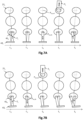
- FIGS. 7A and 7B are schematic and partial views of a 21 j deflection mirror and a 41 k control mirror rotating around the same axis of rotation, according to an embodiment similar to that of the fig.2B .
- the mirrors are rotating clockwise around the same axis of rotation.
- These figures illustrate several successive moments of rotation.
- the goniometer (not shown) on which the fixed mirror 43 l is fixed is not adjusted in order to compensate for the electronic time delay.
- this is the case on the fig.7B .
- a time delay ⁇ t r exists between the instant t 0 when the control laser beam F c is received by the control mirror 41 k (while the latter occupies the threshold position P mc,th ) then by the matrix photodetector 33, and the instant t 1 of the transmission of a laser pulse by the pulse selector and its reflection by the return mirror 21 j (while it occupies the reference position P mr,ref ).
- This delay ⁇ t r comes essentially from the response times of the electronic circuit of the matrix photodetector 33, of the electronic trigger circuit 50, and of the electronic circuit for controlling the pulse selector 12.
- the angular difference between the positions P mr,j (t 0 ) and P mr,j (t 1 ), for a time delay ⁇ t r of 30 ns for example, is of the order of 0.9 ⁇ rad, which can still meet the angular precision condition of deflection ⁇ r , for example here from one to a few tens of microradians.
- the positions P mr,j (t 0 ) and P mr,j (t 1 ) still belong to the reference position P mr,ref and guarantee that the laser pulse is reflected by the deflecting mirror 21 j in the deflecting direction D r,i with the desired precision.
- the fixed mirror 43 i is orthogonal to the vertical axis.
- the control laser beam F c is received by the control mirror 41 k (dotted line) in the direction of the fixed mirror 43 l in a first direction, then is reflected by the latter (solid line) in the direction of the mirror 41 k in another direction.
- the optical alignment of the control laser beam F c in the threshold position P mc,th is obtained at time t 0 .
- the deflection mirror 21 j is located vertically to the control mirror 41 k and the fixed mirror 43 l . However, it is at time t 1 that it receives the laser pulse to reflect it in a deflection direction.
- the reference position P mr,ref is then passed. The condition on the spatial precision of deflection can however still be verified, depending on the deflection frequency f r and therefore the laser rate f L .
- this time delay ⁇ t r can lead to no longer meeting the desired condition on the spatial return precision ⁇ D r , (or the angular return precision ⁇ r ) in particular when the laser rate f L is higher, as is the case for example for f L equal to 6 kHz.
- the angular speed ⁇ sq is 2 ⁇ 200 Hz, or equal to approximately 1250 radii.
- the angular difference between the positions P mr,j (t 0 ) and P mr,j (t 1 ), for a time delay ⁇ t r of 30 ns for example, is then of the order of 37 ⁇ rad, which is here greater than the desired angular return precision ⁇ r of 10 ⁇ rad.
- control mirror 41 k reaches its threshold position P mc,th in phase advance, before the deflecting mirror 21 j reaches its reference position P mr,ref .
- This phase advance of the control mirror 41 k with respect to the deflection mirror 21 j makes it possible to compensate for the time delay ⁇ t r , so that the laser beam of power F L is reflected by the deflection mirror 21 j (which effectively occupies the reference position P mr,ref,i ) in the deflection direction D r,i with the desired angular deflection precision ⁇ r , even though the deflection frequency f r and therefore the laser rate f L can be high.
- the fixed mirror 43 i is inclined relative to the vertical axis, due to an adjustment of the goniometer (not shown).
- the time shift here corresponds to t 0 - t -1 .
- a return frequency f r of 6 kHz (corresponding to a rotation of 1250 rad/s)
- an inclination of the fixed mirror of 37 ⁇ rad, in the counterclockwise direction, between the normal to the reflecting surface and the vertical axis makes it possible to obtain a phase advance of 30 ns.
- This inclination corresponds to a shift of 30 ⁇ m on a goniometric radius of 80 cm.
- this shift can be pre-set mechanically, for example by means of a micrometer screw, or adjustable in real time, for example by means of a piezoelectric actuator.
- the control laser beam F c is received by the control mirror 41 k at the threshold position P mc,th at time t -1 , and the laser beam of power F L is then received by the deflection mirror 21 j at time t 0 while it precisely occupies the reference position P mr,ref (here located vertically to the control mirror 41 k ).
- the spatial precision of the deflection is then particularly high, even though the deflection frequency f r and therefore the laser rate f L are high.
- the laser system 1 can also be used with a return frequency f r and therefore a variable laser rate f L.
- the phase advance of the triggering of the pulse selector 12 can be adjusted by means of a presetting of the goniometric support, which can optionally be adjusted by a delay applied by the delay generator. programmable 55. Advantage is thus taken of the fact that the return device 20 has a 'master' character and that the power laser device 10 has a 'slave' character due to the servo device 30.
- ⁇ ⁇ nom ⁇ ⁇ t g
- ⁇ nom the nominal angular speed at which the goniometric angle ⁇ was preset.
- ⁇ t sup ⁇ t g + ⁇ (1/ ⁇ eff - 1/ ⁇ nom ).
- FIG 8 is a schematic and partial view of a laser system 1 according to an alternative embodiment, which differs from that of the fig.6 essentially in that, on the one hand, the control laser beam F c is emitted by a control laser source 31 separate from the injection laser source 11, and on the other hand, the control device 40 comprises a rotary encoder 46 secured to the rotary support 23.
- the control laser source 31 can obviously be used in the context of the variants of the fig.2A, 2B , 3A and 3B .
- There fig.8 also includes a front view of the rotary encoder 46, located here on the upstream face of the rotary support 23.
- the control laser source 31 is adapted to emit the control laser beam F c , which therefore does not come from the injection laser source 11 (local oscillator). It is transmitted towards the control device 40, and here passes through a semi-reflecting plate 4, a focusing lens, and a porthole 3 (oriented here at the Brewster incidence of 55°).
- the laser beam F c is preferably a continuous beam.
- the control device 40 comprises a rotary encoder 46, here an optical encoder, assembled to the rotary support 23 of the return device 20, so that the encoder 46 is rotating when the support 23 is rotating.
- the return device 20 is identical or similar to that of the fig.2A and 2B , and the rotary encoder 46 is located on the upstream face of the rotary support 23.
- the rotary encoder 46 is formed of a reflective surface 46.1, reflective at the wavelength of the control laser beam F c , and which extends along the circumference of the upstream face of the rotary support 23.
- Non-reflecting zones 46.2 here holes, are regularly distributed along the reflective surface 46.1, along the circumference of the upstream face of the rotating support 23, at a rate of 1 hole 46.2 for 1 return direction D r,i .
- Each hole 46.2 is separated from the neighboring holes by the reflecting surface 46.1.
- the holes 46.2 are positioned along a circumferential line which is traveled by the laser beam F c as the support 23 rotates.
- the holes 46.2 may have a diameter of 50 to 100 ⁇ m for a laser spot of the laser beam F c with a diameter of approximately 30 ⁇ m.
- the non-reflecting areas 46.2 may be holes or lines.
- the holes 46.2 may have a diameter of 50 ⁇ m to 100 ⁇ m, or even more.
- the lines may have a width of the same order. Triggering by a succession of lines is probably more reliable than by a succession of holes (independence vs. axial displacement of the device).
- the laser beam F c is reflected by the reflecting surface 46.2 of the rotary encoder 46, then is returned to a photodiode 33 (for example of the PIN type).
- the electric current generated by the photodiode 33 is here transformed into electric voltage by a transimpedance circuit 56.
- s c (t) When a hole 46.2 arrives in correspondence with the laser beam F c , the latter is no longer reflected, and the optical power received by the photodiode 33 decreases sharply, then falling below a predefined threshold.
- the electrical signal, called here s c (t), is here reformatted into positive logic by an inverting amplifier 57: it then corresponds to a rising edge ( leading edge, in English).
- This electrical signal s c (t) is here communicated to the trigger input of the laser pumping circuit to regenerate the gain of the regenerative amplifier 13.2.
- this same electrical signal s c (t) is communicated to a delay generator 58 which imposes a predefined time delay, for example of the order of 3 ⁇ s for a Ti-Sa laser, the time for the population inversion to be effective.
- the electrical signal s c (t) therefore appears at the input of an AND logic cell to arm the synchronization.
- the first laser pulse generated by the injection laser source 11 is detected by a second photodiode 59, which then switches the logic output of the AND cell (here to 1) and triggers the emission of the trigger signal s d (t), and therefore the sampling of the laser pulse according to the timing diagram adapted to the electronic circuit (taking into account the optical and electronic propagation time delays), as described in the fig.5B .
- the following laser pulses are blocked by the electronic inhibitor circuit 51.
- the trigger signal s d (t) is shifted again by the delay generator 55, to open the amplification cell of the regenerative amplifier 13.2, as previously described.
- This optoelectronic assembly therefore allows selection without alteration of a laser pulse emitted by the injection laser source 11 when the rotary encoder 46 is in the position angular adapted to a return of the laser beam of power F L in the desired return direction D r,i .
- the laser source 31 is placed outside the vacuum enclosure to facilitate its adjustment and maintenance, as well as its thermalization.
Landscapes
- Physics & Mathematics (AREA)
- Optics & Photonics (AREA)
- Engineering & Computer Science (AREA)
- Electromagnetism (AREA)
- Plasma & Fusion (AREA)
- General Physics & Mathematics (AREA)
- Mechanical Engineering (AREA)
- Lasers (AREA)
Applications Claiming Priority (1)
| Application Number | Priority Date | Filing Date | Title |
|---|---|---|---|
| FR2307211A FR3150917A1 (fr) | 2023-07-06 | 2023-07-06 | Système laser adapté à distribuer un faisceau laser impulsionnel de puissance suivant plusieurs directions successives |
Publications (2)
| Publication Number | Publication Date |
|---|---|
| EP4489235A2 true EP4489235A2 (de) | 2025-01-08 |
| EP4489235A3 EP4489235A3 (de) | 2025-05-07 |
Family
ID=88838808
Family Applications (1)
| Application Number | Title | Priority Date | Filing Date |
|---|---|---|---|
| EP24186536.9A Pending EP4489235A3 (de) | 2023-07-06 | 2024-07-04 | Optische schaltung und sequentielle räumliche verteilung eines gepulsten leistungslaserstrahls mit deterministischer servosteuerung |
Country Status (2)
| Country | Link |
|---|---|
| EP (1) | EP4489235A3 (de) |
| FR (1) | FR3150917A1 (de) |
Citations (5)
| Publication number | Priority date | Publication date | Assignee | Title |
|---|---|---|---|---|
| FR2608786A1 (fr) | 1986-12-22 | 1988-06-24 | Gen Electric | Appareil et procede pour diriger un faisceau laser |
| EP0390662A1 (de) | 1989-03-31 | 1990-10-03 | Thomson-Csf | Hochleistungs-Laser mit Steuerung der Richtung der Ausgangsstrahlung |
| WO1993006641A1 (fr) | 1991-09-27 | 1993-04-01 | Thomson-Csf | Laser de puissance a deflexion |
| US20020126948A1 (en) | 2001-03-06 | 2002-09-12 | Sitek, Inc. | Translational optical shutter for a fiber optic switch |
| US20050087295A1 (en) | 2001-11-07 | 2005-04-28 | Mlt Micro Laser Technology Gmbh | Device for substrate treatment by means of laser radiation |
Family Cites Families (3)
| Publication number | Priority date | Publication date | Assignee | Title |
|---|---|---|---|---|
| DE19937267A1 (de) * | 1999-08-06 | 2001-02-15 | Baasel Carl Lasertech | Vorrichtung zur Behandlung eines Substrates mittels Laserstrahlung |
| JP6651768B2 (ja) * | 2015-09-28 | 2020-02-19 | 株式会社ニコン | パターン描画装置 |
| FR3128140B1 (fr) * | 2021-10-19 | 2024-09-27 | Steelemat S A R L | Dispositif de test non destructif à ultrasons hybride Transducteurs électromagnétiques acoustiques/Laser à assemblage optique rotatif monolithique de transmetteurs laser agiles matriciels pour le contrôle d'objets métallurgiques |
-
2023
- 2023-07-06 FR FR2307211A patent/FR3150917A1/fr active Pending
-
2024
- 2024-07-04 EP EP24186536.9A patent/EP4489235A3/de active Pending
Patent Citations (5)
| Publication number | Priority date | Publication date | Assignee | Title |
|---|---|---|---|---|
| FR2608786A1 (fr) | 1986-12-22 | 1988-06-24 | Gen Electric | Appareil et procede pour diriger un faisceau laser |
| EP0390662A1 (de) | 1989-03-31 | 1990-10-03 | Thomson-Csf | Hochleistungs-Laser mit Steuerung der Richtung der Ausgangsstrahlung |
| WO1993006641A1 (fr) | 1991-09-27 | 1993-04-01 | Thomson-Csf | Laser de puissance a deflexion |
| US20020126948A1 (en) | 2001-03-06 | 2002-09-12 | Sitek, Inc. | Translational optical shutter for a fiber optic switch |
| US20050087295A1 (en) | 2001-11-07 | 2005-04-28 | Mlt Micro Laser Technology Gmbh | Device for substrate treatment by means of laser radiation |
Also Published As
| Publication number | Publication date |
|---|---|
| FR3150917A1 (fr) | 2025-01-10 |
| EP4489235A3 (de) | 2025-05-07 |
Similar Documents
| Publication | Publication Date | Title |
|---|---|---|
| EP0597771A1 (de) | Überwachungseinrichtung zur optischer Bundelzentrierung, Verwendung zur Bundeleinführung in optische Faser | |
| EP1449020B1 (de) | Einrichtung zur schnellen sektoriellen oder panoramischen überwachung ohne anscheinende bewegung | |
| EP1052476B1 (de) | Verfahren und Vorrichtung zum Feststellen von Fluchtungsfehlern eines optischen Instruments | |
| EP0515252A1 (de) | Vorrichtung zum Erfassen der augenblicklichen Winkeleinstellung eines beweglichen Objekts und opto-mechanisches System mit solcher Vorrichtung | |
| FR2861851A1 (fr) | Dispositif de detection optique d'un objet distant | |
| FR2625850A1 (fr) | Appareil optique a laser | |
| FR2505505A1 (fr) | Dispositif laser pour detecter et neutraliser l'optique d'un appareil de reperage adverse | |
| BE1027700B1 (fr) | Dispositif pour un système optique d’usinage laser | |
| EP4489235A2 (de) | Optische schaltung und sequentielle räumliche verteilung eines gepulsten leistungslaserstrahls mit deterministischer servosteuerung | |
| EP0559878A1 (de) | Hochleistungs-ablenkungslaser. | |
| EP0702246A1 (de) | Tragbares Gerät zum Messen der Rückstreuung von Licht | |
| EP0035423A2 (de) | Vorrichtung zur Detektion und Lokalisation von Oberflächendiskontinuitäten mit einem Lichtbündel | |
| EP0038297A1 (de) | Verfahren zum Entgräten eines scharfen Instruments, Ausführung des Verfahrens und durch dieses Verfahren erhaltenes scharfes Instrument | |
| WO2009056588A1 (fr) | Source laser comportant un dispositif de balayage angulaire | |
| WO2024126592A1 (fr) | Dispositif optique dispersif et système laser à impulsions brèves comprenant un tel dispositif optique dispersif | |
| EP3278139B1 (de) | Abbildungsvorrichtung und entsprechendes abbildungsverfahren | |
| EP0511361B1 (de) | Vorrichtung zur stabilisierung der reflektivität eines phasenkonjugierungsspiegels für hohe wiederrholungsfrequenz der mit stimulierter brillouin-streuung wirkt | |
| FR2662515A1 (fr) | Dispositif optique permettant d'imprimer a un faisceau lumineux collimate un mouvement de translation. | |
| EP1978376B1 (de) | Aktiver Überwachungskopf einer Umgebung mit Strahlschwenkung vor Ort, Überwachungssystem, das mit einem solchen Kopf ausgestattet ist, und Verfahren zur Anwendung dieses Kopfs und des Systems | |
| WO2016024069A1 (fr) | Dispositif d'usinage par faisceau laser d'un trou a conicite controlée avec un module afocal déplaçable | |
| FR2610421A1 (fr) | Dispositif de deflexion de faisceau et imprimante a faisceau laser l'utilisant | |
| WO2026057664A1 (fr) | Système de distribution ou recombinaison de faisceaux lasers | |
| FR2730818A1 (fr) | Telemetre laser a effet larsen comportant notamment une optique unique d'emission et de reception | |
| WO2020221823A1 (fr) | Systeme d'alignement d'un dispositif de traitement thermique et son fonctionnement | |
| EP0336793B1 (de) | Vorrichtung zur Ortung eines Objektes durch Abtasten des Objektes mit einem Lichtstrahl |
Legal Events
| Date | Code | Title | Description |
|---|---|---|---|
| PUAI | Public reference made under article 153(3) epc to a published international application that has entered the european phase |
Free format text: ORIGINAL CODE: 0009012 |
|
| STAA | Information on the status of an ep patent application or granted ep patent |
Free format text: STATUS: REQUEST FOR EXAMINATION WAS MADE |
|
| 17P | Request for examination filed |
Effective date: 20240704 |
|
| AK | Designated contracting states |
Kind code of ref document: A2 Designated state(s): AL AT BE BG CH CY CZ DE DK EE ES FI FR GB GR HR HU IE IS IT LI LT LU LV MC ME MK MT NL NO PL PT RO RS SE SI SK SM TR |
|
| REG | Reference to a national code |
Ref country code: DE Ref legal event code: R079 Free format text: PREVIOUS MAIN CLASS: H01S0005026000 Ipc: B23K0026067000 |
|
| PUAL | Search report despatched |
Free format text: ORIGINAL CODE: 0009013 |
|
| AK | Designated contracting states |
Kind code of ref document: A3 Designated state(s): AL AT BE BG CH CY CZ DE DK EE ES FI FR GB GR HR HU IE IS IT LI LT LU LV MC ME MK MT NL NO PL PT RO RS SE SI SK SM TR |
|
| RIC1 | Information provided on ipc code assigned before grant |
Ipc: H01S 5/026 20060101ALI20250401BHEP Ipc: B23K 26/067 20060101AFI20250401BHEP |