EP4489230A2 - System und verfahren zum anbringen, routen und verbergen von kabeln auf einem lastentragenden gurtband - Google Patents
System und verfahren zum anbringen, routen und verbergen von kabeln auf einem lastentragenden gurtband Download PDFInfo
- Publication number
- EP4489230A2 EP4489230A2 EP24214557.1A EP24214557A EP4489230A2 EP 4489230 A2 EP4489230 A2 EP 4489230A2 EP 24214557 A EP24214557 A EP 24214557A EP 4489230 A2 EP4489230 A2 EP 4489230A2
- Authority
- EP
- European Patent Office
- Prior art keywords
- tabs
- strip
- molle
- coupling
- connector
- Prior art date
- Legal status (The legal status is an assumption and is not a legal conclusion. Google has not performed a legal analysis and makes no representation as to the accuracy of the status listed.)
- Pending
Links
Images








Classifications
-
- A—HUMAN NECESSITIES
- A45—HAND OR TRAVELLING ARTICLES
- A45F—TRAVELLING OR CAMP EQUIPMENT: SACKS OR PACKS CARRIED ON THE BODY
- A45F5/00—Holders or carriers for hand articles; Holders or carriers for use while travelling or camping
- A45F5/02—Fastening articles to the garment
-
- F—MECHANICAL ENGINEERING; LIGHTING; HEATING; WEAPONS; BLASTING
- F41—WEAPONS
- F41C—SMALLARMS, e.g. PISTOLS, RIFLES; ACCESSORIES THEREFOR
- F41C33/00—Means for wearing or carrying smallarms
- F41C33/02—Holsters, i.e. cases for pistols having means for being carried or worn, e.g. at the belt or under the arm
- F41C33/04—Special attachments therefor
- F41C33/041—Special attachments therefor for connecting a holster to a belt, webbing or other object
-
- F—MECHANICAL ENGINEERING; LIGHTING; HEATING; WEAPONS; BLASTING
- F41—WEAPONS
- F41H—ARMOUR; ARMOURED TURRETS; ARMOURED OR ARMED VEHICLES; MEANS OF ATTACK OR DEFENCE, e.g. CAMOUFLAGE, IN GENERAL
- F41H1/00—Personal protection gear
- F41H1/02—Armoured or projectile- or missile-resistant garments; Composite protection fabrics
-
- H—ELECTRICITY
- H01—ELECTRIC ELEMENTS
- H01R—ELECTRICALLY-CONDUCTIVE CONNECTIONS; STRUCTURAL ASSOCIATIONS OF A PLURALITY OF MUTUALLY-INSULATED ELECTRICAL CONNECTING ELEMENTS; COUPLING DEVICES; CURRENT COLLECTORS
- H01R13/00—Details of coupling devices of the kinds covered by groups H01R12/70 or H01R24/00 - H01R33/00
- H01R13/62—Means for facilitating engagement or disengagement of coupling parts or for holding them in engagement
- H01R13/629—Additional means for facilitating engagement or disengagement of coupling parts, e.g. aligning or guiding means, levers, gas pressure electrical locking indicators, manufacturing tolerances
- H01R13/633—Additional means for facilitating engagement or disengagement of coupling parts, e.g. aligning or guiding means, levers, gas pressure electrical locking indicators, manufacturing tolerances for disengagement only
- H01R13/635—Additional means for facilitating engagement or disengagement of coupling parts, e.g. aligning or guiding means, levers, gas pressure electrical locking indicators, manufacturing tolerances for disengagement only by mechanical pressure, e.g. spring force
-
- H—ELECTRICITY
- H01—ELECTRIC ELEMENTS
- H01R—ELECTRICALLY-CONDUCTIVE CONNECTIONS; STRUCTURAL ASSOCIATIONS OF A PLURALITY OF MUTUALLY-INSULATED ELECTRICAL CONNECTING ELEMENTS; COUPLING DEVICES; CURRENT COLLECTORS
- H01R13/00—Details of coupling devices of the kinds covered by groups H01R12/70 or H01R24/00 - H01R33/00
- H01R13/73—Means for mounting coupling parts to apparatus or structures, e.g. to a wall
Definitions
- the present invention relates to a system for and method of securely and recoverably attaching and routing cables, wires or tubing onto the outer surface of a garment or item that employs a Pouch Attachment Ladder System (PALS) or Modular Lightweight Load-carrying Equipment (MOLLE) webbing, such as a military load-carriage vest or bag.
- PALS Pouch Attachment Ladder System
- MOLLE Modular Lightweight Load-carrying Equipment
- PALS Pouch Attachment Ladder System
- MOLLE Modular Lightweight Load-carrying Equipment
- This provides for a grid of webbing loops, into which vertical strips of webbing, disposed upon the mating face of a pouch, holster and the like may be interwoven to effect a secure, but recoverable attachment.
- MOLLE or PALS has become the de-facto accessory attachment method for the vast majority of contemporary military and law-enforcement load-carriage garments.
- MOLLE is used to refer to both MOLLE and PALS.
- MOLLE webbing is used to refer to the webbing that is disposed upon the surface of an article such as a garment or bag in the aforementioned arrangement.
- MOLLE loop is used to refer to that portion of MOLLE webbing that extends between the vertical lines of stitching at a 38mm or 1.5" interval and so forms a single pliable loop upon the surface of an article.
- Modern war fighters and law enforcement personnel also carry an increasing number of electrical and electronic devices in the course of their duties, such as radios, navigation devices, computing devices, sensors, as so on. It is advantageous to interconnect these devices, such that they might share data and electrical power, sometimes termed a Personal Area Network or PAN. This is customarily achieved by the use of interconnecting cables between the various devices.
- PAN Personal Area Network
- conventional cables suffer from a number of drawbacks when used for interconnections between body-worn devices: conventional cables can be relatively rigid, leading to protruding loops of cable that pose a risk of snagging; loose cables can easily become tangled with themselves or other cables; loose cables can interfere with opening pouches, operating equipment and donning and doffing garments; stray cables can be uncomfortable for the wearer, causing pressure points or chafing when they stray under backpack straps, for instance.
- the flexible strip is advantageously flexible so as to be foldable on itself. In practice, this enables the strip to be folded so as to change direction and is sufficiently foldable that facing folded surfaces are preferably able to touch one another. This keeps the connector flat even when folded.
- the body portion is substantially flat.
- the body portion may be substantially planar and the first and second arrays of tabs substantially co-planar with the body portion.
- the body portion includes one or more openings or slits for the passage of a component therethrough.
- the body portion has a width of 2.5 centimetres.
- the tabs have a pitch either individually or in a plurality thereof of 2.5 to 3.8 centimetres.
- the connector or system may include a fixation frame connectable between MOLLE loops and having a connector portion to which a coupling element of the strip can be releasably attached.
- the fixation frame preferably includes slotted feet configured to be coupled into associated MOLLE loops.
- the slotted feet advantageously have slots disposed orthogonally to one another.
- the frame is preferably rotationally symmetrical so that it can be fitted to MOLLE webbing in different orientations as disclosed below.
- the fixation frame may constitute an individual and distinct aspect of the invention.
- the connector may be transversally separable into sections having at least one set of laterally opposing tabs.
- the connector or system may include an insertion tool including an interior configured to receive the flexible connector with the tabs deflected by the tool, the tool being configured to be insertable in a MOLLE loop with the elongate strip fitted in the tool, the tabs engaging with the MOLLE loop on removal of the tool.
- the tool includes a base member and first and second upstanding flanges tapering towards one another from the base member, the flanges being configured to deflect the tabs towards one another when the strip is inserted into the tool.
- the connector is most preferably sized to fit between rows of standard MOLLE webbing and/or within columns of standard MOLLE webbing loops.
- body-worn cables are provided with a series of laterally disposed, opposing pairs of flexible tabs, that are so designed as to be tucked under MOLLE loops and thus serve to anchor the cables along their lengths to the surface of a load-carriage garment in a desired routing.
- a cable is provided with opposing pairs of laterally disposed flexible tabs, the tabs of an opposing pair being spaced apart by 25mm or 1", such that when the cable is to be routed horizontally, it may be anchored both from above and below by two adjacent rows of MOLLE webbing.
- the tabs may advantageously be provided as formed and/or cut from the outer material of the cable itself.
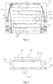
- the sheath 241 and tabs 242 in Figure 10 may be fabricated separately from the flat cable, and applied retrospectively as described above for the embodiment shown in Figure 9 .
- the sheath 241 may alternatively be formed integrally with the flat cable and constitute the outer layer or layers of the flat cable 243, formed by moulding, cutting, extruding and so on as described elsewhere herein.
- the embodiment shown in Figure 10 therefore offers the advantage of reduced weight and bulk compared to the other embodiments described herein, as the material that comprises the sheath or strip can also perform some of the functions necessary to the cable itself, such as screening, environmental or abrasion protection.
- a conventional cable of circular cross-section, with bundled rather than coplanar conductors may also be provided with lateral opposing tabs in a similar fashion to that described for the embodiment of Figure 10 .
- Such a cable is co-extruded with its outer insulation layer in the fashion known in the art, with the addition of a pair of opposing lateral wings (or wing sets) formed through the shape of the extrusion die.
- the tabs described herein are then formed by passing the lateral wings through a pair of rollers that form or cut the shape of the tabs as the cable is extruded.
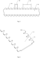
- the strip 310 is flexible enough to be folded on itself, with preferably the folded facing surfaces of the MOLLE webbing being in contact with one another.
- the connector is preferably flexible enough so as to remain substantially flat when folded. This is a preferred characteristic of all embodiments of flexible strip and connector disclosed and envisaged in this application.
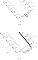
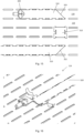
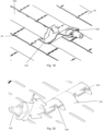
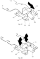
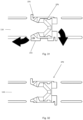
- Figures 16-19 show the embodiment of connectors shown in Figure 15 being fitted to the MOLLE webbing, the arrows depicting how the connector can be fitted and attached to MOLLE webbing.
- the tabs 312 are preferably flexible enough that they can be folded into slots in the MOLLE webbing or underneath the strips 18 of MOLLE webbing simply with hand force.
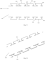
- Figure 20 shows another example of fitting of the connector to MOLLE webbing 116.
- the strip 310 is folded longitudinally so that the tab 312 lay the same side, and are preferably together with the half width of strip 310 narrower than the aperture between MOLLE loops, enabling the strip 310 to be pulled through the loops prior to unfolding and connecting via the tabs 312.
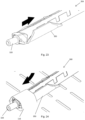
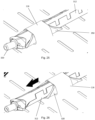
- FIGS 21-23 show an insertion tool 350 that can be used in fitting the connector to MOLLE webbing.
- the tool 350 includes a base 352 and upstanding flanges 354 which taper towards one another from the base 352.
- a connector can be fitted into the tool 350, as depicted in Figures 22 and 23 , and in such a manner that the tabs 312 are deflected by the flanges 354, 356.
- the width of the base 352 is preferably around the same as the width of the elongate strip 310 of the connector, although it may be narrower.
- FIGS 27-33 show a fixation element 370 that can be used for fixing the end of the connector 300 to MOLLE webbing.
- the fixation element 370 includes, in this embodiment, four feet 372 having slots 374 therein which are orthogonally arranged with respect to one another, as will be apparent in particular from Figures 29 and 30 .
- the feet and connector and sized to be able to fit within the slots 118 of MOLLE webbing in the manner shown. They include a fitting 376 to which, in this example, the coupling element 320 can be attached.
- a plurality of the fixation elements could be fitted to MOLLE webbing, as shown in Figure 33 , for example.
- the fixation elements 370 are preferably designed with rotational symmetry, such that they can be attached to the MOLLE webbing 18 in four differing orientations, allowing four directions of insertion for the coupling element 320.
- the surface finish of the strip or cable may be advantageous for the surface finish of the strip or cable to match the surface finish of the garment to which attachment is sought, in order to minimise the visual impact of the strip or cable, and/or reduce its visible and/or infrared detection signature.
- the strip or cable may be provided with an outer surface that is printed, dyed, painted, or laminated to match the garment's printed or dyed colour or camouflage pattern.
- the strip may be provided with an outer surface that is composed of the same textile material as the garment.
- the strip or cable may be provided with a composition and/or surface finish that serves to better radiate, conduct or convect away heat generated by the cable, in order to reduce its infrared or thermal detection signature.
- the surface might, for example, comprise a heavily textured or finned surface, whilst the composition might, for example, be of a highly thermally conductive material.
- an embodiment of the invention is attached permanently to a terminating electrical connector or connectors at one or both ends, then one or both of those electrical connectors is preferably sufficiently small in transverse cross-section to pass through a MOLLE loop in order to route the cable in a vertical orientation. That is, one or both of the electrical connectors preferably has a circumference of less than 75mm or 3".
- the circumference of the electrical connector(s) is less than 50mm or 2", to pass through a laser-cut MOLLE slot.
Landscapes
- Engineering & Computer Science (AREA)
- General Engineering & Computer Science (AREA)
- Details Of Indoor Wiring (AREA)
- Professional, Industrial, Or Sporting Protective Garments (AREA)
- Outer Garments And Coats (AREA)
- Details Of Connecting Devices For Male And Female Coupling (AREA)
Applications Claiming Priority (3)
| Application Number | Priority Date | Filing Date | Title |
|---|---|---|---|
| GBGB1902684.8A GB201902684D0 (en) | 2019-02-28 | 2019-02-28 | System and method for attaching, routing and concealing cables on load carrying webbing |
| EP19845776.4A EP3930534B1 (de) | 2019-02-28 | 2019-12-19 | System und verfahren zur befestigung, führung und verdeckung von kabeln auf einem lasttragenden gewebe |
| PCT/GB2019/053632 WO2020174204A1 (en) | 2019-02-28 | 2019-12-19 | System and method for attaching, routing and concealing cables on load carrying webbing |
Related Parent Applications (2)
| Application Number | Title | Priority Date | Filing Date |
|---|---|---|---|
| EP19845776.4A Division EP3930534B1 (de) | 2019-02-28 | 2019-12-19 | System und verfahren zur befestigung, führung und verdeckung von kabeln auf einem lasttragenden gewebe |
| EP19845776.4A Division-Into EP3930534B1 (de) | 2019-02-28 | 2019-12-19 | System und verfahren zur befestigung, führung und verdeckung von kabeln auf einem lasttragenden gewebe |
Publications (2)
| Publication Number | Publication Date |
|---|---|
| EP4489230A2 true EP4489230A2 (de) | 2025-01-08 |
| EP4489230A3 EP4489230A3 (de) | 2025-04-16 |
Family
ID=66377362
Family Applications (2)
| Application Number | Title | Priority Date | Filing Date |
|---|---|---|---|
| EP24214557.1A Pending EP4489230A3 (de) | 2019-02-28 | 2019-12-19 | System und verfahren zum anbringen, routen und verbergen von kabeln auf einem lastentragenden gurtband |
| EP19845776.4A Active EP3930534B1 (de) | 2019-02-28 | 2019-12-19 | System und verfahren zur befestigung, führung und verdeckung von kabeln auf einem lasttragenden gewebe |
Family Applications After (1)
| Application Number | Title | Priority Date | Filing Date |
|---|---|---|---|
| EP19845776.4A Active EP3930534B1 (de) | 2019-02-28 | 2019-12-19 | System und verfahren zur befestigung, führung und verdeckung von kabeln auf einem lasttragenden gewebe |
Country Status (6)
| Country | Link |
|---|---|
| US (1) | US11262161B2 (de) |
| EP (2) | EP4489230A3 (de) |
| AU (1) | AU2019430944B2 (de) |
| CA (1) | CA3130597A1 (de) |
| GB (1) | GB201902684D0 (de) |
| WO (1) | WO2020174204A1 (de) |
Families Citing this family (5)
| Publication number | Priority date | Publication date | Assignee | Title |
|---|---|---|---|---|
| US11944184B2 (en) * | 2020-06-10 | 2024-04-02 | Crosier Products, LLC | Systems and methods for attaching patches to equipment |
| US12320610B2 (en) * | 2021-06-19 | 2025-06-03 | Shanyao Lee | Cover kit for firearm handguard |
| US12082366B2 (en) * | 2021-06-21 | 2024-09-03 | Shanyao Lee | Cable management assembly for firearm |
| EP4614743A1 (de) * | 2024-03-06 | 2025-09-10 | Stirling Moulded Composites Limited | Elektrisches verbindungselement und herstellungsverfahren |
| GB202403265D0 (en) * | 2024-03-06 | 2024-04-17 | Stirling Moulded Composites Ltd | Electrical connection member and method of manufacture |
Citations (7)
| Publication number | Priority date | Publication date | Assignee | Title |
|---|---|---|---|---|
| US5724707A (en) | 1996-06-17 | 1998-03-10 | The United States Of America As Represented By The Secretary Of The Army | Interlock attaching strap system |
| US20120045929A1 (en) | 2010-08-23 | 2012-02-23 | Richard Streeter | Pals compliant routing system |
| US8297562B1 (en) | 2006-10-03 | 2012-10-30 | Alliant Techsystems Inc. | Universal mounting platform |
| WO2013022976A1 (en) | 2011-08-08 | 2013-02-14 | Firstspear | Light weight modular pouch attachment system and method |
| US20130192887A1 (en) | 2012-01-27 | 2013-08-01 | Hitachi Cable, Ltd. | Flat wiring material and mounting body using the same |
| US20150182011A1 (en) | 2013-12-27 | 2015-07-02 | Patrick F. Mccrone | Web panel attachment system |
| GB2525210A (en) | 2014-04-15 | 2015-10-21 | Solo Int Ltd | Cruciform buckle system |
Family Cites Families (4)
| Publication number | Priority date | Publication date | Assignee | Title |
|---|---|---|---|---|
| JPH09320689A (ja) * | 1996-05-28 | 1997-12-12 | Yoshihiko Yamaji | 差し込みプラグ |
| US8079503B1 (en) * | 2006-02-08 | 2011-12-20 | Blackhawk Industries Product Group Unlimited Llc | Modular equipment coupler |
| JP5887581B2 (ja) * | 2011-10-18 | 2016-03-16 | 善四郎 吉村 | コンセントプラグ及びコンセントプラグの補助具 |
| CN204011961U (zh) * | 2014-07-22 | 2014-12-10 | 佳木斯大学 | 插座插头辅助拔出工具 |
-
2019
- 2019-02-28 GB GBGB1902684.8A patent/GB201902684D0/en not_active Ceased
- 2019-12-19 WO PCT/GB2019/053632 patent/WO2020174204A1/en not_active Ceased
- 2019-12-19 US US16/980,694 patent/US11262161B2/en active Active
- 2019-12-19 EP EP24214557.1A patent/EP4489230A3/de active Pending
- 2019-12-19 CA CA3130597A patent/CA3130597A1/en active Pending
- 2019-12-19 EP EP19845776.4A patent/EP3930534B1/de active Active
- 2019-12-19 AU AU2019430944A patent/AU2019430944B2/en active Active
Patent Citations (8)
| Publication number | Priority date | Publication date | Assignee | Title |
|---|---|---|---|---|
| US5724707A (en) | 1996-06-17 | 1998-03-10 | The United States Of America As Represented By The Secretary Of The Army | Interlock attaching strap system |
| US8297562B1 (en) | 2006-10-03 | 2012-10-30 | Alliant Techsystems Inc. | Universal mounting platform |
| US20120045929A1 (en) | 2010-08-23 | 2012-02-23 | Richard Streeter | Pals compliant routing system |
| US8785778B2 (en) | 2010-08-23 | 2014-07-22 | Foster-Miller, Inc. | PALS compliant routing system |
| WO2013022976A1 (en) | 2011-08-08 | 2013-02-14 | Firstspear | Light weight modular pouch attachment system and method |
| US20130192887A1 (en) | 2012-01-27 | 2013-08-01 | Hitachi Cable, Ltd. | Flat wiring material and mounting body using the same |
| US20150182011A1 (en) | 2013-12-27 | 2015-07-02 | Patrick F. Mccrone | Web panel attachment system |
| GB2525210A (en) | 2014-04-15 | 2015-10-21 | Solo Int Ltd | Cruciform buckle system |
Also Published As
| Publication number | Publication date |
|---|---|
| EP3930534A1 (de) | 2022-01-05 |
| WO2020174204A1 (en) | 2020-09-03 |
| AU2019430944B2 (en) | 2025-12-11 |
| US20210018297A1 (en) | 2021-01-21 |
| US11262161B2 (en) | 2022-03-01 |
| CA3130597A1 (en) | 2020-09-03 |
| EP4489230A3 (de) | 2025-04-16 |
| EP3930534B1 (de) | 2025-02-26 |
| AU2019430944A1 (en) | 2021-08-26 |
| GB201902684D0 (en) | 2019-04-17 |
| EP3930534C0 (de) | 2025-02-26 |
| NZ778670A (en) | 2025-10-31 |
Similar Documents
| Publication | Publication Date | Title |
|---|---|---|
| EP3930534B1 (de) | System und verfahren zur befestigung, führung und verdeckung von kabeln auf einem lasttragenden gewebe | |
| US7694862B2 (en) | Interdigitating quick release web fastener | |
| US9144294B2 (en) | Attachment systems | |
| US8785778B2 (en) | PALS compliant routing system | |
| EP3909465B1 (de) | Befestigungssystem für leichtgewichtige modulare | |
| EP2015393A1 (de) | Am Körper getragene Antennenbefestigungsvorrichtung und -verfahren | |
| US20050005343A1 (en) | Cut away vest | |
| US20140259249A1 (en) | Armor Plate Carrier | |
| US9839279B2 (en) | Apparatus for connecting a pouch to a support article | |
| US20120174341A1 (en) | Universal mounting platform and method for attaching same to garments | |
| AU2004266030A1 (en) | Load-bearing equipment | |
| US20180368560A1 (en) | Attachment apparatus for modular load-carrying devices | |
| WO2023039281A1 (en) | Modular sleeve systems | |
| EP1246954A1 (de) | Tragbare übrtragungsvorrichtung | |
| US10638816B2 (en) | Versatile protective outerwear | |
| US20140090145A1 (en) | Flexible Mid-Section Float System for Protective Outerwear | |
| GB2544551A (en) | Ultra light weight MOLLE compatible attachment system constructed by folding standard textiles | |
| EP3191788B1 (de) | Harnisch | |
| AU2019201823B2 (en) | Pals adapter system | |
| EP4442158A1 (de) | Modulares befestigungslastsystem | |
| GB2637330A (en) | Attachment system for load | |
| CN119947616A (zh) | 战术背心系统 | |
| GB2525210A (en) | Cruciform buckle system | |
| CZ23698U1 (cs) | Univerzální síťová vazba s přestavitelnými pásy | |
| AU2008202959A1 (en) | A garment |
Legal Events
| Date | Code | Title | Description |
|---|---|---|---|
| PUAI | Public reference made under article 153(3) epc to a published international application that has entered the european phase |
Free format text: ORIGINAL CODE: 0009012 |
|
| STAA | Information on the status of an ep patent application or granted ep patent |
Free format text: STATUS: THE APPLICATION HAS BEEN PUBLISHED |
|
| AC | Divisional application: reference to earlier application |
Ref document number: 3930534 Country of ref document: EP Kind code of ref document: P |
|
| AK | Designated contracting states |
Kind code of ref document: A2 Designated state(s): AL AT BE BG CH CY CZ DE DK EE ES FI FR GB GR HR HU IE IS IT LI LT LU LV MC MK MT NL NO PL PT RO RS SE SI SK SM TR |
|
| REG | Reference to a national code |
Ref country code: DE Ref legal event code: R079 Free format text: PREVIOUS MAIN CLASS: H01R0013730000 Ipc: A45F0005020000 |
|
| PUAL | Search report despatched |
Free format text: ORIGINAL CODE: 0009013 |
|
| AK | Designated contracting states |
Kind code of ref document: A3 Designated state(s): AL AT BE BG CH CY CZ DE DK EE ES FI FR GB GR HR HU IE IS IT LI LT LU LV MC MK MT NL NO PL PT RO RS SE SI SK SM TR |
|
| RIC1 | Information provided on ipc code assigned before grant |
Ipc: H01R 13/73 20060101ALN20250307BHEP Ipc: H01R 13/635 20060101ALN20250307BHEP Ipc: F41C 33/04 20060101ALI20250307BHEP Ipc: A45F 5/02 20060101AFI20250307BHEP |
|
| STAA | Information on the status of an ep patent application or granted ep patent |
Free format text: STATUS: REQUEST FOR EXAMINATION WAS MADE |
|
| 17P | Request for examination filed |
Effective date: 20250801 |