EP4489196A1 - Batteriepack - Google Patents
Batteriepack Download PDFInfo
- Publication number
- EP4489196A1 EP4489196A1 EP24177125.2A EP24177125A EP4489196A1 EP 4489196 A1 EP4489196 A1 EP 4489196A1 EP 24177125 A EP24177125 A EP 24177125A EP 4489196 A1 EP4489196 A1 EP 4489196A1
- Authority
- EP
- European Patent Office
- Prior art keywords
- bus bar
- bar module
- stack
- plate member
- axis direction
- Prior art date
- Legal status (The legal status is an assumption and is not a legal conclusion. Google has not performed a legal analysis and makes no representation as to the accuracy of the status listed.)
- Pending
Links
Images


Classifications
-
- H—ELECTRICITY
- H01—ELECTRIC ELEMENTS
- H01M—PROCESSES OR MEANS, e.g. BATTERIES, FOR THE DIRECT CONVERSION OF CHEMICAL ENERGY INTO ELECTRICAL ENERGY
- H01M50/00—Constructional details or processes of manufacture of the non-active parts of electrochemical cells other than fuel cells, e.g. hybrid cells
- H01M50/50—Current conducting connections for cells or batteries
- H01M50/502—Interconnectors for connecting terminals of adjacent batteries; Interconnectors for connecting cells outside a battery casing
- H01M50/503—Interconnectors for connecting terminals of adjacent batteries; Interconnectors for connecting cells outside a battery casing characterised by the shape of the interconnectors
-
- H—ELECTRICITY
- H01—ELECTRIC ELEMENTS
- H01M—PROCESSES OR MEANS, e.g. BATTERIES, FOR THE DIRECT CONVERSION OF CHEMICAL ENERGY INTO ELECTRICAL ENERGY
- H01M50/00—Constructional details or processes of manufacture of the non-active parts of electrochemical cells other than fuel cells, e.g. hybrid cells
- H01M50/20—Mountings; Secondary casings or frames; Racks, modules or packs; Suspension devices; Shock absorbers; Transport or carrying devices; Holders
- H01M50/298—Mountings; Secondary casings or frames; Racks, modules or packs; Suspension devices; Shock absorbers; Transport or carrying devices; Holders characterised by the wiring of battery packs
-
- H—ELECTRICITY
- H01—ELECTRIC ELEMENTS
- H01M—PROCESSES OR MEANS, e.g. BATTERIES, FOR THE DIRECT CONVERSION OF CHEMICAL ENERGY INTO ELECTRICAL ENERGY
- H01M50/00—Constructional details or processes of manufacture of the non-active parts of electrochemical cells other than fuel cells, e.g. hybrid cells
- H01M50/50—Current conducting connections for cells or batteries
- H01M50/502—Interconnectors for connecting terminals of adjacent batteries; Interconnectors for connecting cells outside a battery casing
-
- B—PERFORMING OPERATIONS; TRANSPORTING
- B60—VEHICLES IN GENERAL
- B60L—PROPULSION OF ELECTRICALLY-PROPELLED VEHICLES; SUPPLYING ELECTRIC POWER FOR AUXILIARY EQUIPMENT OF ELECTRICALLY-PROPELLED VEHICLES; ELECTRODYNAMIC BRAKE SYSTEMS FOR VEHICLES IN GENERAL; MAGNETIC SUSPENSION OR LEVITATION FOR VEHICLES; MONITORING OPERATING VARIABLES OF ELECTRICALLY-PROPELLED VEHICLES; ELECTRIC SAFETY DEVICES FOR ELECTRICALLY-PROPELLED VEHICLES
- B60L50/00—Electric propulsion with power supplied within the vehicle
- B60L50/50—Electric propulsion with power supplied within the vehicle using propulsion power supplied by batteries or fuel cells
- B60L50/60—Electric propulsion with power supplied within the vehicle using propulsion power supplied by batteries or fuel cells using power supplied by batteries
- B60L50/64—Constructional details of batteries specially adapted for electric vehicles
-
- H—ELECTRICITY
- H01—ELECTRIC ELEMENTS
- H01M—PROCESSES OR MEANS, e.g. BATTERIES, FOR THE DIRECT CONVERSION OF CHEMICAL ENERGY INTO ELECTRICAL ENERGY
- H01M10/00—Secondary cells; Manufacture thereof
- H01M10/05—Accumulators with non-aqueous electrolyte
- H01M10/058—Construction or manufacture
-
- H—ELECTRICITY
- H01—ELECTRIC ELEMENTS
- H01M—PROCESSES OR MEANS, e.g. BATTERIES, FOR THE DIRECT CONVERSION OF CHEMICAL ENERGY INTO ELECTRICAL ENERGY
- H01M50/00—Constructional details or processes of manufacture of the non-active parts of electrochemical cells other than fuel cells, e.g. hybrid cells
- H01M50/20—Mountings; Secondary casings or frames; Racks, modules or packs; Suspension devices; Shock absorbers; Transport or carrying devices; Holders
- H01M50/244—Secondary casings; Racks; Suspension devices; Carrying devices; Holders characterised by their mounting method
-
- H—ELECTRICITY
- H01—ELECTRIC ELEMENTS
- H01M—PROCESSES OR MEANS, e.g. BATTERIES, FOR THE DIRECT CONVERSION OF CHEMICAL ENERGY INTO ELECTRICAL ENERGY
- H01M50/00—Constructional details or processes of manufacture of the non-active parts of electrochemical cells other than fuel cells, e.g. hybrid cells
- H01M50/20—Mountings; Secondary casings or frames; Racks, modules or packs; Suspension devices; Shock absorbers; Transport or carrying devices; Holders
- H01M50/249—Mountings; Secondary casings or frames; Racks, modules or packs; Suspension devices; Shock absorbers; Transport or carrying devices; Holders specially adapted for aircraft or vehicles, e.g. cars or trains
-
- H—ELECTRICITY
- H01—ELECTRIC ELEMENTS
- H01M—PROCESSES OR MEANS, e.g. BATTERIES, FOR THE DIRECT CONVERSION OF CHEMICAL ENERGY INTO ELECTRICAL ENERGY
- H01M50/00—Constructional details or processes of manufacture of the non-active parts of electrochemical cells other than fuel cells, e.g. hybrid cells
- H01M50/20—Mountings; Secondary casings or frames; Racks, modules or packs; Suspension devices; Shock absorbers; Transport or carrying devices; Holders
- H01M50/258—Modular batteries; Casings provided with means for assembling
-
- H—ELECTRICITY
- H01—ELECTRIC ELEMENTS
- H01M—PROCESSES OR MEANS, e.g. BATTERIES, FOR THE DIRECT CONVERSION OF CHEMICAL ENERGY INTO ELECTRICAL ENERGY
- H01M50/00—Constructional details or processes of manufacture of the non-active parts of electrochemical cells other than fuel cells, e.g. hybrid cells
- H01M50/20—Mountings; Secondary casings or frames; Racks, modules or packs; Suspension devices; Shock absorbers; Transport or carrying devices; Holders
- H01M50/289—Mountings; Secondary casings or frames; Racks, modules or packs; Suspension devices; Shock absorbers; Transport or carrying devices; Holders characterised by spacing elements or positioning means within frames, racks or packs
-
- H—ELECTRICITY
- H01—ELECTRIC ELEMENTS
- H01M—PROCESSES OR MEANS, e.g. BATTERIES, FOR THE DIRECT CONVERSION OF CHEMICAL ENERGY INTO ELECTRICAL ENERGY
- H01M50/00—Constructional details or processes of manufacture of the non-active parts of electrochemical cells other than fuel cells, e.g. hybrid cells
- H01M50/50—Current conducting connections for cells or batteries
- H01M50/502—Interconnectors for connecting terminals of adjacent batteries; Interconnectors for connecting cells outside a battery casing
- H01M50/507—Interconnectors for connecting terminals of adjacent batteries; Interconnectors for connecting cells outside a battery casing comprising an arrangement of two or more busbars within a container structure, e.g. busbar modules
-
- H—ELECTRICITY
- H01—ELECTRIC ELEMENTS
- H01M—PROCESSES OR MEANS, e.g. BATTERIES, FOR THE DIRECT CONVERSION OF CHEMICAL ENERGY INTO ELECTRICAL ENERGY
- H01M50/00—Constructional details or processes of manufacture of the non-active parts of electrochemical cells other than fuel cells, e.g. hybrid cells
- H01M50/50—Current conducting connections for cells or batteries
- H01M50/572—Means for preventing undesired use or discharge
- H01M50/584—Means for preventing undesired use or discharge for preventing incorrect connections inside or outside the batteries
- H01M50/588—Means for preventing undesired use or discharge for preventing incorrect connections inside or outside the batteries outside the batteries, e.g. incorrect connections of terminals or busbars
-
- H—ELECTRICITY
- H01—ELECTRIC ELEMENTS
- H01M—PROCESSES OR MEANS, e.g. BATTERIES, FOR THE DIRECT CONVERSION OF CHEMICAL ENERGY INTO ELECTRICAL ENERGY
- H01M50/00—Constructional details or processes of manufacture of the non-active parts of electrochemical cells other than fuel cells, e.g. hybrid cells
- H01M50/50—Current conducting connections for cells or batteries
- H01M50/572—Means for preventing undesired use or discharge
- H01M50/584—Means for preventing undesired use or discharge for preventing incorrect connections inside or outside the batteries
- H01M50/59—Means for preventing undesired use or discharge for preventing incorrect connections inside or outside the batteries characterised by the protection means
-
- H—ELECTRICITY
- H01—ELECTRIC ELEMENTS
- H01M—PROCESSES OR MEANS, e.g. BATTERIES, FOR THE DIRECT CONVERSION OF CHEMICAL ENERGY INTO ELECTRICAL ENERGY
- H01M2220/00—Batteries for particular applications
- H01M2220/20—Batteries in motive systems, e.g. vehicle, ship, plane
-
- H—ELECTRICITY
- H01—ELECTRIC ELEMENTS
- H01M—PROCESSES OR MEANS, e.g. BATTERIES, FOR THE DIRECT CONVERSION OF CHEMICAL ENERGY INTO ELECTRICAL ENERGY
- H01M50/00—Constructional details or processes of manufacture of the non-active parts of electrochemical cells other than fuel cells, e.g. hybrid cells
- H01M50/20—Mountings; Secondary casings or frames; Racks, modules or packs; Suspension devices; Shock absorbers; Transport or carrying devices; Holders
- H01M50/204—Racks, modules or packs for multiple batteries or multiple cells
- H01M50/207—Racks, modules or packs for multiple batteries or multiple cells characterised by their shape
- H01M50/209—Racks, modules or packs for multiple batteries or multiple cells characterised by their shape adapted for prismatic or rectangular cells
-
- Y—GENERAL TAGGING OF NEW TECHNOLOGICAL DEVELOPMENTS; GENERAL TAGGING OF CROSS-SECTIONAL TECHNOLOGIES SPANNING OVER SEVERAL SECTIONS OF THE IPC; TECHNICAL SUBJECTS COVERED BY FORMER USPC CROSS-REFERENCE ART COLLECTIONS [XRACs] AND DIGESTS
- Y02—TECHNOLOGIES OR APPLICATIONS FOR MITIGATION OR ADAPTATION AGAINST CLIMATE CHANGE
- Y02E—REDUCTION OF GREENHOUSE GAS [GHG] EMISSIONS, RELATED TO ENERGY GENERATION, TRANSMISSION OR DISTRIBUTION
- Y02E60/00—Enabling technologies; Technologies with a potential or indirect contribution to GHG emissions mitigation
- Y02E60/10—Energy storage using batteries
Definitions
- the present technology relates to a battery pack.
- Chinese Utility Model No. 217468616 indicates a Cell-to-Pack structure in which a stack including a plurality of battery cells is directly accommodated in a case without using end plates and binding bars (module structure) that restrain the plurality of battery cells.
- the bus bar module when mounting, on a stack of a plurality of battery cells, a bus bar module formed into a module by accommodating a plurality of bus bars in a plate member, the bus bar module is installed after the stack of the battery cells is accommodated in a case, which may lead to incorrect assembling of the bus bar module in terms of a type or installation direction of the bus bar module.
- the present technology provides the following battery pack.
- the terms “comprise”, “include”, and “have” are open-end terms. That is, when a certain configuration is included, a configuration other than the foregoing configuration may or may not be included.
- the term “battery” is not limited to a lithium ion battery, and may include other batteries such as a nickel-metal hydride battery and a sodium-ion battery.
- the “battery pack” can be mounted on vehicles such as a hybrid electric vehicle (HEV), a plug-in hybrid electric vehicle (PHEV), and a battery electric vehicle (BEV). It should be noted that the use of the "battery cell” is not limited to the use in a vehicle.
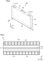
- Fig. 1 is an exploded perspective view of a battery pack 1.
- battery pack 1 includes: stacks 10 each including a plurality of battery cells 100 (see Fig. 2 ) arranged side by side in the Y axis direction (first direction); a case 20 that accommodates stacks 10; and bus bar modules 30 disposed on stacks 10.
- Stacks 10 include a stack 10A (first stack), a stack 10B (second stack), and a stack 10C (third stack).
- Stacks 10A, 10B are adjacent to each other in the X axis direction (second direction).
- Stacks 10B, 10C are adjacent to each other in the X axis direction.
- Case 20 has side walls 21 facing stacks 10A, 10B, 10C in the Y axis direction. Side walls 21 directly support stacks 10A, 10B, 10C from both sides in the Y axis direction.
- battery pack 1 employs a Cell-to-Pack structure in which stacks 10 each including the plurality of battery cells 100 are directly stored in the case.
- Bus bar modules 30 include: a bus bar module 30A (first bus bar module) disposed on stack 10A; a bus bar module 30B (second bus bar module) disposed on stack 10B; and a bus bar module 30C (third bus bar module) disposed on stack 10C.
- Fig. 2 is a perspective view showing a configuration of a battery cell 100 included in each of stacks 10A, 10B, 10C. As shown in Fig. 2 , battery cell 100 has a prismatic shape. Battery cell 100 has electrode terminals 110, a housing 120, and a gas-discharge valve 130.
- Electrode terminals 110 are formed on housing 120. Electrode terminals 110 have a positive electrode terminal 111 and a negative electrode terminal 112 as two electrode terminals 110 arranged side by side along an X axis direction (second direction) orthogonal to a Y axis direction (first direction). Positive electrode terminal 111 and negative electrode terminal 112 are provided to be separated from each other in the X axis direction.
- Housing 120 has a substantially rectangular parallelepiped shape. An electrode assembly (not shown) and an electrolyte solution (not shown) are accommodated in housing 120. Housing 120 includes an upper surface 121, a lower surface 122, a first side surface 123, a second side surface 124, and a third side surface 125.
- Upper surface 121 is a flat surface orthogonal to the Z axis direction. Electrode terminals 110 are disposed on upper surface 121. Lower surface 122 faces upper surface 121 along the Z axis direction (third direction) orthogonal to the Y axis direction (first direction) and the X axis direction (second direction).
- Each of first side surface 123 and second side surface 124 is constituted of a flat surface orthogonal to the Y axis direction.
- Each of first side surface 123 and second side surface 124 has the largest area among the areas of the plurality of side surfaces of housing 120.
- Each of first side surface 123 and second side surface 124 has a rectangular shape when viewed in the Y axis direction.
- Each of first side surface 123 and second side surface 124 has a rectangular shape in which the X axis direction corresponds to the long-side direction and the Z axis direction corresponds to the short-side direction when viewed in the Y axis direction.
- the plurality of battery cells 100 are stacked such that first side surfaces 123 of battery cells 100, 100 adjacent to each other in the Y axis direction face each other and second side surfaces 124 of battery cells 100, 100 adjacent to each other in the Y axis direction face each other.
- positive electrode terminals 111 and negative electrode terminals 112 are alternately arranged in the Y axis direction in which the plurality of battery cells 100 are stacked.
- Gas-discharge valve 130 is provided in upper surface 121. When internal pressure of housing 120 becomes more than or equal to a predetermined value due to gas generated inside housing 120, gas-discharge valve 130 is opened to discharge the gas to the outside of housing 120.
- Fig. 3 is a top view of a plate member 310 included in bus bar module 30.
- Fig. 4 is a perspective view showing a structure around a bus bar 320 in bus bar module 30.
- Each of bus bar modules 30A, 30B, 30C includes plate member 310 shown in Fig. 3 .
- plate member 310 includes: end surfaces 311 located at end portions in the Y axis direction; end surfaces 312 located at end portions in the X axis direction; through holes 313 formed at positions corresponding to gas-discharge valves 130 of battery cells 100; and wall portions 314 that partition a space on plate member 310 into a plurality of spaces.
- bus bar 320 is accommodated in each space partitioned by wall portion 314.
- Bus bar 320 is composed of a conductor (typically, a metal member).
- Bus bar 320 electrically connects electrode terminals 110 of the plurality of battery cells 100 to each other.
- Bus bar 320 includes: a root portion 321 extending in the Y axis direction; and a connection portion 322 (first connection portion) and a connection portion 323 (second connection portion) each protruding from root portion 321 in the X axis direction.
- Connection portions 322, 323 are each connected to electrode terminals 110 of two adjacent battery cells 100 in the Y axis direction.
- Wall portion 314 of plate member 310 includes a first portion 314A, a second portion 314B, and a third portion 314C.
- First portion 314A and second portion 314B are formed to extend in the X axis direction.
- First portion 314A and second portion 314B are located at positions separated from each other in the Y axis direction.
- Third portion 314C connects first portion 314A and second portion 314B.
- Ribs 315 and locks 316 are formed in wall portion 314. Ribs 315 protrude from positions adjacent to third portion 314C of wall portion 314 to both sides in the Y axis direction. Ribs 315 position the plurality of adjacent bus bars 320 in the Y axis direction. Locks 316 lock bus bars 320 in the Z axis direction.
- the shapes and arrangements of ribs 315 and locks 316 are not limited to those shown in Fig. 4 , and can be appropriately changed.
- Bus bar 320 is connected to a wiring 410.
- Wiring 410 is fixed to bus bar 320 by a screw 420.
- the implementations of wiring 410 and screw 420 are not limited to those shown in Fig. 4 , and the wiring may be constituted of, for example, a flexible wiring board.
- Electrode terminal 110 of battery cell 100 and bus bar 320 are positioned relative to each other in the X axis direction and the Y axis direction and are then welded and joined to each other. By precisely performing this positioning, the step of welding electrode terminal 110 and bus bar 320 can be performed in a highly efficient and high-quality manner.
- bus bar 320 is precisely positioned with respect to plate member 310 in the X axis direction and the Y axis direction. Therefore, plate member 310 and stack 10 are required to be positioned precisely.
- bus bar module 30 (plate member 310) according to the present embodiment will be described with reference to Figs. 5 to 8 .
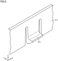
- Fig. 5 is a diagram showing the positioning mechanism of bus bar module 30 in the Y axis direction.
- plate member 310 of bus bar module 30 has a positioning mechanism 317 that positions bus bar module 30 in the Y axis direction by biasing side wall 21 of case 20.
- Positioning mechanism 317 shown in Fig. 5 is constituted of a protuberance having a snap-fit shape and formed at end surface 311 of plate member 310.
- the protuberance constituting positioning mechanism 317 protrudes from end surface 311 of plate member 310 to the side wall 21 side.
- positioning mechanism 317 presses side wall 21 of case 20 to bias plate member 310 toward a predetermined position.
- bus bar module 30 is positioned in the Y axis direction.
- Positioning mechanism 317 may be provided at each of end surfaces 311 of plate member 310 on the both sides in the Y axis direction, or may be provided only at end surface 311 of plate member 310 on one side in the Y axis direction.
- plate member 310 is biased toward the center of case 20 in the Y axis direction, and is positioned at a position at which biasing forces by positioning mechanisms 317 on the both sides are balanced.
- positioning mechanism 317 is provided on one side in the Y axis direction
- plate member 310 is biased toward side wall 21 opposite to the side on which positioning mechanism 317 is provided, and is positioned with side wall 21 serving as a reference plane.
- positioning mechanism 317 is deformed toward the central side of stack 10 as a reaction to the pressing of side wall 21 of case 20.
- positioning mechanism 317 is preferably located at a position so as not to interfere with gas-discharge valve 130 when viewed in the Z axis direction.
- bus bar module 30 can be positioned in the Y axis direction without affecting discharging of the gas from gas-discharge valve 130 of battery cell 100 located at the end portion in the Y axis direction.
- Fig. 6 is a perspective view showing a structure between bus bar module 30 and upper surface 121 of battery cell 100.
- stack 10 includes a separator 11 provided between the plurality of battery cells 100.
- Separator 11 may be a film or tape that covers first side surface 123, second side surface 124, and third side surface 125 of battery cell 100.
- Separator 11 may be a film that wraps around housing 120.
- Separator 11 may be a plate-shaped member (plate) interposed between battery cells 100 adjacent to each other. Separator 11 can be also formed by combining the film or tape with the plate-shaped member.
- Separator 11 has a protrusion 11A that protrudes to the plate member 310 side with respect to the plurality of battery cells 100. Plate member 310 is provided with a recess 318 that avoids protrusion 11A of separator 11.
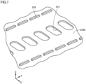
- Fig. 7 is a perspective view showing the rear surface of plate member 310.
- plate member 310 has a bottom surface 319A.
- Bottom surface 319A faces the upper surface of each battery cell 100.
- Protruding ribs 319 each protruding from bottom surface 319A of plate member 310 toward upper surface 121 of battery cell 100 are provided on portions of bottom surface 319A of plate member 310.
- Protruding ribs 319 are in abutment with upper surfaces 121 of battery cells 100.
- protruding ribs 319 are intermittently formed on both sides beside through holes 313 so as to extend in the Y axis direction.
- Fig. 8 is a diagram showing a positioning mechanism of bus bar module 30 in the X axis direction.
- bus bar module 30 has a positioning mechanism 330 inserted between two adjacent stacks (stacks 10A, 10B in the example of Fig. 8 ) to position bus bar module 30 in the X axis direction.
- bus bar module 30A has a positioning mechanism 330A
- bus bar module 30B has a positioning mechanism 330B; however, the scope of the present technology is not limited to the configuration in which all the bus bar modules 30 have positioning mechanisms 330, and only part of the plurality of bus bar modules 30 may have positioning mechanism(s) 330.
- Positioning mechanism 330A has an insertion portion 331A press-fitted between stacks 10A, 10B.
- bus bar module 30A is biased in a direction away from stack 10B.
- insertion portion 331A is brought into abutment with the side surface of stack 10A, thereby positioning bus bar module 30A in the X axis direction.
- Positioning mechanism 330B has an insertion portion 331B press-fitted between stacks 10A, 10B.
- bus bar module 30B is biased in a direction away from stack 10A.
- insertion portion 331B is brought into abutment with the side surface of stack 10B, thereby positioning bus bar module 30B in the X axis direction.
- battery pack 1 employs the Cell-to-Pack structure in which stack 10 including the plurality of battery cells 100 is directly accommodated in case 20, bus bar module 30 is installed after stack 10 is accommodated in case 20 unlike in the module structure. Therefore, a mechanism different from that in the battery pack having the module structure is required for prevention of incorrect assembling of bus bar module 30.
- Fig. 9 is a diagram for illustrating an incorrect assembling prevention mechanism of bus bar module 30.
- positioning mechanisms 330A, 330B, 330C and protrusions 340A, 340B, 340C are formed in plate members 310A, 310B, 310C of bus bar modules 30A, 30B, 30C, respectively.
- Positioning mechanisms 330A, 330B, 330C (first protrusions) and protrusions 340A, 340B, 340C (second protrusions) are provided in one piece with plate members 310A, 310B, 310C, and are formed to protrude in the X axis direction from end surfaces 312 of plate members 310, respectively.
- Protrusions 340A formed in plate member 310A include a protrusion 340A1 protruding to the plate member 310B side and a protrusion 340A2 protruding opposite to plate member 310B.
- Protrusions 340B formed in plate member 310B include a protrusion 340B1 protruding to the plate member 310C side and a protrusion 340B2 protruding to the plate member 310A side.
- Protrusion 340C formed in plate member 310C protrudes to the plate member 310B side.
- bus bar module 30C is provided with a collective terminal portion 350, and bus bar module 30C can be assembled only in the correct position and correct direction. Further, since collective terminal portion 350 and an attachment portion thereof serve as a guide, bus bar module 30A or 30B, which is incorrect in type, is prevented from being assembled to a location at which bus bar module 30C should be installed.
- protrusion 340A1 of plate member 310A interferes with protrusion 340C of plate member 310C.
- positioning mechanism 330A provided in plate member 310A interferes with positioning mechanism 330C provided in plate member 310C.
- bus bar module 30B if an attempt is made to assemble bus bar module 30B to a location at which bus bar module 30A should be installed, protrusions 340B2 of plate members 310B interfere with each other. Further, positioning mechanisms 330B provided in plate members 310B also interfere with each other.
- bus bar module 30 according to the present embodiment is thus provided with the mechanism that hinders incorrect assembling by interference and that causes no interference when correctly assembled, incorrect assembling of bus bar module 30 can be prevented also in battery pack 1 having the Cell-to-Pack structure.
- bus bar module 30 according to the present embodiment when arranging a plurality of bus bar modules having different shapes in one battery pack, there is only one manner of assembling in which the bus bar modules having different shapes do not interfere with each other.
- battery pack 1 employs the Cell-to-Pack structure, a member such as a binding bar in the module structure cannot be used as a member for positioning bus bar module 30.
- bus bar module 30 can be precisely positioned in battery pack 1 having the Cell-to-Pack structure without providing a complicated mechanism.
- protruding ribs 319 protruding from bottom surface 319A of plate member 310 toward battery cells 100 are in abutment with upper surfaces 121 of battery cells 100.
- protruding ribs 319 protruding from bottom surface 319A of plate member 310 toward battery cells 100 are in abutment with upper surfaces 121 of battery cells 100.
- protruding ribs 319 are not limited to those shown in Fig. 7 . Further, in the present technology, each protruding rib 319 is not necessarily an essential configuration.
- plate member 310 is provided with recess 318 that avoids protrusion 11A of separator 11, movement of plate member 310 in the Y axis direction is not hindered by protrusion 11A of separator 11 when positioning plate member 310 in the Y axis direction using positioning mechanism 317. Therefore, plate member 310 can be positioned smoothly and precisely.
- protrusion 11A of separator 11 and recess 318 of plate member 310 are not necessarily essential configurations.
- Battery pack 1 is provided with positioning mechanism 330 that is inserted between stacks 10A, 10B and that positions bus bar modules 30A, 30B in the X axis direction. Therefore, plate member 310 can be positioned in the X axis direction as well as the Y axis direction.
- positioning mechanism 330 for the positioning in the X axis direction is not necessarily an essential configuration. Further, all of the plurality of bus bar modules 30A, 30B, 30C may include positioning mechanisms 330, or part of the plurality of bus bar modules 30A, 30B, 30C may include positioning mechanism(s) 330.
- the bus bar module is provided with the protrusion that hinders incorrect assembling by interference and that causes no interference when correctly assembled, incorrect assembling of the bus bar module can be prevented also in the battery pack having the Cell-to-Pack structure.
Landscapes
- Chemical & Material Sciences (AREA)
- Chemical Kinetics & Catalysis (AREA)
- Electrochemistry (AREA)
- General Chemical & Material Sciences (AREA)
- Engineering & Computer Science (AREA)
- Manufacturing & Machinery (AREA)
- Life Sciences & Earth Sciences (AREA)
- Sustainable Development (AREA)
- Sustainable Energy (AREA)
- Power Engineering (AREA)
- Transportation (AREA)
- Mechanical Engineering (AREA)
- Aviation & Aerospace Engineering (AREA)
- Connection Of Batteries Or Terminals (AREA)
- Battery Mounting, Suspending (AREA)
Applications Claiming Priority (1)
| Application Number | Priority Date | Filing Date | Title |
|---|---|---|---|
| JP2023110146A JP7769664B2 (ja) | 2023-07-04 | 2023-07-04 | 電池パック |
Publications (1)
| Publication Number | Publication Date |
|---|---|
| EP4489196A1 true EP4489196A1 (de) | 2025-01-08 |
Family
ID=91193547
Family Applications (1)
| Application Number | Title | Priority Date | Filing Date |
|---|---|---|---|
| EP24177125.2A Pending EP4489196A1 (de) | 2023-07-04 | 2024-05-21 | Batteriepack |
Country Status (5)
| Country | Link |
|---|---|
| US (1) | US20250015446A1 (de) |
| EP (1) | EP4489196A1 (de) |
| JP (1) | JP7769664B2 (de) |
| KR (1) | KR20250006719A (de) |
| CN (1) | CN119275481A (de) |
Citations (4)
| Publication number | Priority date | Publication date | Assignee | Title |
|---|---|---|---|---|
| JP5521639B2 (ja) * | 2010-02-25 | 2014-06-18 | 株式会社オートネットワーク技術研究所 | 電池接続アセンブリ |
| KR101795718B1 (ko) * | 2015-10-08 | 2017-11-10 | 주식회사 피플웍스 | 확장형 배터리 셀 모듈 조립체 |
| CN217468616U (zh) | 2022-06-16 | 2022-09-20 | 华鼎国联四川电池材料有限公司 | 集成式无模组电池包 |
| US20230187759A1 (en) * | 2021-12-13 | 2023-06-15 | Hyundai Motor Company | Battery pack for vehicle |
Family Cites Families (6)
| Publication number | Priority date | Publication date | Assignee | Title |
|---|---|---|---|---|
| JP3681051B2 (ja) * | 1999-12-28 | 2005-08-10 | 本田技研工業株式会社 | 蓄電素子装置 |
| JP2013097894A (ja) * | 2011-10-28 | 2013-05-20 | Auto Network Gijutsu Kenkyusho:Kk | 電池用配線モジュール |
| US9966584B2 (en) * | 2013-03-11 | 2018-05-08 | Atieva, Inc. | Bus bar for battery packs |
| JP2017004926A (ja) * | 2015-06-15 | 2017-01-05 | 株式会社オートネットワーク技術研究所 | 蓄電モジュール、及び車載蓄電モジュール |
| KR102727483B1 (ko) * | 2019-10-10 | 2024-11-06 | 주식회사 엘지에너지솔루션 | 쇼트 방지 및 충격 보호 구조가 강화된 배터리 팩 |
| JP7385629B2 (ja) * | 2021-07-06 | 2023-11-22 | プライムプラネットエナジー&ソリューションズ株式会社 | 蓄電モジュールおよび蓄電パック |
-
2023
- 2023-07-04 JP JP2023110146A patent/JP7769664B2/ja active Active
-
2024
- 2024-05-21 EP EP24177125.2A patent/EP4489196A1/de active Pending
- 2024-06-27 KR KR1020240084383A patent/KR20250006719A/ko active Pending
- 2024-07-01 US US18/760,761 patent/US20250015446A1/en active Pending
- 2024-07-02 CN CN202410876543.3A patent/CN119275481A/zh active Pending
Patent Citations (4)
| Publication number | Priority date | Publication date | Assignee | Title |
|---|---|---|---|---|
| JP5521639B2 (ja) * | 2010-02-25 | 2014-06-18 | 株式会社オートネットワーク技術研究所 | 電池接続アセンブリ |
| KR101795718B1 (ko) * | 2015-10-08 | 2017-11-10 | 주식회사 피플웍스 | 확장형 배터리 셀 모듈 조립체 |
| US20230187759A1 (en) * | 2021-12-13 | 2023-06-15 | Hyundai Motor Company | Battery pack for vehicle |
| CN217468616U (zh) | 2022-06-16 | 2022-09-20 | 华鼎国联四川电池材料有限公司 | 集成式无模组电池包 |
Also Published As
| Publication number | Publication date |
|---|---|
| KR20250006719A (ko) | 2025-01-13 |
| CN119275481A (zh) | 2025-01-07 |
| JP2025008194A (ja) | 2025-01-20 |
| JP7769664B2 (ja) | 2025-11-13 |
| US20250015446A1 (en) | 2025-01-09 |
Similar Documents
| Publication | Publication Date | Title |
|---|---|---|
| EP4489196A1 (de) | Batteriepack | |
| EP4489197B1 (de) | Batteriepack | |
| EP4333157A1 (de) | Batteriemodul | |
| EP4489195A1 (de) | Batteriepack | |
| EP4489194A2 (de) | Batteriepack | |
| EP4517962A1 (de) | Batteriepack | |
| EP4304307A1 (de) | Gehäuse für elektronische steuervorrichtung | |
| US20250079606A1 (en) | Battery pack | |
| EP4704231A1 (de) | Batterieanordnung und batteriepack | |
| EP4358252A1 (de) | Batteriemodul | |
| US20250070397A1 (en) | Battery pack and bus bar | |
| EP4358266A1 (de) | Batteriemodul | |
| EP4358251B1 (de) | Batteriemodul | |
| US20240234917A9 (en) | Battery module | |
| EP4358250A1 (de) | Batteriemodul | |
| EP4358268A1 (de) | Batteriemodul | |
| EP4358247A1 (de) | Batteriemodul |
Legal Events
| Date | Code | Title | Description |
|---|---|---|---|
| PUAI | Public reference made under article 153(3) epc to a published international application that has entered the european phase |
Free format text: ORIGINAL CODE: 0009012 |
|
| STAA | Information on the status of an ep patent application or granted ep patent |
Free format text: STATUS: REQUEST FOR EXAMINATION WAS MADE |
|
| 17P | Request for examination filed |
Effective date: 20240521 |
|
| AK | Designated contracting states |
Kind code of ref document: A1 Designated state(s): AL AT BE BG CH CY CZ DE DK EE ES FI FR GB GR HR HU IE IS IT LI LT LU LV MC ME MK MT NL NO PL PT RO RS SE SI SK SM TR |