EP4489177A1 - Pouch cell venting detection device - Google Patents
Pouch cell venting detection device Download PDFInfo
- Publication number
- EP4489177A1 EP4489177A1 EP23760268.5A EP23760268A EP4489177A1 EP 4489177 A1 EP4489177 A1 EP 4489177A1 EP 23760268 A EP23760268 A EP 23760268A EP 4489177 A1 EP4489177 A1 EP 4489177A1
- Authority
- EP
- European Patent Office
- Prior art keywords
- support
- rotary part
- pouch
- venting
- cell
- Prior art date
- Legal status (The legal status is an assumption and is not a legal conclusion. Google has not performed a legal analysis and makes no representation as to the accuracy of the status listed.)
- Pending
Links
Images



Classifications
-
- H—ELECTRICITY
- H01—ELECTRIC ELEMENTS
- H01M—PROCESSES OR MEANS, e.g. BATTERIES, FOR THE DIRECT CONVERSION OF CHEMICAL ENERGY INTO ELECTRICAL ENERGY
- H01M50/00—Constructional details or processes of manufacture of the non-active parts of electrochemical cells other than fuel cells, e.g. hybrid cells
- H01M50/10—Primary casings; Jackets or wrappings
- H01M50/102—Primary casings; Jackets or wrappings characterised by their shape or physical structure
- H01M50/105—Pouches or flexible bags
-
- H—ELECTRICITY
- H01—ELECTRIC ELEMENTS
- H01M—PROCESSES OR MEANS, e.g. BATTERIES, FOR THE DIRECT CONVERSION OF CHEMICAL ENERGY INTO ELECTRICAL ENERGY
- H01M10/00—Secondary cells; Manufacture thereof
- H01M10/42—Methods or arrangements for servicing or maintenance of secondary cells or secondary half-cells
- H01M10/4285—Testing apparatus
-
- G—PHYSICS
- G01—MEASURING; TESTING
- G01B—MEASURING LENGTH, THICKNESS OR SIMILAR LINEAR DIMENSIONS; MEASURING ANGLES; MEASURING AREAS; MEASURING IRREGULARITIES OF SURFACES OR CONTOURS
- G01B5/00—Measuring arrangements characterised by the use of mechanical techniques
- G01B5/30—Measuring arrangements characterised by the use of mechanical techniques for measuring the deformation in a solid, e.g. mechanical strain gauge
-
- G—PHYSICS
- G01—MEASURING; TESTING
- G01M—TESTING STATIC OR DYNAMIC BALANCE OF MACHINES OR STRUCTURES; TESTING OF STRUCTURES OR APPARATUS, NOT OTHERWISE PROVIDED FOR
- G01M3/00—Investigating fluid-tightness of structures
- G01M3/02—Investigating fluid-tightness of structures by using fluid or vacuum
- G01M3/26—Investigating fluid-tightness of structures by using fluid or vacuum by measuring rate of loss or gain of fluid, e.g. by pressure-responsive devices, by flow detectors
-
- H—ELECTRICITY
- H01—ELECTRIC ELEMENTS
- H01M—PROCESSES OR MEANS, e.g. BATTERIES, FOR THE DIRECT CONVERSION OF CHEMICAL ENERGY INTO ELECTRICAL ENERGY
- H01M10/00—Secondary cells; Manufacture thereof
- H01M10/42—Methods or arrangements for servicing or maintenance of secondary cells or secondary half-cells
-
- H—ELECTRICITY
- H01—ELECTRIC ELEMENTS
- H01M—PROCESSES OR MEANS, e.g. BATTERIES, FOR THE DIRECT CONVERSION OF CHEMICAL ENERGY INTO ELECTRICAL ENERGY
- H01M10/00—Secondary cells; Manufacture thereof
- H01M10/42—Methods or arrangements for servicing or maintenance of secondary cells or secondary half-cells
- H01M10/48—Accumulators combined with arrangements for measuring, testing or indicating the condition of cells, e.g. the level or density of the electrolyte
-
- H—ELECTRICITY
- H01—ELECTRIC ELEMENTS
- H01M—PROCESSES OR MEANS, e.g. BATTERIES, FOR THE DIRECT CONVERSION OF CHEMICAL ENERGY INTO ELECTRICAL ENERGY
- H01M50/00—Constructional details or processes of manufacture of the non-active parts of electrochemical cells other than fuel cells, e.g. hybrid cells
- H01M50/10—Primary casings; Jackets or wrappings
- H01M50/172—Arrangements of electric connectors penetrating the casing
- H01M50/174—Arrangements of electric connectors penetrating the casing adapted for the shape of the cells
- H01M50/178—Arrangements of electric connectors penetrating the casing adapted for the shape of the cells for pouch or flexible bag cells
-
- H—ELECTRICITY
- H01—ELECTRIC ELEMENTS
- H01M—PROCESSES OR MEANS, e.g. BATTERIES, FOR THE DIRECT CONVERSION OF CHEMICAL ENERGY INTO ELECTRICAL ENERGY
- H01M50/00—Constructional details or processes of manufacture of the non-active parts of electrochemical cells other than fuel cells, e.g. hybrid cells
- H01M50/50—Current conducting connections for cells or batteries
- H01M50/572—Means for preventing undesired use or discharge
- H01M50/574—Devices or arrangements for the interruption of current
- H01M50/578—Devices or arrangements for the interruption of current in response to pressure
-
- H—ELECTRICITY
- H01—ELECTRIC ELEMENTS
- H01M—PROCESSES OR MEANS, e.g. BATTERIES, FOR THE DIRECT CONVERSION OF CHEMICAL ENERGY INTO ELECTRICAL ENERGY
- H01M2200/00—Safety devices for primary or secondary batteries
- H01M2200/20—Pressure-sensitive devices
-
- Y—GENERAL TAGGING OF NEW TECHNOLOGICAL DEVELOPMENTS; GENERAL TAGGING OF CROSS-SECTIONAL TECHNOLOGIES SPANNING OVER SEVERAL SECTIONS OF THE IPC; TECHNICAL SUBJECTS COVERED BY FORMER USPC CROSS-REFERENCE ART COLLECTIONS [XRACs] AND DIGESTS
- Y02—TECHNOLOGIES OR APPLICATIONS FOR MITIGATION OR ADAPTATION AGAINST CLIMATE CHANGE
- Y02E—REDUCTION OF GREENHOUSE GAS [GHG] EMISSIONS, RELATED TO ENERGY GENERATION, TRANSMISSION OR DISTRIBUTION
- Y02E60/00—Enabling technologies; Technologies with a potential or indirect contribution to GHG emissions mitigation
- Y02E60/10—Energy storage using batteries
Definitions
- the present invention relates to a device for detecting venting of a pouch cell, and more particularly, to a device for detecting venting of a pouch cell, which is capable of mechanically detecting the venting of the pouch cell using a change in volume of the pouch cell and immediately cutting off a voltage when the venting occurs.
- Secondary batteries refer to batteries that are chargeable and dischargeable unlike non-rechargeable primary batteries, and types of the secondary batteries include a nickel-cadmium battery, a nickel-hydrogen battery, a lithium-ion battery, a lithium-ion polymer battery, and so on.
- Such secondary batteries are applied to and used in not only small-sized products such as digital camera, notebook computer, mobile phone, PDA and e-bike, but also large-sized products, such as electric vehicle and hybrid vehicle, which require higher powers, energy storage systems for storing surplus electricity or new renewable energy, and energy storage systems for backup.
- These secondary batteries are classified into a pouch type secondary battery, a can type secondary battery, and so on, according to the material of a battery case that accommodates an electrode assembly.
- a pouch type an electrode assembly is accommodated in a pouch made of a flexible polymer material having a variable shape.
- the can type an electrode assembly is accommodated in a case made of a material such as metal or plastic, which has a fixed shape.
- the battery case has the electrode assembly accommodated therein as above and is injected with an electrolyte, and then is sealed so as to operate as a battery.
- gas is generated, and particularly when overcharge of the batteries, an internal short circuit or the like occurs, the gas is excessively generated in the battery case to cause an increase in pressure inside the battery case, and this leads to performance degradation of the batteries.
- a test process or device that performs a venting operation in which inner gas is discharged to the outside is essential for the secondary batteries.
- an occurrence of unexpected venting during an advance safety review and test of a pouch cell may not only cause contaminant of a surrounding test area, but also lead to a risk of accidents caused by, for example, electrolyte leakage and dielectric breakdown, through a venting portion.
- outside air flows into the secondary batteries adversely during the venting of the secondary batteries and in this case, not only the performance of the batteries is degraded, but also reaction of oxygen in the batteries leads ignition or explosion of the batteries to seriously threaten user's safety.
- a device is necessary which is capable of immediately measuring the venting and cutting off a voltage during the test of the pouch cell.
- the present invention has been devised to solve the problems as above and an object of the present invention is to provide a device for detecting venting of a pouch cell, which is capable of mechanically detecting the venting of the pouch cell using a change in volume of the pouch cell and immediately cutting off a voltage when the venting occurs.
- a device for detecting venting of a pouch cell is a device for detecting venting of a pouch cell that includes a pouch case and an electrode lead protruding to one side of the pouch case.
- the device includes a body part, a rotating means provided on one surface of the body part, a rotary part rotatably coupled to the one surface of the body part by the rotating means and having one side provided with a connection surface that is in contact with the electrode lead, a support provided to face the pouch case at the other side of the rotary part, and a cell pressing block coupled to an end of the support and having a pressing surface that presses an outer surface of the pouch case.
- the cell pressing block may transmit pressing force due to an increase in volume of the pouch case to the rotary part through the support, and the rotary part may rotate in a first direction by the pressing force transmitted through the support, wherein connection with the electrode lead may be maintained on the connection surface.
- the rotating means may include a first shaft member, which protrudes from the one surface of the body part, and a first torsion spring that couples the first shaft member and the rotary part to each other and supplies torque to the rotary part.
- the first torsion spring may transmit torque generated as the rotary part rotates in the first direction to the rotary part, and the rotary part may rotate in a second direction by the torque so that the connection with the electrode lead is released on the connection surface.
- the rotary part may be provided as a conductor.
- the rotary part may be provided with a connection terminal connected to an external device at the other side based on the rotating means.
- connection surface may be provided as a curved surface that is convex outward.
- connection surface may be provided to have a radius of curvature that gradually decreases toward a side at which the pouch case is disposed.
- the support may be hinge-coupled at the other side of the rotary part.
- the cell pressing block may be provided as an insulator.
- the pressing surface may be provided as a curved surface that is convex outward.
- the device for detecting the venting of the pouch cell may further include a support means that is provided on the one surface of the body part and presses and supports the rotary part on an end of the rotary part in a first direction.
- the support means may include a second shaft member that protrudes from the one surface of the body part, a torsion arm that supports the rotary part, and a second torsion spring that couples the second shaft member and the torsion arm to each other and supplies torque to the torsion arm.
- a support may include a first support, in which a hollow having one side opened is defined, a second support having one side, at which an end is coupled to the cell pressing block, and the other side, at which an end is inserted into the hollow of the first support, and a compression spring inserted into the hollow of the first support, wherein the compression spring is provided between the other side of the first support, which is closed, and the second support to supply elastic force to the second support.
- the device for detecting the venting of the pouch cell is the device for detecting the venting of the pouch cell that includes the pouch case and the electrode lead protruding to the one side of the pouch case.
- the device may include the body part, the rotating means provided on the one surface of the body part, the rotary part rotatably coupled to the one surface of the body part by the rotating means and having the one side provided with the connection surface that is in contact with the electrode lead, the support provided to face the pouch case at the other side of the rotary part, and the cell pressing block coupled to the end of the support and having the pressing surface that presses the outer surface of the pouch case. Accordingly, the venting of the pouch cell may be mechanically detected using the change in the volume of the pouch cell and the voltage may be immediately cut off when the venting occurs.
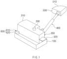
- FIG. 1 is a perspective view illustrating a device for detecting venting of a pouch cell according to Embodiment 1 of the present invention.
- FIG. 2 is a side view illustrating a state in which the device for detecting the venting of the pouch cell is mounted on the pouch cell according to Embodiment 1 of the present invention.
- the device for detecting the venting of the pouch cell is a device for detecting venting of a pouch cell 10 that includes a pouch case 11 and an electrode lead 12 protruding to one side of the pouch case 11.
- the device includes a body part 100, a rotating means 200, a rotary part 300, a support 400, and a cell pressing block 500.
- the rotating means 200 is provide on one surface of the body part 100, and the rotary part 300 is rotatably coupled to the one surface of the body part 100 by the rotating means 200 and has one side provided with a connection surface 310 in contact with the electrode lead 12.
- the support 400 is provided to face the pouch case 11 at the other side of the rotary part 300, and the cell pressing block 500 is coupled to an end of the support 400 and has a pressing surface 510 that presses an outer surface of the pouch case 11.
- the cell pressing block 500 presses the outer surface of the pouch case 11 as above, movement of each of the cell pressing block 500 and the support 400 occurs according to a change in volume of the pouch cell 10, and it causes rotation of the rotary part 300 coupled to the support 400. Consequently, the change in volume of the cell may be used to mechanically detect the venting of the pouch cell 10, and when the venting occurs, connection of the rotary part 300 and the electrode lead 12 may be released to immediately cut off a voltage.
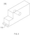
- FIG. 3 is a perspective view illustrating a body part of the device for detecting the venting of the pouch cell according to Embodiment 1 of the present invention.
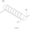
- FIG. 4 is a perspective view illustrating a rotating means of the device for detecting the venting of the pouch cell according to Embodiment 1 of the present invention.
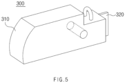
- FIG. 5 is a perspective view illustrating a rotary part of the device for detecting the venting of the pouch cell according to Embodiment 1 of the present invention.
- FIG. 6 is an enlarged side view illustrating a cell pressing block and a support of the device for detecting the venting of the pouch cell according to Embodiment 1 of the present invention.
- FIG. 7 is a side view illustrating an operation of the device for detecting the venting of the pouch cell according to Embodiment 1 of the present invention before the venting of the pouch cell occurs.
- FIG. 8 is a side view illustrating an operation of the device for detecting the venting of the pouch cell according to Embodiment 1 of the present invention after the venting of the pouch cell occurs.
- FIG. 9 is a side view illustrating a device for detecting venting of a pouch cell according to Embodiment 2 of the present invention.
- the body part 100 which is a component serving as a center of the device for detecting the venting of the pouch cell, may be a component to which each of the rotating means 200 and the rotary part 300 is coupled, and also may be a component to be mounted in a cycle chamber, a high-temperature storage chamber, or a die in a test process in which the device for detecting the venting of the pouch cell according to the present invention is used.
- the device for detecting the venting of the pouch cell according to the present invention is not necessarily used in the test process, and may be mounted in a secondary battery module and detect the venting of the pouch cell 10 during the use thereof.
- the shape of the body part 100 is not particularly limited.
- the body part 100 may have a shape having at least one flat surface so that the rotary part 300 is easily rotatable in a coupled state, and may be provided in a shape in which a coupling hole to which the rotating means 200 is coupled passes through the one surface or the one surface and the other surface.
- the body part 100 may have one side that includes a lead seating part 110 having a stepped shape so that the electrode lead 12 is seated thereon. Accordingly, connection with the rotary part 300 may be easily maintained or released in a state in which the electrode lead 12 is stably seated on the one side of the body part 100.
- step height of the lead seating part 110 Preferably, however, the step height and width may be provided to be the same as a height and width of the electrode lead 12 or greater than the height and width of the electrode lead 12 for the electrode lead 12 to be stably seated.
- the rotating means 200 which is provided on the one surface of the body part 100, may be a component that fixes the rotary part 300 to the body part 100, and also may be a component that rotates the rotary part 30 in a first direction or in a second direction opposite to the first direction.
- the first direction may mean a clockwise direction in FIG. 2
- the second direction may mean a counterclockwise direction in FIG. 2 .
- the rotating means 200 may include a first shaft member 210 and a first torsion spring 220.
- the first shaft member 210 may be coupled to protrude from the one surface of the body part 100, and the first torsion spring 220 may couple the first shaft member 210 and the rotary part 300 to each other and supply torque to the rotary part 300.
- the torque may be force generated by elastic force of the first torsion spring 220.
- torque may be generated by torsion and the rotary part 300 may rotate by the torque. An operation of the rotary part 300 by the rotating means 200 will be described in more detail below.
- the first torsion spring 220 may be provided to have a shape surrounding an outer circumference of the first shaft member 210, but is not necessarily limited thereto.
- the first torsion spring 220 may have a configuration in which the first shaft member 210 is provided as a hollow and the first torsion spring is inserted into the hollow.
- the rotary part 300 is a component, which is rotatably coupled to the one surface of the body part 100 by the rotating means 200, and is a component that is connected to the electrode lead 12 or released from the connection so as to maintain or cut off a voltage.
- the rotary part 300 may be provided as a conductor.
- connection surface 310 that is in contact with the electrode lead 12 may be provided at one side based on a position of the rotating means 200 connected to the rotary part 300, and a connection terminal 320 connected to an external device may be provided at the other side based on the rotating means 200.
- the external device may mean a current or voltage measuring device.
- connection surface 310 may be provided as a curved surface that is convex outward.
- the rotary part 300 is a component that rotates in the first direction or the second direction, and the connection surface 310 is a surface that is connected to the electrode lead 12 in the rotary part 300.
- the connection surface 310 may be provided as a curved surface that is convex outward, in order to maintain the connection with the electrode lead 12 even when the rotary part 300 rotates at a predetermined angle.
- the connection surface 310 needs to be provided as a curved surface in order to minimize damage of the electrode lead 12.
- connection surface 310 may be provided to have a radius of curvature that gradually decreases toward a side at which the pouch case 11 is disposed. That is, the curved surface of the connection surface 310 may be provided to be asymmetric, not to have a constant radius of curvature.
- a case in which the rotary part 300 rotates in the first direction is in a state in which the pouch case 11 swells up and before venting occurs, and thus, the connection of the connection surface 310 and the electrode lead 12 needs to be maintained.
- the first direction may mean a direction in which the rotary part 300 rotates to the side at which the pouch case 11 is disposed.
- connection surface 310 When the connection surface 310 is provided so that the radius of curvature of the connection surface 310 gradually decreases toward the side, at which the pouch case 11 is disposed, and the radius of curvature gradually increases toward a side opposite to the side at which the pouch case 11 is disposed, the connection of the connection surface 310 and the electrode lead 12 may be maintained even when the rotary part 300 rotates at a predetermined angle in the first direction, and the connection of the connection surface 310 and the electrode lead 12 may be released when the rotary part 300 rotates at the same angle as the predetermined angle in the second direction.
- the support 400 may be provided to face the pouch case 11 at the other side of the rotary part 300, connect the cell pressing block 500 and the rotary part 300 to each other, and transmit the pressing force transmitted from the cell pressing block 500 to the rotary part 300 or transmit the torque generated from the rotary part 300 or the rotating means 200 to the cell pressing block 500.
- the support 400 may be hinge-coupled at the other side of the rotary part 300, and accordingly, the pressing force and the torque generated in various directions may be transmitted to the rotary part 300 or the cell pressing block 500 with minimized losses thereof.
- the support 400 may be hinge-coupled to the cell pressing block 500, and the losses of the pressing force and the torque may be minimized.
- the cell pressing block 500 is a component that presses the outer surface of the pouch case 11, and, in detail, the pressing surface 510 provided as a curved surface that is convex outward may press the outer surface of the pouch case 11. Accordingly, the cell pressing block 500 may effectively transmit the pressing force due to a change in volume of the pouch, and damage of the pouch case 11 may be minimized even when the cell pressing block 500 is in contact with the pouch case 11.
- the cell pressing block 500 is a component that transmits only the pressing force due to a change in volume of the pouch case 11, the cell pressing block 500 may be provided as an insulator.
- the cell pressing block 500 may transmit the pressing force, at which the pouch cell 10 presses the cell pressing block 500 by the increase in volume of the pouch case 11, to the rotary part 300 through the support 400 in a direction D1, and the rotary part 300 may rotate in a first direction R1 by the pressing force transmitted through the support 400.
- connection with the electrode lead 12 may be still maintained on the connection surface 310 of the rotary part 300. That is, that the pouch case 11 swells up to cause the increase in volume of the pouch cell 10 is a state before the venting of the pouch cell 10 occurs. Thus, even when the rotary part 300 rotates by the pressing force, the rotary part 300 has to exist in a state, in which the connection with the electrode lead 12 is maintained, and the voltage is not cut off.
- the volume of the pouch cell 10 is rapidly reduced, and the swollen pouch case 11 is reduced in volume. Accordingly, the pressing force transmitted to the cell pressing block 500 is also rapidly reduced, and the magnitude of the torque in the second direction generated by the rotation of the rotary part 300 in the first direction becomes greater than that of the pressing force.
- the first torsion spring 220 of the rotating means 200 may transmit the torque generated as the rotary part 300 rotates in the first direction to the rotary part 300, and as the rotary part 300 rotates in the second direction by the torque, the connection with the electrode lead 12 may be released on the connection surface 310.
- the connection with the electrode lead 12 being released means that venting occurs in the pouch cell 10, and may means that the rotary part 300 provided as a conductor is spaced apart from the electrode lead 12 so that connection is electrically released to cut off the voltage.
- the device for detecting the venting of the pouch cell according to the present invention may rotate in the first direction or second direction based on the magnitude of each of the pressing force due to the increase or decrease in volume of the pouch case 11 and the torque of the first torsion spring 220, so that the connection of the connection surface 310 of the rotary part 300 and the electrode lead 12 is maintained or released to mechanically detect the venting of the pouch and cut off the voltage.
- the device for detecting the venting of the pouch cell according to the present invention may be economical, and the likelihood of malfunction may be significantly reduced to more exactly detect the venting and automatically cut off the voltage so as to secure safety during the test of the pouch cell 10.
- the device for detecting the venting of the pouch cell may further include a support means 600 that is provided on the one surface of the body part 100 and presses and supports the rotary part 300 on an end of the rotary part 300 in the first direction.
- the support means 600 pressing the rotary part 300 in the first direction may mean that the support means 600 presses the rotary part 300 so that, in order to prevent the rotary part 300 from rotating in a direction in which the connection with the electrode lead 12 is released or in a direction that is away from the pouch case 11, the pressing is performed in a direction opposite to the foregoing direction.
- the support means 600 may prevent the connection of the connection surface 310 of the rotary part 300 and the electrode lead 12 from being released by the rotation of the rotary part 300 in the second direction so as to reduce the risk of the malfunction of the device.
- the support means 600 may include a second shaft member 610 that protrudes from the one surface of the body part 100, a torsion arm 620 that supports the rotary part 300, and a second torsion spring that couples the second shaft member 610 and the torsion arm 620 to each other and supplies torque to the torsion arm 620. Accordingly, the rotary part 300 may be prevented from rotating in the second direction before the venting occur.
- Embodiment 2 of the present invention is different from Embodiment 1 in that the support 400 according to Embodiment 1 is constituted by a first support 410 and a second support 420 and further includes a compression spring 430 provided between the first support 410 and the second support 420.
- the other components of a device for detecting venting of a pouch cell may be understood as the same as those described above in Embodiment 1 and illustrated in the drawings, and also resultant effects may be expected to be the same.
- FIG. 9 is a side view illustrating a device for detecting venting of a pouch cell according to Embodiment 2 of the present invention.
- a support 400 according to Embodiment 2 of the present invention may include the first support 410, the second support 420, and the compression spring 430.
- a hollow having one side opened may be defined in the first support 410.
- the second support 420 may have one side, at which an end is coupled to a cell pressing block 500, and the other side at which an end is inserted into the hollow of the first support 410.
- the compression spring 430 may be inserted into the hollow of the first support 410 and provided between the other side of the first support 410, which is closed, and the second support 420 to supply elastic force to the second support 420.
- a rotary part 300 rotates in the first direction by pressing force transmitted to the cell pressing block 500 and the support 400.
- the compression spring 430 may be also compressed between the first support 410 and the second support 420, and as the pressing force is reduced when the venting occurs instantaneously, torque at which the rotary part 300 rotates in the second direction is obtained by the elastic force of the compression spring 430.
- the device for detecting the venting of the pouch cell according to Embodiment 2 of the present invention may additionally obtain the torque by the linear elastic force of the compression spring 430 in addition to the torque of the first torsion spring 220, and rapidly detect venting simultaneously with an occurrence of the venting and cut off a voltage.
Landscapes
- Chemical & Material Sciences (AREA)
- Chemical Kinetics & Catalysis (AREA)
- Electrochemistry (AREA)
- General Chemical & Material Sciences (AREA)
- Engineering & Computer Science (AREA)
- Manufacturing & Machinery (AREA)
- Physics & Mathematics (AREA)
- General Physics & Mathematics (AREA)
- Sealing Battery Cases Or Jackets (AREA)
- Secondary Cells (AREA)
- Air Bags (AREA)
Abstract
Description
- The present application claims the benefit of the priority of
Korean Patent Application No. 10-2022-0026196, filed on February 28, 2022 - The present invention relates to a device for detecting venting of a pouch cell, and more particularly, to a device for detecting venting of a pouch cell, which is capable of mechanically detecting the venting of the pouch cell using a change in volume of the pouch cell and immediately cutting off a voltage when the venting occurs.
- Secondary batteries refer to batteries that are chargeable and dischargeable unlike non-rechargeable primary batteries, and types of the secondary batteries include a nickel-cadmium battery, a nickel-hydrogen battery, a lithium-ion battery, a lithium-ion polymer battery, and so on. Such secondary batteries are applied to and used in not only small-sized products such as digital camera, notebook computer, mobile phone, PDA and e-bike, but also large-sized products, such as electric vehicle and hybrid vehicle, which require higher powers, energy storage systems for storing surplus electricity or new renewable energy, and energy storage systems for backup.
- These secondary batteries are classified into a pouch type secondary battery, a can type secondary battery, and so on, according to the material of a battery case that accommodates an electrode assembly. In the pouch type, an electrode assembly is accommodated in a pouch made of a flexible polymer material having a variable shape. In the can type, an electrode assembly is accommodated in a case made of a material such as metal or plastic, which has a fixed shape.
- The battery case has the electrode assembly accommodated therein as above and is injected with an electrolyte, and then is sealed so as to operate as a battery. During a charging-discharging of the secondary batteries, gas is generated, and particularly when overcharge of the batteries, an internal short circuit or the like occurs, the gas is excessively generated in the battery case to cause an increase in pressure inside the battery case, and this leads to performance degradation of the batteries.
- Thus, a test process or device that performs a venting operation in which inner gas is discharged to the outside is essential for the secondary batteries. However, an occurrence of unexpected venting during an advance safety review and test of a pouch cell may not only cause contaminant of a surrounding test area, but also lead to a risk of accidents caused by, for example, electrolyte leakage and dielectric breakdown, through a venting portion. There is also a case in which outside air flows into the secondary batteries adversely during the venting of the secondary batteries, and in this case, not only the performance of the batteries is degraded, but also reaction of oxygen in the batteries leads ignition or explosion of the batteries to seriously threaten user's safety. Thus, a device is necessary which is capable of immediately measuring the venting and cutting off a voltage during the test of the pouch cell.
- Accordingly, in the related art, a gas sensor is used to detect the venting of the pouch cell. However, there are disadvantages that not only the gas sensor is a high-cost product and thus is not preferable economically, but also monitoring by a user is continuously required. Thus, development of a machine and device capable of automatically measuring the venting and operable even without an expensive sensor is required.
- The present invention has been devised to solve the problems as above and an object of the present invention is to provide a device for detecting venting of a pouch cell, which is capable of mechanically detecting the venting of the pouch cell using a change in volume of the pouch cell and immediately cutting off a voltage when the venting occurs.
- A device for detecting venting of a pouch cell according to
Embodiment 1 of the present invention is a device for detecting venting of a pouch cell that includes a pouch case and an electrode lead protruding to one side of the pouch case. The device includes a body part, a rotating means provided on one surface of the body part, a rotary part rotatably coupled to the one surface of the body part by the rotating means and having one side provided with a connection surface that is in contact with the electrode lead, a support provided to face the pouch case at the other side of the rotary part, and a cell pressing block coupled to an end of the support and having a pressing surface that presses an outer surface of the pouch case. - The cell pressing block may transmit pressing force due to an increase in volume of the pouch case to the rotary part through the support, and the rotary part may rotate in a first direction by the pressing force transmitted through the support, wherein connection with the electrode lead may be maintained on the connection surface.
- The rotating means may include a first shaft member, which protrudes from the one surface of the body part, and a first torsion spring that couples the first shaft member and the rotary part to each other and supplies torque to the rotary part.
- The first torsion spring may transmit torque generated as the rotary part rotates in the first direction to the rotary part, and the rotary part may rotate in a second direction by the torque so that the connection with the electrode lead is released on the connection surface.
- The body part may include a lead seating part having a stepped shape so that the electrode lead is seated thereon.
- The rotary part may be provided as a conductor.
- The rotary part may be provided with a connection terminal connected to an external device at the other side based on the rotating means.
- The connection surface may be provided as a curved surface that is convex outward.
- The connection surface may be provided to have a radius of curvature that gradually decreases toward a side at which the pouch case is disposed.
- The support may be hinge-coupled at the other side of the rotary part.
- The cell pressing block may be provided as an insulator.
- The pressing surface may be provided as a curved surface that is convex outward.
- The device for detecting the venting of the pouch cell may further include a support means that is provided on the one surface of the body part and presses and supports the rotary part on an end of the rotary part in a first direction.
- The support means may include a second shaft member that protrudes from the one surface of the body part, a torsion arm that supports the rotary part, and a second torsion spring that couples the second shaft member and the torsion arm to each other and supplies torque to the torsion arm.
- In a device for detecting venting of a pouch cell according to Embodiment 2 of the present invention, a support may include a first support, in which a hollow having one side opened is defined, a second support having one side, at which an end is coupled to the cell pressing block, and the other side, at which an end is inserted into the hollow of the first support, and a compression spring inserted into the hollow of the first support, wherein the compression spring is provided between the other side of the first support, which is closed, and the second support to supply elastic force to the second support.
- The device for detecting the venting of the pouch cell according to the present invention is the device for detecting the venting of the pouch cell that includes the pouch case and the electrode lead protruding to the one side of the pouch case. The device may include the body part, the rotating means provided on the one surface of the body part, the rotary part rotatably coupled to the one surface of the body part by the rotating means and having the one side provided with the connection surface that is in contact with the electrode lead, the support provided to face the pouch case at the other side of the rotary part, and the cell pressing block coupled to the end of the support and having the pressing surface that presses the outer surface of the pouch case. Accordingly, the venting of the pouch cell may be mechanically detected using the change in the volume of the pouch cell and the voltage may be immediately cut off when the venting occurs.
-
-
FIG. 1 is a perspective view illustrating a device for detecting venting of a pouch cell according toEmbodiment 1 of the present invention. -
FIG. 2 is a side view illustrating a state in which the device for detecting the venting of the pouch cell is mounted on the pouch cell according toEmbodiment 1 of the present invention. -
FIG. 3 is a perspective view illustrating a body part of the device for detecting the venting of the pouch cell according toEmbodiment 1 of the present invention. -
FIG. 4 is a perspective view illustrating a rotating means of the device for detecting the venting of the pouch cell according toEmbodiment 1 of the present invention. -
FIG. 5 is a perspective view illustrating a rotary part of the device for detecting the venting of the pouch cell according toEmbodiment 1 of the present invention. -
FIG. 6 is an enlarged side view illustrating a cell pressing block and a support of the device for detecting the venting of the pouch cell according toEmbodiment 1 of the present invention. -
FIG. 7 is a side view illustrating an operation of the device for detecting the venting of the pouch cell according toEmbodiment 1 of the present invention before the venting of the pouch cell occurs. -
FIG. 8 is a side view illustrating an operation of the device for detecting the venting of the pouch cell according toEmbodiment 1 of the present invention after the venting of the pouch cell occurs. -
FIG. 9 is a side view illustrating a device for detecting venting of a pouch cell according to Embodiment 2 of the present invention. - Hereinafter, preferred embodiments of the present invention will be described in detail with reference to the accompanying drawings to enable those skilled in the art to which the present invention pertains to easily carry out the present invention. The present invention may, however, be embodied in different forms and should not be construed as limited by the embodiments set forth herein.
- The parts unrelated to the description, or the detailed descriptions of related well-known art that may unnecessarily obscure subject matters of the present invention, will be ruled out in order to clearly describe the present invention. Like reference numerals refer to like elements throughout the whole specification.
- Moreover, terms or words used in this specification and claims should not be restrictively interpreted as ordinary meanings or dictionary-based meanings, but should be interpreted as meanings and concepts conforming to the scope of the present invention on the basis of the principle that an inventor can properly define the concept of a term to describe and explain his or her invention in the best ways.
-
FIG. 1 is a perspective view illustrating a device for detecting venting of a pouch cell according toEmbodiment 1 of the present invention.FIG. 2 is a side view illustrating a state in which the device for detecting the venting of the pouch cell is mounted on the pouch cell according toEmbodiment 1 of the present invention. - Referring to
FIGS. 1 and2 , the device for detecting the venting of the pouch cell according to the present invention is a device for detecting venting of apouch cell 10 that includes apouch case 11 and anelectrode lead 12 protruding to one side of thepouch case 11. The device includes abody part 100, a rotating means 200, arotary part 300, asupport 400, and acell pressing block 500. - The rotating
means 200 is provide on one surface of thebody part 100, and therotary part 300 is rotatably coupled to the one surface of thebody part 100 by the rotatingmeans 200 and has one side provided with aconnection surface 310 in contact with theelectrode lead 12. Thesupport 400 is provided to face thepouch case 11 at the other side of therotary part 300, and thecell pressing block 500 is coupled to an end of thesupport 400 and has apressing surface 510 that presses an outer surface of thepouch case 11. - In the present invention, as the
cell pressing block 500 presses the outer surface of thepouch case 11 as above, movement of each of thecell pressing block 500 and thesupport 400 occurs according to a change in volume of thepouch cell 10, and it causes rotation of therotary part 300 coupled to thesupport 400. Consequently, the change in volume of the cell may be used to mechanically detect the venting of thepouch cell 10, and when the venting occurs, connection of therotary part 300 and theelectrode lead 12 may be released to immediately cut off a voltage. - Hereinafter, each of components of the device for detecting the venting of the pouch cell will be descried in detail with reference to
FIGS. 2 to 6 . -
FIG. 3 is a perspective view illustrating a body part of the device for detecting the venting of the pouch cell according toEmbodiment 1 of the present invention.FIG. 4 is a perspective view illustrating a rotating means of the device for detecting the venting of the pouch cell according toEmbodiment 1 of the present invention.FIG. 5 is a perspective view illustrating a rotary part of the device for detecting the venting of the pouch cell according toEmbodiment 1 of the present invention.FIG. 6 is an enlarged side view illustrating a cell pressing block and a support of the device for detecting the venting of the pouch cell according toEmbodiment 1 of the present invention.FIG. 7 is a side view illustrating an operation of the device for detecting the venting of the pouch cell according toEmbodiment 1 of the present invention before the venting of the pouch cell occurs.FIG. 8 is a side view illustrating an operation of the device for detecting the venting of the pouch cell according toEmbodiment 1 of the present invention after the venting of the pouch cell occurs.FIG. 9 is a side view illustrating a device for detecting venting of a pouch cell according to Embodiment 2 of the present invention. - First, referring to
FIGS. 2 and3 , thebody part 100, which is a component serving as a center of the device for detecting the venting of the pouch cell, may be a component to which each of therotating means 200 and therotary part 300 is coupled, and also may be a component to be mounted in a cycle chamber, a high-temperature storage chamber, or a die in a test process in which the device for detecting the venting of the pouch cell according to the present invention is used. However, the device for detecting the venting of the pouch cell according to the present invention is not necessarily used in the test process, and may be mounted in a secondary battery module and detect the venting of thepouch cell 10 during the use thereof. - The shape of the
body part 100 is not particularly limited. However, thebody part 100 may have a shape having at least one flat surface so that therotary part 300 is easily rotatable in a coupled state, and may be provided in a shape in which a coupling hole to which therotating means 200 is coupled passes through the one surface or the one surface and the other surface. - The
body part 100 may have one side that includes alead seating part 110 having a stepped shape so that theelectrode lead 12 is seated thereon. Accordingly, connection with therotary part 300 may be easily maintained or released in a state in which theelectrode lead 12 is stably seated on the one side of thebody part 100. There is no limitation in step height of thelead seating part 110. Preferably, however, the step height and width may be provided to be the same as a height and width of theelectrode lead 12 or greater than the height and width of theelectrode lead 12 for theelectrode lead 12 to be stably seated. - Next, a structure of each of the
rotating means 200, therotary part 300, thesupport 400, and thecell pressing block 500, and an operation of the device for detecting the venting of thepouch cell 10 according to an operation of each of the components will be reviewed. - Referring to
FIGS. 2 and4 , the rotating means 200, which is provided on the one surface of thebody part 100, may be a component that fixes therotary part 300 to thebody part 100, and also may be a component that rotates the rotary part 30 in a first direction or in a second direction opposite to the first direction. Here, the first direction may mean a clockwise direction inFIG. 2 , and the second direction may mean a counterclockwise direction inFIG. 2 . The rotating means 200 may include afirst shaft member 210 and afirst torsion spring 220. Thefirst shaft member 210 may be coupled to protrude from the one surface of thebody part 100, and thefirst torsion spring 220 may couple thefirst shaft member 210 and therotary part 300 to each other and supply torque to therotary part 300. Here, the torque may be force generated by elastic force of thefirst torsion spring 220. In thefirst torsion spring 220 of therotating means 200, when therotary part 300 rotates by pressing force transmitted by thecell pressing block 500 and thesupport 400, torque may be generated by torsion and therotary part 300 may rotate by the torque. An operation of therotary part 300 by the rotating means 200 will be described in more detail below. - The
first torsion spring 220 may be provided to have a shape surrounding an outer circumference of thefirst shaft member 210, but is not necessarily limited thereto. For example, thefirst torsion spring 220 may have a configuration in which thefirst shaft member 210 is provided as a hollow and the first torsion spring is inserted into the hollow. - Next, as illustrated in
FIGS. 2 and5 , therotary part 300 is a component, which is rotatably coupled to the one surface of thebody part 100 by the rotating means 200, and is a component that is connected to theelectrode lead 12 or released from the connection so as to maintain or cut off a voltage. To this end, therotary part 300 may be provided as a conductor. - In the
rotary part 300, theconnection surface 310 that is in contact with theelectrode lead 12 may be provided at one side based on a position of the rotating means 200 connected to therotary part 300, and aconnection terminal 320 connected to an external device may be provided at the other side based on therotating means 200. Here, the external device may mean a current or voltage measuring device. When the connection of therotary part 300 and theelectrode lead 12 is released on theconnection surface 310 by the rotation, the voltage may be cut off, and the external device connected to theconnection terminal 320 may detect whether the venting occurs. - The
connection surface 310 may be provided as a curved surface that is convex outward. Therotary part 300 is a component that rotates in the first direction or the second direction, and theconnection surface 310 is a surface that is connected to theelectrode lead 12 in therotary part 300. Thus, theconnection surface 310 may be provided as a curved surface that is convex outward, in order to maintain the connection with theelectrode lead 12 even when therotary part 300 rotates at a predetermined angle. In addition, theconnection surface 310 needs to be provided as a curved surface in order to minimize damage of theelectrode lead 12. - In addition, the
connection surface 310 may be provided to have a radius of curvature that gradually decreases toward a side at which thepouch case 11 is disposed. That is, the curved surface of theconnection surface 310 may be provided to be asymmetric, not to have a constant radius of curvature. A case in which therotary part 300 rotates in the first direction is in a state in which thepouch case 11 swells up and before venting occurs, and thus, the connection of theconnection surface 310 and theelectrode lead 12 needs to be maintained. Here, the first direction may mean a direction in which therotary part 300 rotates to the side at which thepouch case 11 is disposed. When theconnection surface 310 is provided so that the radius of curvature of theconnection surface 310 gradually decreases toward the side, at which thepouch case 11 is disposed, and the radius of curvature gradually increases toward a side opposite to the side at which thepouch case 11 is disposed, the connection of theconnection surface 310 and theelectrode lead 12 may be maintained even when therotary part 300 rotates at a predetermined angle in the first direction, and the connection of theconnection surface 310 and theelectrode lead 12 may be released when therotary part 300 rotates at the same angle as the predetermined angle in the second direction. - Referring to
FIGS. 2 and6 , thesupport 400 may be provided to face thepouch case 11 at the other side of therotary part 300, connect thecell pressing block 500 and therotary part 300 to each other, and transmit the pressing force transmitted from thecell pressing block 500 to therotary part 300 or transmit the torque generated from therotary part 300 or the rotating means 200 to thecell pressing block 500. Thesupport 400 may be hinge-coupled at the other side of therotary part 300, and accordingly, the pressing force and the torque generated in various directions may be transmitted to therotary part 300 or thecell pressing block 500 with minimized losses thereof. In addition, as illustrated inFIG. 6 , thesupport 400 may be hinge-coupled to thecell pressing block 500, and the losses of the pressing force and the torque may be minimized. - Next, as illustrated in
FIG. 2 , thecell pressing block 500 is a component that presses the outer surface of thepouch case 11, and, in detail, thepressing surface 510 provided as a curved surface that is convex outward may press the outer surface of thepouch case 11. Accordingly, thecell pressing block 500 may effectively transmit the pressing force due to a change in volume of the pouch, and damage of thepouch case 11 may be minimized even when thecell pressing block 500 is in contact with thepouch case 11. - As the
cell pressing block 500 is a component that transmits only the pressing force due to a change in volume of thepouch case 11, thecell pressing block 500 may be provided as an insulator. - Hereinafter, operating of the device for detecting the venting of the pouch cell according to the present invention will be described in detail with reference to
FIGS. 7 and8 . - During a charging or discharging of the
pouch cell 10, gas is generated by a reaction between an electrode and an electrolyte inside the cell, and, in this case, thepouch case 11 swells up and the volume of thepouch cell 10 increases. Here, as thepressing surface 510 of thecell pressing block 500 presses the outer surface of thepouch case 11, thecell pressing block 500 may transmit the pressing force, at which thepouch cell 10 presses thecell pressing block 500 by the increase in volume of thepouch case 11, to therotary part 300 through thesupport 400 in a direction D1, and therotary part 300 may rotate in a first direction R1 by the pressing force transmitted through thesupport 400. Even when therotary part 300 rotates in the first direction R1, the connection with theelectrode lead 12 may be still maintained on theconnection surface 310 of therotary part 300. That is, that thepouch case 11 swells up to cause the increase in volume of thepouch cell 10 is a state before the venting of thepouch cell 10 occurs. Thus, even when therotary part 300 rotates by the pressing force, therotary part 300 has to exist in a state, in which the connection with theelectrode lead 12 is maintained, and the voltage is not cut off. Meanwhile, when therotary part 300 rotates, torque in a second direction R2 is generated by elasticity of thefirst torsion spring 220 described above, but therotary part 300 may rotate in the first direction R1 because the pressing force due to the increase in volume of thepouch case 11 is greater than the torque. - However, when the venting occurs, the volume of the
pouch cell 10 is rapidly reduced, and theswollen pouch case 11 is reduced in volume. Accordingly, the pressing force transmitted to thecell pressing block 500 is also rapidly reduced, and the magnitude of the torque in the second direction generated by the rotation of therotary part 300 in the first direction becomes greater than that of the pressing force. - Thus, the
first torsion spring 220 of therotating means 200 may transmit the torque generated as therotary part 300 rotates in the first direction to therotary part 300, and as therotary part 300 rotates in the second direction by the torque, the connection with theelectrode lead 12 may be released on theconnection surface 310. Here, the connection with theelectrode lead 12 being released means that venting occurs in thepouch cell 10, and may means that therotary part 300 provided as a conductor is spaced apart from theelectrode lead 12 so that connection is electrically released to cut off the voltage. - As above, the device for detecting the venting of the pouch cell according to the present invention may rotate in the first direction or second direction based on the magnitude of each of the pressing force due to the increase or decrease in volume of the
pouch case 11 and the torque of thefirst torsion spring 220, so that the connection of theconnection surface 310 of therotary part 300 and theelectrode lead 12 is maintained or released to mechanically detect the venting of the pouch and cut off the voltage. When compared to an expensive gas sensor or the like, the device for detecting the venting of the pouch cell according to the present invention may be economical, and the likelihood of malfunction may be significantly reduced to more exactly detect the venting and automatically cut off the voltage so as to secure safety during the test of thepouch cell 10. - Referring to
FIGS. 2 ,7 and8 , the device for detecting the venting of the pouch cell according to the present invention may further include a support means 600 that is provided on the one surface of thebody part 100 and presses and supports therotary part 300 on an end of therotary part 300 in the first direction. Here, the support means 600 pressing therotary part 300 in the first direction may mean that the support means 600 presses therotary part 300 so that, in order to prevent therotary part 300 from rotating in a direction in which the connection with theelectrode lead 12 is released or in a direction that is away from thepouch case 11, the pressing is performed in a direction opposite to the foregoing direction. That is, in a case except when the venting occurs, the support means 600 may prevent the connection of theconnection surface 310 of therotary part 300 and theelectrode lead 12 from being released by the rotation of therotary part 300 in the second direction so as to reduce the risk of the malfunction of the device. - The support means 600 may include a
second shaft member 610 that protrudes from the one surface of thebody part 100, atorsion arm 620 that supports therotary part 300, and a second torsion spring that couples thesecond shaft member 610 and thetorsion arm 620 to each other and supplies torque to thetorsion arm 620. Accordingly, therotary part 300 may be prevented from rotating in the second direction before the venting occur. - Embodiment 2 of the present invention is different from
Embodiment 1 in that thesupport 400 according toEmbodiment 1 is constituted by afirst support 410 and asecond support 420 and further includes acompression spring 430 provided between thefirst support 410 and thesecond support 420. Thus, the other components of a device for detecting venting of a pouch cell may be understood as the same as those described above inEmbodiment 1 and illustrated in the drawings, and also resultant effects may be expected to be the same. -
FIG. 9 is a side view illustrating a device for detecting venting of a pouch cell according to Embodiment 2 of the present invention. - Referring to
FIG. 9 , asupport 400 according to Embodiment 2 of the present invention may include thefirst support 410, thesecond support 420, and thecompression spring 430. A hollow having one side opened may be defined in thefirst support 410. Thesecond support 420 may have one side, at which an end is coupled to acell pressing block 500, and the other side at which an end is inserted into the hollow of thefirst support 410. Thecompression spring 430 may be inserted into the hollow of thefirst support 410 and provided between the other side of thefirst support 410, which is closed, and thesecond support 420 to supply elastic force to thesecond support 420. - When the volume of a pouch case increases, a
rotary part 300 rotates in the first direction by pressing force transmitted to thecell pressing block 500 and thesupport 400. Here, thecompression spring 430 may be also compressed between thefirst support 410 and thesecond support 420, and as the pressing force is reduced when the venting occurs instantaneously, torque at which therotary part 300 rotates in the second direction is obtained by the elastic force of thecompression spring 430. - By including the
compression spring 430 between thefirst support 410 and thesecond support 420 as above, the device for detecting the venting of the pouch cell according to Embodiment 2 of the present invention may additionally obtain the torque by the linear elastic force of thecompression spring 430 in addition to the torque of thefirst torsion spring 220, and rapidly detect venting simultaneously with an occurrence of the venting and cut off a voltage. - Although the present invention has been described with reference to the limited embodiments and drawings, the present invention is not limited thereto and may be variously implemented by those of ordinary skill in the art to which the present invention pertains, within the technical idea of the present invention and an equivalent of the appended claims.
-
- 10: Pouch cell
- 11: Pouch case
- 12: Electrode lead
- 100: Body part
- 110: Lead seating part
- 200: Rotating means
- 210: First shaft member
- 220: First torsion spring
- 300: Rotary part
- 310: Connection surface
- 320: Connection terminal
- 400: Support
- 410: First support
- 420: Second support
- 430: Compression spring
- 500: Cell pressing block
- 510: Pressing surface
- 600: Support means
- 610: Second shaft member
- 620: Torsion arm
Claims (15)
- A device for detecting venting of a pouch cell that comprises a pouch case and an electrode lead protruding to one side of the pouch case, the device comprising:a body part;a rotating means provided on one surface of the body part;a rotary part rotatably coupled to the one surface of the body part by the rotating means and having one side provided with a connection surface that is in contact with the electrode lead;a support provided to face the pouch case at the other side of the rotary part; anda cell pressing block coupled to an end of the support and having a pressing surface configured to press an outer surface of the pouch case.
- The device of claim 1, wherein the cell pressing block transmits pressing force due to an increase in volume of the pouch case to the rotary part through the support, and
the rotary part rotates in a first direction by the pressing force transmitted through the support, wherein connection with the electrode lead is maintained on the connection surface. - The device of claim 2, wherein the rotating means comprises:a first shaft member protruding from the one surface of the body part; anda first torsion spring configured to couple the first shaft member and the rotary part to each other and supply torque to the rotary part.
- The device of claim 3, wherein the first torsion spring transmits torque generated as the rotary part rotates in the first direction to the rotary part, and
the rotary part rotates in a second direction by the torque so that the connection with the electrode lead is released on the connection surface. - The device of claim 1, wherein the body part comprises a lead seating part having a stepped shape so that the electrode lead is seated thereon.
- The device of claim 1, wherein the rotary part is provided as a conductor.
- The device of claim 1, wherein the rotary part is provided with a connection terminal connected to an external device at the other side based on the rotating means.
- The device of claim 1, wherein the connection surface is provided as a curved surface that is convex outward.
- The device of claim 8, wherein the connection surface is provided to have a radius of curvature that gradually decreases toward a side at which the pouch case is disposed.
- The device of claim 1, wherein the support is hinge-coupled at the other side of the rotary part.
- The device of claim 1, wherein the cell pressing block is provided as an insulator.
- The device of claim 1, wherein the pressing surface is provided as a curved surface that is convex outward.
- The device of claim 1, further comprising a support means provided on the one surface of the body part and configured to press and support the rotary part on an end of the rotary part in a first direction.
- The device of claim 13, wherein the support means comprises:a second shaft member protruding from the one surface of the body part;a torsion arm configured to support the rotary part; anda second torsion spring configured to couple the second shaft member and the torsion arm to each other and supply torque to the torsion arm.
- The device of claim 1, wherein the support comprises:a first support in which a hollow having one side opened is defined;a second support having one side, at which an end is coupled to the cell pressing block, and the other side, at which an end is inserted into the hollow of the first support; anda compression spring inserted into the hollow of the first support, wherein the compression spring is provided between the other side of the first support, which is closed, and the second support to supply elastic force to the second support.
Applications Claiming Priority (2)
| Application Number | Priority Date | Filing Date | Title |
|---|---|---|---|
| KR1020220026196A KR102945279B1 (en) | 2022-02-28 | 2022-02-28 | Apparatus for detecting venting of pouch cell |
| PCT/KR2023/001299 WO2023163394A1 (en) | 2022-02-28 | 2023-01-27 | Pouch cell venting detection device |
Publications (2)
| Publication Number | Publication Date |
|---|---|
| EP4489177A1 true EP4489177A1 (en) | 2025-01-08 |
| EP4489177A4 EP4489177A4 (en) | 2025-07-23 |
Family
ID=87766260
Family Applications (1)
| Application Number | Title | Priority Date | Filing Date |
|---|---|---|---|
| EP23760268.5A Pending EP4489177A4 (en) | 2022-02-28 | 2023-01-27 | Device for detecting the ventilation of a pouch cell |
Country Status (6)
| Country | Link |
|---|---|
| US (1) | US20250167319A1 (en) |
| EP (1) | EP4489177A4 (en) |
| JP (1) | JP7746593B2 (en) |
| KR (1) | KR102945279B1 (en) |
| CN (1) | CN118648156A (en) |
| WO (1) | WO2023163394A1 (en) |
Family Cites Families (8)
| Publication number | Priority date | Publication date | Assignee | Title |
|---|---|---|---|---|
| JP2006185709A (en) | 2004-12-27 | 2006-07-13 | Nissan Motor Co Ltd | Secondary battery and assembled battery using the same |
| JP2007109455A (en) | 2005-10-12 | 2007-04-26 | Toyota Motor Corp | Unit battery and battery pack |
| JP2012243556A (en) | 2011-05-19 | 2012-12-10 | Hitachi Ltd | Laminated battery, method of detecting expansion of the same, and battery module |
| DE102012207999A1 (en) * | 2012-05-14 | 2013-11-14 | Robert Bosch Gmbh | Sheath foil for a galvanic cell, electrochemical storage, electrochemical storage system, flexible foil for a sheath of a galvanic cell and method for determining a state quantity of an electrochemical storage |
| US9287593B2 (en) * | 2013-03-26 | 2016-03-15 | Ec Power, Llc | Multi-terminal battery with sensor terminal |
| KR101950463B1 (en) * | 2015-10-06 | 2019-02-20 | 주식회사 엘지화학 | Battery Module Having Prove for Sensing Expansion of Battery Cell |
| KR20170050926A (en) * | 2015-11-02 | 2017-05-11 | 주식회사 엘지화학 | A secondary battery, secondary battery charging system and secondary battery production method to prevent battery cell swelling by detecting a displacement of gas venting unit |
| CN215816008U (en) * | 2021-06-09 | 2022-02-11 | 恒大新能源技术(深圳)有限公司 | Formation detection device for soft package battery |
-
2022
- 2022-02-28 KR KR1020220026196A patent/KR102945279B1/en active Active
-
2023
- 2023-01-27 EP EP23760268.5A patent/EP4489177A4/en active Pending
- 2023-01-27 CN CN202380022220.1A patent/CN118648156A/en active Pending
- 2023-01-27 JP JP2024548756A patent/JP7746593B2/en active Active
- 2023-01-27 US US18/841,575 patent/US20250167319A1/en active Pending
- 2023-01-27 WO PCT/KR2023/001299 patent/WO2023163394A1/en not_active Ceased
Also Published As
| Publication number | Publication date |
|---|---|
| KR20230128820A (en) | 2023-09-05 |
| WO2023163394A1 (en) | 2023-08-31 |
| EP4489177A4 (en) | 2025-07-23 |
| JP2025508759A (en) | 2025-04-10 |
| KR102945279B1 (en) | 2026-03-30 |
| CN118648156A (en) | 2024-09-13 |
| US20250167319A1 (en) | 2025-05-22 |
| JP7746593B2 (en) | 2025-09-30 |
Similar Documents
| Publication | Publication Date | Title |
|---|---|---|
| EP1599915B1 (en) | Lithium ion batteries | |
| US7691530B2 (en) | Cylindrical lithium secondary battery | |
| US11581600B2 (en) | Venting device | |
| KR100467698B1 (en) | Cylindrical type lithium secondary battery and the fabrication method of the same | |
| KR100846955B1 (en) | Cylindrical secondary battery | |
| KR20170050926A (en) | A secondary battery, secondary battery charging system and secondary battery production method to prevent battery cell swelling by detecting a displacement of gas venting unit | |
| EP4024558A1 (en) | Vibration test jig and vibration test apparatus for cylindrical battery cell | |
| KR20090026418A (en) | Secondary battery | |
| US20060093895A1 (en) | Rechargeable battery | |
| KR100662174B1 (en) | Nonaqueous Electrolyte Secondary Battery | |
| JP4329326B2 (en) | Secondary battery and secondary battery pack with temperature protection element unit | |
| KR101608694B1 (en) | A Safeguard Apparatus Preventing Overcharge for A Secondary Battery | |
| KR20190041294A (en) | The Safety Vent | |
| KR102522701B1 (en) | The Secondary Battery | |
| KR100416096B1 (en) | Safety valve device and secondary battery applying such | |
| US20250167319A1 (en) | Device for detecting venting of pouch cell | |
| KR20190049205A (en) | The Current Interrupt Device And The Cap Assembly | |
| KR20110082975A (en) | Secondary battery | |
| JP4736156B2 (en) | Battery device | |
| KR20000051638A (en) | Secondary battery | |
| JP2002056900A (en) | Non-aqueous electrolyte battery device and battery pack | |
| KR20190005402A (en) | Battery module and battery pack including the same | |
| US7939196B2 (en) | Lithium battery with short circuit preventing core member | |
| JPH11121040A (en) | Lithium secondary battery | |
| EP4708421A1 (en) | Secondary battery, battery module and electronic apparatus |
Legal Events
| Date | Code | Title | Description |
|---|---|---|---|
| STAA | Information on the status of an ep patent application or granted ep patent |
Free format text: STATUS: THE INTERNATIONAL PUBLICATION HAS BEEN MADE |
|
| PUAI | Public reference made under article 153(3) epc to a published international application that has entered the european phase |
Free format text: ORIGINAL CODE: 0009012 |
|
| STAA | Information on the status of an ep patent application or granted ep patent |
Free format text: STATUS: REQUEST FOR EXAMINATION WAS MADE |
|
| 17P | Request for examination filed |
Effective date: 20240731 |
|
| AK | Designated contracting states |
Kind code of ref document: A1 Designated state(s): AL AT BE BG CH CY CZ DE DK EE ES FI FR GB GR HR HU IE IS IT LI LT LU LV MC ME MK MT NL NO PL PT RO RS SE SI SK SM TR |
|
| DAV | Request for validation of the european patent (deleted) | ||
| DAX | Request for extension of the european patent (deleted) | ||
| REG | Reference to a national code |
Ref country code: DE Ref legal event code: R079 Free format text: PREVIOUS MAIN CLASS: H01M0010420000 Ipc: H01M0050578000 |
|
| A4 | Supplementary search report drawn up and despatched |
Effective date: 20250624 |
|
| RIC1 | Information provided on ipc code assigned before grant |
Ipc: H01M 50/578 20210101AFI20250617BHEP Ipc: H01M 50/105 20210101ALI20250617BHEP Ipc: H01M 10/42 20060101ALI20250617BHEP Ipc: H01M 50/178 20210101ALI20250617BHEP Ipc: G01B 5/30 20060101ALI20250617BHEP |
|
| STAA | Information on the status of an ep patent application or granted ep patent |
Free format text: STATUS: EXAMINATION IS IN PROGRESS |
|
| 17Q | First examination report despatched |
Effective date: 20251211 |