EP4489155A1 - Electrode assembly sealing device and sealing method - Google Patents
Electrode assembly sealing device and sealing method Download PDFInfo
- Publication number
- EP4489155A1 EP4489155A1 EP23763741.8A EP23763741A EP4489155A1 EP 4489155 A1 EP4489155 A1 EP 4489155A1 EP 23763741 A EP23763741 A EP 23763741A EP 4489155 A1 EP4489155 A1 EP 4489155A1
- Authority
- EP
- European Patent Office
- Prior art keywords
- electrode assembly
- pressing part
- sealing
- electrode
- pressing
- Prior art date
- Legal status (The legal status is an assumption and is not a legal conclusion. Google has not performed a legal analysis and makes no representation as to the accuracy of the status listed.)
- Pending
Links
Images


Classifications
-
- H—ELECTRICITY
- H01—ELECTRIC ELEMENTS
- H01M—PROCESSES OR MEANS, e.g. BATTERIES, FOR THE DIRECT CONVERSION OF CHEMICAL ENERGY INTO ELECTRICAL ENERGY
- H01M10/00—Secondary cells; Manufacture thereof
- H01M10/04—Construction or manufacture in general
- H01M10/0404—Machines for assembling batteries
-
- H—ELECTRICITY
- H01—ELECTRIC ELEMENTS
- H01M—PROCESSES OR MEANS, e.g. BATTERIES, FOR THE DIRECT CONVERSION OF CHEMICAL ENERGY INTO ELECTRICAL ENERGY
- H01M10/00—Secondary cells; Manufacture thereof
- H01M10/04—Construction or manufacture in general
- H01M10/0468—Compression means for stacks of electrodes and separators
-
- H—ELECTRICITY
- H01—ELECTRIC ELEMENTS
- H01M—PROCESSES OR MEANS, e.g. BATTERIES, FOR THE DIRECT CONVERSION OF CHEMICAL ENERGY INTO ELECTRICAL ENERGY
- H01M10/00—Secondary cells; Manufacture thereof
- H01M10/05—Accumulators with non-aqueous electrolyte
- H01M10/058—Construction or manufacture
- H01M10/0585—Construction or manufacture of accumulators having only flat construction elements, i.e. flat positive electrodes, flat negative electrodes and flat separators
-
- H—ELECTRICITY
- H01—ELECTRIC ELEMENTS
- H01M—PROCESSES OR MEANS, e.g. BATTERIES, FOR THE DIRECT CONVERSION OF CHEMICAL ENERGY INTO ELECTRICAL ENERGY
- H01M50/00—Constructional details or processes of manufacture of the non-active parts of electrochemical cells other than fuel cells, e.g. hybrid cells
- H01M50/40—Separators; Membranes; Diaphragms; Spacing elements inside cells
- H01M50/46—Separators, membranes or diaphragms characterised by their combination with electrodes
-
- H—ELECTRICITY
- H01—ELECTRIC ELEMENTS
- H01M—PROCESSES OR MEANS, e.g. BATTERIES, FOR THE DIRECT CONVERSION OF CHEMICAL ENERGY INTO ELECTRICAL ENERGY
- H01M50/00—Constructional details or processes of manufacture of the non-active parts of electrochemical cells other than fuel cells, e.g. hybrid cells
- H01M50/40—Separators; Membranes; Diaphragms; Spacing elements inside cells
- H01M50/463—Separators, membranes or diaphragms characterised by their shape
-
- H—ELECTRICITY
- H01—ELECTRIC ELEMENTS
- H01M—PROCESSES OR MEANS, e.g. BATTERIES, FOR THE DIRECT CONVERSION OF CHEMICAL ENERGY INTO ELECTRICAL ENERGY
- H01M50/00—Constructional details or processes of manufacture of the non-active parts of electrochemical cells other than fuel cells, e.g. hybrid cells
- H01M50/40—Separators; Membranes; Diaphragms; Spacing elements inside cells
- H01M50/471—Spacing elements inside cells other than separators, membranes or diaphragms; Manufacturing processes thereof
- H01M50/474—Spacing elements inside cells other than separators, membranes or diaphragms; Manufacturing processes thereof characterised by their position inside the cells
-
- Y—GENERAL TAGGING OF NEW TECHNOLOGICAL DEVELOPMENTS; GENERAL TAGGING OF CROSS-SECTIONAL TECHNOLOGIES SPANNING OVER SEVERAL SECTIONS OF THE IPC; TECHNICAL SUBJECTS COVERED BY FORMER USPC CROSS-REFERENCE ART COLLECTIONS [XRACs] AND DIGESTS
- Y02—TECHNOLOGIES OR APPLICATIONS FOR MITIGATION OR ADAPTATION AGAINST CLIMATE CHANGE
- Y02E—REDUCTION OF GREENHOUSE GAS [GHG] EMISSIONS, RELATED TO ENERGY GENERATION, TRANSMISSION OR DISTRIBUTION
- Y02E60/00—Enabling technologies; Technologies with a potential or indirect contribution to GHG emissions mitigation
- Y02E60/10—Energy storage using batteries
-
- Y—GENERAL TAGGING OF NEW TECHNOLOGICAL DEVELOPMENTS; GENERAL TAGGING OF CROSS-SECTIONAL TECHNOLOGIES SPANNING OVER SEVERAL SECTIONS OF THE IPC; TECHNICAL SUBJECTS COVERED BY FORMER USPC CROSS-REFERENCE ART COLLECTIONS [XRACs] AND DIGESTS
- Y02—TECHNOLOGIES OR APPLICATIONS FOR MITIGATION OR ADAPTATION AGAINST CLIMATE CHANGE
- Y02P—CLIMATE CHANGE MITIGATION TECHNOLOGIES IN THE PRODUCTION OR PROCESSING OF GOODS
- Y02P70/00—Climate change mitigation technologies in the production process for final industrial or consumer products
- Y02P70/50—Manufacturing or production processes characterised by the final manufactured product
Definitions
- the present invention relates to an apparatus and method for sealing an electrode assembly, and more particularly, to an apparatus and method for sealing an electrode assembly, which seals a plurality of separators provided in an electrode assembly with each other.
- secondary batteries include nickel-cadmium batteries, nickel-hydrogen batteries, lithium ion batteries, and lithium ion polymer batteries.
- Such a secondary battery is being applied to be used in small-sized products such as digital cameras, P-DVDs, MP3Ps, mobile phones, PDAs, portable game devices, power tools, E-bikes, and the like as well as large-sized products requiring high power such as electric vehicles and hybrid vehicles, power storage devices for storing surplus power or renewable energy, and backup power storage devices.
- electrode active material slurry is applied to a positive electrode collector and a negative electrode collector to manufacture a positive electrode and a negative electrode. Then, the electrodes are stacked on both sides of a separator to form an electrode assembly. Also, the electrode assembly is accommodated in a battery case, and then the battery case is sealed after an electrolyte is injected therein.
- Such a secondary battery is classified into a pouch-type secondary battery and a can-type secondary battery according to a material of a case accommodating the electrode assembly.
- a pouch-type secondary battery an electrode assembly is accommodated in a pouch made of a flexible polymer material.
- an electrode assembly is accommodated in a case made of a metal or plastic material.
- a sealing apparatus that generates a high temperature and high pressure is used.
- the sealing apparatus applies a pressure and heat to the separator to seal the electrode inside the separator.
- an elaborate operation is required so as not to damage the electrode assembly.
- problems may occur in the process, such as bending and cracking of the electrode due to contact between the sealing apparatus and the electrode, or lifting of the separator by the sealing apparatus.
- One object of the present invention for solving the above problem is to provide an apparatus and method for sealing an electrode assembly, which accurately seals a separator of the electrode assembly to prevent an electrode from being damaged and improve process efficiency.
- a plurality of separators may be sealed to each other in the electrode assembly in which a plurality of electrode plates and the plurality of separators are alternately stacked.
- the apparatus for sealing the electrode assembly may include a pressing part configured to apply a pressure to the plurality of separators, and a moving part configured to allow the pressing part to move toward the electrode assembly, wherein the pressing part may include a pressing surface that is parallel to a cut corner of each of the electrode plate.
- the pressing surface of the pressing part may be angled at an angle of 25 degrees to 35 degrees in a full-length direction of the electrode assembly.
- the pressing surface of the pressing part may be angled at an angle of 25 degrees to 35 degrees in a full-width direction of the electrode assembly.
- the pressing part may be provided in plurality to be respectively disposed at a plurality of corners of the electrode assembly.
- the moving part may allow the pressing part to move in a first direction parallel to a full-length direction of the electrode assembly and a second direction parallel to a full-width direction of the electrode assembly so as to press the plurality of separators.
- the moving part may allow the pressing part to sequentially move in the first and second directions.
- a plurality of separators may be sealed to each other in the electrode assembly in which a plurality of electrode plates and the plurality of separators are alternately stacked.
- the method for sealing the electrode assembly may include a moving process of allowing a pressing part to move toward the electrode assembly and a sealing process of allowing the pressing part to press and heat the plurality of separators so as to seal the plurality of separators to each other in a state of being in contact with the electrode assembly, wherein the pressing part may include a pressing surface parallel to a cut corner of the electrode plate.
- the pressing surface of the pressing part is angled at an angle of 25 degrees to 35 degrees in a full-length direction and in a full-width direction of the electrode assembly.
- the pressing part may be provided in plurality to be respectively disposed at a plurality of corners of the electrode assembly.
- the pressing part may move in a first direction parallel to the full-length direction of the electrode assembly and a second direction parallel to the full-width direction of the electrode assembly.
- the pressing surface of the pressing part facing the electrode assembly may be designed to be parallel to the cut corner of the electrode plate, thereby minimizing the bending and cracking of the electrode, which occur during the sealing process.
- the pressing part pressing the electrode assembly may two-dimensionally move by the moving part to perform the sealing process, and thus, the sealing process may be more accurately performed to improve the process accuracy.
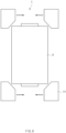
- FIG. 1 is a plan view of an apparatus 1 for sealing an electrode assembly according to an embodiment.
- an apparatus 1 for sealing an electrode assembly may be disposed outside an electrode assembly A to seal the electrode assembly A.
- the sealing apparatus 1 may be disposed at each corner of the electrode assembly A to seal each corner of the electrode assembly A by applying a pressure and heat to the electrode assembly A.
- the sealing apparatus 1 may seal a separator S in a state, in which an electrode plate E is disposed inside the separator S, on the electrode assembly A constituted by the electrode plate E and the separator S to block the electrode plate from an external environment.
- main sealing in which each edge of the separator S is sealed may be performed.
- the sealing apparatus 1 may seal the corner of the electrode assembly A to prevent such a problem and more smoothly proceeding to the main sealing.
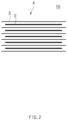
- FIG. 2 is a schematic view of the electrode assembly A according to an embodiment.
- the electrode assembly A may include a plurality of electrode plates E and a plurality of separators S, which are alternately stacked.
- the plurality of electrode plates E may include a form in which positive electrode plates and negative electrode plates are alternately disposed.
- the separator S may be inserted between the positive electrode plate and the negative electrode plate.
- the electrode assembly A may be impregnated with an electrolyte. Ions may actively move between the positive and negative plates through the electrolyte, and contact between the positive and negative plates may be blocked through the separator S to secure stability of the electrode assembly A.
- the separator S may include a synthetic resin material such as polyethylene or polypropylene to secure physical strength without chemically reacting with the ions.
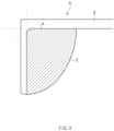
- FIG. 3 is an enlarged view illustrating the corner of the electrode assembly and a periphery of the corner according to an embodiment.
- the corner of the electrode plate E may include a cut portion. Specifically, a portion of each corner of the electrode plate E may be cut at a predetermined angle based on a direction in which the electrode plate E and the separator S are stacked, i.e., when the sealing apparatus 1 and the electrode assembly A are viewed from an upper side. According to this structure, in the process of sealing the corner of the separator S, the damage of the electrode plate E due to penetration of the sealing apparatus 1 into the inside of the separator S may be reduced.
- each corner of the electrode plate E may be cut at a predetermined angle a.
- each corner of the electrode plate E may be cut at a predetermined angle a with respect to a front direction or a full-width direction of the electrode plate E.
- the predetermined angle a may be within a range of 25 degrees to 35 degrees. That is, the corner may be formed so that an inclined surface is formed at an angle of 25 degrees to 35 degrees with respect to the front or rear surface of the electrode plate E. Alternatively, the corner may be formed so that an inclined surface is formed at an angle of 25 degrees to 35 degrees with respect to a side surface of the electrode plate E.
- the sealing apparatus 1 may include a pressing part 11 and a moving part 12.
- the pressing part 11 may apply a pressure to the plurality of separators S.
- a plurality of pressing parts 11 may be disposed at each corner of the separator S to apply a pressure to the plurality of separators S by being in contact with each corner of the separator S. Due to high-temperature heat by a heating part (not shown) described later and a high pressure of the pressing part 11, each corner of the separator S stacked with the electrode plate E may be sealed so that the electrode plate E is separated from the outside by the separator S.
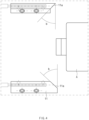
- FIG. 4 is a top view of the electrode assembly A and the pressing part 11 according to an embodiment.
- the pressing part 11 may include a pressing surface 11a that is parallel to the cut corner of the electrode plate E.
- the pressing surface 11a to which the pressing part 11 applies the pressure
- the surface of the cut corner of the electrode plate E which faces the pressing surface 11a
- the pressing surface 11a and the cut portion of the corner of the electrode plate E may face each other based on the direction in which the electrode plate E and the separator S are stacked, i.e., when the sealing apparatus 1 and the electrode assembly A are viewed from the upper side.
- the pressing surface 11a and the cut portion of the corner of the electrode plate E may be parallel to each other. More specifically, as illustrated in FIG. 4 , the pressing surface 11a of the pressing part 11 may have a shape including an inclined surface at a predetermined angle b.
- the predetermined angle b of the inclined surface may be an angle with respect to a full-length direction or a full-width direction of the pressing surface 11a.
- the pressing surface 11a of the pressing part 11 may be angled at an angle of 25 degrees to 35 degrees with respect to the full-length direction of the electrode assembly A.
- the inclined angle of the pressing surface 11a of the pressing part 11 with respect to both side surfaces of the electrode assembly may be 25 degrees to 35 degrees.
- the pressing surface 11a of the pressing part 11 may be angled at an angle of 25 degrees to 35 degrees with respect to the full-width direction of the electrode assembly A.
- the inclined angle of the pressing surface 11a of the pressing part 11 with respect to a front or rear surface of the electrode assembly A may be 25 degrees to 35 degrees.
- the angle of the pressing surface may be designed differently according to a cut angle of the cut surface of the corner of the electrode plate E. That is, when the corner of the electrode plate E includes the cut surface of 30 degrees with respect to the full-width direction, the pressing surface may also include an inclined surface of 30 degrees with respect to the full-width direction of the pressing part 11.
- the pressing surface 11a of the pressing part 11 when the pressing surface 11a of the pressing part 11 is angled at an angle of less than 25 degrees with respect to the full-width direction of the electrode assembly A, the pressing surface 11a may be in contact with each corner of the electrode assembly A so as to be almost parallel to the front or rear surface of the electrode assembly A, and thus, a sealing angle of the electrode assembly A may be deteriorated.
- the pressing surface 11a since the pressing surface 11a is formed so as not to correspond to the inclined surface of the corner of the electrode plate E, the electrode plate E may be worn or broken during the process of sealing each corner of the electrode assembly A.
- the pressing surface 11a of the pressing part 11 is angled at an angle of more than 35 degrees with respect to the full-width direction of the electrode assembly A, that is, the pressing surface 11a is angled at an angle of 35 degrees to 45 degrees with respect to the full-width direction of the electrode assembly A, since the pressing surface 11a is disposed to be excessively inclined with respect to the front or rear surface of the electrode assembly A, and the pressing surface 11a is formed so as not to correspond to the inclined surface of the corner of the electrode plate E, the electrode plate E may be worn or broken during the process of sealing each corner of the electrode assembly A.
- the pressing surface 11a of the pressing part 11 when the pressing surface 11a of the pressing part 11 is angled at an angle of less than 25 degrees with respect to the full-length direction of the electrode assembly A, the pressing surface 11a may be in contact with each corner of the electrode assembly A so as to be almost parallel to the side surface of the electrode assembly A, and thus, a sealing angle of the electrode assembly A may be deteriorated.
- the pressing surface 11a since the pressing surface 11a is formed so as not to correspond to the inclined surface of the corner of the electrode plate E, the electrode plate E may be worn or broken during the process of sealing each corner of the electrode assembly A.
- the pressing surface 11a of the pressing part 11 is angled at an angle of more than 35 degrees with respect to the full-length direction of the electrode assembly A, that is, the pressing surface 11a is angled at an angle of 35 degrees to 45 degrees with respect to the full-length direction of the electrode assembly A, since the pressing surface 11a is disposed to be excessively inclined with respect to the side surface of the electrode assembly A, and the pressing surface 11a is formed so as not to correspond to the inclined surface of the corner of the electrode plate E, the electrode plate E may be worn or broken during the process of sealing each corner of the electrode assembly A.
- the pressing part 11 may also apply the pressure to the electrode plate E inside the separator S. According to this structure, the pressure applied to the electrode plate E by the pressing part 11 may be more reduced. In other words, since the pressing surface of the pressing part 11 and the cut surface of the corner of the electrode plate E are parallel to each other, a wider surface of the corner of the electrode plate E may undergo the pressure by the pressing surface. In this structure, the pressure of the pressing part 11 to the electrode plate E may be minimized.
- the damage and abrasion of the electrode plate E, which occur during the sealing process may be reduced to produce a product having higher quality.
- the bending and cracking of the electrode plate E due to the contact between the pressing part 11 and the electrode plate E may be more prevented to improve yield of a finished product.
- the moving part 12 may allow the pressing part 11 to move toward the electrode assembly A.
- the moving part 12 may be connected to the pressing part 11 to allow the pressing part 11 to move at various angles and position using a transport means such as a motor.
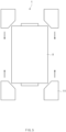
- FIG. 5 is a schematic view illustrating movement of the pressing part 11 according to an embodiment.
- the moving part 12 may allow the pressing part 11 to move in a first direction parallel to the full-length direction of the electrode assembly A so that the pressing part 11 presses the plurality of separators S.
- the moving part 12 may allow the pressing part 11 to move toward the electrode assembly A in the same direction as a longitudinal direction of the electrode assembly A. That is, in FIG. 5 , the moving part 12 may allow the pressing part 11 disposed at upper and lower sides of the electrode assembly A to move in downward and upward directions.
- FIG. 6 is a schematic view illustrating movement of the pressing part 11 according to an embodiment.
- the moving part 12 may allow the pressing part 11 to move in a second direction parallel to the full-width direction of the electrode assembly A.
- the moving part 12 may allow the pressing part 11 to move toward the electrode assembly A in a direction perpendicular to the longitudinal direction of the electrode assembly A. That is, in FIG. 6 , the moving part 12 may allow each of the pressing parts 11 disposed at both sides of the electrode assembly A to move toward the electrode assembly A.
- the moving part 12 may allow the pressing part 11 to sequentially move in the first direction and the second direction. That is, the moving part 12 may allow the pressing part 11 to initially move in the first direction and then sequentially move in the second direction.
- the moving order of the moving part 12 may not be limited to the above order and may allow the pressing part 11 to move in the first direction after allowing the pressing part 11 to move in the second direction.
- the moving part 12 may allow the pressing part 11 to simultaneously move in the first direction and the second direction, thereby realizing more effective movement and contact of the pressing part 11.
- the sealing apparatus according to the related art may operate only in the first direction, which is the longitudinal direction of the electrode assembly to realize a mechanism in which the pressing part moves to the electrode assembly so that the pressure is applied.
- the sealing apparatus 1 according to an embodiment may more accurately perform the sealing process by the moving part 12.
- the sealing apparatus according to the related art has a problem in that the pressing part operates only in one direction that is the longitudinal direction of the electrode assembly, and thus, the separator of the electrode assembly is widened, and a gap occurs.
- the apparatus 1 for sealing the electrode assembly may allow the pressing part 11 to move in the second direction after moving in the first direction or moves in the first direction after moving in the second direction so that the pressing part moves depending on circumstances to more flexible and accurate sealing process. Therefore, the apparatus 1 for sealing the electrode assembly may prevent the problem such as the lifting and cracking of the separator S that occur during the sealing process from occurring.
- the apparatus 1 for sealing the electrode assembly allows the pressing part 11 to move in the first and second directions, the apparatus 1 for sealing the electrode assembly may improve the efficiency of the corner sealing process and the quality of the manufactured product.
- the sealing apparatus 1 may further include a heating part (not shown).
- the heating part (not shown) may be connected to the pressing part 11 to apply heat to the electrode assembly A.
- the heating part (not shown) may generate heat by including a heating means to transfer the heat generated through the physically connected pressing part 11 to the electrode assembly A.
- the electrode assembly A receiving high-temperature heat from the heating part (not shown) may be sealed through a thermal fusion process.
- FIG. 7 is a flowchart illustrating a method for sealing an electrode assembly according to another embodiment.
- the electrode assembly A constituted by an electrode plate E and a separator S may be sealed.
- the separator S may be sealed in a state in which the electrode plate E is disposed inside the separator S.
- each corner of the electrode assembly A that is, each corner of the separator S may be sealed through the method 2 for sealing the electrode assembly, and the electrode assembly A having each corner sealed may be completely sealed because a main sealing process is performed also.
- the method for sealing the electrode assembly may include a moving process (S21) and a sealing process (S22).
- a sealing apparatus 1 for sealing a corner of a separator S includes a moving part 12 and a pressing part 11, and the pressing part 11 may move by the moving part 12 so as to be in contact with the electrode assembly A.
- the plurality of separators S may be sealed by pressing and heating the plurality of separators S in the state in which the pressing part 11 is in contact with the electrode assembly A.
- the pressing part 11 may include a pressing surface parallel to a cut corner of the electrode plate E.
- the pressing surface to which the pressing part 11 applies a pressure and the cut surface of the corner of the electrode plate E, which faces the pressing surface may be parallel to each other. More specifically, the pressing surface of the pressing part 11 may be angled at an angle of 25 degrees to 35 degrees with respect to the full-length direction and the full-width direction of the electrode assembly A.
- the cut angle of the cut surface of the corner of the electrode plate E may be angled at an angle of 25 degrees to 35 degrees with respect to the full-length direction and the full-width direction of the electrode assembly A. That is, the angle of the pressing surface 11a may be designed differently according to the cut angle of the cut surface of the corner of the electrode plate E, and thus, the respective surfaces may be parallel to each other.
- the pressure of the pressing part 11, which is applied to the electrode plate E during the sealing process, may be reduced to more prevent the electrode plate E from being bent and cracked.
- the pressing part 11 may move in the first direction parallel to the longitudinal direction of the electrode assembly A and the second direction parallel to the width direction of the electrode assembly A.
- the pressing part 11 may operate only in the longitudinal direction of the electrode assembly A.
- the moving part 12 may allow the press part 11 to move in the longitudinal direction of the electrode assembly A and the direction perpendicular to the longitudinal direction to prevent the separator S of the electrode assembly A from being widened, or prevent the gap from occurring.
Landscapes
- Chemical & Material Sciences (AREA)
- Chemical Kinetics & Catalysis (AREA)
- Electrochemistry (AREA)
- General Chemical & Material Sciences (AREA)
- Engineering & Computer Science (AREA)
- Manufacturing & Machinery (AREA)
- Secondary Cells (AREA)
- Battery Electrode And Active Subsutance (AREA)
Abstract
Description
- The present application claims the benefit of the priority of
Korean Patent Application Nos. 10-2022-0027739, filed on March 03, 2022 10-2023-0028024, filed on March 02, 2023 - The present invention relates to an apparatus and method for sealing an electrode assembly, and more particularly, to an apparatus and method for sealing an electrode assembly, which seals a plurality of separators provided in an electrode assembly with each other.
- In general, secondary batteries include nickel-cadmium batteries, nickel-hydrogen batteries, lithium ion batteries, and lithium ion polymer batteries. Such a secondary battery is being applied to be used in small-sized products such as digital cameras, P-DVDs, MP3Ps, mobile phones, PDAs, portable game devices, power tools, E-bikes, and the like as well as large-sized products requiring high power such as electric vehicles and hybrid vehicles, power storage devices for storing surplus power or renewable energy, and backup power storage devices.
- In general, in order to manufacture the secondary battery, first, electrode active material slurry is applied to a positive electrode collector and a negative electrode collector to manufacture a positive electrode and a negative electrode. Then, the electrodes are stacked on both sides of a separator to form an electrode assembly. Also, the electrode assembly is accommodated in a battery case, and then the battery case is sealed after an electrolyte is injected therein.
- Such a secondary battery is classified into a pouch-type secondary battery and a can-type secondary battery according to a material of a case accommodating the electrode assembly. In the pouch-type secondary battery, an electrode assembly is accommodated in a pouch made of a flexible polymer material. Also, in the can-type secondary battery, an electrode assembly is accommodated in a case made of a metal or plastic material.
- In a process of sealing an electrode inside the separator after stacking the electrode and the separator, a sealing apparatus that generates a high temperature and high pressure is used. The sealing apparatus applies a pressure and heat to the separator to seal the electrode inside the separator. Particularly, when the sealing apparatus seals each corner of the separator, an elaborate operation is required so as not to damage the electrode assembly. Specifically, during the corner sealing operation of the sealing apparatus, problems may occur in the process, such as bending and cracking of the electrode due to contact between the sealing apparatus and the electrode, or lifting of the separator by the sealing apparatus.
- In order to prevent these problems, there is a need for a sealing apparatus and a sealing method, which are capable of preventing the problem of electrode damage and increasing process efficiency by sealing the separator more elaborately.
- One object of the present invention for solving the above problem is to provide an apparatus and method for sealing an electrode assembly, which accurately seals a separator of the electrode assembly to prevent an electrode from being damaged and improve process efficiency.
- In an apparatus for sealing an electrode assembly according to an embodiment of the present invention, a plurality of separators may be sealed to each other in the electrode assembly in which a plurality of electrode plates and the plurality of separators are alternately stacked. The apparatus for sealing the electrode assembly may include a pressing part configured to apply a pressure to the plurality of separators, and a moving part configured to allow the pressing part to move toward the electrode assembly, wherein the pressing part may include a pressing surface that is parallel to a cut corner of each of the electrode plate.
- The pressing surface of the pressing part may be angled at an angle of 25 degrees to 35 degrees in a full-length direction of the electrode assembly.
- The pressing surface of the pressing part may be angled at an angle of 25 degrees to 35 degrees in a full-width direction of the electrode assembly.
- The pressing part may be provided in plurality to be respectively disposed at a plurality of corners of the electrode assembly.
- The moving part may allow the pressing part to move in a first direction parallel to a full-length direction of the electrode assembly and a second direction parallel to a full-width direction of the electrode assembly so as to press the plurality of separators.
- The moving part may allow the pressing part to sequentially move in the first and second directions.
- In a method for sealing an electrode assembly according to an embodiment of the present invention, a plurality of separators may be sealed to each other in the electrode assembly in which a plurality of electrode plates and the plurality of separators are alternately stacked. The method for sealing the electrode assembly may include a moving process of allowing a pressing part to move toward the electrode assembly and a sealing process of allowing the pressing part to press and heat the plurality of separators so as to seal the plurality of separators to each other in a state of being in contact with the electrode assembly, wherein the pressing part may include a pressing surface parallel to a cut corner of the electrode plate.
- the pressing surface of the pressing part is angled at an angle of 25 degrees to 35 degrees in a full-length direction and in a full-width direction of the electrode assembly.
- The pressing part may be provided in plurality to be respectively disposed at a plurality of corners of the electrode assembly.
- In the moving process and/or sealing process, the pressing part may move in a first direction parallel to the full-length direction of the electrode assembly and a second direction parallel to the full-width direction of the electrode assembly.
- According to the preferred embodiment of the present invention, the pressing surface of the pressing part facing the electrode assembly may be designed to be parallel to the cut corner of the electrode plate, thereby minimizing the bending and cracking of the electrode, which occur during the sealing process.
- According to the preferred embodiment of the present invention, the pressing part pressing the electrode assembly may two-dimensionally move by the moving part to perform the sealing process, and thus, the sealing process may be more accurately performed to improve the process accuracy.
- In addition, the effects that are obvious to those skilled in the art may be predicted from the configurations according to the embodiment of the present invention.
- The following drawings attached in this specification illustrate a preferred embodiment of the present invention and function to make further understood the technical spirit of the present invention along with the detailed description of the invention, and thus, the present invention should not be construed as being limited to only the drawings.
-
FIG. 1 is a plan view of an apparatus for sealing an electrode assembly according to an embodiment. -
FIG. 2 is a cross-sectional view of the electrode assembly according to an embodiment. -
FIG. 3 is an enlarged view illustrating a corner of the electrode assembly and a periphery of the corner according to an embodiment. -
FIG. 4 is a top view of the electrode assembly and a pressing part according to an embodiment. -
FIGS. 5 and6 are schematic views illustrating movement of the pressing part according to an embodiment. -
FIG. 7 is a flowchart illustrating a method for sealing an electrode assembly according to another embodiment. - Hereinafter, preferred embodiments of the present invention will be described in detail with reference to the accompanying drawings so that those of ordinary skill in the art can easily carry out the present invention. However, the present invention may be implemented in several different forms and is not limited or restricted by the following examples.
- In order to clearly explain the present invention, detailed descriptions of portions that are irrelevant to the description or related known technologies that may unnecessarily obscure the gist of the present invention have been omitted, and in the present specification, reference symbols are added to components in each drawing. In this case, the same or similar reference numerals are assigned to the same or similar elements throughout the specification.
- Also, terms or words used in this specification and claims should not be restrictively interpreted as ordinary meanings or dictionary-based meanings, but should be interpreted as meanings and concepts conforming to the scope of the present invention on the basis of the principle that an inventor can properly define the concept of a term to describe and explain his or her invention in the best ways.
-
FIG. 1 is a plan view of anapparatus 1 for sealing an electrode assembly according to an embodiment. - Referring to
FIG. 1 , anapparatus 1 for sealing an electrode assembly (hereinafter, referred to as a 'sealing apparatus') may be disposed outside an electrode assembly A to seal the electrode assembly A. For example, thesealing apparatus 1 may be disposed at each corner of the electrode assembly A to seal each corner of the electrode assembly A by applying a pressure and heat to the electrode assembly A. Specifically, thesealing apparatus 1 may seal a separator S in a state, in which an electrode plate E is disposed inside the separator S, on the electrode assembly A constituted by the electrode plate E and the separator S to block the electrode plate from an external environment. After the corner sealing of the electrode assembly A, i.e., the corner sealing in which each corner of the electrode assembly A is sealed, main sealing in which each edge of the separator S is sealed may be performed. - Since the main sealing is sequentially performed after the corner sealing, it may be important to prevent the electrode plate E from being damaged, or prevent the separator S being lifted during the corner sealing process. The
sealing apparatus 1 may seal the corner of the electrode assembly A to prevent such a problem and more smoothly proceeding to the main sealing. -
FIG. 2 is a schematic view of the electrode assembly A according to an embodiment. - Referring to
FIG. 2 , the electrode assembly A may include a plurality of electrode plates E and a plurality of separators S, which are alternately stacked. The plurality of electrode plates E may include a form in which positive electrode plates and negative electrode plates are alternately disposed. In this case, the separator S may be inserted between the positive electrode plate and the negative electrode plate. The electrode assembly A may be impregnated with an electrolyte. Ions may actively move between the positive and negative plates through the electrolyte, and contact between the positive and negative plates may be blocked through the separator S to secure stability of the electrode assembly A. The separator S may include a synthetic resin material such as polyethylene or polypropylene to secure physical strength without chemically reacting with the ions. -
FIG. 3 is an enlarged view illustrating the corner of the electrode assembly and a periphery of the corner according to an embodiment. - Referring to
FIG. 3 , the corner of the electrode plate E may include a cut portion. Specifically, a portion of each corner of the electrode plate E may be cut at a predetermined angle based on a direction in which the electrode plate E and the separator S are stacked, i.e., when thesealing apparatus 1 and the electrode assembly A are viewed from an upper side. According to this structure, in the process of sealing the corner of the separator S, the damage of the electrode plate E due to penetration of thesealing apparatus 1 into the inside of the separator S may be reduced. - In
FIG. 3 , each corner of the electrode plate E may be cut at a predetermined angle a. For example, each corner of the electrode plate E may be cut at a predetermined angle a with respect to a front direction or a full-width direction of the electrode plate E. The predetermined angle a may be within a range of 25 degrees to 35 degrees. That is, the corner may be formed so that an inclined surface is formed at an angle of 25 degrees to 35 degrees with respect to the front or rear surface of the electrode plate E. Alternatively, the corner may be formed so that an inclined surface is formed at an angle of 25 degrees to 35 degrees with respect to a side surface of the electrode plate E. - The sealing
apparatus 1 may include apressing part 11 and a movingpart 12. - The
pressing part 11 may apply a pressure to the plurality of separators S. For example, a plurality ofpressing parts 11 may be disposed at each corner of the separator S to apply a pressure to the plurality of separators S by being in contact with each corner of the separator S. Due to high-temperature heat by a heating part (not shown) described later and a high pressure of thepressing part 11, each corner of the separator S stacked with the electrode plate E may be sealed so that the electrode plate E is separated from the outside by the separator S. -
FIG. 4 is a top view of the electrode assembly A and thepressing part 11 according to an embodiment. - Referring to
FIG. 4 , thepressing part 11 may include apressing surface 11a that is parallel to the cut corner of the electrode plate E. In other words, in the process, in which thepressing part 11 and the separator S are in contact with each other to apply a pressure, thepressing surface 11a, to which thepressing part 11 applies the pressure, and the surface of the cut corner of the electrode plate E, which faces thepressing surface 11a, may be parallel to each other. Specifically, thepressing surface 11a and the cut portion of the corner of the electrode plate E may face each other based on the direction in which the electrode plate E and the separator S are stacked, i.e., when thesealing apparatus 1 and the electrode assembly A are viewed from the upper side. In this case, thepressing surface 11a and the cut portion of the corner of the electrode plate E may be parallel to each other. More specifically, as illustrated inFIG. 4 , thepressing surface 11a of thepressing part 11 may have a shape including an inclined surface at a predetermined angle b. The predetermined angle b of the inclined surface may be an angle with respect to a full-length direction or a full-width direction of thepressing surface 11a. - For example, the
pressing surface 11a of thepressing part 11 may be angled at an angle of 25 degrees to 35 degrees with respect to the full-length direction of the electrode assembly A. In other words, the inclined angle of thepressing surface 11a of thepressing part 11 with respect to both side surfaces of the electrode assembly may be 25 degrees to 35 degrees. - Alternatively, the
pressing surface 11a of thepressing part 11 may be angled at an angle of 25 degrees to 35 degrees with respect to the full-width direction of the electrode assembly A. In other words, the inclined angle of thepressing surface 11a of thepressing part 11 with respect to a front or rear surface of the electrode assembly A may be 25 degrees to 35 degrees. - In other words, the angle of the pressing surface may be designed differently according to a cut angle of the cut surface of the corner of the electrode plate E. That is, when the corner of the electrode plate E includes the cut surface of 30 degrees with respect to the full-width direction, the pressing surface may also include an inclined surface of 30 degrees with respect to the full-width direction of the
pressing part 11. - Specifically, when the
pressing surface 11a of thepressing part 11 is angled at an angle of less than 25 degrees with respect to the full-width direction of the electrode assembly A, thepressing surface 11a may be in contact with each corner of the electrode assembly A so as to be almost parallel to the front or rear surface of the electrode assembly A, and thus, a sealing angle of the electrode assembly A may be deteriorated. In addition, since thepressing surface 11a is formed so as not to correspond to the inclined surface of the corner of the electrode plate E, the electrode plate E may be worn or broken during the process of sealing each corner of the electrode assembly A. - In addition, when the
pressing surface 11a of thepressing part 11 is angled at an angle of more than 35 degrees with respect to the full-width direction of the electrode assembly A, that is, thepressing surface 11a is angled at an angle of 35 degrees to 45 degrees with respect to the full-width direction of the electrode assembly A, since thepressing surface 11a is disposed to be excessively inclined with respect to the front or rear surface of the electrode assembly A, and thepressing surface 11a is formed so as not to correspond to the inclined surface of the corner of the electrode plate E, the electrode plate E may be worn or broken during the process of sealing each corner of the electrode assembly A. - Similarly, when the
pressing surface 11a of thepressing part 11 is angled at an angle of less than 25 degrees with respect to the full-length direction of the electrode assembly A, thepressing surface 11a may be in contact with each corner of the electrode assembly A so as to be almost parallel to the side surface of the electrode assembly A, and thus, a sealing angle of the electrode assembly A may be deteriorated. In addition, since thepressing surface 11a is formed so as not to correspond to the inclined surface of the corner of the electrode plate E, the electrode plate E may be worn or broken during the process of sealing each corner of the electrode assembly A. - In addition, when the
pressing surface 11a of thepressing part 11 is angled at an angle of more than 35 degrees with respect to the full-length direction of the electrode assembly A, that is, thepressing surface 11a is angled at an angle of 35 degrees to 45 degrees with respect to the full-length direction of the electrode assembly A, since thepressing surface 11a is disposed to be excessively inclined with respect to the side surface of the electrode assembly A, and thepressing surface 11a is formed so as not to correspond to the inclined surface of the corner of the electrode plate E, the electrode plate E may be worn or broken during the process of sealing each corner of the electrode assembly A. - In the process, in which the
pressing part 11 presses the separator S, thepressing part 11 may also apply the pressure to the electrode plate E inside the separator S. According to this structure, the pressure applied to the electrode plate E by thepressing part 11 may be more reduced. In other words, since the pressing surface of thepressing part 11 and the cut surface of the corner of the electrode plate E are parallel to each other, a wider surface of the corner of the electrode plate E may undergo the pressure by the pressing surface. In this structure, the pressure of thepressing part 11 to the electrode plate E may be minimized. - As a result, since the pressure applied to the electrode plate E is minimized by the structure of the
pressing part 11, the damage and abrasion of the electrode plate E, which occur during the sealing process may be reduced to produce a product having higher quality. Specifically, the bending and cracking of the electrode plate E due to the contact between thepressing part 11 and the electrode plate E may be more prevented to improve yield of a finished product. - The moving
part 12 may allow thepressing part 11 to move toward the electrode assembly A. For example, the movingpart 12 may be connected to thepressing part 11 to allow thepressing part 11 to move at various angles and position using a transport means such as a motor. -
FIG. 5 is a schematic view illustrating movement of thepressing part 11 according to an embodiment. - Referring to
FIG. 5 , the movingpart 12 may allow thepressing part 11 to move in a first direction parallel to the full-length direction of the electrode assembly A so that thepressing part 11 presses the plurality of separators S. In other words, the movingpart 12 may allow thepressing part 11 to move toward the electrode assembly A in the same direction as a longitudinal direction of the electrode assembly A. That is, inFIG. 5 , the movingpart 12 may allow thepressing part 11 disposed at upper and lower sides of the electrode assembly A to move in downward and upward directions. -
FIG. 6 is a schematic view illustrating movement of thepressing part 11 according to an embodiment. - Referring to
FIG. 6 , the movingpart 12 may allow thepressing part 11 to move in a second direction parallel to the full-width direction of the electrode assembly A. In other words, the movingpart 12 may allow thepressing part 11 to move toward the electrode assembly A in a direction perpendicular to the longitudinal direction of the electrode assembly A. That is, inFIG. 6 , the movingpart 12 may allow each of thepressing parts 11 disposed at both sides of the electrode assembly A to move toward the electrode assembly A. - In an order in which the moving
part 12 allows thepressing part 11 to move, the movingpart 12 may allow thepressing part 11 to sequentially move in the first direction and the second direction. That is, the movingpart 12 may allow thepressing part 11 to initially move in the first direction and then sequentially move in the second direction. However, the moving order of the movingpart 12 may not be limited to the above order and may allow thepressing part 11 to move in the first direction after allowing thepressing part 11 to move in the second direction. Alternatively, the movingpart 12 may allow thepressing part 11 to simultaneously move in the first direction and the second direction, thereby realizing more effective movement and contact of thepressing part 11. - According to this operational principle, the sealing apparatus according to the related art may operate only in the first direction, which is the longitudinal direction of the electrode assembly to realize a mechanism in which the pressing part moves to the electrode assembly so that the pressure is applied. On the other hand, the sealing
apparatus 1 according to an embodiment may more accurately perform the sealing process by the movingpart 12. Specifically, the sealing apparatus according to the related art has a problem in that the pressing part operates only in one direction that is the longitudinal direction of the electrode assembly, and thus, the separator of the electrode assembly is widened, and a gap occurs. On the other hand, theapparatus 1 for sealing the electrode assembly according to an embodiment may allow thepressing part 11 to move in the second direction after moving in the first direction or moves in the first direction after moving in the second direction so that the pressing part moves depending on circumstances to more flexible and accurate sealing process. Therefore, theapparatus 1 for sealing the electrode assembly may prevent the problem such as the lifting and cracking of the separator S that occur during the sealing process from occurring. - As a result, since the
apparatus 1 for sealing the electrode assembly allows thepressing part 11 to move in the first and second directions, theapparatus 1 for sealing the electrode assembly may improve the efficiency of the corner sealing process and the quality of the manufactured product. - The sealing
apparatus 1 may further include a heating part (not shown). The heating part (not shown) may be connected to thepressing part 11 to apply heat to the electrode assembly A. For example, the heating part (not shown) may generate heat by including a heating means to transfer the heat generated through the physically connected pressingpart 11 to the electrode assembly A. The electrode assembly A receiving high-temperature heat from the heating part (not shown) may be sealed through a thermal fusion process. - Hereinafter, a method 2 for sealing an electrode assembly is disclosed. Descriptions of concepts that are partially duplicated with the configuration described above will be omitted.
-
FIG. 7 is a flowchart illustrating a method for sealing an electrode assembly according to another embodiment. - Hereinafter, a method for sealing an electrode assembly will be described as another embodiment of the present invention.
- Referring to
FIG. 7 , in the method for sealing the electrode assembly, the electrode assembly A constituted by an electrode plate E and a separator S may be sealed. Specifically, in the method for sealing the electrode assembly, the separator S may be sealed in a state in which the electrode plate E is disposed inside the separator S. In other words, each corner of the electrode assembly A, that is, each corner of the separator S may be sealed through the method 2 for sealing the electrode assembly, and the electrode assembly A having each corner sealed may be completely sealed because a main sealing process is performed also. - The method for sealing the electrode assembly may include a moving process (S21) and a sealing process (S22).
- In the moving process (S21), the
pressing part 11 may move toward the electrode assembly A. For example, asealing apparatus 1 for sealing a corner of a separator S includes a movingpart 12 and apressing part 11, and thepressing part 11 may move by the movingpart 12 so as to be in contact with the electrode assembly A. - In the sealing process (S22), the plurality of separators S may be sealed by pressing and heating the plurality of separators S in the state in which the
pressing part 11 is in contact with the electrode assembly A. In this case, thepressing part 11 may include a pressing surface parallel to a cut corner of the electrode plate E. Specifically, the pressing surface to which thepressing part 11 applies a pressure and the cut surface of the corner of the electrode plate E, which faces the pressing surface, may be parallel to each other. More specifically, the pressing surface of thepressing part 11 may be angled at an angle of 25 degrees to 35 degrees with respect to the full-length direction and the full-width direction of the electrode assembly A. Similarly, the cut angle of the cut surface of the corner of the electrode plate E may be angled at an angle of 25 degrees to 35 degrees with respect to the full-length direction and the full-width direction of the electrode assembly A. That is, the angle of thepressing surface 11a may be designed differently according to the cut angle of the cut surface of the corner of the electrode plate E, and thus, the respective surfaces may be parallel to each other. - According to this structure, the pressure of the
pressing part 11, which is applied to the electrode plate E during the sealing process, may be reduced to more prevent the electrode plate E from being bent and cracked. - In the moving process (S21) and/or the sealing process (S22), the
pressing part 11 may move in the first direction parallel to the longitudinal direction of the electrode assembly A and the second direction parallel to the width direction of the electrode assembly A. - According to this operational principle, in the
sealing apparatus 1 according to the related art, thepressing part 11 may operate only in the longitudinal direction of the electrode assembly A. On the other hand, in the method for sealing the electrode assembly according to an embodiment, the movingpart 12 may allow thepress part 11 to move in the longitudinal direction of the electrode assembly A and the direction perpendicular to the longitudinal direction to prevent the separator S of the electrode assembly A from being widened, or prevent the gap from occurring. - The above-disclosed subject matter is to be considered illustrative, and not restrictive, and the appended claims are intended to cover all such modifications, enhancements, and other embodiments, which fall within the true spirit and scope of the present disclosure.
- Thus, the embodiment of the present invention is to be considered illustrative, and not restrictive, and the technical spirit of the present invention is not limited to the foregoing embodiment.
- Therefore, the scope of the present disclosure is defined not by the detailed description of the invention but by the appended claims, and all differences within the scope will be construed as being included in the present disclosure.
-
- 1: Apparatus for sealing electrode assembly
- 11: Pressing part
- 12: Moving part
- 2: Method for sealing electrode assembly
- 21: Moving process
- 22: Sealing process
- A: Electrode assembly
- E: Electrode plate
- S: Separator
Claims (12)
- An apparatus for sealing an electrode assembly, which a plurality of separators are sealed to each other in the electrode assembly, in which a plurality of electrode plates and the plurality of separators are alternatively stacked, the apparatus comprising:a pressing part configured to apply a pressure to the plurality of separators; anda moving part configured to allow the pressing part to move toward the electrode assembly,wherein the pressing part comprises a pressing surface that is parallel to a cut corner of each of the electrode plate.
- The apparatus of claim 1, wherein the pressing surface is inclined to correspond to an inclined shape of the cut corner of the electrode plate.
- The apparatus of claim 2, wherein the pressing surface of the pressing part is angled at an angle of 25 degrees to 35 degrees in a full-length direction of the electrode assembly.
- The apparatus of claim 2, wherein the pressing surface of the pressing part is angled at an angle of 25 degrees to 35 degrees in a full-width direction of the electrode assembly.
- The apparatus of claim 1, wherein the pressing part is provided in plurality to be respectively disposed at a plurality of corners of the electrode assembly.
- The apparatus of claim 5, wherein the moving part allows the pressing part to move in a first direction parallel to a full-length direction of the electrode assembly and a second direction parallel to a full-width direction of the electrode assembly so as to press the plurality of separators.
- The apparatus of claim 6, wherein the moving part allows the pressing part to sequentially move in the first and second directions.
- A method for sealing an electrode assembly, which a plurality of separators are sealed to each other in the electrode assembly, in which a plurality of electrode plates and the plurality of separators are alternatively stacked, the method comprising:a moving process of allowing a pressing part to move toward the electrode assembly; anda sealing process of allowing the pressing part to press and heat the plurality of separators so as to seal the plurality of separators to each other in a state of being in contact with the electrode assembly,wherein the pressing part comprises a pressing surface parallel to a cut corner of the electrode plate.
- The method of claim 8, wherein the pressing surface is inclined to correspond to an inclined shape of the cut corner of the electrode plate.
- The method of claim 9, wherein the pressing surface of the pressing part is angled at an angle of 25 degrees to 35 degrees in a full-length direction or full-width direction of the electrode assembly.
- The method of claim 9, wherein the pressing part is provided in plurality to be respectively disposed at a plurality of corners of the electrode assembly.
- The method of claim 9, wherein, in the moving process and/or sealing process, the pressing part moves in a first direction parallel to the full-length direction of the electrode assembly and a second direction parallel to the full-width direction of the electrode assembly.
Applications Claiming Priority (3)
| Application Number | Priority Date | Filing Date | Title |
|---|---|---|---|
| KR20220027739 | 2022-03-03 | ||
| KR1020230028024A KR102942792B1 (en) | 2022-03-03 | 2023-03-02 | Sealing device and sealing method of electrode assembly |
| PCT/KR2023/002946 WO2023167543A1 (en) | 2022-03-03 | 2023-03-03 | Electrode assembly sealing device and sealing method |
Publications (2)
| Publication Number | Publication Date |
|---|---|
| EP4489155A1 true EP4489155A1 (en) | 2025-01-08 |
| EP4489155A4 EP4489155A4 (en) | 2025-09-03 |
Family
ID=87884057
Family Applications (1)
| Application Number | Title | Priority Date | Filing Date |
|---|---|---|---|
| EP23763741.8A Pending EP4489155A4 (en) | 2022-03-03 | 2023-03-03 | Electrode assembly sealing device and sealing method |
Country Status (4)
| Country | Link |
|---|---|
| US (1) | US20250174703A1 (en) |
| EP (1) | EP4489155A4 (en) |
| JP (1) | JP7753611B2 (en) |
| WO (1) | WO2023167543A1 (en) |
Family Cites Families (13)
| Publication number | Priority date | Publication date | Assignee | Title |
|---|---|---|---|---|
| JP6079773B2 (en) | 2012-03-30 | 2017-02-15 | 日本電気株式会社 | Sheet laminating apparatus and sheet laminating method |
| JP6142525B2 (en) | 2012-12-25 | 2017-06-07 | 日産自動車株式会社 | Electrode position detector |
| KR101595621B1 (en) * | 2013-09-27 | 2016-02-18 | 주식회사 엘지화학 | Method for electrode assembly |
| JP6290071B2 (en) | 2014-11-28 | 2018-03-07 | プライムアースEvエナジー株式会社 | Battery electrode plate manufacturing apparatus and battery electrode plate manufacturing method |
| KR102099907B1 (en) * | 2016-03-21 | 2020-04-10 | 주식회사 엘지화학 | Battery cell and pouch sealing apparatus for sealing the battery cell |
| KR20170138636A (en) * | 2016-06-08 | 2017-12-18 | 주식회사 엘지화학 | Method for Electrode Assembly of Irregular Structure and Electrode Assembly Having Irregular Structure |
| KR102347884B1 (en) * | 2017-10-17 | 2022-01-06 | 주식회사 엘지에너지솔루션 | Sealing Block to Prevent Crack of Pouch-Type Secondary Battery, Pouch-Type Battery Case and Sealing Method for Pouch-Type Battery Case Using thereof |
| JP6930397B2 (en) | 2017-11-29 | 2021-09-01 | 株式会社豊田自動織機 | Laminating equipment |
| KR102320016B1 (en) * | 2017-12-15 | 2021-11-02 | 주식회사 엘지에너지솔루션 | Manufacturin method of rechargeable battery |
| KR102909964B1 (en) * | 2020-06-04 | 2026-01-08 | 주식회사 엘지에너지솔루션 | The Apparatus And The Method For Manufacturing Electrode Assembly |
| CN112001912B (en) | 2020-08-27 | 2024-04-05 | 北京百度网讯科技有限公司 | Target detection method and device, computer system and readable storage medium |
| KR20210043481A (en) * | 2020-10-26 | 2021-04-21 | 주식회사 클레버 | Apparatus for forming sealing portion of secondary battery pouch |
| KR102639168B1 (en) | 2021-08-20 | 2024-02-20 | 인제대학교 산학협력단 | A method and apparatus for providing services in a virtual desktop environment |
-
2023
- 2023-03-03 JP JP2024548685A patent/JP7753611B2/en active Active
- 2023-03-03 US US18/841,060 patent/US20250174703A1/en active Pending
- 2023-03-03 WO PCT/KR2023/002946 patent/WO2023167543A1/en not_active Ceased
- 2023-03-03 EP EP23763741.8A patent/EP4489155A4/en active Pending
Also Published As
| Publication number | Publication date |
|---|---|
| JP7753611B2 (en) | 2025-10-15 |
| EP4489155A4 (en) | 2025-09-03 |
| JP2025505810A (en) | 2025-02-28 |
| WO2023167543A1 (en) | 2023-09-07 |
| US20250174703A1 (en) | 2025-05-29 |
Similar Documents
| Publication | Publication Date | Title |
|---|---|---|
| US12057545B2 (en) | Pouch exterior material for secondary battery, pouch type secondary battery using the same, and method of manufacturing the same | |
| US11935997B2 (en) | Pouch exterior for secondary battery, pouch-type secondary battery using the pouch exterior, and method of manufacturing the pouch-type secondary battery | |
| KR102619201B1 (en) | Secondary Battery and Battery Module Having the Same | |
| EP2869361B1 (en) | Sealing tool for pouch-type secondary battery | |
| EP3567649A1 (en) | Pouch-type battery side part sealing method including two-step sealing process | |
| US20150111090A1 (en) | Secondary battery and manufacturing method thereof | |
| EP4357100B1 (en) | Molding apparatus, molding method | |
| CN104412409A (en) | secondary battery | |
| US10347873B2 (en) | Arrangement of multiple galvanic elements stacked in a housing, and battery which includes such an arrangement of galvanic elements | |
| KR20200058173A (en) | Secondary battery | |
| US10446807B2 (en) | Secondary battery | |
| JP2008091100A (en) | Square lithium-ion battery | |
| US20240297333A1 (en) | Battery cell pressurization device | |
| KR20160115167A (en) | Manufacturing Method of Battery Cell Having Bent Sealing Surplus Portion | |
| US20250174703A1 (en) | Apparatus and Method for Sealing Electrode Assembly | |
| KR102942792B1 (en) | Sealing device and sealing method of electrode assembly | |
| KR20220102010A (en) | Battery cell and method of manufacturing the same | |
| CN118805280A (en) | Apparatus and method for sealing an electrode assembly | |
| KR101755073B1 (en) | Secondary battery and method for manufacture the same | |
| US20240332687A1 (en) | Battery cell, manufacturing device for battery cell and manufacturing method of battery cell | |
| US20230070655A1 (en) | Battery Cell and Manufacturing Device for the Same | |
| EP4571953A1 (en) | Pouch-type battery case and forming device therefor | |
| EP4629367A2 (en) | Apparatus for forming folding guide line and battery cell | |
| EP4517945A1 (en) | Pouch-type battery case, pouch-type secondary battery comprising same, method for manufacturing pouch-type battery case, and molding jig for manufacturing pouch-type battery case | |
| US20250300279A1 (en) | Pouch-Type Battery Case and Pouch-Type Secondary Battery Including the Same, Method for Pouch-Type Battery Case, and Forming Jig for Manufacturing Pouch-Type Battery Case |
Legal Events
| Date | Code | Title | Description |
|---|---|---|---|
| STAA | Information on the status of an ep patent application or granted ep patent |
Free format text: STATUS: THE INTERNATIONAL PUBLICATION HAS BEEN MADE |
|
| PUAI | Public reference made under article 153(3) epc to a published international application that has entered the european phase |
Free format text: ORIGINAL CODE: 0009012 |
|
| STAA | Information on the status of an ep patent application or granted ep patent |
Free format text: STATUS: REQUEST FOR EXAMINATION WAS MADE |
|
| 17P | Request for examination filed |
Effective date: 20240809 |
|
| AK | Designated contracting states |
Kind code of ref document: A1 Designated state(s): AL AT BE BG CH CY CZ DE DK EE ES FI FR GB GR HR HU IE IS IT LI LT LU LV MC ME MK MT NL NO PL PT RO RS SE SI SK SM TR |
|
| DAV | Request for validation of the european patent (deleted) | ||
| DAX | Request for extension of the european patent (deleted) | ||
| A4 | Supplementary search report drawn up and despatched |
Effective date: 20250804 |
|
| RIC1 | Information provided on ipc code assigned before grant |
Ipc: H01M 10/04 20060101AFI20250729BHEP Ipc: H01M 50/463 20210101ALI20250729BHEP Ipc: H01M 10/0585 20100101ALI20250729BHEP |