EP4488876A1 - Lesen eines rfid-transponders auf einem objekt in einer vorrichtung - Google Patents
Lesen eines rfid-transponders auf einem objekt in einer vorrichtung Download PDFInfo
- Publication number
- EP4488876A1 EP4488876A1 EP24180960.7A EP24180960A EP4488876A1 EP 4488876 A1 EP4488876 A1 EP 4488876A1 EP 24180960 A EP24180960 A EP 24180960A EP 4488876 A1 EP4488876 A1 EP 4488876A1
- Authority
- EP
- European Patent Office
- Prior art keywords
- rfid
- rfid transponder
- antenna
- resonant structure
- wall
- Prior art date
- Legal status (The legal status is an assumption and is not a legal conclusion. Google has not performed a legal analysis and makes no representation as to the accuracy of the status listed.)
- Withdrawn
Links
Images


Classifications
-
- G—PHYSICS
- G06—COMPUTING OR CALCULATING; COUNTING
- G06K—GRAPHICAL DATA READING; PRESENTATION OF DATA; RECORD CARRIERS; HANDLING RECORD CARRIERS
- G06K19/00—Record carriers for use with machines and with at least a part designed to carry digital markings
- G06K19/06—Record carriers for use with machines and with at least a part designed to carry digital markings characterised by the kind of the digital marking, e.g. shape, nature, code
- G06K19/067—Record carriers with conductive marks, printed circuits or semiconductor circuit elements, e.g. credit or identity cards also with resonating or responding marks without active components
-
- G—PHYSICS
- G06—COMPUTING OR CALCULATING; COUNTING
- G06K—GRAPHICAL DATA READING; PRESENTATION OF DATA; RECORD CARRIERS; HANDLING RECORD CARRIERS
- G06K19/00—Record carriers for use with machines and with at least a part designed to carry digital markings
- G06K19/06—Record carriers for use with machines and with at least a part designed to carry digital markings characterised by the kind of the digital marking, e.g. shape, nature, code
- G06K19/067—Record carriers with conductive marks, printed circuits or semiconductor circuit elements, e.g. credit or identity cards also with resonating or responding marks without active components
- G06K19/07—Record carriers with conductive marks, printed circuits or semiconductor circuit elements, e.g. credit or identity cards also with resonating or responding marks without active components with integrated circuit chips
- G06K19/077—Constructional details, e.g. mounting of circuits in the carrier
-
- G—PHYSICS
- G06—COMPUTING OR CALCULATING; COUNTING
- G06K—GRAPHICAL DATA READING; PRESENTATION OF DATA; RECORD CARRIERS; HANDLING RECORD CARRIERS
- G06K7/00—Methods or arrangements for sensing record carriers, e.g. for reading patterns
- G06K7/10—Methods or arrangements for sensing record carriers, e.g. for reading patterns by electromagnetic radiation, e.g. optical sensing; by corpuscular radiation
- G06K7/10009—Methods or arrangements for sensing record carriers, e.g. for reading patterns by electromagnetic radiation, e.g. optical sensing; by corpuscular radiation sensing by radiation using wavelengths larger than 0.1 mm, e.g. radio-waves or microwaves
- G06K7/10297—Methods or arrangements for sensing record carriers, e.g. for reading patterns by electromagnetic radiation, e.g. optical sensing; by corpuscular radiation sensing by radiation using wavelengths larger than 0.1 mm, e.g. radio-waves or microwaves arrangements for handling protocols designed for non-contact record carriers such as RFIDs NFCs, e.g. ISO/IEC 14443 and 18092
-
- G—PHYSICS
- G06—COMPUTING OR CALCULATING; COUNTING
- G06K—GRAPHICAL DATA READING; PRESENTATION OF DATA; RECORD CARRIERS; HANDLING RECORD CARRIERS
- G06K19/00—Record carriers for use with machines and with at least a part designed to carry digital markings
- G06K19/06—Record carriers for use with machines and with at least a part designed to carry digital markings characterised by the kind of the digital marking, e.g. shape, nature, code
- G06K19/067—Record carriers with conductive marks, printed circuits or semiconductor circuit elements, e.g. credit or identity cards also with resonating or responding marks without active components
- G06K19/07—Record carriers with conductive marks, printed circuits or semiconductor circuit elements, e.g. credit or identity cards also with resonating or responding marks without active components with integrated circuit chips
- G06K19/077—Constructional details, e.g. mounting of circuits in the carrier
- G06K19/07749—Constructional details, e.g. mounting of circuits in the carrier the record carrier being capable of non-contact communication, e.g. constructional details of the antenna of a non-contact smart card
-
- G—PHYSICS
- G06—COMPUTING OR CALCULATING; COUNTING
- G06K—GRAPHICAL DATA READING; PRESENTATION OF DATA; RECORD CARRIERS; HANDLING RECORD CARRIERS
- G06K19/00—Record carriers for use with machines and with at least a part designed to carry digital markings
- G06K19/06—Record carriers for use with machines and with at least a part designed to carry digital markings characterised by the kind of the digital marking, e.g. shape, nature, code
- G06K19/067—Record carriers with conductive marks, printed circuits or semiconductor circuit elements, e.g. credit or identity cards also with resonating or responding marks without active components
- G06K19/07—Record carriers with conductive marks, printed circuits or semiconductor circuit elements, e.g. credit or identity cards also with resonating or responding marks without active components with integrated circuit chips
- G06K19/077—Constructional details, e.g. mounting of circuits in the carrier
- G06K19/07749—Constructional details, e.g. mounting of circuits in the carrier the record carrier being capable of non-contact communication, e.g. constructional details of the antenna of a non-contact smart card
- G06K19/07758—Constructional details, e.g. mounting of circuits in the carrier the record carrier being capable of non-contact communication, e.g. constructional details of the antenna of a non-contact smart card arrangements for adhering the record carrier to further objects or living beings, functioning as an identification tag
-
- G—PHYSICS
- G06—COMPUTING OR CALCULATING; COUNTING
- G06K—GRAPHICAL DATA READING; PRESENTATION OF DATA; RECORD CARRIERS; HANDLING RECORD CARRIERS
- G06K19/00—Record carriers for use with machines and with at least a part designed to carry digital markings
- G06K19/06—Record carriers for use with machines and with at least a part designed to carry digital markings characterised by the kind of the digital marking, e.g. shape, nature, code
- G06K19/067—Record carriers with conductive marks, printed circuits or semiconductor circuit elements, e.g. credit or identity cards also with resonating or responding marks without active components
- G06K19/07—Record carriers with conductive marks, printed circuits or semiconductor circuit elements, e.g. credit or identity cards also with resonating or responding marks without active components with integrated circuit chips
- G06K19/077—Constructional details, e.g. mounting of circuits in the carrier
- G06K19/07749—Constructional details, e.g. mounting of circuits in the carrier the record carrier being capable of non-contact communication, e.g. constructional details of the antenna of a non-contact smart card
- G06K19/07771—Constructional details, e.g. mounting of circuits in the carrier the record carrier being capable of non-contact communication, e.g. constructional details of the antenna of a non-contact smart card the record carrier comprising means for minimising adverse effects on the data communication capability of the record carrier, e.g. minimising Eddy currents induced in a proximate metal or otherwise electromagnetically interfering object
-
- G—PHYSICS
- G06—COMPUTING OR CALCULATING; COUNTING
- G06K—GRAPHICAL DATA READING; PRESENTATION OF DATA; RECORD CARRIERS; HANDLING RECORD CARRIERS
- G06K7/00—Methods or arrangements for sensing record carriers, e.g. for reading patterns
- G06K7/10—Methods or arrangements for sensing record carriers, e.g. for reading patterns by electromagnetic radiation, e.g. optical sensing; by corpuscular radiation
- G06K7/10009—Methods or arrangements for sensing record carriers, e.g. for reading patterns by electromagnetic radiation, e.g. optical sensing; by corpuscular radiation sensing by radiation using wavelengths larger than 0.1 mm, e.g. radio-waves or microwaves
- G06K7/10316—Methods or arrangements for sensing record carriers, e.g. for reading patterns by electromagnetic radiation, e.g. optical sensing; by corpuscular radiation sensing by radiation using wavelengths larger than 0.1 mm, e.g. radio-waves or microwaves using at least one antenna particularly designed for interrogating the wireless record carriers
-
- H—ELECTRICITY
- H01—ELECTRIC ELEMENTS
- H01Q—ANTENNAS, i.e. RADIO AERIALS
- H01Q1/00—Details of, or arrangements associated with, antennas
- H01Q1/12—Supports; Mounting means
- H01Q1/22—Supports; Mounting means by structural association with other equipment or articles
- H01Q1/2208—Supports; Mounting means by structural association with other equipment or articles associated with components used in interrogation type services, i.e. in systems for information exchange between an interrogator/reader and a tag/transponder, e.g. in Radio Frequency Identification [RFID] systems
-
- H—ELECTRICITY
- H01—ELECTRIC ELEMENTS
- H01Q—ANTENNAS, i.e. RADIO AERIALS
- H01Q1/00—Details of, or arrangements associated with, antennas
- H01Q1/12—Supports; Mounting means
- H01Q1/22—Supports; Mounting means by structural association with other equipment or articles
- H01Q1/2208—Supports; Mounting means by structural association with other equipment or articles associated with components used in interrogation type services, i.e. in systems for information exchange between an interrogator/reader and a tag/transponder, e.g. in Radio Frequency Identification [RFID] systems
- H01Q1/2216—Supports; Mounting means by structural association with other equipment or articles associated with components used in interrogation type services, i.e. in systems for information exchange between an interrogator/reader and a tag/transponder, e.g. in Radio Frequency Identification [RFID] systems used in interrogator/reader equipment
Definitions
- the invention relates to a device for receiving at least one object with an RFID transponder and a method for reading an RFID transponder on an object in a device according to the preamble of claim 1 or 10.
- An RFID reader uses electromagnetic radiation to stimulate RFID transponders in its reading range to emit the stored information via its antenna, receives the corresponding transponder signals and evaluates them.
- the UHF frequency range (ultra high frequency) is often used for this purpose, as there is an established framework in the ISO 18000-6 standard and transponders can also be read at different distances from a few millimeters to several meters.
- UHF RFID transponders are available in very compact designs and can therefore also be attached to very small objects.
- RFID transponders One area of application for RFID transponders is the most complete documentation of production processes, for example for quality assurance and traceability. There is often a desire to be able to identify the individual components used even after a product has been manufactured. RFID transponders have the advantage that identification is also possible inside a housing, for example, where optical detection would naturally fail.
- the possible communication range for the wireless transmission and reception of the electromagnetic waves of the RFID signals is limited by factors such as free space attenuation, which is determined by country-specific standards, among others. specified maximum permissible transmission power, the sensitivity of the receiver components and the antenna gain of both the RFID reader and the RFID transponder.
- the antenna gain of the RFID transponder plays a particularly important role. This in turn depends not only on the antenna structure but also on the size of the antenna and thus of the RFID transponder. Particularly small RFID transponders are used for the identification of components, which are sometimes very small themselves and whose properties should be influenced as little as possible by the RFID transponder. Their low antenna gain leads to a short reading range, so that the RFID transponder can no longer be read in a larger device or machine. Another problem is metal housings, which prevent or severely impair a radio connection due to their shielding properties.
- Yagi antennas have long been widely used. They are based on the fact that the directivity of a dipole antenna can be focused in one direction if additional rods made of conductive material tuned to the resonance frequency are positioned in front of and behind the dipole antenna. This can then be used on the side of the RFID reader, for example in the US 2009/0174557 A1
- the structures on the RFID transponder side are based on other antenna optimizations, not least for reasons of space.
- the US 2008/0303633 A1 discloses reflectors and directors that are arranged at a distance from an RFID transponder to form Yagi antennas that can double a reading range. However, this still does not solve the problem of being able to read into the interior of a device, especially through a metallic casing, and cannot be used if there is no installation space available inside.
- the US 7 994 962 B1 discloses a method for concentrating RF radiation on an object using reflectors in dimensions that would not be useful for marking assemblies.
- the device for receiving at least one object with an RFID transponder and a method for reading an RFID transponder on an object in a device according to claim 1 or 10.
- the device is, for example, an electronic device, a vehicle, a machine or a part thereof, in particular an enveloping or object-supporting structure or a housing.
- the device has at least one wall, so that an inside and an outside can be distinguished, in particular with regard to the wall.
- the object can be an assembly or component thereof and is marked with an RFID transponder in order to identify it by means of an RFID reading device.
- the RFID transponder has an integrated antenna. Its effective antenna gain and thus the reading range is increased by at least one resonant structure spaced apart from the object and thus also from the RFID transponder with its antenna.
- the invention is based on the basic idea of creating the resonant structure together with the wall. To do this, it is inserted into the wall as a slot structure. If an RFID reader reads from the side of the wall facing away from the RFID transponder, the slot structure effectively acts as an extension of the antenna of the RFID transponder.
- the invention has the advantage that an improvement in the transmitting and receiving properties of the RFID transponder is achieved, which increases the reading range. This makes it possible to communicate with particularly small or compact RFID transponders of various designs, which originally have too small an antenna gain, would be too far away or would not be detected due to shielding effects or attenuation, particularly in the wall.
- the RFID transponders themselves do not have to be subsequently modified for this. Attaching the slot structure requires little effort and no additional material costs.
- the device is preferably designed as a housing or casing.
- the wall preferably closes off the housing in one direction.
- the housing can be the outer housing of an electronic device, but also an inner housing of a component or a module.
- several partial housings are just as conceivable as several objects within a housing, of which one, several or all objects can be marked with one or more RFID transponders.
- the wall is preferably a metallic wall.
- a housing of the device is made entirely of metal.
- An example is the metallic outer skin of a vehicle. Due to the shielding effect, nothing could be read through a metallic wall or casing according to the state of the art.
- the slot structure not only makes the wall effectively transparent for the RFID signal, but also increases the reading range. For example, a metal element with the slot structure can be inserted into a non-metallic wall.
- the resonant structure is preferably tuned to a wavelength of the RFID transponder.
- a structure size of half the wavelength of the RFID transponder can be selected. The necessary size is therefore easy to estimate and the slot structure can remain quite small. For an RFID frequency of 866.5 MHz, for example, it would be around 17.3 cm. This size does not have to be adhered to exactly; the resonance deteriorates with deviations, but a significant, if not the highest possible, increase in range is still achieved.
- the resonant structure is preferably arranged at a distance from the object that is coordinated with a wavelength of the RFID transponder.
- the distance is a quarter of the wavelength of the RFID transponder. Since the arrangement of the object with respect to the wall does not usually adapt to the needs of RFID reading aligns, often only the choice is made as to which wall should be provided with the slot structure at a suitable distance from the object. The optimal distance is then usually only approximately achieved. As in the case of the size of the resonant structure, however, even an approximately ideal distance already leads to an increase in range.
- the object preferably has at least a second resonant structure.
- the second resonant structure interacts with the slot structure to further improve the directivity or increase the range.
- Various designs are conceivable for the second resonant structure, such as wire, an electrical conductor track on a circuit board, a metallized film with an adhesive layer, metallic printing or an integration of metal particles in plastic, in particular by means of 3D printing. If another wall is available in a suitable position or is added, the second resonant structure can also be a slot structure.
- the second resonant structure is preferably arranged as a director between the slot structure and the object.
- the second resonant structure is then located in the propagation path of the RFID signal between the RFID transponder and the RFID reader.
- the second resonant structure is arranged as a reflector in an extension of the connection between the slot structure and the object and thus behind the actual propagation path. It is conceivable to provide a third resonant structure or further resonant structures as directors and/or resonators.
- the system preferably has an RFID reading device to read information from the RFID transponder.
- the RFID reading device preferably comprises at least one internal or external antenna of its own, a transceiver connected to the antenna, and an RFID control and evaluation unit connected to the transceiver.
- the antenna is used by the RFID reading device to send RFID signals to the RFID transponder and/or to receive RFID signals from the RFID transponder. Any combination of a transmitter and receiver is referred to as a transceiver here.
- the RFID control and evaluation unit which has at least one digital computing component, such as a microprocessor, an FPGA (Field Programmable Gate Array), an ASIC (Application Specific Integrated Circuit) or the like, is designed to encode RFID information into the RFID signals and/or to read RFID information from the RFID signals.
- the transceiver and the RFID control and evaluation unit can form a common computing module or at least partially share a computing module. Thanks to the slot structure, the reading range from which the RFID reader can read the RFID transponder is increased.
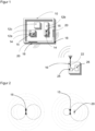
- Figure 1 shows a schematic overview of a device 10, for example an electronic device, with several objects 12a-c or individual components arranged therein, which are at least partially provided with an RFID transponder 14 having an antenna 15.
- An RFID reading device 16 can be arranged outside the device 10 in order to communicate with an RFID transponder 14, in particular to identify an object 12a-c using the RFID transponder 14 attached thereto.
- the read/write range for successful communication between RFID reader 16 and RFID transponder 14 is limited. This range can be limited by shielding effects of walls 18, for example a housing of the device 10, and in the case of a metallic housing, communication may also be completely prevented.
- a resonant structure 20 in the form of a slot structure is provided in at least one wall in order to improve communication. Possible embodiments and the mode of operation of the slot structure are described below with reference to the Figures 2 to 4 explained in more detail.
- the position and size of the resonant structure 20 Depending on the frequency of the RFID communication, there is a respective optimum for the position and size of the resonant structure 20. Since the position of the objects 12a-b and the walls 18 is fixed, an optimal position can only be assumed approximately. The size may also not be ideally implemented due to boundary conditions such as the available space. Nevertheless, the signal attenuation is reduced and communication is improved or even made possible.
- the RFID reading device 16 in turn has an antenna 22, which is designed for the ISM band at around 900 MHz, for example. Instead of the internal antenna 22 shown, an external antenna is also conceivable.
- a transceiver 24 and a control and evaluation unit 26 of the RFID reading device 16 are connected to the antenna 22 in order to evaluate RFID signals received by the antenna 22 or to send information as RFID signals to the RFID transponder 14.
- the control and evaluation unit 26 is preferably connected to a wired or wireless interface (not shown) in order to exchange data, carry out parameterizations and the like.
- the functioning of an RFID reading device for example for the UHF frequency range (ultra high frequency) according to the ISO 18000-6 standard, is known per se and is therefore not explained in more detail.
- Figure 2 shows a schematic representation of the antenna gain of an antenna 15 changed by a resonant structure 20.
- the antenna 15 alone is shown on the left and the antenna with the resonant structure 20 is shown on the right.
- a wire with an extension of approximately half a wavelength of 17.3 cm can be selected as the resonant structure 20 and positioned at a distance of a quarter of the wavelength from the antenna 15.
- a favorable effect also occurs if these specifications are only approximately met and, for example, a wire with a length of 16 cm is used.
- the directivity is significantly improved by the resonant structure 20 when, in the example of the right side of Figure 2 should be read from the right.
- FIGs 3a-f show schematic representations of an antenna 15 of an RFID transponder 14 and an antenna 22 of an RFID reader 16 with different constellations of resonant structures.
- Figure 3a the situation of only the two antennas without additional resonant structure is shown.
- Figure 3b From the perspective of the antenna 22 of the RFID reading device 16, a resonant structure 20 is arranged behind the antenna 15 of the RFID transponder 14, which thus takes on the function of a reflector.
- Figure 3c the order is reversed and the resonant structure 20 is arranged in front of the antenna 15, thus acting as a director.
- Figures 3d-f show constellations in which the resonant structure 20 is supplemented by at least one further resonant structure 20a-b.
- Figure 3d shows an arrangement with two resonant structures 20, 20a in front of the antenna 15, which thus both function as directors.
- Figure 3e shows a resonant structure 20 in front of the antenna 15 and a resonant structure 20a behind the antenna 15 and thus a combination of a director and a reflector.
- Figure 3f is an example of combinations with even more resonant structures to the arrangement of the Figure 3e
- Another resonant element 20b is added as a second director.
- Figure 4 shows a schematic representation of a resonant structure 20 designed as a slot structure, which is introduced into the wall 18.
- the slot structure functions as a slot radiator or slot antenna and is thus also able to improve the reading range or to enable communication into a metal-encased device 10 in the first place.
- the geometric requirements for the slot or the recess in terms of extent and position are the same as already discussed.
- the device 10 is a vehicle, in particular a car.
- Components such as a seat or a control unit are installed as objects 12a-b carrying the RFID transponders 14. These components should still be identifiable by reading the RFID transponders 14 even after the vehicle has been assembled. Due to the installation position, this would be possible according to the state of the art with a RFID reading device 16, which is arranged in front of the vehicle, is not possible.
- a resonant structure 20 can now be attached to a side window or plastic cover as a metal part with the slot structure. It is even simpler to introduce the slot structure into the metallic outer skin, whereby the slot structure can then be filled with plastic, for example, so as not to disturb the overall visual impression of the vehicle.
- the slot structure makes it possible to continue to identify the components of the finished vehicle from outside by reading the RFID transponders 14.
- the device 10 is an electrical appliance, in particular a large electrical appliance such as a flat screen TV, a vacuum cleaner or a washing machine.
- a compact RFID transponder 14 was integrated into the device 10, which is intended to make it possible to identify a component or the entire electrical appliance.
- the size of the transponder would only allow reading at a short distance, such as less than 10 cm.
- identification from the outside should be possible without dismantling a housing.
- a slot structure is introduced into a circuit board above the transponder as a resonant structure 20 or a metal element with the slot structure is arranged there, alternatively the slot structure is introduced into a housing wall, in particular a metallic one. Due to the thus improved radiation characteristics of the RFID transponder 14, identification can now take place from the outside. A marking can also be attached to the housing to show the user from which position of an RFID reading device 16 the reading of the RFID transponder 14 is particularly easy.
Landscapes
- Engineering & Computer Science (AREA)
- Physics & Mathematics (AREA)
- General Physics & Mathematics (AREA)
- Theoretical Computer Science (AREA)
- Health & Medical Sciences (AREA)
- Toxicology (AREA)
- Computer Hardware Design (AREA)
- Electromagnetism (AREA)
- Microelectronics & Electronic Packaging (AREA)
- Artificial Intelligence (AREA)
- Computer Vision & Pattern Recognition (AREA)
- General Health & Medical Sciences (AREA)
- Computer Networks & Wireless Communication (AREA)
- Computer Security & Cryptography (AREA)
- Aerials With Secondary Devices (AREA)
- Near-Field Transmission Systems (AREA)
Abstract
Es wird ein System aus einer Vorrichtung (10) zur Aufnahme mindestens eines Objekts (12a-b) und einem in der Vorrichtung (10) angeordneten Objekt (12a-b) angegeben, wobei an dem Objekt (12a-b) ein RFID-Transponder (14) mit einer Antenne (15) angeordnet ist und wobei die Vorrichtung (10) mindestens eine Wand (18) und mindestens eine zu dem Objekt (12a-b) beabstandete resonante Struktur (20) aufweist. Dabei ist die resonante Struktur (20) als Schlitzstruktur in die Wand (18) eingebracht.
Description
- Die Erfindung betrifft eine Vorrichtung zur Aufnahme mindestens eines Objekts mit einem RFID-Transponder sowie ein Verfahren zum Lesen eines RFID-Transponders auf einem Objekt in einer Vorrichtung nach dem Oberbegriff von Anspruch 1 beziehungsweise 10.
- Eine RFID-Lesevorrichtung regt über ihre Antenne durch elektromagnetische Strahlung in ihrem Lesebereich befindliche RFID-Transponder zur Abstrahlung der gespeicherten Information an, empfängt die entsprechenden Transpondersignale und wertet sie aus. Dazu wird häufig der UHF-Frequenzbereich (Ultrahochfrequenz) verwendet, da es hier in dem Standard ISO 18000-6 einen etablierten Rahmen gibt und zudem Transponder in unterschiedlichen Entfernungen von einigen Millimetern bis hin zu mehreren Metern ausgelesen werden können. UHF-RFID-Transponder sind in sehr kompakten Bauformen verfügbar und können dementsprechend auch an sehr kleinen Objekten angebracht werden.
- Ein Einsatzgebiet von RFID-Transpondern ist eine möglichst lückenlose Dokumentation von Produktionsprozessen beispielsweise zur Qualitätssicherung und Rückverfolgbarkeit. Vielfach besteht der Wunsch, auch nach der Fertigung eines Produktes die einzelnen verwendeten Baugruppen identifizieren zu können. Dabei haben RFID-Transponder den Vorteil, dass eine Identifikation auch im Inneren etwa eines Gehäuses möglich ist, wo optische Erfassungen naturgemäß versagen müssten.
- Die mögliche Kommunikationsreichweite für die drahtlose Aussendung und den Empfang der elektromagnetischen Wellen der RFID-Signale ist dabei begrenzt durch Faktoren wie die Freiraumdämpfung, die unter anderem durch länderspezifische Normen festgelegte maximal zulässige Sendeleistung, die Empfindlichkeit der Empfängerbauteile und den Antennengewinn sowohl der RFID-Lesevorrichtung als auch des RFID-Transponders.
- Unter diesen Faktoren spielt der Antennengewinn des RFID-Transponders eine besonders wichtige Rolle. Dieser wiederum hängt neben der Antennenstruktur vor allem von der Größe der Antenne und damit des RFID-Transponders ab. Gerade für die Identifikation von Baugruppen, die bisweilen selbst sehr klein sind und deren Eigenschaften jedenfalls durch den RFID-Transponder möglichst wenig beeinflusst werden sollen, werden jedoch besonders kleine RFID-Transponder eingesetzt. Deren geringer Antennengewinn führt zu einer geringen Lesereichweite, so dass der RFID-Transponder in einem größeren Gerät oder einer Maschine nicht mehr gelesen werden kann. Ein weiteres Problem stellen metallische Gehäuse dar, die aufgrund ihrer abschirmenden Eigenschaften eine Funkverbindung verhindern oder stark beeinträchtigen.
- Aus der
US 6 320 509 und derUS 6 441 740 sind jeweils Anordnungen bekannt, in denen ein RFID-Transponder mit einem oder mehreren metallischen Reflektoren in Form von geraden oder gekrümmten Flächen versehen wird, um auf diese Weise den Antennengewinn in eine Vorzugsrichtung zu bündeln. Dafür werden aber Reflektorflächen benötigt, die deutlich größer sind als die Transponderstrukturen. - Seit langem sind Yagi-Antennen weit verbreitet, die darauf beruhen, dass die Richtwirkung einer Dipolantenne in eine Richtung gebündelt werden kann, wenn zusätzliche auf die Resonanzfrequenz abgestimmte Stäbe aus leitfähigem Material vor und hinter der Dipolantenne positioniert werden. Das kann dann auf Seiten der RFID-Lesevorrichtung eingesetzt werden, wie etwa in der
US 2009/0174557 A1 beschrieben. Die Strukturen auf Seiten des RFID-Transponders beruhen jedoch nicht zuletzt aus Platzgründen auf anderen Antennenoptimierungen. - In der
WO 00/21030 - Die
US 2008/0303633 A1 offenbart Reflektoren und Direktoren, die zu einem RFID-Transponder beabstandet angeordnet werden, um Yagi-Antennen zu bilden, die eine Lesereichweite verdoppeln können. Das löst aber noch nicht das Problem, ins Innere eines Gerätes hinein lesen zu können, insbesondere durch eine metallische Hülle, und ist auch dann nicht einsetzbar, wenn im Inneren kein Bauraum zur Verfügung steht. - In der
US 2017/0277922 A1 wird ein RFID-Signal mittels Koaxialkabel ins Innere eines Fahrzeugs weitergeleitet. Das bedeutet jedoch einen großen Aufwand und Platzbedarf. - Die
US 7 994 962 B1 offenbart ein Verfahren zum Konzentrieren von RF-Strahlung auf ein Objekt mittels Reflektoren in Dimensionen, die für die Kennzeichnung von Baugruppen nicht brauchbar wären. - Es ist daher Aufgabe der Erfindung, das Lesen von RFID-Transpondern weiter zu verbessern.
- Diese Aufgabe wird durch eine Vorrichtung zur Aufnahme mindestens eines Objekts mit einem RFID-Transponder sowie ein Verfahren zum Lesen eines RFID-Transponders auf einem Objekt in einer Vorrichtung nach Anspruch 1 beziehungsweise 10 gelöst. Die Vorrichtung ist beispielsweise ein elektronisches Gerät, ein Fahrzeug, eine Maschine oder ein Teil davon, insbesondere eine umhüllende beziehungsweise Objekte tragende Konstruktion oder ein Gehäuse. Die Vorrichtung weist wenigstens eine Wand auf, so dass insbesondere bezüglich der Wand ein Innen und ein Außen unterschieden werden können. Das Objekt kann eine Baugruppe oder Komponente davon sein und ist mit einem RFID-Transponder gekennzeichnet, um es mittels einer RFID-Lesevorrichtung zu identifizieren. Der RFID-Transponder weist eine integrierte Antenne auf. Deren effektiver Antennengewinn und damit die Lesereichweite wird durch mindestens eine zu dem Objekt und somit auch dem RFID-Transponder mit dessen Antenne beabstandete resonante Struktur erhöht.
- Die Erfindung geht von dem Grundgedanken aus, die resonante Struktur gemeinsam mit der Wand zu realisieren. Dazu wird sie als Schlitzstruktur in die Wand eingebracht. Liest nun eine RFID-Lesevorrichtung von der dem RFID-Transponder abgewandten Seite der Wand her, so wirkt die Schlitzstruktur effektiv wie eine Verlängerung der Antenne des RFID-Transponders.
- Die Erfindung hat den Vorteil, dass eine Verbesserung der Sende- und Empfangseigenschaften des RFID-Transponders erreicht wird, mit der sich die Lesereichweite vergrößert. Dadurch kann auch mit besonders kleinen oder kompakten RFID-Transpondern verschiedener Bauformen kommuniziert werden, die dafür originär einen zu kleinen Antennengewinn aufweisen, zu weit entfernt wären oder durch Schirmwirkungen beziehungsweise Dämpfungen insbesondere der Wand nicht erfasst würden. Die RFID-Transponder selbst müssen dafür nicht nachträglich modifiziert werden. Das Anbringen der Schlitzstrukturerfordert nur wenig Aufwand und keinerlei zusätzliche Materialkosten.
- Die Vorrichtung ist bevorzugt als Gehäuse oder Verkleidung ausgebildet. Die Wand schließt das Gehäuse vorzugsweise in einer Richtung ab. Das Gehäuse kann das Au-ßengehäuse eines elektronischen Geräts sein, aber auch ein inneres Gehäuse einer Komponente oder eines Moduls. Somit sind mehrere Teilgehäuse ebenso denkbar wie mehrere Objekte innerhalb eines Gehäuses, von denen eines, mehrere oder alle Objekte mit einem oder mehreren RFID-Transpondern gekennzeichnet sein können.
- Die Wand ist vorzugsweise eine metallische Wand. Vorzugsweise ist ein Gehäuse der Vorrichtung insgesamt aus Metall. Ein Beispiel ist die metallische Außenhaut eines Fahrzeugs. Durch eine metallische Wand oder Umhüllung könnte wegen der Schirmwirkung nach dem Stand der Technik gar nichts gelesen werden. Die Schlitzstruktur macht die Wand nicht nur effektiv transparent für das RFID-Signal, sondern erhöht dabei auch noch die Lesereichweite. In eine nicht metallische Wand kann beispielsweise ein Metallelement mit der Schlitzstruktur eingebracht werden.
- Die resonante Struktur ist vorzugsweise auf eine Wellenlänge des RFID-Transponders abgestimmt. Insbesondere kann eine Strukturgröße der halben Wellenlänge des RFID-Transponders gewählt werden. Die notwendige Größe ist damit einfach abschätzbar, und die Schlitzstruktur kann recht klein bleiben. Bei einer RFID-Frequenz von 866,5 MHz beispielsweise wären es etwa 17,3cm. Diese Größe muss nicht exakt eingehalten werden, die Resonanz verschlechtert sich mit Abweichungen, aber es wird weiterhin eine signifikante, wenn auch nicht die höchstmögliche Reichweitenerhöhung erzielt.
- Die resonante Struktur ist vorzugsweise in einem auf eine Wellenlänge des RFID-Transponders abgestimmten Abstand zu dem Objekt angeordnet. Insbesondere beträgt der Abstand ein Viertel der Wellenlänge des RFID-Transponders. Da sich die Anordnung des Objekts bezüglich der Wand üblicherweise nicht an den Bedürfnissen der RFID-Lesung ausrichtet, besteht oftmals nur die Wahl, welche Wand in geeignetem Abstand zu dem Objekt mit der Schlitzstruktur versehen werden sollte. Der optimale Abstand wird dann in der Regel nur näherungsweise erreicht. Wie schon im Falle der Größe der resonanten Struktur führt aber bereits ein ungefähr eingehaltener idealer Abstand schon zu einer Reichweitenerhöhung.
- Das Objekt weist bevorzugt mindestens eine zweite resonante Struktur auf. Die zweite resonante Struktur wirkt mit der Schlitzstruktur zusammen, um die Richtwirkung beziehungsweise Reichweitenerhöhung zusätzlich zu verbessern. Für die zweite resonante Struktur sind verschiedene Bauformen vorstellbar, wie Draht, eine elektrische Leiterbahn auf einer Platine, eine metallisierte Folie mit Klebeschicht, metallischer Druck oder eine Integration von Metallpartikeln in Kunststoff, insbesondere mittels 3D-Druck. Sofern eine weitere Wand in geeigneter Position zur Verfügung steht oder hinzugefügt wird, kann die zweite resonante Struktur ebenfalls eine Schlitzstruktur sein.
- Die zweite resonante Struktur ist vorzugsweise als Direktor zwischen der Schlitzstruktur und dem Objekt angeordnet. Die zweite resonante Struktur liegt dann im Ausbreitungsweg des RFID-Signals zwischen RFID-Transponder und RFID-Lesevorrichtung. Alternativ ist die zweite resonante Struktur als Reflektor in einer Verlängerung der Verbindung von Schlitzstruktur und Objekt und damit gleichsam hinter dem eigentlichen Ausbreitungsweg angeordnet. Es ist denkbar, eine dritte resonante Struktur oder weitere resonante Strukturen als Direktoren und/oder Resonatoren vorzusehen.
- Das System weist bevorzugt eine RFID-Lesevorrichtung auf, um eine Information des RFID-Transponders auszulesen. Die RFID-Lesevorrichtung umfasst vorzugsweise mindestens eine eigene interne oder externe Antenne, einen mit der Antenne verbundenen Transceiver sowie eine mit dem Transceiver verbundene RFID-Steuer- und Auswertungseinheit. Die Antenne wird von der RFID-Lesevorrichtung zum Senden von RFID-Signalen an den RFID-Transponder und/oder zum Empfangen von RFID-Signalen von dem RFID-Transponder verwendet. Als Transceiver wird hier jede Kombination eines Senders und Empfängers bezeichnet. Die RFID-Steuer- und Auswertungseinheit, die mindestens einen digitalen Rechenbaustein aufweist, wie einen Mikroprozessor, ein FPGA (Field Programmable Gate Array), einen ASIC (Application Specific Integrated Circuit) oder dergleichen, ist für das Eincodieren einer RFID-Information in die RFID-Signale und/oder zum Auslesen einer RFID-Information aus den RFID-Signalen ausgebildet. Transceiver und RFID-Steuer- und Auswertungseinheit können einen gemeinsamen Rechenbaustein bilden oder jedenfalls teilweise einen Rechenbaustein gemeinsam nutzen. Dank der Schlitzstruktur ist die Lesereichweite erhöht, aus der die RFID-Lesevorrichtung den RIFD-Transponder lesen kann.
- Das erfindungsgemäße Verfahren kann auf ähnliche Weise weitergebildet werden und zeigt dabei ähnliche Vorteile. Derartige vorteilhafte Merkmale sind beispielhaft, aber nicht abschließend in den sich an die unabhängigen Ansprüche anschließenden Unteransprüchen beschrieben.
- Die Erfindung wird nachstehend auch hinsichtlich weiterer Merkmale und Vorteile beispielhaft anhand von Ausführungsformen und unter Bezug auf die beigefügte Zeichnung näher erläutert. Die Abbildungen der Zeichnung zeigen in:
- Fig. 1
- eine schematische Übersichtsdarstellung einer Vorrichtung mit mehreren darin angeordneten Objekten oder Komponenten, die zumindest teilweise mit einem RFID-Transponder versehen sind, sowie mit einer RFID-Lesevorrichtung;
- Fig. 2
- eine schematische Darstellung des durch eine resonante Struktur veränderten Antennengewinns einer Antenne;
- Fig. 3a-f
- schematische Darstellungen der Antennen eines RFID-Transponders und einer RFID-Lesevorrichtung mit verschiedenen Konstellationen von resonanten Strukturen; und
- Fig. 4
- eine schematische Darstellung einer als Schlitzstruktur ausgebildeten resonanten Struktur.
-
Figur 1 zeigt eine schematische Übersichtsdarstellung einer Vorrichtung 10, beispielsweise ein elektronisches Gerät, mit mehreren darin angeordneten Objekten 12a-c oder Einzelkomponenten, die zumindest teilweise mit einem RFID-Transponder 14 versehen sind, der eine Antenne 15 aufweist. Eine RFID-Lesevorrichtung 16 kann außerhalb der Vorrichtung 10 angeordnet werden, um mit einem RFID-Transponder 14 zu kommunizieren, insbesondere ein Objekt 12a-c anhand des daran angebrachten RFID-Transponders 14 zu identifizieren. - Gerade bei kleinen RFID-Transpondern 14 ist die Lese-/Schreibreichweite für eine erfolgreiche Kommunikation zwischen RFID-Lesevorrichtung 16 und RFID-Transponder 14 begrenzt. Diese Reichweite kann durch Schirmeffekte von Wänden 18 beispielsweise eines Gehäuses der Vorrichtung 10 noch verschlechtert werden, und im Falle eines metallischen Gehäuses kann eine Kommunikation auch vollständig verhindert werden.
- Deshalb ist in mindestens einer Wand eine resonante Struktur 20 in Form einer Schlitzstruktur vorgesehen, um die Kommunikation zu verbessern. Mögliche Ausgestaltungen und die Wirkungsweise der Schlitzstruktur werden im Anschluss unter Bezugnahme auf die
Figuren 2 bis 4 noch näher erläutert. Es gibt in Abhängigkeit von der Frequenz der RFID-Kommunikation ein jeweiliges Optimum für die Position und Größe der resonanten Struktur 20. Da die Position der Objekte 12a-b und der Wände 18 festliegt, kann eine optimale Position unter Umständen nur näherungsweise eingenommen werden. Auch die Größe ist womöglich durch Randbedingungen wie den verfügbaren Raum nicht ideal umsetzbar. Trotzdem wird die Signaldämpfung reduziert und die Kommunikation verbessert oder sogar erst ermöglicht. - Die RFID-Lesevorrichtung 16 weist ihrerseits eine Antenne 22 auf, die beispielsweise für das ISM-Band bei etwa 900 MHz ausgelegt ist. Anstelle der dargestellten internen Antenne 22 ist auch eine externe Antenne denkbar. An die Antenne 22 ist ein Transceiver 24 und daran eine Steuer- und Auswertungseinheit 26 der RFID-Lesevorrichtung 16 angeschlossen, um mittels der Antenne 22 empfangene RFID-Signale auszuwerten oder Informationen als RFID-Signale an den RFID-Transponder 14 zu senden. Die Steuer- und Auswertungseinheit 26 ist vorzugsweise mit einer nicht gezeigten, drahtgebundenen oder drahtlosen Schnittstelle verbunden, um Daten auszutauschen, Parametrierungen vorzunehmen und dergleichen. Die Funktionsweise einer RFID-Lesevorrichtung beispielsweise für den UHF-Frequenzbereich (Ultrahochfrequenz) nach dem Standard ISO 18000-6 ist an sich bekannt und wird deshalb nicht näher erläutert.
-
Figur 2 zeigt eine schematische Darstellung des durch eine resonante Struktur 20 veränderten Antennengewinns einer Antenne 15. Dabei ist zum Vergleich auf der linken Seite die Antenne 15 allein und auf der rechten Seite die Antenne mit der resonanten Struktur 20 dargestellt. Beispielsweise kann für einen RFID-Transponder 14 im UHF-Frequenzband bei 88,5 MHz ein Draht mit der Ausdehnung ungefähr einer halben Wellenlänge von 17,3 cm als resonante Struktur 20 ausgewählt werden und im Abstand eines Viertels der Wellenlänge zu der Antenne 15 positioniert werden. Wie schon erwähnt, tritt ein günstiger Effekt auch dann ein, wenn diese Vorgaben nur näherungsweise eingehalten werden und beispielsweise ein Draht der Länge 16 cm verwendet wird. Die Richtwirkung wird durch die resonante Struktur 20 deutlich verbessert, wenn im Beispiel der rechten Seite vonFigur 2 von rechts her gelesen werden soll. - Die
Figuren 3a-f zeigen jeweils schematische Darstellungen einer Antenne 15 eines RFID-Transponders 14 und einer Antenne 22 einer RFID-Lesevorrichtung 16 mit verschiedenen Konstellationen von resonanten Strukturen. Zunächst ist zum Vergleich inFigur 3a die Situation nur der beiden Antennen ohne zusätzliche resonante Struktur dargestellt. InFigur 3b ist, aus Sicht der Antenne 22 der RFID-Lesevorrichtung 16, eine resonante Struktur20 hinter der Antenne 15 des RFID-Transponders 14 angeordnet, die somit die Funktion eines Reflektors einnimmt. InFigur 3c ist die Reihenfolge umgekehrt und die resonante Struktur20 vor der Antenne 15 angeordnet, fungiert somit als Direktor. - Die
Figuren 3d-f zeigen Konstellationen, in denen die resonante Struktur 20 um mindestens eine weitere resonante Struktur 20a-b ergänzt ist. Dabei sind prinzipiell auch noch mehr resonante Strukturen und zusätzliche damit realisierte Kombinationen von Reflektoren und Direktoren möglich.Figur 3d zeigt eine Anordnung mit zwei resonanten Strukturen 20, 20a vor der Antenne 15, die somit beide als Direktoren fungieren.Figur 3e zeigt je eine resonante Struktur 20 vor der Antenne 15 und eine resonante Struktur 20a hinter der Antenne 15 und somit eine Kombination eines Direktors und eines Reflektors. InFigur 3f ist als ein Beispiel für Kombinationen mit noch mehr resonanten Strukturen zu der Anordnung derFigur 3e noch ein weiteres resonantes Element 20b als zweiter Direktor ergänzt. -
Figur 4 zeigt eine schematische Darstellung einer als Schlitzstruktur ausgebildeten resonanten Struktur 20, die in die Wand 18 eingebracht ist. Die Schlitzstruktur fungiert als Schlitzstrahler oder Schlitzantenne und ist damit ebenfalls in der Lage, die Lesereichweite zu verbessern beziehungsweise eine Kommunikation in eine metallisch umhüllte Vorrichtung 10 hinein überhaupt erst zu ermöglichen. Die geometrischen Anforderungen an den Schlitz oder die Aussparung hinsichtlich Ausdehnung und Position sind die gleichen wie bereits diskutiert. - Ein einem Anwendungsbeispiel ist die Vorrichtung 10 ein Fahrzeug, insbesondere ein PKW. Als die RFID-Transponder 14 tragende Objekte 12a-b sind darin Komponenten wie ein Sitz oder ein Steuergerät verbaut. Diese Komponenten sollen auch nach abgeschlossener Fahrzeugmontage noch durch Lesen der RFID-Transponder 14 identifizierbar sein. Aufgrund der Einbaulage wäre das nach dem Stand der Technik mit einer RFID-Lesevorrichtung 16, die vor dem Fahrzeug angeordnet wird, nicht möglich. In einer Ausführungsform der Erfindung kann nun an einer Seitenscheibe oder Kunststoffabdeckung eine resonante Struktur 20 als ein Metallteil mit der Schlitzstruktur angebracht werden. Noch einfacher ist, die Schlitzstruktur in die metallische Außenhaut einzubringen, wobei die Schlitzstruktur dann beispielsweise mit Kunststoff gefüllt sein kann, um den optischen Gesamteindruck des Fahrzeugs nicht zu stören. Die Schlitzstruktur ermöglicht es, die Komponenten des fertigen Fahrzeugs weiterhin von außerhalb durch Lesen der RFID-Transponder 14 zu identifizieren.
- In einem anderen Anwendungsbeispiel ist die Vorrichtung 10 ein Elektrogerät, insbesondere ein großes Elektrogerät wie ein Flachbildfernseher, ein Staubsauger oder eine Waschmaschine. Innerhalb der Produktionskette wurde in die Vorrichtung 10 ein kompakter RFID-Transponder 14 integriert, der es ermöglichen soll, eine Komponente oder auch das gesamte Elektrogerät zu identifizieren. Die Transpondergröße würde gemäß Stand der Technik ein Lesen nur auf geringe Entfernung wie beispielsweise weniger als 10 cm erlauben. Insbesondere im Fall einer Reparatur oder Wartung soll aber die Identifikation von außen ohne Demontage eines Gehäuses möglich sein. Deshalb wird nun in einer Ausführungsform der Erfindung oberhalb des Transponders in eine Platine eine Schlitzstruktur als resonante Struktur 20 eingebracht oder dort ein Metallelement mit der Schlitzstruktur angeordnet, alternativ in eine insbesondere metallische Gehäusewand die Schlitzstruktur eingebracht. Durch die somit verbesserte Abstrahlungscharakteristik des RFID-Transponders 14 kann nun die Identifikation von außen erfolgen. Auf dem Gehäuse kann zudem eine Kennzeichnung angebracht werden, um dem Anwender anzuzeigen, von welcher Position einer RFID-Lesevorrichtung 16 das Lesen des RFID-Transponders 14 besonders gut möglich ist.
Claims (10)
- System aus einer Vorrichtung (10) zur Aufnahme mindestens eines Objekts (12a-b) und einem in der Vorrichtung (10) angeordneten Objekt (12a-b), wobei an dem Objekt (12a-b) ein RFID-Transponder (14) mit einer Antenne (15) angeordnet ist und wobei die Vorrichtung (10) mindestens eine Wand (18) und mindestens eine zu dem Objekt (12a-b) beabstandete resonante Struktur (20) aufweist,
dadurch gekennzeichnet,
dass die resonante Struktur (20) als Schlitzstruktur in die Wand (18) eingebracht ist. - System nach Anspruch 1,
wobei die Vorrichtung (10) als Gehäuse oder Verkleidung ausgebildet ist. - System nach Anspruch 1 oder 2,
wobei die Wand (18) eine metallische Wand ist. - System nach einem der vorhergehenden Ansprüche,
wobei die resonante Struktur (20) auf eine Wellenlänge des RFID-Transponders (14) abgestimmt ist, insbesondere eine Strukturgröße der halben Wellenlänge des RFID-Transponders (14) aufweist. - System nach einem der vorhergehenden Ansprüche,
wobei die resonante Struktur (20) in einem auf eine Wellenlänge des RFID-Transponders (14) abgestimmten Abstand zu dem Objekt (12a-b) angeordnet ist, insbesondere im Abstand eines Viertels der Wellenlänge des RFID-Transponders (14). - System nach einem der vorhergehenden Ansprüche,
wobei das Objekt (12a-b) mindestens eine zweite resonante Struktur (20a-b) aufweist. - System nach einem der vorhergehenden Ansprüche,
wobei die zweite resonante Struktur (20a-b) als Direktor zwischen der Schlitzstruktur und dem Objekt (12a-b) angeordnet ist. - System nach einem der Ansprüche 1 bis 6,
wobei die zweite resonante Struktur (20a-b) als Reflektor in einer Verlängerung der Verbindung von Schlitzstruktur und Objekt (12a-b) angeordnet ist. - System nach einem der vorhergehenden Ansprüche,
das eine RFID-Lesevorrichtung (16) aufweist, um eine Information des RFID-Transponders (14) auszulesen. - Verfahren zum Lesen eines RFID-Transponders (14) auf einem Objekt (12a-b) in einer Vorrichtung (10 ) zur Aufnahme des Objekts (12a-b) mit mindestens einer Wand (18), wobei mindestens eine resonante Struktur (20) in einem Abstand zu dem Objekt (12a-b) angeordnet wird,
dadurch gekennzeichnet,
dass die resonante Struktur (20) als Schlitzstruktur in die Wand (18) eingebracht ist.
Applications Claiming Priority (1)
| Application Number | Priority Date | Filing Date | Title |
|---|---|---|---|
| DE102023117578.5A DE102023117578A1 (de) | 2023-07-04 | 2023-07-04 | Lesen eines RFID-Transponders auf einem Objekt in einer Vorrichtung |
Publications (1)
| Publication Number | Publication Date |
|---|---|
| EP4488876A1 true EP4488876A1 (de) | 2025-01-08 |
Family
ID=91469854
Family Applications (1)
| Application Number | Title | Priority Date | Filing Date |
|---|---|---|---|
| EP24180960.7A Withdrawn EP4488876A1 (de) | 2023-07-04 | 2024-06-10 | Lesen eines rfid-transponders auf einem objekt in einer vorrichtung |
Country Status (4)
| Country | Link |
|---|---|
| US (1) | US12554959B2 (de) |
| EP (1) | EP4488876A1 (de) |
| CN (1) | CN119272780A (de) |
| DE (1) | DE102023117578A1 (de) |
Citations (14)
| Publication number | Priority date | Publication date | Assignee | Title |
|---|---|---|---|---|
| US2518371A (en) * | 1946-03-22 | 1950-08-08 | Csf | Method for the direct modulation of an ultra-short wave transmitter |
| WO2000021030A1 (en) | 1998-10-06 | 2000-04-13 | Intermec Ip Corp. | Rfid transponder having improved rf characteristics |
| US6320509B1 (en) | 1998-03-16 | 2001-11-20 | Intermec Ip Corp. | Radio frequency identification transponder having a high gain antenna configuration |
| US6441740B1 (en) | 1998-02-27 | 2002-08-27 | Intermec Ip Corp. | Radio frequency identification transponder having a reflector |
| US20020167450A1 (en) * | 1999-11-18 | 2002-11-14 | Siemens Ag | Mobile data carrier including a transponder having a surface wave component and a slot antenna |
| US20080303633A1 (en) | 2007-06-07 | 2008-12-11 | The Hong Kong University Of Science And Technology | High gain rfid tag antennas |
| US20090174557A1 (en) | 2008-01-03 | 2009-07-09 | Intermec Ip Corp. | Compact flexible high gain antenna for handheld rfid reader |
| US7994962B1 (en) | 2007-07-17 | 2011-08-09 | Drosera Ltd. | Apparatus and method for concentrating electromagnetic energy on a remotely-located object |
| US20130313328A1 (en) * | 2012-05-25 | 2013-11-28 | Omni-Id Cayman Limited | Shielded Cavity Backed Slot Decoupled RFID TAGS |
| EP2677475A1 (de) * | 2012-06-22 | 2013-12-25 | Join Yiuh Industry Co., Ltd. | Verfahren zur Herstellung eines metallischen Langbereichs-Funkfrequenzidentifizierungsprodukts, und Struktur davon |
| US20170277922A1 (en) | 2016-03-28 | 2017-09-28 | Tai-Hwa Liu | Mobile wireless antenna system for rfid application |
| US20170293832A1 (en) * | 2017-06-27 | 2017-10-12 | Daniel Pai | License plate radio electronic identifier |
| US20170344772A1 (en) * | 2016-05-31 | 2017-11-30 | Sick Ag | Rfid reading apparatus for shelf occupancy detection |
| US20190103682A1 (en) * | 2017-09-30 | 2019-04-04 | Intel IP Corporation | Compact radio frequency (rf) communication modules with endfire and broadside antennas |
Family Cites Families (5)
| Publication number | Priority date | Publication date | Assignee | Title |
|---|---|---|---|---|
| US6703935B1 (en) * | 2001-05-14 | 2004-03-09 | Amerasia International Technology, Inc. | Antenna arrangement for RFID smart tags |
| US20110068987A1 (en) * | 2009-08-05 | 2011-03-24 | New Jersey Microsystems. Inc | Multiband RFID tag |
| US8439272B2 (en) * | 2010-11-15 | 2013-05-14 | Neoid Limited | Resonant circuit structure and RF tag having same |
| US10566962B2 (en) | 2017-10-02 | 2020-02-18 | Cirrus Logic, Inc. | Pulse-width modulation |
| US20240005122A1 (en) * | 2022-06-29 | 2024-01-04 | Nxp B.V. | Radio frequency identification tag with antenna and passive reflector |
-
2023
- 2023-07-04 DE DE102023117578.5A patent/DE102023117578A1/de active Pending
-
2024
- 2024-06-10 EP EP24180960.7A patent/EP4488876A1/de not_active Withdrawn
- 2024-06-21 CN CN202410812168.6A patent/CN119272780A/zh active Pending
- 2024-07-03 US US18/763,404 patent/US12554959B2/en active Active
Patent Citations (14)
| Publication number | Priority date | Publication date | Assignee | Title |
|---|---|---|---|---|
| US2518371A (en) * | 1946-03-22 | 1950-08-08 | Csf | Method for the direct modulation of an ultra-short wave transmitter |
| US6441740B1 (en) | 1998-02-27 | 2002-08-27 | Intermec Ip Corp. | Radio frequency identification transponder having a reflector |
| US6320509B1 (en) | 1998-03-16 | 2001-11-20 | Intermec Ip Corp. | Radio frequency identification transponder having a high gain antenna configuration |
| WO2000021030A1 (en) | 1998-10-06 | 2000-04-13 | Intermec Ip Corp. | Rfid transponder having improved rf characteristics |
| US20020167450A1 (en) * | 1999-11-18 | 2002-11-14 | Siemens Ag | Mobile data carrier including a transponder having a surface wave component and a slot antenna |
| US20080303633A1 (en) | 2007-06-07 | 2008-12-11 | The Hong Kong University Of Science And Technology | High gain rfid tag antennas |
| US7994962B1 (en) | 2007-07-17 | 2011-08-09 | Drosera Ltd. | Apparatus and method for concentrating electromagnetic energy on a remotely-located object |
| US20090174557A1 (en) | 2008-01-03 | 2009-07-09 | Intermec Ip Corp. | Compact flexible high gain antenna for handheld rfid reader |
| US20130313328A1 (en) * | 2012-05-25 | 2013-11-28 | Omni-Id Cayman Limited | Shielded Cavity Backed Slot Decoupled RFID TAGS |
| EP2677475A1 (de) * | 2012-06-22 | 2013-12-25 | Join Yiuh Industry Co., Ltd. | Verfahren zur Herstellung eines metallischen Langbereichs-Funkfrequenzidentifizierungsprodukts, und Struktur davon |
| US20170277922A1 (en) | 2016-03-28 | 2017-09-28 | Tai-Hwa Liu | Mobile wireless antenna system for rfid application |
| US20170344772A1 (en) * | 2016-05-31 | 2017-11-30 | Sick Ag | Rfid reading apparatus for shelf occupancy detection |
| US20170293832A1 (en) * | 2017-06-27 | 2017-10-12 | Daniel Pai | License plate radio electronic identifier |
| US20190103682A1 (en) * | 2017-09-30 | 2019-04-04 | Intel IP Corporation | Compact radio frequency (rf) communication modules with endfire and broadside antennas |
Also Published As
| Publication number | Publication date |
|---|---|
| US20250013849A1 (en) | 2025-01-09 |
| CN119272780A (zh) | 2025-01-07 |
| DE102023117578A1 (de) | 2025-01-09 |
| US12554959B2 (en) | 2026-02-17 |
Similar Documents
| Publication | Publication Date | Title |
|---|---|---|
| EP2811575B1 (de) | Antenne | |
| DE10192529B4 (de) | Antennensystem | |
| EP2490150B1 (de) | RFID-Lesetunnel und Verfahren zum Auslesen von RFID-Transpondern | |
| EP1990755B1 (de) | Verfahren zum Betrieb eins RFID-Tags mit genauer Lokalisierung | |
| EP1336158A1 (de) | Kontaktloser datenträger | |
| DE202010008162U1 (de) | RFID-Lesevorrichtung | |
| WO2018050420A1 (de) | Antennenanordnung | |
| DE102014118391A1 (de) | Vorrichtung zur Übertragung von Signalen aus einem Metall-Gehäuse | |
| WO2004017093A1 (de) | Sensor zum aussenden und empfangen von elektromagnetischen signalen | |
| EP0993748A1 (de) | Kommunikationseinsteckkarte | |
| DE102007029083A1 (de) | Kartendatenträger mit Detektierplättchen | |
| EP3669300B1 (de) | Vorrichtung und verfahren zum senden und empfangen von daten eines passiven rfid-tags | |
| DE102018100845A1 (de) | Füllstandmessgerät | |
| DE102008018776A1 (de) | Lager, insbesondere Wälz- oder Gleitlager oder Linearführung, mit einem Transponder | |
| DE202023103690U1 (de) | Lesen eines RFID-Transponders auf einem Objekt in einer Vorrichtung | |
| DE102023117578A1 (de) | Lesen eines RFID-Transponders auf einem Objekt in einer Vorrichtung | |
| WO2007131879A1 (de) | Testvorrichtung mit hf-/uhf-dualbandantenne zum testen von rfid-transpondern in einem fertigungsgerät | |
| DE102018122423A1 (de) | Vorrichtung zur Übertragung von Signalen aus einem zumindest teilweise metallischen Gehäuse | |
| EP2790269B1 (de) | Antenne | |
| DE202008015803U1 (de) | Computersystem mit Antennenanordnung | |
| DE102012000762A1 (de) | Antennenabdeckung | |
| EP1936740B1 (de) | System und Verfahren zur Messung einer Bewegungsinformation nach dem Doppler-Prinzip | |
| DE102023124739B3 (de) | Vorrichtung zum Beschreiben und/oder Auslesen von RFID-Tags | |
| EP3808577B1 (de) | Reifen | |
| DE102015214172B4 (de) | Vorrichtung zur Objekterfassung |
Legal Events
| Date | Code | Title | Description |
|---|---|---|---|
| PUAI | Public reference made under article 153(3) epc to a published international application that has entered the european phase |
Free format text: ORIGINAL CODE: 0009012 |
|
| STAA | Information on the status of an ep patent application or granted ep patent |
Free format text: STATUS: THE APPLICATION HAS BEEN PUBLISHED |
|
| AK | Designated contracting states |
Kind code of ref document: A1 Designated state(s): AL AT BE BG CH CY CZ DE DK EE ES FI FR GB GR HR HU IE IS IT LI LT LU LV MC ME MK MT NL NO PL PT RO RS SE SI SK SM TR |
|
| STAA | Information on the status of an ep patent application or granted ep patent |
Free format text: STATUS: THE APPLICATION IS DEEMED TO BE WITHDRAWN |
|
| 18D | Application deemed to be withdrawn |
Effective date: 20250709 |