EP4488730A1 - Multicore fiber connecting device and multicore fiber connecting method - Google Patents
Multicore fiber connecting device and multicore fiber connecting method Download PDFInfo
- Publication number
- EP4488730A1 EP4488730A1 EP22929691.8A EP22929691A EP4488730A1 EP 4488730 A1 EP4488730 A1 EP 4488730A1 EP 22929691 A EP22929691 A EP 22929691A EP 4488730 A1 EP4488730 A1 EP 4488730A1
- Authority
- EP
- European Patent Office
- Prior art keywords
- multicore fiber
- fiber
- optical
- testing light
- multicore
- Prior art date
- Legal status (The legal status is an assumption and is not a legal conclusion. Google has not performed a legal analysis and makes no representation as to the accuracy of the status listed.)
- Pending
Links
Images




Classifications
-
- G—PHYSICS
- G02—OPTICS
- G02B—OPTICAL ELEMENTS, SYSTEMS OR APPARATUS
- G02B6/00—Light guides; Structural details of arrangements comprising light guides and other optical elements, e.g. couplings
- G02B6/24—Coupling light guides
- G02B6/255—Splicing of light guides, e.g. by fusion or bonding
- G02B6/2555—Alignment or adjustment devices for aligning prior to splicing
-
- G—PHYSICS
- G02—OPTICS
- G02B—OPTICAL ELEMENTS, SYSTEMS OR APPARATUS
- G02B6/00—Light guides; Structural details of arrangements comprising light guides and other optical elements, e.g. couplings
- G02B6/02—Optical fibres with cladding with or without a coating
- G02B6/02042—Multicore optical fibres
Definitions
- the present invention relates to a multicore fiber connecting device and a multicore fiber connecting method, and, particularly, relates to a multicore fiber connecting device and a multicore fiber connecting method that are used in a multicore fiber optical transmission system.
- a spatial multiplexing technique being a multiplexing technique of a dimension differing from a conventional multiplexing technique.
- a spatial multiplexing technique there are a multicore technique that increases the number of cores per optical fiber, and a multi-mode technique that increases the number of propagation modes.
- Each of the number of cores and the number of modes used in current optical fiber communication is one.
- multicore fibers A 1 and A 2 are opposed with axis alignment ends a 3 and a 4 thereof close to each other.
- a controller S 0 controls an attraction mechanism of an axis alignment device
- a controller S 1 controls a rotation mechanism of the axis alignment device.
- wavelengths of two optical signals leading to the controllers S 0 and S 1 are caused to differ from each other, a wavelength of one optical signal is set to ⁇ 0 , and a wavelength of the other optical signal is set to ⁇ 1 .
- one optical signal ⁇ 0 is passed through each of center cores of the both multicore fibers A 1 and A 2 , and the other optical signal ⁇ 1 is passed through each peripheral core. Then, such axis alignment end movement adjustment in X and Y directions and axis alignment end rotational adjustment in a ⁇ direction that optical power becomes maximum in each of the controllers S 0 and S 1 are performed. As a result, it is said that each of the controllers S 0 and S 1 acquires a maximum value of optical power only by a predetermined signal.
- An object of the present invention is to provide a multicore fiber connecting device and a multicore fiber connecting method that solve a problem, being the above-described problem, that, when a multicore fiber is connected and used, intensity of an optical signal guided through the multicore fiber differs for each core.
- a multicore fiber connecting device includes a fiber position adjusting means for adjusting spatial positions of a first multicore fiber and a second multicore fiber connected to the first multicore fiber, a first optical connecting means for introducing testing light of a different wavelength for each core, to each of the cores of the first multicore fiber, an optical spectrum information generating means for generating optical spectrum information of the testing light after the testing light has been guided through the first multicore fiber and the second multicore fiber, and a control means for controlling the fiber position adjusting means by use of the optical spectrum information.
- a multicore fiber connecting method includes introducing testing light of a different wavelength for each core, to each of the cores of a first multicore fiber, generating optical spectrum information of the testing light after the testing light has been guided through the first multicore fiber, and a second multicore fiber connected to the first multicore fiber, and adjusting spatial positions of the first multicore fiber and the second multicore fiber by use of the optical spectrum information.
- a multicore fiber connecting device and a multicore fiber connecting method according to the present invention can uniform, when a multicore fiber is connected and used, intensity for each core of an optical signal guided through the multicore fiber.
- Fig. 1 is a block diagram illustrating a configuration of a multicore fiber connecting device 100 according to a first example embodiment of the present invention.
- the multicore fiber connecting device 100 includes a fiber position adjusting unit (fiber position adjusting means) 110, a first optical connecting unit (first optical connecting means) 120, an optical spectrum information generating unit (optical spectrum information generating means) 130, and a control unit (control means) 140.
- the fiber position adjusting unit 110 adjusts spatial positions of a first multicore fiber 10, and a second multicore fiber 20 connected to the first multicore fiber 10.
- the first optical connecting unit 120 introducing testing light of a different wavelength for each core, to each of the cores of the first multicore fiber 10.
- the optical spectrum information generating unit 130 generates optical spectrum information of the testing light after the testing light has been guided through the first multicore fiber 10 and the second multicore fiber 20. Then, the control unit 140 controls the fiber position adjusting unit 110 by use of the optical spectrum information.
- the multicore fiber connecting device 100 is configured to introduce, to a multicore fiber, testing light of a different wavelength for each core, and adjust a spatial position of the multicore fiber by use of optical spectrum information of the testing light after the testing light has been guided through the multicore fiber.
- the spatial position of the multicore fiber can be adjusted in such a way that a connection loss for each core becomes uniform. Therefore, the multicore fiber connecting device 100 according to the present example embodiment can uniform, when a multicore fiber is connected and used, intensity for each core of an optical signal guided through the multicore fiber.
- the fiber position adjusting unit 110 adjusts, in relation to each of positions of the first multicore fiber 10 and the second multicore fiber 20, each of an in-plane position (x-direction and y-direction in the figure), an axial position (z-direction), and a rotation amount ( ⁇ -direction and ⁇ -direction).
- Fig. 2 illustrates, as an example, a case where each of the first multicore fiber 10 and the second multicore fiber 20 includes four cores (C11 to C14 and C21 to C24).
- the first optical connecting unit 120 can be configured to include a fan-in fan-out (FIFO) unit (fan-in fan-out means).
- FIFO fan-in fan-out means
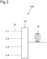
- Fig. 3 illustrates one example of a configuration of the first optical connecting unit 120.
- the fan-in fan-out unit 121 connects each core of the first multicore fiber 10 to each of first single-core fibers 31 through which each of beams of testing light of different wavelengths ( ⁇ 1 to ⁇ 4 in the example of Fig. 3 ) is guided.
- the first single-core fiber 31 is typically a single mode fiber (SMF).
- SMF single mode fiber
- As the fan-in fan-out (FIFO) unit 121 a fine bundle type FIFO or a melt drawing type FIFO can be used. Alternatively, a spatial optical FIFO or a planar optical waveguide type FIFO may be used.
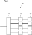
- Fig. 4 illustrates one example of a configuration of the optical spectrum information generating unit 130.
- the optical spectrum information generating unit 130 can be configured to include an optical coupler 131, an optical bandpass filter 132, and an optical power meter 133.
- Fig. 4 illustrates a configuration including four optical bandpass filters 132 associated with different wavelengths ( ⁇ 1 to ⁇ 4 in the example of Fig. 4 ) of testing light, the present invention is not limited to thereto, and a configuration including a wavelength turnable optical bandpass filter may be adopted.
- Fig. 5 illustrates one example of optical spectrum information of testing light generated by the optical spectrum information generating unit 130.
- the control unit 140 can be configured to control the fiber position adjusting unit 110 in such a way that a difference in light intensity for each of the different wavelengths ( ⁇ 1 to ⁇ 4 in the example of Fig. 5 ) of the testing light is reduced.
- the control unit 140 adjusts positions (x-direction, y-direction, and z-direction) and rotation ( ⁇ -direction, ⁇ -direction) of the first multicore fiber 10 and the second multicore fiber 20, and controls in such a way that a difference in light intensity for each of the different wavelengths of the testing light is reduced.
- a central processing unit (CPU) or the like can be used as the control unit 140.
- the multicore fiber connecting device 100 can be configured to further include an end face fusing portion (end face fusing means).
- the end face fusing portion melts and connects an end face of the first multicore fiber 10 and the end face of the second multicore fiber 20.
- the fiber position adjusting unit 110 and the end face fusing portion constitute an optical fiber fusion splicer.
- the optical fiber fusion splicer is a device that melts an optical fiber end with heat generated by arc discharge, and instantly splices end faces of optical fibers arranged on left and right.
- testing light of a different wavelength for each core is introduced to each of the cores of the first multicore fiber (step S110).
- optical spectrum information of the testing light after the testing light has been guided through the first multicore fiber and a second multicore fiber connected to the first multicore fiber is generated (step S120).
- spatial positions of the first multicore fiber and the second multicore fiber are adjusted by use of the optical spectrum information (step S130).
- the multicore fiber connecting method is configured to introduce testing light of a different wavelength for each core is to a multicore fiber, and adjust a spatial position of the multicore fiber by use of optical spectrum information of the testing light after the testing light has been guided through the multicore fiber.
- the spatial position of the multicore fiber can be adjusted in such a way that a connection loss for each core becomes uniform. Therefore, the multicore fiber connecting method according to the present example embodiment can uniform, when a multicore fiber is connected and used, intensity for each core of an optical signal guided through the multicore fiber.
- adjusting a spatial position of the multicore fiber includes adjusting the spatial position in such a way that a difference in light intensity for each of the different wavelengths of the testing light is reduced.
- introducing the testing light includes connecting each core of the first multicore fiber to each of the first single-core fibers through which each of beams of the testing light of different wavelengths is guided.
- the multicore fiber connecting method according to the present example embodiment further includes melting and connecting an end face of the first multicore fiber and an end face of the second multicore fiber.
- the multicore fiber connecting device 100 and the multicore fiber connecting method according to the present example embodiment can uniform, when a multicore fiber is connected and used, intensity for each core of an optical signal guided through the multicore fiber.
- FIG. 7 illustrates a configuration of a multicore fiber connecting device 200 according to the present example embodiment.
- the multicore fiber connecting device 200 includes a fiber position adjusting unit (fiber position adjusting means) 110, a first optical connecting unit (first optical connecting means) 120, an optical spectrum information generating unit (optical spectrum information generating means) 130, and a control unit (control means) 140.
- the configuration up to this point is similar to the configuration of the multicore fiber connecting device 100 according to the first example embodiment.
- the multicore fiber connecting device 200 is configured to further include a second optical connecting unit (second optical connecting means) 201.
- the second optical connecting unit 201 optically connects the testing light after the testing light has been guided through a first multicore fiber 10 and a second multicore fiber 20, to an optical spectrum information generating unit 130.
- the multicore fiber connecting device 200 introduces testing light of a different wavelength for each core to a multicore fiber, similarly to the multicore fiber connecting device 100 of the first example embodiment. Then, the multicore fiber connecting device 200 is configured to adjust a spatial position of the multicore fiber by use of optical spectrum information of the testing light after the testing light has been guided through the multicore fiber. Thus, the spatial position of the multicore fiber can be adjusted in such a way that a connection loss for each core becomes uniform. Therefore, the multicore fiber connecting device 200 according to the present example embodiment can uniform, when a multicore fiber is connected and used, intensity for each core of an optical signal guided through the multicore fiber.
- the second optical connecting unit 201 can be configured to include a spatial optical system coupling unit (spatial optical system coupling means).
- the spatial optical coupling unit couples testing light guided through the second multicore fiber 20 to a second single-core fiber connected to the optical spectrum information generating unit 130.
- FIG. 8 illustrates one example of a configuration of a spatial optical system coupling unit.
- a spatial optical system coupling unit 210 can be configured to include a lens optical system 211 and an optical axis adjusting unit (optical axis adjusting means) 212.
- the lens optical system 211 collects testing light guided through the second multicore fiber 20.
- the optical axis adjusting unit 212 adjusts an optical axis of a second single-core fiber 32.
- testing light can be introduced to the optical spectrum information generating unit 130 without connecting a fan-in fan-out (FIFO) or a connector to the second multicore fiber 20.
- FIFO fan-in fan-out
- an optical fiber with a connector connected to the optical spectrum information generating unit 130 being an optical spectrum analyzer, an optical power meter, or the like can be used as it is.
- the second single-core fiber 32 is typically a single mode fiber (SMF) or a multimode fiber (MMF).
- SMF single mode fiber
- MMF multimode fiber
- a multimode fiber (MMF) can be used.
- the second optical connecting unit 201 may be configured to include a multimode fiber 221 and a fusing portion 222, as illustrated in Fig. 9 .
- the multimode fiber 221 is connected to the optical spectrum information generating unit 130. Then, the multimode fiber 221 and the second multicore fiber 20 are fusion-spliced at the fusing portion 222.
- the second optical connecting unit 201 when it is assumed that a fan-in fan-out (FIFO) is used as the second optical connecting unit 201, connection between the fan-in fan-out (FIFO) and the second multicore fiber 20 needs fusion of multicore fibers and is therefore difficult.
- adopting the above-described configuration as the second optical connecting unit 201 results in fusion of a multicore fiber (MCF) and a multi-mode fiber (MMF), and, therefore, simple connection is possible.
- MCF multicore fiber
- MMF multi-mode fiber
- the second optical connecting unit 201 can be inexpensively configured.
- Fig. 10A illustrates an example of a cross section of the second multicore fiber 20.
- Fig. 10B illustrates an example of a cross section of the multimode fiber 221.
- Fig. 10A illustrates, as an example, a cross section of the second multicore fiber 20 having four cores (black circles).
- Fig. 10B illustrates each core (white circle broken line) of the second multicore fiber 20 in addition to a core portion (black circle).
- a core diameter D1 of the multimode fiber 221 can be equal to or more than a diameter D2 of an arrangement region of a core constituting the second multicore fiber 20 and equal to or less than a clad diameter D3 of the second multicore fiber 20. With such a configuration, optical coupling efficiency between the second multicore fiber 20 and the multimode fiber 221 can be increased.
- testing light of a different wavelength for each core is introduced to each of the cores of the first multicore fiber (step S110).
- optical spectrum information of the testing light after the testing light has been guided through the first multicore fiber and a second multicore fiber connected to the first multicore fiber is generated (step S120).
- spatial positions of the first multicore fiber and the second multicore fiber are adjusted by use of the optical spectrum information (step S130).
- the configurations are similar to the multicore fiber connecting method according to the first example embodiment.
- the multicore fiber connecting method according to the present example embodiment is configured to further include applying optical processing to the testing light after the testing light has been guided through the first multicore fiber and the second multicore fiber (step S210).
- generating optical spectrum information includes generating optical spectrum information of the testing light to which the optical processing has been applied.
- step S210 includes coupling, to the second single-core fiber, the testing light guided through the second multicore fiber.
- generating optical spectrum information includes generating optical spectrum information of the testing light after the testing light has been guided through the second single-core fiber.
- coupling the testing light to the second single-core fiber includes collecting the testing light guided through the second multicore fiber, and adjusting an optical axis of the second single-core fiber.
- applying the optical processing described above includes introducing the testing light guided through the second multicore fiber to a multimode fiber fusion-spliced to the second multicore fiber.
- generating optical spectrum information includes generating optical spectrum information of the testing light after the testing light has been guided through the multimode fiber.
- a core diameter of the multimode fiber described above is equal to or more than a diameter of an arrangement region of a core constituting the second multicore fiber, and equal to or less than a clad diameter of the second multicore fiber.
- the multicore fiber connecting device 200 and the multicore fiber connecting method according to the present example embodiment can uniform, when a multicore fiber is connected and used, intensity for each core of an optical signal guided through the multicore fiber.
- a multicore fiber connecting device including: a fiber position adjusting means for adjusting spatial positions of a first multicore fiber and a second multicore fiber connected to the first multicore fiber; a first optical connecting means for introducing testing light of a different wavelength for each core, to each of the cores of the first multicore fiber; an optical spectrum information generating means for generating optical spectrum information of the testing light after the testing light has been guided through the first multicore fiber and the second multicore fiber; and a control means for controlling the fiber position adjusting means by use of the optical spectrum information.
- the multicore fiber connecting device (Supplementary note 3) The multicore fiber connecting device according to supplementary notes 1 or 2, wherein the first optical connecting means comprises a fan-in fan-out means for connecting each core of the first multicore fiber to each first single-core fiber through which each of beams of testing light of different wavelengths is guided.
- the multicore fiber connecting device according to any one of supplementary notes 1 to 3, further comprising a second optical connecting means for optically connecting the testing light after the testing light has been guided through the first multicore fiber and the second multicore fiber, to the optical spectrum information generating means.
- the multicore fiber connecting device includes a spatial optical system coupling means for coupling the testing light guided through the second multicore fiber to a second single-core fiber connected to the optical spectrum information generating means.
- the multicore fiber connecting device includes a lens optical system for collecting the testing light guided through the second multicore fiber, and an optical axis adjusting means for adjusting an optical axis of the second single-core fiber.
- the multicore fiber connecting device includes a multimode fiber connected to the optical spectrum information generating means, and a fusing portion at which the multimode fiber and the second multicore fiber are fusion-spliced with each other.
- a core diameter of the multimode fiber is equal to or more than a diameter of an arrangement region of a core constituting the second multicore fiber, and equal to or less than a clad diameter of the second multicore fiber.
- the multicore fiber connecting device according to any one of supplementary notes 1 to 8, further including an end face fusing means for melting and connecting an end face of the first multicore fiber and an end face of the second multicore fiber to each other.
- a multicore fiber connecting method including: introducing testing light of a different wavelength for each core, to each of the cores of a first multicore fiber; generating optical spectrum information of the testing light after the testing light has been guided through the first multicore fiber, and a second multicore fiber connected to the first multicore fiber; and adjusting spatial positions of the first multicore fiber and the second multicore fiber by use of the optical spectrum information.
- adjusting the spatial position includes adjusting the spatial position in such a way that a difference in light intensity for each of the different wavelengths of the testing light is reduced.
- the multicore fiber connecting method according to supplementary note 10 or 11, wherein introducing the testing light includes connecting each core of the first multicore fiber to each first single-core fiber through which each of beams of testing light of different wavelengths is guided.
- the multicore fiber connecting method according to any one of supplementary notes 10 to 12, further including applying optical processing to the testing light after the testing light has been guided through the first multicore fiber and the second multicore fiber, wherein generating the optical spectrum information includes generating optical spectrum information of the testing light to which the optical processing has been applied.
- a core diameter of the multimode fiber is equal to or more than a diameter of an arrangement region of a core constituting the second multicore fiber, and equal to or less than a clad diameter of the second multicore fiber.
Landscapes
- Physics & Mathematics (AREA)
- Engineering & Computer Science (AREA)
- Plasma & Fusion (AREA)
- General Physics & Mathematics (AREA)
- Optics & Photonics (AREA)
- Optical Couplings Of Light Guides (AREA)
Abstract
Description
- The present invention relates to a multicore fiber connecting device and a multicore fiber connecting method, and, particularly, relates to a multicore fiber connecting device and a multicore fiber connecting method that are used in a multicore fiber optical transmission system.
- Due to rapid expansion of mobile traffic and a video service, and the like, expansion of communication capacity in a core network is demanded. The demand for capacity expansion tends to continue in future. Expansion of communication capacity has hitherto been achieved by using a time multiplexing technique and a wavelength multiplexing technique. The time multiplexing technique and the wavelength multiplexing technique have been applied to an optical communication system by a single-core optical fiber.
- In order to further expand communication capacity, a spatial multiplexing technique being a multiplexing technique of a dimension differing from a conventional multiplexing technique is developed. For a spatial multiplexing technique, there are a multicore technique that increases the number of cores per optical fiber, and a multi-mode technique that increases the number of propagation modes. Each of the number of cores and the number of modes used in current optical fiber communication is one. Thus, by increasing the number of cores and the number of modes, it is possible to dramatically expand communication capacity.
- One example of an axis alignment method of a multicore fiber used in such a multicore technique is described in PTL 1.
- In the axis alignment method of a multicore fiber described in PTL 1, first, multicore fibers A1 and A2 are opposed with axis alignment ends a3 and a4 thereof close to each other. A controller S0 controls an attraction mechanism of an axis alignment device, and a controller S1 controls a rotation mechanism of the axis alignment device. Herein, in order to deal with crosstalk between the axis alignment ends as and a4, it is assumed that wavelengths of two optical signals leading to the controllers S0 and S1 are caused to differ from each other, a wavelength of one optical signal is set to λ0, and a wavelength of the other optical signal is set to λ1. In this instance, one optical signal λ0 is passed through each of center cores of the both multicore fibers A1 and A2, and the other optical signal λ1 is passed through each peripheral core. Then, such axis alignment end movement adjustment in X and Y directions and axis alignment end rotational adjustment in a θ direction that optical power becomes maximum in each of the controllers S0 and S1 are performed. As a result, it is said that each of the controllers S0 and S1 acquires a maximum value of optical power only by a predetermined signal. It is said that, with such a configuration, according to an axis alignment method of a related multicore fiber, such a matter that an error occurs in a maximum value of optical power due to a crosstalk signal is avoided, and axis alignment in a multicore fiber can be performed accurately and easily.
- PTL 1:
Japanese Examined Patent Publication No. S61-051764 - As described above, in an axis alignment method of a multicore fiber described in PTL 1, it is said that accurate axis alignment can be performed by avoiding an influence due to crosstalk between axis alignment ends by use of optical signals of different wavelengths. However, even when axis alignment of multicore fibers is performed, a connection loss for each core does not necessarily become uniform. Thus, a case where intensity of an optical signal guided through a connected multicore fiber differs for each core arises.
- In this way, there has been a problem that, when a multicore fiber is connected and used, intensity of an optical signal guided through the multicore fiber differs for each core.
- An object of the present invention is to provide a multicore fiber connecting device and a multicore fiber connecting method that solve a problem, being the above-described problem, that, when a multicore fiber is connected and used, intensity of an optical signal guided through the multicore fiber differs for each core.
- A multicore fiber connecting device according to the present invention includes a fiber position adjusting means for adjusting spatial positions of a first multicore fiber and a second multicore fiber connected to the first multicore fiber, a first optical connecting means for introducing testing light of a different wavelength for each core, to each of the cores of the first multicore fiber, an optical spectrum information generating means for generating optical spectrum information of the testing light after the testing light has been guided through the first multicore fiber and the second multicore fiber, and a control means for controlling the fiber position adjusting means by use of the optical spectrum information.
- A multicore fiber connecting method according to the present invention includes introducing testing light of a different wavelength for each core, to each of the cores of a first multicore fiber, generating optical spectrum information of the testing light after the testing light has been guided through the first multicore fiber, and a second multicore fiber connected to the first multicore fiber, and adjusting spatial positions of the first multicore fiber and the second multicore fiber by use of the optical spectrum information.
- A multicore fiber connecting device and a multicore fiber connecting method according to the present invention can uniform, when a multicore fiber is connected and used, intensity for each core of an optical signal guided through the multicore fiber.
-
- [
Fig. 1] Fig. 1 is a block diagram illustrating a configuration of a multicore fiber connecting device according to a first example embodiment of the present invention. - [
Fig. 2] Fig. 2 is a diagram for describing an operation of a fiber position adjusting unit included in the multicore fiber connecting device according to the first example embodiment of the present invention. - [
Fig. 3] Fig. 3 is a block diagram illustrating a configuration of a first optical connecting unit included in the multicore fiber connecting device according to the first example embodiment of the present invention. - [
Fig. 4] Fig. 4 is a block diagram illustrating a configuration of an optical spectrum information generating unit included in the multicore fiber connecting device according to the first example embodiment of the present invention. - [
Fig. 5] Fig. 5 is a diagram illustrating optical spectrum information generated by an optical spectruminformation generating unit 130 included in the multicore fiber connecting device according to the first example embodiment of the present invention. - [
Fig. 6] Fig. 6 is a flowchart for describing a multicore fiber connecting method according to the first example embodiment of the present invention. - [
Fig. 7] Fig. 7 is a block diagram illustrating a configuration of a multicore fiber connecting device according to a second example embodiment of the present invention. - [
Fig. 8] Fig. 8 is a block diagram illustrating a configuration of a spatial optical system coupling unit included in a second optical connecting unit included in the multicore fiber connecting device according to the second example embodiment of the present invention. - [
Fig. 9] Fig. 9 is a block diagram illustrating another configuration of the second optical connecting unit included in the multicore fiber connecting device according to the second example embodiment of the present invention. - [
Fig. 10A] Fig. 10A is a cross-sectional view of a second multicore fiber used with the multicore fiber connecting device according to the second example embodiment of the present invention. - [
Fig. 10B] Fig. 10B is a cross-sectional view of a multimode fiber constituting a second optical connecting unit included in the multicore fiber connecting device according to the second example embodiment of the present invention. - [
Fig. 11] Fig. 11 is a flowchart for describing a multicore fiber connecting method according to the second example embodiment of the present invention. - Example embodiments according to the present invention are described below with reference to the drawings.
-
Fig. 1 is a block diagram illustrating a configuration of a multicorefiber connecting device 100 according to a first example embodiment of the present invention. The multicorefiber connecting device 100 includes a fiber position adjusting unit (fiber position adjusting means) 110, a first optical connecting unit (first optical connecting means) 120, an optical spectrum information generating unit (optical spectrum information generating means) 130, and a control unit (control means) 140. - The fiber
position adjusting unit 110 adjusts spatial positions of a firstmulticore fiber 10, and a secondmulticore fiber 20 connected to the firstmulticore fiber 10. The first optical connectingunit 120 introducing testing light of a different wavelength for each core, to each of the cores of the firstmulticore fiber 10. The optical spectruminformation generating unit 130 generates optical spectrum information of the testing light after the testing light has been guided through the firstmulticore fiber 10 and the secondmulticore fiber 20. Then, thecontrol unit 140 controls the fiberposition adjusting unit 110 by use of the optical spectrum information. - In this way, the multicore
fiber connecting device 100 according to the present example embodiment is configured to introduce, to a multicore fiber, testing light of a different wavelength for each core, and adjust a spatial position of the multicore fiber by use of optical spectrum information of the testing light after the testing light has been guided through the multicore fiber. Thus, the spatial position of the multicore fiber can be adjusted in such a way that a connection loss for each core becomes uniform. Therefore, the multicorefiber connecting device 100 according to the present example embodiment can uniform, when a multicore fiber is connected and used, intensity for each core of an optical signal guided through the multicore fiber. - As illustrated in
Fig. 2 , the fiberposition adjusting unit 110 adjusts, in relation to each of positions of the firstmulticore fiber 10 and the secondmulticore fiber 20, each of an in-plane position (x-direction and y-direction in the figure), an axial position (z-direction), and a rotation amount (θ-direction and ϕ-direction). Note that,Fig. 2 illustrates, as an example, a case where each of the firstmulticore fiber 10 and the secondmulticore fiber 20 includes four cores (C11 to C14 and C21 to C24). - The first
optical connecting unit 120 can be configured to include a fan-in fan-out (FIFO) unit (fan-in fan-out means).Fig. 3 illustrates one example of a configuration of the first optical connectingunit 120. The fan-in fan-outunit 121 connects each core of the firstmulticore fiber 10 to each of first single-core fibers 31 through which each of beams of testing light of different wavelengths (λ1 to λ4 in the example ofFig. 3 ) is guided. The first single-core fiber 31 is typically a single mode fiber (SMF). As the fan-in fan-out (FIFO)unit 121, a fine bundle type FIFO or a melt drawing type FIFO can be used. Alternatively, a spatial optical FIFO or a planar optical waveguide type FIFO may be used. - As the optical spectrum
information generating unit 130, an optical spectrum analyzer or an optical power meter can typically be used.Fig. 4 illustrates one example of a configuration of the optical spectruminformation generating unit 130. As illustrated in the figure, the optical spectruminformation generating unit 130 can be configured to include anoptical coupler 131, anoptical bandpass filter 132, and anoptical power meter 133. AlthoughFig. 4 illustrates a configuration including fouroptical bandpass filters 132 associated with different wavelengths (λ1 to λ4 in the example ofFig. 4 ) of testing light, the present invention is not limited to thereto, and a configuration including a wavelength turnable optical bandpass filter may be adopted. -
Fig. 5 illustrates one example of optical spectrum information of testing light generated by the optical spectruminformation generating unit 130. Herein, thecontrol unit 140 can be configured to control the fiberposition adjusting unit 110 in such a way that a difference in light intensity for each of the different wavelengths (λ1 to λ4 in the example ofFig. 5 ) of the testing light is reduced. In other words, thecontrol unit 140 adjusts positions (x-direction, y-direction, and z-direction) and rotation (θ-direction, ϕ-direction) of the firstmulticore fiber 10 and the secondmulticore fiber 20, and controls in such a way that a difference in light intensity for each of the different wavelengths of the testing light is reduced. As thecontrol unit 140, for example, a central processing unit (CPU) or the like can be used. - The multicore
fiber connecting device 100 can be configured to further include an end face fusing portion (end face fusing means). The end face fusing portion melts and connects an end face of the firstmulticore fiber 10 and the end face of the secondmulticore fiber 20. Herein, the fiberposition adjusting unit 110 and the end face fusing portion constitute an optical fiber fusion splicer. The optical fiber fusion splicer is a device that melts an optical fiber end with heat generated by arc discharge, and instantly splices end faces of optical fibers arranged on left and right. - Next, a multicore fiber connecting method according to the present example embodiment is described by use of a flowchart illustrated in
Fig. 6 . - In the multicore fiber connecting method according to the present example embodiment, first, testing light of a different wavelength for each core is introduced to each of the cores of the first multicore fiber (step S110). Next, optical spectrum information of the testing light after the testing light has been guided through the first multicore fiber and a second multicore fiber connected to the first multicore fiber is generated (step S120). Then, spatial positions of the first multicore fiber and the second multicore fiber are adjusted by use of the optical spectrum information (step S130).
- In this way, the multicore fiber connecting method according to the present example embodiment is configured to introduce testing light of a different wavelength for each core is to a multicore fiber, and adjust a spatial position of the multicore fiber by use of optical spectrum information of the testing light after the testing light has been guided through the multicore fiber. Thus, the spatial position of the multicore fiber can be adjusted in such a way that a connection loss for each core becomes uniform. Therefore, the multicore fiber connecting method according to the present example embodiment can uniform, when a multicore fiber is connected and used, intensity for each core of an optical signal guided through the multicore fiber.
- It can be assumed that adjusting a spatial position of the multicore fiber (step S130) includes adjusting the spatial position in such a way that a difference in light intensity for each of the different wavelengths of the testing light is reduced. Further, it can be assumed that introducing the testing light (step S 110) includes connecting each core of the first multicore fiber to each of the first single-core fibers through which each of beams of the testing light of different wavelengths is guided.
- It may be assumed that the multicore fiber connecting method according to the present example embodiment further includes melting and connecting an end face of the first multicore fiber and an end face of the second multicore fiber.
- As described above, the multicore
fiber connecting device 100 and the multicore fiber connecting method according to the present example embodiment can uniform, when a multicore fiber is connected and used, intensity for each core of an optical signal guided through the multicore fiber. - Next, a second example embodiment of the present invention is described.
Fig. 7 illustrates a configuration of a multicorefiber connecting device 200 according to the present example embodiment. The multicorefiber connecting device 200 includes a fiber position adjusting unit (fiber position adjusting means) 110, a first optical connecting unit (first optical connecting means) 120, an optical spectrum information generating unit (optical spectrum information generating means) 130, and a control unit (control means) 140. The configuration up to this point is similar to the configuration of the multicorefiber connecting device 100 according to the first example embodiment. - The multicore
fiber connecting device 200 according to the present example embodiment is configured to further include a second optical connecting unit (second optical connecting means) 201. The second optical connectingunit 201 optically connects the testing light after the testing light has been guided through a firstmulticore fiber 10 and a secondmulticore fiber 20, to an optical spectruminformation generating unit 130. - The multicore
fiber connecting device 200 according to the present example embodiment introduces testing light of a different wavelength for each core to a multicore fiber, similarly to the multicorefiber connecting device 100 of the first example embodiment. Then, the multicorefiber connecting device 200 is configured to adjust a spatial position of the multicore fiber by use of optical spectrum information of the testing light after the testing light has been guided through the multicore fiber. Thus, the spatial position of the multicore fiber can be adjusted in such a way that a connection loss for each core becomes uniform. Therefore, the multicorefiber connecting device 200 according to the present example embodiment can uniform, when a multicore fiber is connected and used, intensity for each core of an optical signal guided through the multicore fiber. - Herein, the second optical connecting
unit 201 can be configured to include a spatial optical system coupling unit (spatial optical system coupling means). The spatial optical coupling unit couples testing light guided through the secondmulticore fiber 20 to a second single-core fiber connected to the optical spectruminformation generating unit 130. -
Fig. 8 illustrates one example of a configuration of a spatial optical system coupling unit. A spatial opticalsystem coupling unit 210 can be configured to include a lensoptical system 211 and an optical axis adjusting unit (optical axis adjusting means) 212. The lensoptical system 211 collects testing light guided through the secondmulticore fiber 20. The opticalaxis adjusting unit 212 adjusts an optical axis of a second single-core fiber 32. - With such a configuration, testing light can be introduced to the optical spectrum
information generating unit 130 without connecting a fan-in fan-out (FIFO) or a connector to the secondmulticore fiber 20. Further, as the second single-core fiber 32, an optical fiber with a connector connected to the optical spectruminformation generating unit 130 being an optical spectrum analyzer, an optical power meter, or the like can be used as it is. - The second single-
core fiber 32 is typically a single mode fiber (SMF) or a multimode fiber (MMF). Preferably, a multimode fiber (MMF) can be used. - Further, the second optical connecting
unit 201 may be configured to include amultimode fiber 221 and a fusingportion 222, as illustrated inFig. 9 . Themultimode fiber 221 is connected to the optical spectruminformation generating unit 130. Then, themultimode fiber 221 and the secondmulticore fiber 20 are fusion-spliced at the fusingportion 222. - Herein, when it is assumed that a fan-in fan-out (FIFO) is used as the second optical connecting
unit 201, connection between the fan-in fan-out (FIFO) and the secondmulticore fiber 20 needs fusion of multicore fibers and is therefore difficult. However, adopting the above-described configuration as the second optical connectingunit 201 results in fusion of a multicore fiber (MCF) and a multi-mode fiber (MMF), and, therefore, simple connection is possible. Further, since there is no need to use a fan-in fan-out (FIFO), the second optical connectingunit 201 can be inexpensively configured. -
Fig. 10A illustrates an example of a cross section of the secondmulticore fiber 20. Further,Fig. 10B illustrates an example of a cross section of themultimode fiber 221.Fig. 10A illustrates, as an example, a cross section of the secondmulticore fiber 20 having four cores (black circles). Further,Fig. 10B illustrates each core (white circle broken line) of the secondmulticore fiber 20 in addition to a core portion (black circle). - Herein, a core diameter D1 of the
multimode fiber 221 can be equal to or more than a diameter D2 of an arrangement region of a core constituting the secondmulticore fiber 20 and equal to or less than a clad diameter D3 of the secondmulticore fiber 20. With such a configuration, optical coupling efficiency between the secondmulticore fiber 20 and themultimode fiber 221 can be increased. - Next, a multicore fiber connecting method according to the present example embodiment is described by use of a flowchart illustrated in
Fig. 11 . - In the multicore fiber connecting method according to the present example embodiment, first, testing light of a different wavelength for each core is introduced to each of the cores of the first multicore fiber (step S110). Then, optical spectrum information of the testing light after the testing light has been guided through the first multicore fiber and a second multicore fiber connected to the first multicore fiber is generated (step S120). Finally, spatial positions of the first multicore fiber and the second multicore fiber are adjusted by use of the optical spectrum information (step S130).
- The configurations are similar to the multicore fiber connecting method according to the first example embodiment. The multicore fiber connecting method according to the present example embodiment is configured to further include applying optical processing to the testing light after the testing light has been guided through the first multicore fiber and the second multicore fiber (step S210). In this instance, it can be assumed that generating optical spectrum information (step S120) includes generating optical spectrum information of the testing light to which the optical processing has been applied.
- It may be assumed that applying the optical processing described above (step S210) includes coupling, to the second single-core fiber, the testing light guided through the second multicore fiber. In this instance, it can be assumed that generating optical spectrum information (step S120) includes generating optical spectrum information of the testing light after the testing light has been guided through the second single-core fiber. Herein, it may be assumed that coupling the testing light to the second single-core fiber includes collecting the testing light guided through the second multicore fiber, and adjusting an optical axis of the second single-core fiber.
- Further, it may be assumed that applying the optical processing described above (step S210) includes introducing the testing light guided through the second multicore fiber to a multimode fiber fusion-spliced to the second multicore fiber. In this instance, it can be assumed that generating optical spectrum information (step S120) includes generating optical spectrum information of the testing light after the testing light has been guided through the multimode fiber. Herein, it can be assumed that a core diameter of the multimode fiber described above is equal to or more than a diameter of an arrangement region of a core constituting the second multicore fiber, and equal to or less than a clad diameter of the second multicore fiber.
- As described above, the multicore
fiber connecting device 200 and the multicore fiber connecting method according to the present example embodiment can uniform, when a multicore fiber is connected and used, intensity for each core of an optical signal guided through the multicore fiber. - Some or all of the above-described example embodiments can also be described as, but are not limited to, the following supplementary notes.
- (Supplementary note 1) A multicore fiber connecting device including: a fiber position adjusting means for adjusting spatial positions of a first multicore fiber and a second multicore fiber connected to the first multicore fiber; a first optical connecting means for introducing testing light of a different wavelength for each core, to each of the cores of the first multicore fiber; an optical spectrum information generating means for generating optical spectrum information of the testing light after the testing light has been guided through the first multicore fiber and the second multicore fiber; and a control means for controlling the fiber position adjusting means by use of the optical spectrum information.
- (Supplementary note 2) The multicore fiber connecting device according to supplementary note 1, wherein the control means controls the fiber position adjusting means in such a way that a difference in light intensity for each of the different wavelengths of the testing light is reduced.
- (Supplementary note 3) The multicore fiber connecting device according to supplementary notes 1 or 2, wherein the first optical connecting means comprises a fan-in fan-out means for connecting each core of the first multicore fiber to each first single-core fiber through which each of beams of testing light of different wavelengths is guided.
- (Supplementary note 4) The multicore fiber connecting device according to any one of supplementary notes 1 to 3, further comprising a second optical connecting means for optically connecting the testing light after the testing light has been guided through the first multicore fiber and the second multicore fiber, to the optical spectrum information generating means.
- (Supplementary note 5) The multicore fiber connecting device according to supplementary note 4, wherein the second optical connecting means includes a spatial optical system coupling means for coupling the testing light guided through the second multicore fiber to a second single-core fiber connected to the optical spectrum information generating means.
- (Supplementary note 6) The multicore fiber connecting device according to supplementary note 5, wherein the spatial optical system coupling means includes a lens optical system for collecting the testing light guided through the second multicore fiber, and an optical axis adjusting means for adjusting an optical axis of the second single-core fiber.
- (Supplementary note 7) The multicore fiber connecting device according to supplementary note 4, wherein the second optical connecting means includes a multimode fiber connected to the optical spectrum information generating means, and a fusing portion at which the multimode fiber and the second multicore fiber are fusion-spliced with each other.
- (Supplementary note 8) The multicore fiber connecting device according to supplementary note 7, wherein a core diameter of the multimode fiber is equal to or more than a diameter of an arrangement region of a core constituting the second multicore fiber, and equal to or less than a clad diameter of the second multicore fiber.
- (Supplementary note 9) The multicore fiber connecting device according to any one of supplementary notes 1 to 8, further including an end face fusing means for melting and connecting an end face of the first multicore fiber and an end face of the second multicore fiber to each other.
- (Supplementary note 10) A multicore fiber connecting method including: introducing testing light of a different wavelength for each core, to each of the cores of a first multicore fiber; generating optical spectrum information of the testing light after the testing light has been guided through the first multicore fiber, and a second multicore fiber connected to the first multicore fiber; and adjusting spatial positions of the first multicore fiber and the second multicore fiber by use of the optical spectrum information.
- (Supplementary note 11) The multicore fiber connecting method according to
supplementary note 10, wherein adjusting the spatial position includes adjusting the spatial position in such a way that a difference in light intensity for each of the different wavelengths of the testing light is reduced. - (Supplementary note 12) The multicore fiber connecting method according to
supplementary note - (Supplementary note 13) The multicore fiber connecting method according to any one of
supplementary notes 10 to 12, further including applying optical processing to the testing light after the testing light has been guided through the first multicore fiber and the second multicore fiber, wherein generating the optical spectrum information includes generating optical spectrum information of the testing light to which the optical processing has been applied. - (Supplementary note 14) The multicore fiber connecting method according to
supplementary note 13, wherein applying the optical processing includes coupling the testing light guided through the second multicore fiber to a second single-core fiber, and generating the optical spectrum information includes generating optical spectrum information of the testing light after the testing light has been guided through the second single-core fiber. - (Supplementary note 15) The multicore fiber connecting method according to
supplementary note 14, wherein coupling the testing light to the second single-core fiber includes collecting the testing light guided through the second multicore fiber, and adjusting an optical axis of the second single-core fiber. - (Supplementary note 16) The multicore fiber connecting method according to
supplementary note 13, wherein applying the optical processing includes introducing the testing light guided through the second multicore fiber to a multimode fiber fusion-spliced to the second multicore fiber, and generating the optical spectrum information includes generating optical spectrum information of the testing light after the testing light has been guided through the multimode fiber. - (Supplementary note 17) The multicore fiber connecting method according to supplementary note 16, wherein a core diameter of the multimode fiber is equal to or more than a diameter of an arrangement region of a core constituting the second multicore fiber, and equal to or less than a clad diameter of the second multicore fiber.
- (Supplementary note 18) The multicore fiber connecting method according to any one of
supplementary notes 10 to 17, further including melting and connecting an end face of the first multicore fiber and an end face of the second multicore fiber to each other. - While the invention has been particularly shown and described with reference to exemplary embodiments thereof, the invention is not limited to these embodiments. It will be understood by those of ordinary skill in the art that various changes in form and details may be made therein without departing from the spirit and scope of the present invention as defined by the claims.
-
- 100, 200
- Multicore fiber connecting device
- 110
- Fiber position adjusting unit
- 120
- First optical connecting unit
- 121
- Fan-in fan-out unit
- 130
- Optical spectrum information generating unit
- 131
- Optical coupler
- 132
- Optical bandpass filter
- 133
- Optical power meter
- 140
- Control unit
- 201
- Second optical connecting unit
- 210
- Spatial optical system coupling unit
- 211
- Lens optical system
- 212
- Optical axis adjusting unit
- 221
- Multimode fiber
- 222
- Fusing portion
- 10
- First multicore fiber
- 20
- Second multicore fiber
- 31
- First single-core fiber
Claims (18)
- A multicore fiber connecting device comprising:fiber position adjusting means configured to adjust spatial positions of a first multicore fiber and a second multicore fiber connected to the first multicore fiber;first optical connecting means configured to introduce testing light of a different wavelength for each core, to each of the cores of the first multicore fiber;optical spectrum information generating means configured to generate optical spectrum information of the testing light after the testing light has been guided through the first multicore fiber and the second multicore fiber; andcontrol means configured to control the fiber position adjusting means by use of the optical spectrum information.
- The multicore fiber connecting device according to claim 1, wherein
the control means is configured to control the fiber position adjusting means in such a way that a difference in light intensity for each of the different wavelengths of the testing light is reduced. - The multicore fiber connecting device according to claim 1 or 2, wherein
the first optical connecting means includes fan-in fan-out means configured to connect each core of the first multicore fiber to each first single-core fiber through which each of beams of testing light of different wavelengths is guided. - The multicore fiber connecting device according to any one of claims 1 to 3, further comprising
second optical connecting means configured to optically connect the testing light after the testing light has been guided through the first multicore fiber and the second multicore fiber, to the optical spectrum information generating means. - The multicore fiber connecting device according to claim 4, wherein
the second optical connecting means includes spatial optical system coupling means configured to couple the testing light guided through the second multicore fiber to a second single-core fiber connected to the optical spectrum information generating means. - The multicore fiber connecting device according to claim 5, wherein
the spatial optical system coupling means includes a lens optical system configured to collect the testing light guided through the second multicore fiber, and optical axis adjusting means configured to adjust an optical axis of the second single-core fiber. - The multicore fiber connecting device according to claim 4, wherein
the second optical connecting means includes a multimode fiber connected to the optical spectrum information generating means, and a fusing portion at which the multimode fiber and the second multicore fiber are fusion-spliced with each other. - The multicore fiber connecting device according to claim 7, wherein
a core diameter of the multimode fiber is equal to or more than a diameter of an arrangement region of a core constituting the second multicore fiber, and equal to or less than a clad diameter of the second multicore fiber. - The multicore fiber connecting device according to any one of claims 1 to 8, further comprising
end face fusing means configured to melt and connect an end face of the first multicore fiber and an end face of the second multicore fiber to each other. - A multicore fiber connecting method comprising:introducing testing light of a different wavelength for each core, to each of the cores of a first multicore fiber;generating optical spectrum information of the testing light after the testing light has been guided through the first multicore fiber, and a second multicore fiber connected to the first multicore fiber; andadjusting spatial positions of the first multicore fiber and the second multicore fiber by use of the optical spectrum information.
- The multicore fiber connecting method according to claim 10, wherein
adjusting the spatial position includes adjusting the spatial position in such a way that a difference in light intensity for each of the different wavelengths of the testing light is reduced. - The multicore fiber connecting method according to claim 10 or 11, wherein
introducing the testing light includes connecting each core of the first multicore fiber to each first single-core fiber through which each of beams of testing light of different wavelengths is guided. - The multicore fiber connecting method according to any one of claims 10 to 12, further comprisingapplying optical processing to the testing light after the testing light has been guided through the first multicore fiber and the second multicore fiber, whereingenerating the optical spectrum information includes generating optical spectrum information of the testing light to which the optical processing has been applied.
- The multicore fiber connecting method according to claim 13, whereinapplying the optical processing includes coupling the testing light guided through the second multicore fiber to a second single-core fiber, andgenerating the optical spectrum information includes generating optical spectrum information of the testing light after the testing light has been guided through the second single-core fiber.
- The multicore fiber connecting method according to claim 14, wherein
coupling the testing light to the second single-core fiber includes collecting the testing light guided through the second multicore fiber, and adjusting an optical axis of the second single-core fiber. - The multicore fiber connecting method according to claim 13, whereinapplying the optical processing includes introducing the testing light guided through the second multicore fiber to a multimode fiber fusion-spliced to the second multicore fiber, andgenerating the optical spectrum information includes generating optical spectrum information of the testing light after the testing light has been guided through the multimode fiber.
- The multicore fiber connecting method according to claim 16, wherein
a core diameter of the multimode fiber is equal to or more than a diameter of an arrangement region of a core constituting the second multicore fiber, and equal to or less than a clad diameter of the second multicore fiber. - The multicore fiber connecting method according to any one of claims 10 to 17, further comprising
melting and connecting an end face of the first multicore fiber and an end face of the second multicore fiber to each other.
Applications Claiming Priority (1)
| Application Number | Priority Date | Filing Date | Title |
|---|---|---|---|
| PCT/JP2022/008499 WO2023166542A1 (en) | 2022-03-01 | 2022-03-01 | Multicore fiber connecting device and multicore fiber connecting method |
Publications (2)
| Publication Number | Publication Date |
|---|---|
| EP4488730A1 true EP4488730A1 (en) | 2025-01-08 |
| EP4488730A4 EP4488730A4 (en) | 2025-03-26 |
Family
ID=87883162
Family Applications (1)
| Application Number | Title | Priority Date | Filing Date |
|---|---|---|---|
| EP22929691.8A Pending EP4488730A4 (en) | 2022-03-01 | 2022-03-01 | MULTI-CORE FIBER CONNECTION DEVICE AND MULTI-CORE FIBER CONNECTION METHOD |
Country Status (3)
| Country | Link |
|---|---|
| EP (1) | EP4488730A4 (en) |
| JP (1) | JPWO2023166542A1 (en) |
| WO (1) | WO2023166542A1 (en) |
Family Cites Families (14)
| Publication number | Priority date | Publication date | Assignee | Title |
|---|---|---|---|---|
| JPS5683712A (en) * | 1979-12-12 | 1981-07-08 | Nippon Telegr & Teleph Corp <Ntt> | Axially aligning method of multicore fiber |
| JPS6355505A (en) * | 1986-08-26 | 1988-03-10 | Sumitomo Electric Ind Ltd | Method for aligning multicore optical fiber |
| JP2001083362A (en) * | 1999-09-09 | 2001-03-30 | Hitachi Cable Ltd | Method of connecting multi-core fiber array to waveguide element and connecting device therefor |
| JP5830262B2 (en) * | 2011-04-08 | 2015-12-09 | 古河電気工業株式会社 | Optical transmission system |
| CN103907302B (en) * | 2011-09-02 | 2017-11-17 | 阿尔卡特朗讯 | Method and apparatus for SDM system |
| US9213134B2 (en) * | 2013-08-06 | 2015-12-15 | Verizon Patent And Licensing Inc. | Alignment for splicing multi-core optical fibers |
| JP6285842B2 (en) * | 2014-10-14 | 2018-02-28 | 日本電信電話株式会社 | Optical transmission system |
| JP5970591B2 (en) * | 2015-08-03 | 2016-08-17 | 日本電信電話株式会社 | Crosstalk measuring apparatus and measuring method for optical fiber amplifier |
| JP2017219560A (en) * | 2016-06-02 | 2017-12-14 | 日本電信電話株式会社 | Light beam control device |
| CN109313313A (en) * | 2016-06-17 | 2019-02-05 | 住友电气工业株式会社 | Method for Axial Alignment of Coupled Multicore Fibers |
| JP6862712B2 (en) * | 2016-08-05 | 2021-04-21 | 住友電気工業株式会社 | Optical fiber evaluation method and optical fiber evaluation device |
| JP6550424B2 (en) * | 2017-06-29 | 2019-07-24 | 株式会社フジクラ | Optical device manufacturing method |
| JP6927092B2 (en) * | 2018-03-07 | 2021-08-25 | 日本電信電話株式会社 | Optical signal monitor device |
| WO2022003751A1 (en) * | 2020-06-29 | 2022-01-06 | 日本電信電話株式会社 | Multicore fiber, optical transmission system, and optical transmission method |
-
2022
- 2022-03-01 JP JP2024504030A patent/JPWO2023166542A1/ja active Pending
- 2022-03-01 WO PCT/JP2022/008499 patent/WO2023166542A1/en not_active Ceased
- 2022-03-01 EP EP22929691.8A patent/EP4488730A4/en active Pending
Also Published As
| Publication number | Publication date |
|---|---|
| WO2023166542A1 (en) | 2023-09-07 |
| EP4488730A4 (en) | 2025-03-26 |
| JPWO2023166542A1 (en) | 2023-09-07 |
Similar Documents
| Publication | Publication Date | Title |
|---|---|---|
| US5408556A (en) | 1 X N splitter for single-mode fibers and method of construction | |
| US4945776A (en) | Method of testing spliced portion of optical fibers | |
| JPH10206659A (en) | Connection between chromatic dispersion optical fiber and dispersion compensating optical fiber | |
| Zheng | Automated alignment and splicing for multicore fibers | |
| EP4215962B1 (en) | Optical side input/output circuit and optical connector | |
| EP4488730A1 (en) | Multicore fiber connecting device and multicore fiber connecting method | |
| US6959131B2 (en) | Achromatic fiber-optic power splitter and related methods | |
| US6866428B2 (en) | Method for connecting optical fibers, and heat treatment apparatus used therefor | |
| WO2022157847A1 (en) | Optical cross-connect device | |
| CN108627921B (en) | Few-mode fiber degenerate mode group demultiplexer based on fused taper and its manufacturing method | |
| US20040101230A1 (en) | Optical arrangement with a low-radius fiber bend | |
| Huang et al. | Low-loss Fan-in/Fan-out Devices Based On Multi-Cladding Bridge Fibers | |
| JPH0526167B2 (en) | ||
| Tanabe et al. | The latest fusion splicing technologies supporting innovation of fiber optics | |
| JPH08201642A (en) | Optical fiber connection method and device, and reinforcing structure | |
| JP2783392B2 (en) | Optical fiber alignment method | |
| JP4062110B2 (en) | OPTICAL CONNECTION COMPONENT, OPTICAL CONNECTION METHOD, AND OPTICAL COMMUNICATION DEVICE | |
| US7245814B1 (en) | Line attenuation device for monomode fibres and associated method for the production thereof | |
| KR102824039B1 (en) | Hybrid fusion splicer for optical fiber | |
| JP2883443B2 (en) | Optical fiber coupler | |
| Zhang et al. | Design and Fabrication of Ultra-Compact and Low-Loss Fan-In/Fan-Out Devices Based on Adiabatic and Mode-Field manipulation Fibers | |
| JPH0361926B2 (en) | ||
| JPH11142682A (en) | Optical waveguide module and connection method | |
| JPS63264718A (en) | Method for switching and connecting optical fiber | |
| JP2026062825A (en) | MCF connection system and MCF connection method |
Legal Events
| Date | Code | Title | Description |
|---|---|---|---|
| STAA | Information on the status of an ep patent application or granted ep patent |
Free format text: STATUS: THE INTERNATIONAL PUBLICATION HAS BEEN MADE |
|
| PUAI | Public reference made under article 153(3) epc to a published international application that has entered the european phase |
Free format text: ORIGINAL CODE: 0009012 |
|
| STAA | Information on the status of an ep patent application or granted ep patent |
Free format text: STATUS: REQUEST FOR EXAMINATION WAS MADE |
|
| 17P | Request for examination filed |
Effective date: 20240628 |
|
| AK | Designated contracting states |
Kind code of ref document: A1 Designated state(s): AL AT BE BG CH CY CZ DE DK EE ES FI FR GB GR HR HU IE IS IT LI LT LU LV MC MK MT NL NO PL PT RO RS SE SI SK SM TR |
|
| REG | Reference to a national code |
Ref country code: DE Ref legal event code: R079 Free format text: PREVIOUS MAIN CLASS: G02B0006260000 Ipc: G02B0006255000 |
|
| A4 | Supplementary search report drawn up and despatched |
Effective date: 20250224 |
|
| RIC1 | Information provided on ipc code assigned before grant |
Ipc: G02B 6/02 20060101ALI20250218BHEP Ipc: G02B 6/255 20060101AFI20250218BHEP |
|
| DAV | Request for validation of the european patent (deleted) | ||
| DAX | Request for extension of the european patent (deleted) |