EP4488468A1 - Roof window lining assembly connector, lining assembly unit and method for assembling lining around a roof window using the assembly unit - Google Patents
Roof window lining assembly connector, lining assembly unit and method for assembling lining around a roof window using the assembly unit Download PDFInfo
- Publication number
- EP4488468A1 EP4488468A1 EP24186857.9A EP24186857A EP4488468A1 EP 4488468 A1 EP4488468 A1 EP 4488468A1 EP 24186857 A EP24186857 A EP 24186857A EP 4488468 A1 EP4488468 A1 EP 4488468A1
- Authority
- EP
- European Patent Office
- Prior art keywords
- lining
- assembly
- jamb
- connector
- arm
- Prior art date
- Legal status (The legal status is an assumption and is not a legal conclusion. Google has not performed a legal analysis and makes no representation as to the accuracy of the status listed.)
- Pending
Links
Images



Classifications
-
- E—FIXED CONSTRUCTIONS
- E06—DOORS, WINDOWS, SHUTTERS, OR ROLLER BLINDS IN GENERAL; LADDERS
- E06B—FIXED OR MOVABLE CLOSURES FOR OPENINGS IN BUILDINGS, VEHICLES, FENCES OR LIKE ENCLOSURES IN GENERAL, e.g. DOORS, WINDOWS, BLINDS, GATES
- E06B1/00—Border constructions of openings in walls, floors, or ceilings; Frames to be rigidly mounted in such openings
- E06B1/04—Frames for doors, windows, or the like to be fixed in openings
- E06B1/34—Coverings, e.g. protecting against weather, for decorative purposes
- E06B1/342—Reveal covering members disposed alongside of a window frame
-
- E—FIXED CONSTRUCTIONS
- E04—BUILDING
- E04D—ROOF COVERINGS; SKY-LIGHTS; GUTTERS; ROOF-WORKING TOOLS
- E04D13/00—Special arrangements or devices in connection with roof coverings; Protection against birds; Roof drainage ; Sky-lights
- E04D13/03—Sky-lights; Domes; Ventilating sky-lights
-
- E—FIXED CONSTRUCTIONS
- E04—BUILDING
- E04D—ROOF COVERINGS; SKY-LIGHTS; GUTTERS; ROOF-WORKING TOOLS
- E04D13/00—Special arrangements or devices in connection with roof coverings; Protection against birds; Roof drainage ; Sky-lights
- E04D13/03—Sky-lights; Domes; Ventilating sky-lights
- E04D13/0305—Supports or connecting means for sky-lights of flat or domed shape
- E04D13/031—Supports or connecting means for sky-lights of flat or domed shape characterised by a frame for connection to an inclined roof
-
- E—FIXED CONSTRUCTIONS
- E04—BUILDING
- E04D—ROOF COVERINGS; SKY-LIGHTS; GUTTERS; ROOF-WORKING TOOLS
- E04D13/00—Special arrangements or devices in connection with roof coverings; Protection against birds; Roof drainage ; Sky-lights
- E04D13/03—Sky-lights; Domes; Ventilating sky-lights
- E04D13/035—Sky-lights; Domes; Ventilating sky-lights characterised by having movable parts
-
- E—FIXED CONSTRUCTIONS
- E06—DOORS, WINDOWS, SHUTTERS, OR ROLLER BLINDS IN GENERAL; LADDERS
- E06B—FIXED OR MOVABLE CLOSURES FOR OPENINGS IN BUILDINGS, VEHICLES, FENCES OR LIKE ENCLOSURES IN GENERAL, e.g. DOORS, WINDOWS, BLINDS, GATES
- E06B1/00—Border constructions of openings in walls, floors, or ceilings; Frames to be rigidly mounted in such openings
- E06B1/04—Frames for doors, windows, or the like to be fixed in openings
- E06B1/34—Coverings, e.g. protecting against weather, for decorative purposes
-
- E—FIXED CONSTRUCTIONS
- E06—DOORS, WINDOWS, SHUTTERS, OR ROLLER BLINDS IN GENERAL; LADDERS
- E06B—FIXED OR MOVABLE CLOSURES FOR OPENINGS IN BUILDINGS, VEHICLES, FENCES OR LIKE ENCLOSURES IN GENERAL, e.g. DOORS, WINDOWS, BLINDS, GATES
- E06B3/00—Window sashes, door leaves, or like elements for closing wall or like openings; Layout of fixed or moving closures, e.g. windows in wall or like openings; Features of rigidly-mounted outer frames relating to the mounting of wing frames
- E06B3/04—Wing frames not characterised by the manner of movement
- E06B3/06—Single frames
- E06B3/08—Constructions depending on the use of specified materials
- E06B3/20—Constructions depending on the use of specified materials of plastics
- E06B3/22—Hollow frames
Definitions
- the subject of the invention comprises a roof window lining assembly connector, a lining assembly unit and a method for assembling lining around a roof window using the assembly unit.
- a lining for a window constructed out of a frame which defines the frame plane, wherein the aforementioned lining contains a panel unit and numerous fittings designed to ensure a connection between the window frame and the lining has been disclosed under EP3792438B1 .
- Each fitting features a frame fitting section and a lining fitting section, so that the frame fitting section is configured to be connected to the window frame.
- the frame fitting section features a flange for attaching to a window frame, so that it stretches along the first plane parallel to the frame plane and a bottom section which stretches from the flange at an angle to the frame and which features coupling measures oriented towards the lining in its assembled position.
- the lining fitting section works with the lining and is configured to be connected to an appropriate lining panel.
- the lining fitting section features an essentially flat base which abuts the lining outer surface and coupling measures which protrude from the base oriented away from the lining panel, wherein the lining fitting section coupling measures are configured for coupling with frame fitting section coupling measures during assembly of the lining around a window.
- the frame fitting section bottom section features at least two coupling segments and the base features a single coupling segment in order to make it possible to maintain each lining panel using connectors in the first, partially inserted position and in a completely inserted assembly position relative to the window frame.
- the disclosed solution entails attaching a lining around a roof window using a two-part fitting.
- One section is attached in a lining plate and the other in a jamb groove.
- the other fitting section is attached in a groove using screws. Both these sections establish a catch type connection.
- Assembly connector according to claim 1 solves the aforementioned problem through a non-invasive assembly of the lining, which does not require the application of additional assembly measures in the form of screws or similar.
- the aim of the invention is a roof window lining assembly connector.
- the assembly connector is an elastic element, which once seated in a jamb groove exerts constant pressure on its opposite walls.
- the roof window jamb is constructed out of four stiles: upper stile, lower stile and two side stiles, connected to each other to form a closed frame.
- Each stile features a jamb groove for a lining plate, oriented towards a room interior in which the roof window has been installed.
- the assembly connector is constructed out of a base with at least one ridge and a stop face, which is at an angle relative to the base. The base ridge and the stop face abut opposite lining groove side walls exerting the aforementioned pressure upon them.
- the stop face features a top edge, with the axis of rotation of the stop face first and second arm passing through it, making it possible to elastically tilt them relative to one another.
- the distance between the stop face first and second arm is d 1 , and di>0.
- the distance plate is an extension of the assembly connector base.
- the stop face also features a bottom edge which connects the stop face second arm with its third arm, and in the region of the largest parallel area between the stop face third arm and second arm, the distance between the second arm and the third arm is d 2 , and d 2 ⁇ 0. Similar to distance d 1 , distance d 2 decreases or remains the same once the assembly connector has been seated on the jamb groove.
- the assembly connector also features a coupling element to initially support the lining plates in the jamb groove.
- the coupling element is a lip protruding from the stop face first arm, and its crest is oriented towards the assembly connector base.
- the roof window lining assembly unit comprises an assembly connector as described above and a lining.
- the assembly unit also includes attachment measures, and screws in particular.
- the assembly unit lining is constructed out of four plates: top plate, bottom plate and two side plates, so that the length of one edge of each plate, referred to as the adjacent edge, is appropriate for the length of a corresponding roof window jamb stile which it is adjacent to in its assembled state.
- a top strip, bottom strip and two side strips are attached to each corresponding protective frame plate, and each strip features an attachment arm, so that there is a recess between the attachment arm and strip edge, wherein an edge of an appropriate protective frame plate is seated.
- Method for assembling the lining around a roof window using the assembly unit described above entail the following:
- the assembly unit also comprises a vapour-tight membrane, which in its assembled state shields the inside of the room around the window under the lining, and during assembly its edges are inside a jamb groove.
- a sealing and bonding agent is also present in the jamb groove, and in particular butyl, so that it is located between the connector and the lining groove bottom, and in the embodiment with the vapour-tight membrane, the vapour-tight membrane edge is located between the connector and the sealing agent.
- the sealing and bonding agent is applied to the lining plate edge being inserted into a jamb groove.
- the assembly connector and the lining assembly unit means that the lining assembly method around the roof window jamb is quick and simple, without the need to use additional attachment measures.
- the connector is held in the jamb groove by the pressure exerted on the groove walls resulting from connector tension.
- the connector structure also allows for an initial assembly of the lining by supporting its plates next to the jamb in the connector before it is permanently attached around the window.
- the connector is also a non-invasive measure for attaching the vapour-resistant film to the jamb.
- the assembly connector is a metal element, with the help of which the roof window lining is assembled around jamb 2.
- Assembly connector 1 is constructed out of base 11, with at least one ridge 12 and stop face 13.
- the stop face features elastic properties and is constructed out of first arm 131 and second arm 132.
- Rotation axis O' runs along top edge 133 which connects the said arms, and both the arms tilt slightly from their initial position i.e. prior to the assembly connector being seated in the jamb groove, so that distance di between these arms in their assembled position is smaller than in their initial position, before assembly, when it is in a relaxed position.
- the assembly connector also features bottom edge 134 which connects stop face 13 second arm 132 with its third arm 135, and the distance between second arm 131 and third arm 135 is d 2 , and d 2 ⁇ 0. Distance d 2 decreases or remains the same once the assembly connector has been seated on the lining assembly groove.
- the assembly connector according to the first embodiment in order to limit the maximum reduction of distance di between first arm 131 and second arm 132, also features spacer plate 14, which preferably is an extension of assembly connector base 11.
- the assembly connector features a coupling element to initially support lining plates 16, 17, 18 by the jamb during lining assembly.
- the coupling element constitutes lip 136 protruding from stop face 13 first arm 131, and its crest is oriented towards assembly connector base (11).
- lip 136 is in a catch type connection with plate 16, 17, 18.
- the catch type connection is established between a plate and lip 136.
- the roof window lining assembly unit comprises an assembly connector according to any one of the embodiments 1-3, attachment measures, in particular screws 15 and a lining.
- the lining is constructed out of four plates: top plate 16, bottom plate 17 and two side plates 18, so that the length of one edge of each plate, referred to as the adjacent edge, is appropriate for the length of a corresponding roof window jamb stile which it is adjacent to in its assembled state.
- a top strip, bottom strip and two side strips are attached to each corresponding protective frame plate 16, 17, 18.
- Each strip features an attachment arm, so that there is a recess between the attachment arm and strip edge, wherein an edge of an appropriate protective frame plate is seated.
- Method for assembling the lining around a roof window entails preparing an assembly unit and then the following:
- lining plate 16, 17, 18 is additionally attached to the jamb using attachment measures 15.
- attachment measures 15 are inserted into each jamb plate from plate jamb inner wall 162 side, so that attachment measures 15 pass through appropriate lining plate 16, 17, 18, assembly connector stop face 13 at an angle relative to assembly connector base 11 all the way to the jamb.
- lining plates 16, 17, 18 are attached using screws as attachment measures to the wall around the jamb.
Landscapes
- Engineering & Computer Science (AREA)
- Civil Engineering (AREA)
- Structural Engineering (AREA)
- Architecture (AREA)
- Specific Sealing Or Ventilating Devices For Doors And Windows (AREA)
- Securing Of Glass Panes Or The Like (AREA)
Abstract
The subject of the invention comprises roof window lining assembly connector (1), designed to be seated in jamb groove (20), and assembly connector (1) is an elastic element, which once seated in jamb groove (20) exerts constant pressure on its opposite walls, and assembly connector (1) is constructed out of base (11), with at least one ridge (12) and stop face (13), which is at an angle relative to base (11), so that stop face (13) features top edge (133), with the axis of rotation (0') of the stop face first arm (131) and second arm (132) passing through it, and the distance between the two stop face arms is d<sub>1</sub> wherein d<sub>1</sub>>0.
Description
- The subject of the invention comprises a roof window lining assembly connector, a lining assembly unit and a method for assembling lining around a roof window using the assembly unit.
- A lining for a window constructed out of a frame which defines the frame plane, wherein the aforementioned lining contains a panel unit and numerous fittings designed to ensure a connection between the window frame and the lining has been disclosed under
EP3792438B1 . Each fitting features a frame fitting section and a lining fitting section, so that the frame fitting section is configured to be connected to the window frame. The frame fitting section features a flange for attaching to a window frame, so that it stretches along the first plane parallel to the frame plane and a bottom section which stretches from the flange at an angle to the frame and which features coupling measures oriented towards the lining in its assembled position. The lining fitting section works with the lining and is configured to be connected to an appropriate lining panel. The lining fitting section features an essentially flat base which abuts the lining outer surface and coupling measures which protrude from the base oriented away from the lining panel, wherein the lining fitting section coupling measures are configured for coupling with frame fitting section coupling measures during assembly of the lining around a window. The frame fitting section bottom section features at least two coupling segments and the base features a single coupling segment in order to make it possible to maintain each lining panel using connectors in the first, partially inserted position and in a completely inserted assembly position relative to the window frame. - The disclosed solution entails attaching a lining around a roof window using a two-part fitting. One section is attached in a lining plate and the other in a jamb groove. The other fitting section is attached in a groove using screws. Both these sections establish a catch type connection. The disclosed solution is complicated and difficult to carry out due to limited assembly space. Assembly connector according to
claim 1 solves the aforementioned problem through a non-invasive assembly of the lining, which does not require the application of additional assembly measures in the form of screws or similar. - The aim of the invention is a roof window lining assembly connector. The assembly connector is an elastic element, which once seated in a jamb groove exerts constant pressure on its opposite walls. Whereas the roof window jamb is constructed out of four stiles: upper stile, lower stile and two side stiles, connected to each other to form a closed frame. Each stile features a jamb groove for a lining plate, oriented towards a room interior in which the roof window has been installed. The assembly connector is constructed out of a base with at least one ridge and a stop face, which is at an angle relative to the base. The base ridge and the stop face abut opposite lining groove side walls exerting the aforementioned pressure upon them. The stop face features a top edge, with the axis of rotation of the stop face first and second arm passing through it, making it possible to elastically tilt them relative to one another. Wherein the distance between the stop face first and second arm is d1, and di>0. Once the assembly connector has been seated in the jamb groove, distance di is less than the distance before it was seated in the jamb groove. In order to limit the maximum distance di reduction, there is a spacer plate between the stop face first and second arms, which defines the minimum distance di between the arms in their assembled position in the jamb groove.
- Preferably the distance plate is an extension of the assembly connector base. The stop face also features a bottom edge which connects the stop face second arm with its third arm, and in the region of the largest parallel area between the stop face third arm and second arm, the distance between the second arm and the third arm is d2, and d2≥0. Similar to distance d1, distance d2 decreases or remains the same once the assembly connector has been seated on the jamb groove. In the preferable embodiment, the assembly connector also features a coupling element to initially support the lining plates in the jamb groove. Preferably the coupling element is a lip protruding from the stop face first arm, and its crest is oriented towards the assembly connector base.
- The roof window lining assembly unit according to the invention comprises an assembly connector as described above and a lining. Preferably the assembly unit also includes attachment measures, and screws in particular. The assembly unit lining is constructed out of four plates: top plate, bottom plate and two side plates, so that the length of one edge of each plate, referred to as the adjacent edge, is appropriate for the length of a corresponding roof window jamb stile which it is adjacent to in its assembled state. A top strip, bottom strip and two side strips are attached to each corresponding protective frame plate, and each strip features an attachment arm, so that there is a recess between the attachment arm and strip edge, wherein an edge of an appropriate protective frame plate is seated.
- Method for assembling the lining around a roof window using the assembly unit described above entail the following:
- preparation of an assembly unit
- insertion of at least one assembly connector into each jamb groove. Before inserting an assembly connector into a jamb groove, it is in an expanded position, where distance di reaches its maximum value. When inserted into the jamb groove, it is in a tensioned position, where distance di is smaller than distance di in the expanded position of the assembly connector. Once the assembly connector is seated in the jamb groove, it partially expands so that its base ridges and stop face push against the jamb groove opposing inner side walls. In that position, distance d1 is smaller than distance di in the expanded position of the assembly connector and greater than or equal to distance di in the assembly connector tensioned position. An analogous process of changing the distance occurs for distance d2 between the stop face second and third arms.
- push-in insertion of the top, bottom and two side lining plates into corresponding jamb grooves with an assembly connector so that the edge of each lining plate abuts against the assembly connector base. Preferably during the insertion of lining plates into jamb grooves, they are initially supported by the jamb using a coupling element. The coupling element constitutes the connector lip which establishes a catch type connection with the lining plate, which preferably features a groove which the lip crest is inserted into. Optionally, the next element of the assembly entails attaching each plate to the jamb using attachment measures, such as screws. Then attachment measures are inserted into each lining plate from the lining plate outer wall side, so that the attachment measures pass through the appropriate lining plate, assembly connector stop face at an angle relative to the assembly connector base all the way to the jamb. In another embodiment, the attachment screw passes in an essentially perpendicular direction through the lining plate and connector stop face all the way to the wall of the room by the jamb or the jamb itself.
- In a preferable version of the solution, the assembly unit also comprises a vapour-tight membrane, which in its assembled state shields the inside of the room around the window under the lining, and during assembly its edges are inside a jamb groove. Preferably, a sealing and bonding agent is also present in the jamb groove, and in particular butyl, so that it is located between the connector and the lining groove bottom, and in the embodiment with the vapour-tight membrane, the vapour-tight membrane edge is located between the connector and the sealing agent. In another embodiment, the sealing and bonding agent is applied to the lining plate edge being inserted into a jamb groove.
- The assembly connector and the lining assembly unit according to the invention, means that the lining assembly method around the roof window jamb is quick and simple, without the need to use additional attachment measures. The connector is held in the jamb groove by the pressure exerted on the groove walls resulting from connector tension. The connector structure also allows for an initial assembly of the lining by supporting its plates next to the jamb in the connector before it is permanently attached around the window. The connector is also a non-invasive measure for attaching the vapour-resistant film to the jamb.
- The illustration depicts the invention, with given figures depicting the following:
-
Fig. 1 window and lining -
Fig. 2 cross section of jamb stile with connector and lining plate and enlarged-view C of lining plate assembly location by the jamb. -
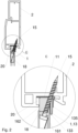
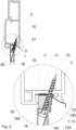
Fig. 3 cross section of jamb stile with connector and vapour-tight membrane as well as sealing and bonding agent and lining plate and enlarged-view D of lining plate assembly location by the jamb. -
Fig. 4 cross section of jamb stile with connector and lining plate and enlarged-view F of lining plate assembly location by the jamb without screws. -
Fig. 5 cross section of jamb stile with connector and vapour-tight membrane as well as sealing and bonding agent and lining plate and enlarged-view E of lining plate assembly location by the jamb without screws and with coupling element. -
Fig. 6 cross section and perspective views of connector without spacer plates. -
Fig. 7 cross section and perspective views of connector with spacer plates. -
Fig. 8 cross section and perspective views of connector without spacer plates and with coupling element. -
Fig. 9 cross section and perspective views of connector with spacer plates and with coupling element. - The assembly connector is a metal element, with the help of which the roof window lining is assembled around
jamb 2.Assembly connector 1 is constructed out ofbase 11, with at least oneridge 12 and stopface 13. The stop face features elastic properties and is constructed out offirst arm 131 andsecond arm 132. Rotation axis O' runs alongtop edge 133 which connects the said arms, and both the arms tilt slightly from their initial position i.e. prior to the assembly connector being seated in the jamb groove, so that distance di between these arms in their assembled position is smaller than in their initial position, before assembly, when it is in a relaxed position. The assembly connector also featuresbottom edge 134 which connects stopface 13second arm 132 with itsthird arm 135, and the distance betweensecond arm 131 andthird arm 135 is d2, and d2≥0. Distance d2 decreases or remains the same once the assembly connector has been seated on the lining assembly groove. - In the second embodiment, the assembly connector according to the first embodiment, in order to limit the maximum reduction of distance di between
first arm 131 andsecond arm 132, also featuresspacer plate 14, which preferably is an extension ofassembly connector base 11. - In the third embodiment, the assembly connector according to the first or second embodiments features a coupling element to initially support lining
plates lip 136 protruding from stop face 13first arm 131, and its crest is oriented towards assembly connector base (11). In the initial lining plate support position,lip 136 is in a catch type connection withplate lip 136. - The roof window lining assembly unit comprises an assembly connector according to any one of the embodiments 1-3, attachment measures, in
particular screws 15 and a lining. The lining is constructed out of four plates:top plate 16,bottom plate 17 and twoside plates 18, so that the length of one edge of each plate, referred to as the adjacent edge, is appropriate for the length of a corresponding roof window jamb stile which it is adjacent to in its assembled state. A top strip, bottom strip and two side strips are attached to each correspondingprotective frame plate - Method for assembling the lining around a roof window entails preparing an assembly unit and then the following:
- application of a layer of sealing and
bonding agent 19 injamb groove 20, - positioning ends of vapour-
tight membrane 21 in eachjamb groove 20, on sealing andbonding agent 19, so that vapour-tight membrane 21 in its assembled state shields the inside of the room around the window under the lining, - insertion of at least one assembly connector according to any one of the embodiments 1-3 into each
jamb groove 20 onto vapour-tight membrane 21, - push-in method insertion of the top 16, bottom 17 and two
side lining plates 18 intocorresponding jamb grooves 20 so that the edge of each lining plate abuts againstassembly connector base 11, and each plate is initially supported in a jamb groove. Initial support in the proposed embodiment is performed using an assembly connector coupling element in the form oflip 136 protruding from stop face 13first arm 131.Lip 136 establishes a catch type connection with a lining plate. - In another embodiment, where the assembly connector does not feature a coupling element, lining
plate inner wall 162 side, so that attachment measures 15 pass throughappropriate lining plate assembly connector base 11 all the way to the jamb. Then liningplates
Claims (20)
- Roof window lining assembly connector (1), designed to be seated in a jamb groove (20), characterized in that it is an elastic element, which once seated in jamb groove (20) exerts constant pressure on its opposite walls.
- Assembly connector according to claim 1 characterized in that it comprises a base (11), with at least one ridge (12) and a stop face (13), which is at an angle relative to the base (11), so that the stop face (13) comprises a top edge (133), with the axis of rotation (O') of a stop face first arm (131) and a second arm (132) passing through it, and the distance between the two stop face arms is di wherein di>0.
- The assembly connector according to claim 1 or 2 characterized in that the stop face (13) comprises a bottom edge (134) which connects the stop face (13) second arm (132) with its third arm (135), and the distance between the second arm (132) and the third arm (135) is d2, and d2≥0.
- The assembly connector according to claim 1 or 2, or 3 characterized in that there is a spacer plate (14) between the stop face (13) first arm (131) and the second arm (132), which defines the minimum distance di between the arms.
- The assembly connector according to claim 4 characterized in that the spacer plate (14) is an extension of assembly connector base (11).
- The assembly connector according to claim 1 or 2, or 3, or 4, or 5 is characterized in that it features a coupling element to initially support lining plates (16, 17, 18) in jamb groove (20).
- The assembly connector according to claim 6 characterized in that the coupling element constitutes a lip (136) on the stop face (13) first arm (131), and its crest is oriented towards assembly connector base (11).
- The roof window lining assembly unit characterized in that it comprises the assembly connector (1) according to claims 1-7, and a lining.
- The assembly unit according to claim 8 characterized in that it comprises an attachment measures, in particulae a screws.
- The assembly unit according to claim 6 or 7 characterized in that it comprises a vapour-tight membrane (21).
- The assembly unit according to claim 6 or 7, or 8 characterized in that it comprises a sealing and a bonding agent (19) to be placed between the connector (1) and a jamb groove (20) bottom.
- The assembly unit according to claim 6 or 7, or 8, or 9 characterized in that the lining comprises a four plates: a top plate (16), a bottom plate (17) and two side plates (18), so that the length of one edge of each plate, referred to as the adjacent edge, is appropriate for the length of a corresponding roof window jamb (2) stile which it is adjacent to in its assembled state and a top strip, a bottom strip and two side strips are attached to each corresponding protective frame plate, and each strip features an attachment arm, so that there is a recess between the attachment arm and the strip edge, wherein an edge of an appropriate protective frame plate is seated.
- Method for assembling the lining around a roof window using the assembly unit according to claims 8-12, wherein the roof window is constructed out of the jamb (2) and a sash with a glazing unit, and the jamb (2) is a frame constructed out of a stiles, so that each jamb (2) stile features jamb groove (20), characterized in that the method entails the following:- preparation of the assembly unit according to claims 8-12,- insertion of at least one assembly connector (1) according to claims 1-7 into each jamb groove (20),- push-in method insertion of the top (16), the bottom (17) and the two side lining plates (18) into corresponding jamb grooves (20) so that the edge of each lining plate abuts against assembly connector (1) base (11), and the lining plates (16, 17, 18) are initially supported in the jamb groove.
- The assembly method according to claim 13 is characterized in that during push-in method insertion of the lining plates (16, 17, 18) into jamb groove (20), assembly connector (1) coupling element initially supports the lining plates (16, 17, 18) in the jamb groove (20) .
- The assembly method according to claim 14 characterized in that the connector (1) lip (136) is the coupling element and it establishes a catch-type connection with lining plate (16, 17, 18).
- The assembly method according to claim 13 or 14, or 15 characterized in that the next stage entails inserting attachment measures (15) into each lining plate from the plate lining outer wall side, so that the attachment measures (15) pass through the appropriate lining plate, assembly connector (1) stop face (13) at an angle relative to assembly connector base (11) all the way to the jamb.
- The assembly method according to claim 13 or 14 or 15, or 16 characterized in that following preparation of an assembly unit, a layer of sealing and a bonding agent (19) is applied in the jamb groove (20).
- The assembly method according to claim 13 or 14, or 15, or 16 characterized in that the sealing and bonding agent (19) is located on the lining plate edges (16, 17, 18) .
- The assembly method according to claim 13 or 14, or 15, or 16, or 17, or 18 characterized in that before placing the connector (1) in the jamb groove (20), ends of vapour-tight membrane (21) are positioned in the jamb groove (20), preferably on the sealing and bonding agent (19), and the vapour-tight membrane (21) in its assembled state shields the inside of the room around the window under the lining.
- The assembly method according to claim 13 or 14, or 15, or 16, or 17, or 18, or 19 characterized in that the lining plates (16, 17, 18) are attached to walls around the jamb using the attachment measures.
Applications Claiming Priority (1)
| Application Number | Priority Date | Filing Date | Title |
|---|---|---|---|
| PL445470A PL445470A1 (en) | 2023-07-05 | 2023-07-05 | Roof window lining assembly connector, lining assembly kit and method of assembling the lining around the roof window using the assembly kit |
Publications (1)
| Publication Number | Publication Date |
|---|---|
| EP4488468A1 true EP4488468A1 (en) | 2025-01-08 |
Family
ID=91954076
Family Applications (1)
| Application Number | Title | Priority Date | Filing Date |
|---|---|---|---|
| EP24186857.9A Pending EP4488468A1 (en) | 2023-07-05 | 2024-07-05 | Roof window lining assembly connector, lining assembly unit and method for assembling lining around a roof window using the assembly unit |
Country Status (2)
| Country | Link |
|---|---|
| EP (1) | EP4488468A1 (en) |
| PL (1) | PL445470A1 (en) |
Citations (4)
| Publication number | Priority date | Publication date | Assignee | Title |
|---|---|---|---|---|
| DE2856401A1 (en) * | 1978-12-28 | 1980-07-03 | Hermann Gruber | Wall window type opening covering cladding - has profiled soffit frame and jamb frame sections plugged together |
| WO2008138334A1 (en) * | 2007-05-11 | 2008-11-20 | Vkr Holding A/S | An internal panel for a window structure, the window structure itself and a method of installing the panel |
| FR3063099A1 (en) * | 2017-02-17 | 2018-08-24 | Mc France | JOINERY FOR AN OPENING UNDERTAKEN IN A BUILDING WALL |
| EP3792438B1 (en) | 2019-09-13 | 2025-11-26 | VKR Holding A/S | Window lining assembly with improved fittings and method for installing such a lining assembly on a window |
Family Cites Families (3)
| Publication number | Priority date | Publication date | Assignee | Title |
|---|---|---|---|---|
| DK173990B1 (en) * | 1997-07-09 | 2002-03-25 | Vkr Holding As | Skylight window with connection collar for a vapor barrier membrane |
| PL200789B1 (en) * | 2001-03-01 | 2009-02-27 | Florek Krystyna | Skylight window frame and method of mounting the skylight window frame in a roof |
| PL2615219T3 (en) * | 2012-01-13 | 2015-08-31 | Vkr Holding As | A kit of parts for mounting a window lining and method of providing a window lining using said kit of parts |
-
2023
- 2023-07-05 PL PL445470A patent/PL445470A1/en unknown
-
2024
- 2024-07-05 EP EP24186857.9A patent/EP4488468A1/en active Pending
Patent Citations (4)
| Publication number | Priority date | Publication date | Assignee | Title |
|---|---|---|---|---|
| DE2856401A1 (en) * | 1978-12-28 | 1980-07-03 | Hermann Gruber | Wall window type opening covering cladding - has profiled soffit frame and jamb frame sections plugged together |
| WO2008138334A1 (en) * | 2007-05-11 | 2008-11-20 | Vkr Holding A/S | An internal panel for a window structure, the window structure itself and a method of installing the panel |
| FR3063099A1 (en) * | 2017-02-17 | 2018-08-24 | Mc France | JOINERY FOR AN OPENING UNDERTAKEN IN A BUILDING WALL |
| EP3792438B1 (en) | 2019-09-13 | 2025-11-26 | VKR Holding A/S | Window lining assembly with improved fittings and method for installing such a lining assembly on a window |
Also Published As
| Publication number | Publication date |
|---|---|
| PL445470A1 (en) | 2025-01-07 |
Similar Documents
| Publication | Publication Date | Title |
|---|---|---|
| US4691489A (en) | Joint seal assembly | |
| US8567142B2 (en) | Mounting fixture for fire-rated structurally glazed glass | |
| US4008552A (en) | Wall structure and elements therefor | |
| US10156089B2 (en) | Fenestration supplement systems and methods of use | |
| US20250283370A1 (en) | Window assembly for mitigating fluid ingress | |
| US12320182B2 (en) | Fenestration unit with two-part frame | |
| US20250341126A1 (en) | Apparatus and method for installing a closure in a building | |
| CN108316810B (en) | Door and window system | |
| EP4488468A1 (en) | Roof window lining assembly connector, lining assembly unit and method for assembling lining around a roof window using the assembly unit | |
| EP3854980A1 (en) | A glazing bead | |
| CN111963021B (en) | Splicing method of aluminum alloy door and window frames | |
| GB2525183A (en) | Fenestration products | |
| US8028479B2 (en) | Interlocking structural glazing panels | |
| RU76058U1 (en) | INTEGRATED WINDOW | |
| EP2933419B1 (en) | Fenestration products | |
| CN216841179U (en) | Mullion connecting piece device for doors and windows | |
| JPH0425455Y2 (en) | ||
| JP2001262792A (en) | Panel mounting structure of building | |
| GB2408768A (en) | Releasable double frame | |
| AU2024205717A1 (en) | Improved window stay and assembly | |
| CN118257479A (en) | Split type narrow frame curtain window | |
| RU132821U1 (en) | MANSARD WINDOW | |
| JP2025131019A (en) | Sash manufacturing method | |
| NO20230248A1 (en) | Glazing bead | |
| GB2600978A (en) | A mounting assembly |
Legal Events
| Date | Code | Title | Description |
|---|---|---|---|
| PUAI | Public reference made under article 153(3) epc to a published international application that has entered the european phase |
Free format text: ORIGINAL CODE: 0009012 |
|
| STAA | Information on the status of an ep patent application or granted ep patent |
Free format text: STATUS: THE APPLICATION HAS BEEN PUBLISHED |
|
| AK | Designated contracting states |
Kind code of ref document: A1 Designated state(s): AL AT BE BG CH CY CZ DE DK EE ES FI FR GB GR HR HU IE IS IT LI LT LU LV MC ME MK MT NL NO PL PT RO RS SE SI SK SM TR |
|
| STAA | Information on the status of an ep patent application or granted ep patent |
Free format text: STATUS: REQUEST FOR EXAMINATION WAS MADE |
|
| 17P | Request for examination filed |
Effective date: 20250610 |