EP4488451A1 - Work vehicle with telescopic arm, in particular a telehandler - Google Patents
Work vehicle with telescopic arm, in particular a telehandler Download PDFInfo
- Publication number
- EP4488451A1 EP4488451A1 EP24184173.3A EP24184173A EP4488451A1 EP 4488451 A1 EP4488451 A1 EP 4488451A1 EP 24184173 A EP24184173 A EP 24184173A EP 4488451 A1 EP4488451 A1 EP 4488451A1
- Authority
- EP
- European Patent Office
- Prior art keywords
- segment
- vehicle according
- roller train
- rollers
- vehicle
- Prior art date
- Legal status (The legal status is an assumption and is not a legal conclusion. Google has not performed a legal analysis and makes no representation as to the accuracy of the status listed.)
- Pending
Links
Images





Classifications
-
- E—FIXED CONSTRUCTIONS
- E02—HYDRAULIC ENGINEERING; FOUNDATIONS; SOIL SHIFTING
- E02F—DREDGING; SOIL-SHIFTING
- E02F3/00—Dredgers; Soil-shifting machines
- E02F3/04—Dredgers; Soil-shifting machines mechanically-driven
- E02F3/28—Dredgers; Soil-shifting machines mechanically-driven with digging tools mounted on a dipper- or bucket-arm, i.e. there is either one arm or a pair of arms, e.g. dippers, buckets
- E02F3/30—Dredgers; Soil-shifting machines mechanically-driven with digging tools mounted on a dipper- or bucket-arm, i.e. there is either one arm or a pair of arms, e.g. dippers, buckets with a dipper-arm pivoted on a cantilever beam, i.e. boom
- E02F3/306—Dredgers; Soil-shifting machines mechanically-driven with digging tools mounted on a dipper- or bucket-arm, i.e. there is either one arm or a pair of arms, e.g. dippers, buckets with a dipper-arm pivoted on a cantilever beam, i.e. boom with telescopic dipper-arm or boom
-
- B—PERFORMING OPERATIONS; TRANSPORTING
- B66—HOISTING; LIFTING; HAULING
- B66C—CRANES; LOAD-ENGAGING ELEMENTS OR DEVICES FOR CRANES, CAPSTANS, WINCHES, OR TACKLES
- B66C23/00—Cranes comprising essentially a beam, boom, or triangular structure acting as a cantilever and mounted for translatory of swinging movements in vertical or horizontal planes or a combination of such movements, e.g. jib-cranes, derricks, tower cranes
- B66C23/62—Constructional features or details
- B66C23/64—Jibs
- B66C23/70—Jibs constructed of sections adapted to be assembled to form jibs or various lengths
- B66C23/701—Jibs constructed of sections adapted to be assembled to form jibs or various lengths telescopic
- B66C23/707—Jibs constructed of sections adapted to be assembled to form jibs or various lengths telescopic guiding devices for telescopic jibs
-
- B—PERFORMING OPERATIONS; TRANSPORTING
- B66—HOISTING; LIFTING; HAULING
- B66F—HOISTING, LIFTING, HAULING OR PUSHING, NOT OTHERWISE PROVIDED FOR, e.g. DEVICES WHICH APPLY A LIFTING OR PUSHING FORCE DIRECTLY TO THE SURFACE OF A LOAD
- B66F9/00—Devices for lifting or lowering bulky or heavy goods for loading or unloading purposes
- B66F9/06—Devices for lifting or lowering bulky or heavy goods for loading or unloading purposes movable, with their loads, on wheels or the like, e.g. fork-lift trucks
- B66F9/065—Devices for lifting or lowering bulky or heavy goods for loading or unloading purposes movable, with their loads, on wheels or the like, e.g. fork-lift trucks non-masted
- B66F9/0655—Devices for lifting or lowering bulky or heavy goods for loading or unloading purposes movable, with their loads, on wheels or the like, e.g. fork-lift trucks non-masted with a telescopic boom
-
- F—MECHANICAL ENGINEERING; LIGHTING; HEATING; WEAPONS; BLASTING
- F16—ENGINEERING ELEMENTS AND UNITS; GENERAL MEASURES FOR PRODUCING AND MAINTAINING EFFECTIVE FUNCTIONING OF MACHINES OR INSTALLATIONS; THERMAL INSULATION IN GENERAL
- F16C—SHAFTS; FLEXIBLE SHAFTS; ELEMENTS OR CRANKSHAFT MECHANISMS; ROTARY BODIES OTHER THAN GEARING ELEMENTS; BEARINGS
- F16C29/00—Bearings for parts moving only linearly
- F16C29/04—Ball or roller bearings
- F16C29/045—Ball or roller bearings having rolling elements journaled in one of the moving parts
- F16C29/046—Ball or roller bearings having rolling elements journaled in one of the moving parts with balls journaled in pockets
-
- F—MECHANICAL ENGINEERING; LIGHTING; HEATING; WEAPONS; BLASTING
- F16—ENGINEERING ELEMENTS AND UNITS; GENERAL MEASURES FOR PRODUCING AND MAINTAINING EFFECTIVE FUNCTIONING OF MACHINES OR INSTALLATIONS; THERMAL INSULATION IN GENERAL
- F16C—SHAFTS; FLEXIBLE SHAFTS; ELEMENTS OR CRANKSHAFT MECHANISMS; ROTARY BODIES OTHER THAN GEARING ELEMENTS; BEARINGS
- F16C29/00—Bearings for parts moving only linearly
- F16C29/12—Arrangements for adjusting play
-
- F—MECHANICAL ENGINEERING; LIGHTING; HEATING; WEAPONS; BLASTING
- F16—ENGINEERING ELEMENTS AND UNITS; GENERAL MEASURES FOR PRODUCING AND MAINTAINING EFFECTIVE FUNCTIONING OF MACHINES OR INSTALLATIONS; THERMAL INSULATION IN GENERAL
- F16C—SHAFTS; FLEXIBLE SHAFTS; ELEMENTS OR CRANKSHAFT MECHANISMS; ROTARY BODIES OTHER THAN GEARING ELEMENTS; BEARINGS
- F16C2326/00—Articles relating to transporting
Definitions
- the present invention relates to the field of work vehicles with telescopic arm such as telehandler.
- Telescopic arms are widely used in the field of work machines, especially in mining companies, where the telescopic work arm plays an important role in the field of material loading operations.
- Telescopic arms are also used in firefighting vehicles for rescuing people.
- the arm comprises a plurality of interconnected segments, in which the first segment ES1 is hinged to the chassis of the work vehicle by means of a "constrained" end.
- Vehicles are known in which the extendable arm comprises more than two segments, such as for example the so-called “telehandler” or “telescopic handler”.
- the ability to extend the arm is an essential aspect, therefore, they can also include four or more segments, each of which is equipped with a hydraulic actuator that allows it to extend or retract with respect to the segment that precedes it.
- a segment is fitted into another segment and sliding is facilitated by pads made of a very resistant material which guarantees excellent sliding to sliding parts such as Teflon TM .
- the arms of telehandler vehicles are made with box-shaped elements with a rectangular section, so as to avoid any axial rotation between one segment and another and to satisfy particularly demanding tasks.
- At least two of pads are arranged on the inner faces of the "free" end of the outer segment, at least further two pairs of pads are associated with the outer faces of the inner end of the inner segment.
- the pads arranged on operationally vertical walls are used to support lateral swinging of the arm, for example, when the vehicle does not work on level ground, or when the load supported by the arm produces a twisting moment.
- the pads arranged on the operatively horizontal walls are particularly stressed when the arm extends or retracts while supporting a load, in any operating condition.
- the object of the present invention is to propose a more telescopic arm in which the aforementioned problems are reduced.
- an aim is to eliminate the pollution due to the falling on the ground of the material abraded from the pads, to decrease the effort required to extend and retract the arm and to reduce the stop time of the machine and the relative costs.
- the rollers are not associated directly with the relative segment, but by means of a frame arranged to be fixed to a segment by means of a clearance adjustment system.
- the frame with the relative rollers is internally associated in the cavity of a segment which supports a further internal segment.
- the frame with the relative rollers is internally associated with the cavity of a segment supported by a further external segment and the rollers project externally from the wall of the relative segment through suitable openings.
- Fig. 1 shows a vehicle VEH equipped with a telescopic arm A, hinged to the vehicle chassis, so that the arm can be raised and lowered.
- the vehicle is equipped with wheels W, but may be equipped with tracks.
- the vehicle is a so-called telehandler, equipped with an extendable arm A with a tubular and rectangular cross-section, intended for lifting loads.
- the arm may consist of two or more segments, one inside the other, which extend according to a predetermined pattern of extension.
- Fig. 2 shows a longitudinal section of the telescopic arm of the present invention.
- the arm comprises an external segment ES and an internal segment IS, in particular, in Fig. 2 , the internal segment IS is completely inserted in the external segment ES.
- Fig. 3 shows a longitudinal section of the telescopic arm in which the internal segment IS is partially extracted from the external segment ES defining a partially extended condition.
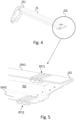
- Fig. 4 shows a perspective view of the outer end IS1 and the inner end IS2 of the inner segment.
- the internal end IS2 is referred to as "internal end”, as it is intended, under operating conditions, to always be within the external segment. It is accessible and visible only when the arm is disassembled.
- the external end IS1 is referred to as “external end”, as it always remains visible and accessible, regardless of the relative operating condition.
- Fig. 5 shows a perspective view of the same internal end IS2 with the side facing the observer in transparency.
- the arm is hinged to the vehicle frame so that it can rotate around a horizontal axis X, i.e. parallel to the vehicle's support ground and the horizontal walls are parallel to the hinge axis. Therefore, it is immediate to identify the horizontal walls of each segment, since all segments have a rectangular tubular section.
- the upper roller set RTI1 is associated with the upper horizontal wall ISH1 on the upper horizontal face of the internal cavity ISC of the internal segment. Suitable rectangular openings allow the rollers to face externally.
- the lower roller set RTI2 is associated with the lower horizontal wall ISH2 on the outer face.
- the lower horizontal wall ISH2 can also be equipped with rectangular openings in order to partially embed the rollers of the lower train in the relative segment.
- the internal end IS2 of the internal segment is equipped with at least one pair of lateral pads ISP, i.e. associated externally to the vertical walls, so as to allow the reciprocal movement of the internal segment with respect to the relative external segment even in heeling conditions.
- pads can be better seen in Fig. 9 .
- the collar supports an upper roller set RTE1 and a lower roller set RTE2. Both upper and lower trains are supported in the inner faces of the collar ESC. Therefore, with the roller trains associated with the internal segment and the roller trains associated with the external segment it is possible to allow the reciprocal sliding of the two segments between the extended condition and the retracted condition and vice versa. Naturally, also in this case the collar supports at least one pair of pads ESP associated internally with the vertical walls of the collar.
- the roller trains comprise at least one pair of rollers R maintained parallel to each other by a pair of perforated plates F parallel to each other, perforated so as to support the axes of the rollers.
- one roller train is fixed externally and one internally with respect to the cavity ISC of the tubular section defined by the segment.
- both trains may be fixed externally or internally in relation to the dimensions of the cavity of the external segment with respect to the dimensions of the internal segment.
- the roller train of the inner end IS2 of the inner segment IS is associated with a relative segment by means of a hinge (HI) arranged so as to allow the roller train to tilt along an axis (Y) parallel to the hinge axis (X) of the telescopic arm.
- a hinge HI
- this solution makes it possible to maintain the distribution of forces on all the rollers of the train even when the internal segment is completely extracted from the external segment.
- roller set is associated in the segment cavity is not essential, as the same principle can be applied to the lower roller set RTI2.
- the ESP and ISP pads are made with a biocompatible material such as bioplastic, ensuring acceptable performance for pads associated with the vertical walls of the segments.
- Another advantage of the present invention is that of eliminating the dispersion of microplastics with the use of pads in biocompatible materials on vertical walls and roller trains on horizontal walls.
- the pads subject to greater wear are those associated with the horizontal walls, which in the present invention are replaced by roller trains.
Landscapes
- Engineering & Computer Science (AREA)
- General Engineering & Computer Science (AREA)
- Mechanical Engineering (AREA)
- Structural Engineering (AREA)
- Transportation (AREA)
- Civil Engineering (AREA)
- Life Sciences & Earth Sciences (AREA)
- Geology (AREA)
- Mining & Mineral Resources (AREA)
- Bearings For Parts Moving Linearly (AREA)
Abstract
Description
- The present invention relates to the field of work vehicles with telescopic arm such as telehandler.
- Telescopic arms are widely used in the field of work machines, especially in mining companies, where the telescopic work arm plays an important role in the field of material loading operations.
- Telescopic arms are also used in firefighting vehicles for rescuing people.
- The arm comprises a plurality of interconnected segments, in which the first segment ES1 is hinged to the chassis of the work vehicle by means of a "constrained" end.
- Vehicles are known in which the extendable arm comprises more than two segments, such as for example the so-called "telehandler" or "telescopic handler".
- In these work vehicles, the ability to extend the arm is an essential aspect, therefore, they can also include four or more segments, each of which is equipped with a hydraulic actuator that allows it to extend or retract with respect to the segment that precedes it.
- A segment is fitted into another segment and sliding is facilitated by pads made of a very resistant material which guarantees excellent sliding to sliding parts such as Teflon™.
- The arms of telehandler vehicles are made with box-shaped elements with a rectangular section, so as to avoid any axial rotation between one segment and another and to satisfy particularly demanding tasks.
- At least two of pads are arranged on the inner faces of the "free" end of the outer segment, at least further two pairs of pads are associated with the outer faces of the inner end of the inner segment.
- The pads arranged on operationally vertical walls are used to support lateral swinging of the arm, for example, when the vehicle does not work on level ground, or when the load supported by the arm produces a twisting moment.
- The pads arranged on the operatively horizontal walls are particularly stressed when the arm extends or retracts while supporting a load, in any operating condition.
- This means that when one segment slides:
- the material of the horizontal pads is abraded and falls on the ground polluting it,
- the friction between the pads and the segment increases the effort required to extend and retract the segment, which results in an increase in the pressure of the hydraulic actuator which allows it to extend or retract.
- Furthermore, the pads, due to abrasion, must be replaced after a certain number of working hours, resulting in machine downtime and costs.
- Unless specifically excluded in the detailed description that follows, what is described in this chapter is to be considered as an integral part of the detailed description.
- The object of the present invention is to propose a more telescopic arm in which the aforementioned problems are reduced.
- In particular, an aim is to eliminate the pollution due to the falling on the ground of the material abraded from the pads, to decrease the effort required to extend and retract the arm and to reduce the stop time of the machine and the relative costs.
- Preferably, the rollers are not associated directly with the relative segment, but by means of a frame arranged to be fixed to a segment by means of a clearance adjustment system.
- According to a preferred variant of the invention, the frame with the relative rollers is internally associated in the cavity of a segment which supports a further internal segment.
- According to another preferred variant of the invention, the frame with the relative rollers is internally associated with the cavity of a segment supported by a further external segment and the rollers project externally from the wall of the relative segment through suitable openings.
- The dependent claims describe preferred variants of the invention, forming an integral part of the present description.
- Further objects and advantages of the present invention will become clear from the detailed description that follows of an embodiment of the same (and of its variants) and from the annexed drawings given for purely explanatory and non-limiting purposes, in which:
-
Fig. 1 shows an example of a work vehicle equipped with a telescopic arm with a rectangular section; -
Figs. 2 and 3 show a longitudinal section according to a side view of the telescopic arm ofFig. 1 , modified according to the present invention, respectively in a retracted configuration and in a partially extended configuration; -
Fig. 4 shows a perspective view of a portion of the arm ofFigs. 2 and 3 ; -
Fig. 5 shows another perspective view of a detail of the arm portion ofFig. 4 ; -
Figs. 6 and 7 show a detail of another portion of the arm ofFigs. 2 and 3 according to two perspective and axial views, respectively; -
Fig. 8 shows a component present both in the portion of the arm ofFig. 4 and in the portion of the arm ofFigs. 6 and 7 ; -
Fig. 9 shows an axial view of the portion of the arm ofFigs. 4 and 5 ; -
Figs. 10 - 12 show a preferred variant of the invention which provides for the connection of the component ofFig. 8 according to a floating configuration. - The same reference numbers and letters in the figures identify the same elements or components or functions.
- It should also be noted that the terms "first", "second", "third", "superior", "inferior" and the like may be used herein to distinguish various items. These terms do not imply a spatial, sequential, or hierarchical order for the modified items unless specifically indicated or inferred from the text.
- The elements and characteristics illustrated in the various preferred embodiments, including the drawings, can be combined with each other without however departing from the scope of protection of the present application as described below.
-
Fig. 1 shows a vehicle VEH equipped with a telescopic arm A, hinged to the vehicle chassis, so that the arm can be raised and lowered. - The vehicle is equipped with wheels W, but may be equipped with tracks.
- The vehicle is a so-called telehandler, equipped with an extendable arm A with a tubular and rectangular cross-section, intended for lifting loads.
- The arm may consist of two or more segments, one inside the other, which extend according to a predetermined pattern of extension.
-
Fig. 2 shows a longitudinal section of the telescopic arm of the present invention. - The arm comprises an external segment ES and an internal segment IS, in particular, in
Fig. 2 , the internal segment IS is completely inserted in the external segment ES. -
Fig. 3 , on the other hand, shows a longitudinal section of the telescopic arm in which the internal segment IS is partially extracted from the external segment ES defining a partially extended condition. -
Fig. 4 shows a perspective view of the outer end IS1 and the inner end IS2 of the inner segment. - The internal end IS2 is referred to as "internal end", as it is intended, under operating conditions, to always be within the external segment. It is accessible and visible only when the arm is disassembled.
- On the contrary, the external end IS1 is referred to as "external end", as it always remains visible and accessible, regardless of the relative operating condition.
-
Fig. 5 shows a perspective view of the same internal end IS2 with the side facing the observer in transparency. - An upper roller train RTI1 and a lower roller train RTI2 are therefore clearly visible.
- They are called upper and lower in relation to the fact that they are associated with the operatively horizontal upper ISH1 and lower walls ISH2 of the inner segment.
- It is worth highlighting that the arm is hinged to the vehicle frame so that it can rotate around a horizontal axis X, i.e. parallel to the vehicle's support ground and the horizontal walls are parallel to the hinge axis. Therefore, it is immediate to identify the horizontal walls of each segment, since all segments have a rectangular tubular section.
- According to the present invention, the upper roller set RTI1 is associated with the upper horizontal wall ISH1 on the upper horizontal face of the internal cavity ISC of the internal segment. Suitable rectangular openings allow the rollers to face externally.
- Conversely, the lower roller set RTI2 is associated with the lower horizontal wall ISH2 on the outer face. However, to limit the protrusion of the rollers, the lower horizontal wall ISH2 can also be equipped with rectangular openings in order to partially embed the rollers of the lower train in the relative segment.
- The internal end IS2 of the internal segment is equipped with at least one pair of lateral pads ISP, i.e. associated externally to the vertical walls, so as to allow the reciprocal movement of the internal segment with respect to the relative external segment even in heeling conditions. Such pads can be better seen in
Fig. 9 . - With reference to
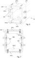
Figs. 6 and 7 , the free end ES1 of the outer segment ES is shown. This end is referred to as "free", in contrast with the relative opposite end ES2 "constrained", as it is hinged to the vehicle chassis. - The free end ES1 includes a sort of collar ESC which has the purpose of structurally reinforcing the portion of the segment most stressed by the internal segment.
- The collar ESC comprises two portions, left and right, permanently fixed to the free end of the segment.
- The collar supports an upper roller set RTE1 and a lower roller set RTE2. Both upper and lower trains are supported in the inner faces of the collar ESC. Therefore, with the roller trains associated with the internal segment and the roller trains associated with the external segment it is possible to allow the reciprocal sliding of the two segments between the extended condition and the retracted condition and vice versa. Naturally, also in this case the collar supports at least one pair of pads ESP associated internally with the vertical walls of the collar.
- According to a preferred aspect of the present invention, the roller trains comprise at least one pair of rollers R maintained parallel to each other by a pair of perforated plates F parallel to each other, perforated so as to support the axes of the rollers.
- Preferably, the fastening of the roller trains is achieved through the perforated plates F, by means of through holes transverse to the support holes of the rollers.
- More preferably, spacers SP are interposed between the perforated plates F and the segment or collar with which they are intended to be associated, which allow for the clearance to be recovered.
- Advantageously:
- the wear of the rollers is much lower than that of the pads, their useful life is greater than that of the machine and therefore they do not need to be replaced, thus reducing maintenance times and therefore machine downtime,
- the rollers do not pollute because they are not abraded during their use,
- they decrease the effort required to extend and retract the arm, as the rolling friction between the rollers and the segment is less than the sliding friction between the pads and the segment.
- It should be noted that with regard to the internal segment, preferably one roller train is fixed externally and one internally with respect to the cavity ISC of the tubular section defined by the segment.
- However, it is possible to envisage that both trains may be fixed externally or internally in relation to the dimensions of the cavity of the external segment with respect to the dimensions of the internal segment.
- According to the preferred variant of
Figs. 10-12 , the roller train of the inner end IS2 of the inner segment IS is associated with a relative segment by means of a hinge (HI) arranged so as to allow the roller train to tilt along an axis (Y) parallel to the hinge axis (X) of the telescopic arm. - Advantageously, this solution makes it possible to maintain the distribution of forces on all the rollers of the train even when the internal segment is completely extracted from the external segment.
- The fact that the roller set is associated in the segment cavity is not essential, as the same principle can be applied to the lower roller set RTI2.
- According to a preferred aspect of the invention, the ESP and ISP pads are made with a biocompatible material such as bioplastic, ensuring acceptable performance for pads associated with the vertical walls of the segments.
- Another advantage of the present invention, in this case, is that of eliminating the dispersion of microplastics with the use of pads in biocompatible materials on vertical walls and roller trains on horizontal walls.
- In fact, the pads subject to greater wear are those associated with the horizontal walls, which in the present invention are replaced by roller trains.
- Variants of the non-limiting example described are possible, without however departing from the scope of protection of the present invention, including all equivalent embodiments for a person skilled in the art, to the contents of the claims.
- From the description given above, the person skilled in the art is capable of realizing the object of the invention without introducing further constructive details.
Claims (12)
- Work vehicle (VEH) comprising a telescopic arm (A) equipped with at least one external segment (ES) and an internal segment (IS) suitable for inserting axially in the external segment, wherein both segments have a tubular shape with a rectangular cross-section, and wherein the external segment has a first end (ES2) hinged to the vehicle to raise and lower according to a hinge axis (X) and wherein said rectangular cross-section defines horizontal walls, parallel to said hinge axis, and wherein to said horizontal walls roller trains are associated to reduce frictions during a procedure of extension or retraction of the telescopic arm.
- Vehicle according to claim 1, wherein said internal segment (IS) comprises an internal end (IS2) with respect to said external segment, and wherein a first roller train (RTI1) is associated with a first horizontal wall and a second roller train (RTI2) is associated with a second horizontal wall, opposite to the first one.
- Vehicle according to claim 2, wherein said first set of rollers is associated with an inner face of said first horizontal wall and wherein said first horizontal wall includes rectangular openings through which said rollers (R) of the first roller train project.
- Vehicle according to claim 2 or 3, wherein said second roller train (RTI2) is associated with an outer face of said second horizontal wall and wherein said second horizontal wall comprises rectangular openings for partially embedding the rollers (R) of the second roller train.
- Vehicle according to any one of the preceding claims 1 - 4, wherein said external segment (ES) comprises a free end (ES1) comprising a first (RTE1) and a second roller train (RTE2) associated on the internal faces of a relative first and second horizontal walls.
- The vehicle of claim 5 wherein said free end comprises a reinforcing collar (ESC) adapted to support said first and second sets of rollers.
- Vehicle according to any one of the preceding claims, wherein each roller train (RTE1, RTE2, RTI1, RTI2) comprises a pair of perforated plates (F) parallel to each other, perforated so as to support axes of the rollers.
- Vehicle according to any one of the preceding claims, wherein at least one roller train is associated with a relative segment, by means of a spacer (SP) able to adjust plays.
- Vehicle according to any one of the preceding claims, wherein at least one roller train is associated with a relative segment by means of a hinge (HI) arranged so as to allow the roller train to tilt according to an axis (Y) parallel to the hinge axis (X) of the telescopic arm.
- Vehicle according to any one of the preceding claims, wherein said roller trains are associated with horizontal walls of the inner and outer segment and in which pads (ESP, ISP) are associated with corresponding vertical walls of the inner and outer segment.
- Vehicle according to claim 10, wherein said pads are associated with said vertical walls in transverse sections passing through at least one respective roller train.
- Vehicle according to any one of the preceding claims, comprising at least one hydraulic actuator for controlling a reciprocal position between at least two segments defining the arm (A).
Applications Claiming Priority (1)
| Application Number | Priority Date | Filing Date | Title |
|---|---|---|---|
| IT102023000013413A IT202300013413A1 (en) | 2023-06-28 | 2023-06-28 | WORK VEHICLE WITH A TELESCOPIC ARM, ESPECIALLY A TELEHANDLER |
Publications (1)
| Publication Number | Publication Date |
|---|---|
| EP4488451A1 true EP4488451A1 (en) | 2025-01-08 |
Family
ID=87889819
Family Applications (1)
| Application Number | Title | Priority Date | Filing Date |
|---|---|---|---|
| EP24184173.3A Pending EP4488451A1 (en) | 2023-06-28 | 2024-06-25 | Work vehicle with telescopic arm, in particular a telehandler |
Country Status (2)
| Country | Link |
|---|---|
| EP (1) | EP4488451A1 (en) |
| IT (1) | IT202300013413A1 (en) |
Citations (7)
| Publication number | Priority date | Publication date | Assignee | Title |
|---|---|---|---|---|
| US3688930A (en) * | 1971-04-05 | 1972-09-05 | John F Shumaker | Extensible dipper stick for backhoe |
| GB1387563A (en) * | 1970-12-31 | 1975-03-19 | Harvey Plant Holdings Ltd | Telexcopic jib construction |
| US5267824A (en) * | 1989-04-26 | 1993-12-07 | Kabushiki Kaisha Japanic | Tool controlling mechanisms for excavator with telescopic arm |
| US5515654A (en) * | 1994-11-02 | 1996-05-14 | Anderson; Edward E. | Telescopic boom apparatus |
| US20070230947A1 (en) * | 2004-03-01 | 2007-10-04 | Chapman Leonard T | Telescoping camera crane |
| CN102659034A (en) * | 2012-04-12 | 2012-09-12 | 常州华通焊业股份有限公司 | Fast-telescoping energy-efficient lifting mechanism |
| US20130183028A1 (en) * | 2012-01-13 | 2013-07-18 | Leonard T. Chapman | Telescoping camera crane |
-
2023
- 2023-06-28 IT IT102023000013413A patent/IT202300013413A1/en unknown
-
2024
- 2024-06-25 EP EP24184173.3A patent/EP4488451A1/en active Pending
Patent Citations (7)
| Publication number | Priority date | Publication date | Assignee | Title |
|---|---|---|---|---|
| GB1387563A (en) * | 1970-12-31 | 1975-03-19 | Harvey Plant Holdings Ltd | Telexcopic jib construction |
| US3688930A (en) * | 1971-04-05 | 1972-09-05 | John F Shumaker | Extensible dipper stick for backhoe |
| US5267824A (en) * | 1989-04-26 | 1993-12-07 | Kabushiki Kaisha Japanic | Tool controlling mechanisms for excavator with telescopic arm |
| US5515654A (en) * | 1994-11-02 | 1996-05-14 | Anderson; Edward E. | Telescopic boom apparatus |
| US20070230947A1 (en) * | 2004-03-01 | 2007-10-04 | Chapman Leonard T | Telescoping camera crane |
| US20130183028A1 (en) * | 2012-01-13 | 2013-07-18 | Leonard T. Chapman | Telescoping camera crane |
| CN102659034A (en) * | 2012-04-12 | 2012-09-12 | 常州华通焊业股份有限公司 | Fast-telescoping energy-efficient lifting mechanism |
Also Published As
| Publication number | Publication date |
|---|---|
| IT202300013413A1 (en) | 2024-12-28 |
Similar Documents
| Publication | Publication Date | Title |
|---|---|---|
| EP2879983B1 (en) | Traveler roller | |
| DE19534291A1 (en) | Rail mounted shelving equipment for production line exchange | |
| DE10347571A1 (en) | printing unit | |
| ITTV20130093A1 (en) | MULTIFILE FRAME FOR CUTTING BLADES OF STONE MATERIAL IN PLATE | |
| ITMO990220A1 (en) | UNIVERSAL TRAVEL GROUP FOR CRANE LEGS OR SIMILAR | |
| CN113501449B (en) | Work machines and work machine outrigger components | |
| CN209724357U (en) | A new type of rapid unloading device for shield machine segments | |
| US4392554A (en) | Lift mast assembly | |
| DE2514304A1 (en) | BURDOOR FOR A RAIL VEHICLE | |
| DE10347573B4 (en) | Printing unit and a method for moving a frame part | |
| CN108275626A (en) | A kind of aerial lift device with insulated arm working bucket lifting structure | |
| DE102012208058B4 (en) | Cross force reducing support device | |
| CN211496612U (en) | A gantry crane bracket with lifting function | |
| RU163788U1 (en) | UNIVERSAL AUTONOMOUS LOADING HYDRAULIC ARROW | |
| CN220376157U (en) | Hoisting mechanism of gantry bridge crane | |
| CN102802838B (en) | The device of replacing fan-shaped section in the continuous casting billet guide mechanism for the continuous casting installation for casting of liquid metal of casting | |
| RU2407695C1 (en) | Load lifting table | |
| DE102014005469A1 (en) | Curb weight reduction for inloader vehicles | |
| EP2711211B1 (en) | Wheel suspension for a heavy duty transport vehicle and heavy duty transport vehicle using such a wheel suspension | |
| CN208980223U (en) | A kind of wear-resistant guiding device of automobile crane supporting leg | |
| CN110182498B (en) | Frame for vertical box body and transport vehicle | |
| CN118220740A (en) | Double-sided roller elevator chain | |
| DE102014010279B4 (en) | Device for spanning a revolving platform of a mobile work machine to increase the load-bearing capacity and durability | |
| IT202300021480A1 (en) | LOAD BALANCING SYSTEM ON THE PLATFORMS OF GENERAL TRANSPORT MEANS | |
| DE1067195B (en) |
Legal Events
| Date | Code | Title | Description |
|---|---|---|---|
| PUAI | Public reference made under article 153(3) epc to a published international application that has entered the european phase |
Free format text: ORIGINAL CODE: 0009012 |
|
| STAA | Information on the status of an ep patent application or granted ep patent |
Free format text: STATUS: THE APPLICATION HAS BEEN PUBLISHED |
|
| AK | Designated contracting states |
Kind code of ref document: A1 Designated state(s): AL AT BE BG CH CY CZ DE DK EE ES FI FR GB GR HR HU IE IS IT LI LT LU LV MC ME MK MT NL NO PL PT RO RS SE SI SK SM TR |
|
| STAA | Information on the status of an ep patent application or granted ep patent |
Free format text: STATUS: REQUEST FOR EXAMINATION WAS MADE |
|
| 17P | Request for examination filed |
Effective date: 20250708 |
|
| GRAP | Despatch of communication of intention to grant a patent |
Free format text: ORIGINAL CODE: EPIDOSNIGR1 |
|
| STAA | Information on the status of an ep patent application or granted ep patent |
Free format text: STATUS: GRANT OF PATENT IS INTENDED |
|
| RIC1 | Information provided on ipc code assigned before grant |
Ipc: E02F 3/30 20060101AFI20260325BHEP Ipc: B66C 23/70 20060101ALI20260325BHEP Ipc: F16C 29/02 20060101ALI20260325BHEP Ipc: F16C 29/04 20060101ALI20260325BHEP Ipc: F16C 29/12 20060101ALI20260325BHEP Ipc: F16C 33/20 20060101ALI20260325BHEP |
|
| INTG | Intention to grant announced |
Effective date: 20260408 |
|
| GRAS | Grant fee paid |
Free format text: ORIGINAL CODE: EPIDOSNIGR3 |
|
| GRAA | (expected) grant |
Free format text: ORIGINAL CODE: 0009210 |
|
| STAA | Information on the status of an ep patent application or granted ep patent |
Free format text: STATUS: THE PATENT HAS BEEN GRANTED |