EP4488129A1 - Pneumatisches ventilsystem - Google Patents
Pneumatisches ventilsystem Download PDFInfo
- Publication number
- EP4488129A1 EP4488129A1 EP24180358.4A EP24180358A EP4488129A1 EP 4488129 A1 EP4488129 A1 EP 4488129A1 EP 24180358 A EP24180358 A EP 24180358A EP 4488129 A1 EP4488129 A1 EP 4488129A1
- Authority
- EP
- European Patent Office
- Prior art keywords
- valve
- control
- brake
- towing vehicle
- redundancy
- Prior art date
- Legal status (The legal status is an assumption and is not a legal conclusion. Google has not performed a legal analysis and makes no representation as to the accuracy of the status listed.)
- Withdrawn
Links
Images

Classifications
-
- B—PERFORMING OPERATIONS; TRANSPORTING
- B60—VEHICLES IN GENERAL
- B60T—VEHICLE BRAKE CONTROL SYSTEMS OR PARTS THEREOF; BRAKE CONTROL SYSTEMS OR PARTS THEREOF, IN GENERAL; ARRANGEMENT OF BRAKING ELEMENTS ON VEHICLES IN GENERAL; PORTABLE DEVICES FOR PREVENTING UNWANTED MOVEMENT OF VEHICLES; VEHICLE MODIFICATIONS TO FACILITATE COOLING OF BRAKES
- B60T13/00—Transmitting braking action from initiating means to ultimate brake actuator with power assistance or drive; Brake systems incorporating such transmitting means, e.g. air-pressure brake systems
- B60T13/10—Transmitting braking action from initiating means to ultimate brake actuator with power assistance or drive; Brake systems incorporating such transmitting means, e.g. air-pressure brake systems with fluid assistance, drive, or release
- B60T13/66—Electrical control in fluid-pressure brake systems
- B60T13/68—Electrical control in fluid-pressure brake systems by electrically-controlled valves
- B60T13/683—Electrical control in fluid-pressure brake systems by electrically-controlled valves in pneumatic systems or parts thereof
-
- B—PERFORMING OPERATIONS; TRANSPORTING
- B60—VEHICLES IN GENERAL
- B60T—VEHICLE BRAKE CONTROL SYSTEMS OR PARTS THEREOF; BRAKE CONTROL SYSTEMS OR PARTS THEREOF, IN GENERAL; ARRANGEMENT OF BRAKING ELEMENTS ON VEHICLES IN GENERAL; PORTABLE DEVICES FOR PREVENTING UNWANTED MOVEMENT OF VEHICLES; VEHICLE MODIFICATIONS TO FACILITATE COOLING OF BRAKES
- B60T13/00—Transmitting braking action from initiating means to ultimate brake actuator with power assistance or drive; Brake systems incorporating such transmitting means, e.g. air-pressure brake systems
- B60T13/10—Transmitting braking action from initiating means to ultimate brake actuator with power assistance or drive; Brake systems incorporating such transmitting means, e.g. air-pressure brake systems with fluid assistance, drive, or release
- B60T13/24—Transmitting braking action from initiating means to ultimate brake actuator with power assistance or drive; Brake systems incorporating such transmitting means, e.g. air-pressure brake systems with fluid assistance, drive, or release the fluid being gaseous
- B60T13/26—Compressed-air systems
- B60T13/261—Compressed-air systems systems with both indirect application and application by springs or weights and released by compressed air
- B60T13/263—Compressed-air systems systems with both indirect application and application by springs or weights and released by compressed air specially adapted for coupling with dependent systems, e.g. tractor-trailer systems
-
- B—PERFORMING OPERATIONS; TRANSPORTING
- B60—VEHICLES IN GENERAL
- B60T—VEHICLE BRAKE CONTROL SYSTEMS OR PARTS THEREOF; BRAKE CONTROL SYSTEMS OR PARTS THEREOF, IN GENERAL; ARRANGEMENT OF BRAKING ELEMENTS ON VEHICLES IN GENERAL; PORTABLE DEVICES FOR PREVENTING UNWANTED MOVEMENT OF VEHICLES; VEHICLE MODIFICATIONS TO FACILITATE COOLING OF BRAKES
- B60T13/00—Transmitting braking action from initiating means to ultimate brake actuator with power assistance or drive; Brake systems incorporating such transmitting means, e.g. air-pressure brake systems
- B60T13/10—Transmitting braking action from initiating means to ultimate brake actuator with power assistance or drive; Brake systems incorporating such transmitting means, e.g. air-pressure brake systems with fluid assistance, drive, or release
- B60T13/66—Electrical control in fluid-pressure brake systems
- B60T13/662—Electrical control in fluid-pressure brake systems characterised by specified functions of the control system components
-
- B—PERFORMING OPERATIONS; TRANSPORTING
- B60—VEHICLES IN GENERAL
- B60T—VEHICLE BRAKE CONTROL SYSTEMS OR PARTS THEREOF; BRAKE CONTROL SYSTEMS OR PARTS THEREOF, IN GENERAL; ARRANGEMENT OF BRAKING ELEMENTS ON VEHICLES IN GENERAL; PORTABLE DEVICES FOR PREVENTING UNWANTED MOVEMENT OF VEHICLES; VEHICLE MODIFICATIONS TO FACILITATE COOLING OF BRAKES
- B60T17/00—Component parts, details, or accessories of power brake systems not covered by groups B60T8/00, B60T13/00 or B60T15/00, or presenting other characteristic features
- B60T17/04—Arrangements of piping, valves in the piping, e.g. cut-off valves, couplings or air hoses
-
- B—PERFORMING OPERATIONS; TRANSPORTING
- B60—VEHICLES IN GENERAL
- B60T—VEHICLE BRAKE CONTROL SYSTEMS OR PARTS THEREOF; BRAKE CONTROL SYSTEMS OR PARTS THEREOF, IN GENERAL; ARRANGEMENT OF BRAKING ELEMENTS ON VEHICLES IN GENERAL; PORTABLE DEVICES FOR PREVENTING UNWANTED MOVEMENT OF VEHICLES; VEHICLE MODIFICATIONS TO FACILITATE COOLING OF BRAKES
- B60T17/00—Component parts, details, or accessories of power brake systems not covered by groups B60T8/00, B60T13/00 or B60T15/00, or presenting other characteristic features
- B60T17/18—Safety devices; Monitoring
- B60T17/22—Devices for monitoring or checking brake systems; Signal devices
-
- B—PERFORMING OPERATIONS; TRANSPORTING
- B60—VEHICLES IN GENERAL
- B60T—VEHICLE BRAKE CONTROL SYSTEMS OR PARTS THEREOF; BRAKE CONTROL SYSTEMS OR PARTS THEREOF, IN GENERAL; ARRANGEMENT OF BRAKING ELEMENTS ON VEHICLES IN GENERAL; PORTABLE DEVICES FOR PREVENTING UNWANTED MOVEMENT OF VEHICLES; VEHICLE MODIFICATIONS TO FACILITATE COOLING OF BRAKES
- B60T7/00—Brake-action initiating means
- B60T7/12—Brake-action initiating means for automatic initiation; for initiation not subject to will of driver or passenger
- B60T7/20—Brake-action initiating means for automatic initiation; for initiation not subject to will of driver or passenger specially for trailers, e.g. in case of uncoupling of or overrunning by trailer
-
- B—PERFORMING OPERATIONS; TRANSPORTING
- B60—VEHICLES IN GENERAL
- B60T—VEHICLE BRAKE CONTROL SYSTEMS OR PARTS THEREOF; BRAKE CONTROL SYSTEMS OR PARTS THEREOF, IN GENERAL; ARRANGEMENT OF BRAKING ELEMENTS ON VEHICLES IN GENERAL; PORTABLE DEVICES FOR PREVENTING UNWANTED MOVEMENT OF VEHICLES; VEHICLE MODIFICATIONS TO FACILITATE COOLING OF BRAKES
- B60T8/00—Arrangements for adjusting wheel-braking force to meet varying vehicular or ground-surface conditions, e.g. limiting or varying distribution of braking force
- B60T8/17—Using electrical or electronic regulation means to control braking
- B60T8/1701—Braking or traction control means specially adapted for particular types of vehicles
- B60T8/1708—Braking or traction control means specially adapted for particular types of vehicles for lorries or tractor-trailer combinations
-
- B—PERFORMING OPERATIONS; TRANSPORTING
- B60—VEHICLES IN GENERAL
- B60T—VEHICLE BRAKE CONTROL SYSTEMS OR PARTS THEREOF; BRAKE CONTROL SYSTEMS OR PARTS THEREOF, IN GENERAL; ARRANGEMENT OF BRAKING ELEMENTS ON VEHICLES IN GENERAL; PORTABLE DEVICES FOR PREVENTING UNWANTED MOVEMENT OF VEHICLES; VEHICLE MODIFICATIONS TO FACILITATE COOLING OF BRAKES
- B60T8/00—Arrangements for adjusting wheel-braking force to meet varying vehicular or ground-surface conditions, e.g. limiting or varying distribution of braking force
- B60T8/32—Arrangements for adjusting wheel-braking force to meet varying vehicular or ground-surface conditions, e.g. limiting or varying distribution of braking force responsive to a speed condition, e.g. acceleration or deceleration
- B60T8/321—Arrangements for adjusting wheel-braking force to meet varying vehicular or ground-surface conditions, e.g. limiting or varying distribution of braking force responsive to a speed condition, e.g. acceleration or deceleration deceleration
- B60T8/323—Systems specially adapted for tractor-trailer combinations
-
- B—PERFORMING OPERATIONS; TRANSPORTING
- B60—VEHICLES IN GENERAL
- B60T—VEHICLE BRAKE CONTROL SYSTEMS OR PARTS THEREOF; BRAKE CONTROL SYSTEMS OR PARTS THEREOF, IN GENERAL; ARRANGEMENT OF BRAKING ELEMENTS ON VEHICLES IN GENERAL; PORTABLE DEVICES FOR PREVENTING UNWANTED MOVEMENT OF VEHICLES; VEHICLE MODIFICATIONS TO FACILITATE COOLING OF BRAKES
- B60T2270/00—Further aspects of brake control systems not otherwise provided for
- B60T2270/40—Failsafe aspects of brake control systems
- B60T2270/406—Test-mode; Self-diagnosis
-
- B—PERFORMING OPERATIONS; TRANSPORTING
- B60—VEHICLES IN GENERAL
- B60T—VEHICLE BRAKE CONTROL SYSTEMS OR PARTS THEREOF; BRAKE CONTROL SYSTEMS OR PARTS THEREOF, IN GENERAL; ARRANGEMENT OF BRAKING ELEMENTS ON VEHICLES IN GENERAL; PORTABLE DEVICES FOR PREVENTING UNWANTED MOVEMENT OF VEHICLES; VEHICLE MODIFICATIONS TO FACILITATE COOLING OF BRAKES
- B60T2270/00—Further aspects of brake control systems not otherwise provided for
- B60T2270/40—Failsafe aspects of brake control systems
- B60T2270/413—Plausibility monitoring, cross check, redundancy
Definitions
- the invention relates to a pneumatic valve system for a braking system of a towing vehicle.
- the JP 2004217009 A2 teaches a negative parking brake release device for quickly releasing the braking force in emergency situations, e.g. when a hydraulic circuit is damaged and a switch fails.
- a negative parking brake release device is proposed which is installed in a braking system having two hydraulic circuits for supplying pressure oil from a hydraulic pump to a service brake.
- the release device comprises two electromagnetic changeover valves for connecting and interrupting pressure oil entering the negative parking brake from the respective hydraulic circuits.
- the release device comprises two actuating sections for issuing a connection or interruption command of the pressure oil to corresponding electromagnetic selector valves.
- the release device comprises a high-pressure selection valve for selecting a high-pressure side pressure oil in pressure oils flowing from the respective oil pressure circuits into the negative parking brake.
- One object of the present invention can be seen in providing a redundant pressure supply in a pneumatic braking system in a particularly compact and stable manner.
- the object is achieved by the subject matter of the independent patent claims.
- Advantageous embodiments are the subject matter of the subclaims, the following description and the figures.
- the present invention proposes a valve structure or a valve arrangement for a control system of a pneumatic parking lock.
- the valve structure enables a redundant and thus safe compressed air supply to a brake cylinder of a parking lock via a redundancy valve if the control valve should fail.
- the valves, connections or lines and connections (inputs and outputs) required for this can be arranged in particular in or on a valve block.
- This integration in a valve block offers a compact design and only requires a mounting option for the valve block (with the appropriate strength of the valve block). It is no longer necessary to install a separate bracket in the vehicle for each of the valves.
- the invention provides a pneumatic valve system for a braking system of a towing vehicle.
- the pneumatic valve system comprises a valve block which has a supply pressure inlet, a towing vehicle supply pressure outlet and a towing vehicle control pressure outlet.
- the pneumatic valve system further comprises a first directional valve designed as a control valve, a second directional valve designed as a redundancy valve and a third directional valve designed as a brake valve.
- the valve block forms channels in particular in its interior which connect the supply pressure inlet to the directional valves, to the towing vehicle supply pressure outlet and to the towing vehicle control pressure outlet as well as to equivalent outlets for a trailer control valve system described further below.
- the directional valves are arranged in particular in the valve block or on an outer surface of the valve block.
- the supply pressure inlet and the supply and control pressure outlets are also arranged in particular on an outer surface of the valve block.
- the valve block can be formed, for example, by a cast component.
- Supply compressed air can be supplied to the pneumatic valve system via the supply pressure input.
- the supply compressed air can be supplied to at least one brake cylinder of a parking brake of the towing vehicle or a trailer brake via the supply pressure outputs.
- "Supply compressed air” is understood to mean air that is under a sufficiently high actuation pressure to of the towing vehicle to build up a sufficiently high deactivation pressure so that the parking brake of the towing vehicle is deactivated, whereby the parking brake does not lock a wheel of the towing vehicle.
- the supply compressed air can be used to actuate the trailer brake (directly or inversely).
- the pneumatic valve system can output control air via the control air outputs, in particular to a towing vehicle relay valve or to the trailer control valve system.
- Control air is to be understood in particular as air which is under a sufficiently high control pressure to move a valve slide of the towing vehicle relay valve of the braking system of the towing vehicle or the trailer control valve system.
- the control pressure of the control air is in particular lower than a supply pressure under which the supply compressed air is.
- the control pressure is in particular not sufficient to build up the deactivation pressure in the brake cylinder.
- the supply pressure input is designed to be connected to a compressed air source of the braking system.
- the feature "connected” is to be understood in particular that the elements connected to one another are connected to one another in a pneumatically conductive manner, i.e. that compressed air can flow from one element to the other element and vice versa if necessary.
- the pressure medium source is designed to store pressurized compressed air.
- the pressure medium source e.g. a tank or an accumulator
- a drive motor of the towing vehicle can fill the pressure medium source, e.g. by driving a compressor that sucks in air, compresses it and supplies it to the pressure medium source.
- the brake valve is connected on the one hand, in particular upstream, via a shuttle valve to the control valve and to the redundancy valve and on the other hand, in particular downstream, to the towing vehicle control pressure outlet.
- the supply pressure inlet is connected to the control valve and to the redundancy valve, so that compressed air can flow from the compressed air source via the control valve or the redundancy valve and downstream via the brake valve to the towing vehicle control pressure output. Compressed air can still flow via the redundancy valve and be directed to the towing vehicle control pressure output via the shuttle valve and the brake valve even if a control of the control valve fails so that no compressed air flows via the control valve. This enables redundant control of the parking brake via the towing vehicle control pressure output.
- the supply pressure input is also connected to the towing vehicle supply pressure output.
- the towing vehicle supply pressure output is designed to be connected to a supply pressure input of a towing vehicle relay valve for actuating a brake cylinder of the towing vehicle.
- the possibility of connecting to the towing vehicle relay valve means that small pilot valves can be used to control the external relay instead of standard valves with a large flow diameter, which enables improved packaging and cost reduction.
- the towing vehicle control pressure output is designed to be connected to a control pressure input of the towing vehicle relay valve.
- the pneumatic valve system can thus provide all the connections on its valve block in a particularly compact and stable manner that are necessary to supply a relay valve for actuating a brake cylinder with supply compressed air and control air.
- a non-return valve may maintain the pressure in the parking brake system of the towing vehicle so that the towing vehicle can continue to drive for a short time - without the parking brake being activated - until a safe stopping the vehicle is possible.
- the valve block has a check valve which connects the supply pressure inlet to the control valve and the redundancy valve, so that compressed air can flow from the compressed air source via the control valve or the redundancy valve and downstream via the brake valve to the towing vehicle control pressure outlet.
- the check valve connects the supply pressure inlet to the towing vehicle supply pressure outlet and, in the opposite flow direction, separates the towing vehicle supply pressure outlet from the supply pressure inlet.
- one inlet of the check valve is connected to the supply pressure inlet and one outlet of the check valve is connected to the towing vehicle supply pressure outlet.
- the check valve ensures that compressed air coming from the compressed air source can flow via the supply pressure inlet of the valve block and the check valve to the towing vehicle supply pressure outlet of the valve block.
- compressed air coming in particular from the towing vehicle supply pressure outlet is prevented from flowing via the check valve to the supply pressure inlet. The same applies to compressed air coming from the direction of the control valve and the redundancy valve.
- Compressed air can still flow through the redundancy valve and be directed to the towing vehicle control pressure output via the shuttle valve and the brake valve even if a control of the control valve fails, meaning that no compressed air flows through the control valve.
- This enables redundant control of the parking brake via the towing vehicle control pressure output.
- the check valve also enables the pneumatic valve system to be integrated into a pressure circuit ("circuit 3") of a braking system together with the supply of the trailer control valve, since the parking brake circuit is secured in the supply via the check valve.
- the check valve is arranged in particular between the supply pressure inlet on the one hand and the towing vehicle supply pressure output as well as the control valve and the redundancy valve on the other.
- the valve block has a trailer vehicle supply pressure output and a trailer vehicle control pressure output, wherein the trailer vehicle supply pressure output is connected to the supply pressure inlet, bypassing the check valve, and wherein the trailer vehicle supply pressure output is designed to be connected to a supply pressure inlet of a trailer control valve system for the trailer brake of the trailer vehicle which is towed by the towing vehicle.
- the trailer control pressure output is connected on the one hand - in particular upstream - to the control valve and to the redundancy valve via the shuttle valve, and on the other hand is designed to be connected to a control pressure input of the trailer control valve system (in particular downstream.
- compressed air can still flow via the redundancy valve and be directed to the trailer control pressure output via the shuttle valve and the brake valve even if a control of the control valve fails, so that no compressed air flows via the control valve.
- This also provides redundancy for the trailer brake.
- all pneumatic connections can be placed on the same side of the valve block. This allows for even smaller installation spaces compared to the installation of individual components.
- the supply pressure inlet, the towing vehicle supply pressure outlet, the towing vehicle control pressure outlet, the trailer vehicle supply pressure outlet and the trailer vehicle control pressure outlet are arranged on one and the same outer surface of the valve block.
- the control of the control valve of the redundancy valve and the brake valve is preferably carried out electronically in order to ultimately also achieve an electronic To enable control of the parking brake of the towing vehicle and the trailer brake of the trailer vehicle.
- This electronic control does not require any additional cables or lines or valves within a driver's cab of the towing vehicle. This reduces the assembly effort and enables noise reduction.
- the valve package is controlled via an external control unit that communicates via CAN bus or existing wiring from the cabin with the valve system to activate the parking brake. Furthermore, use for driver-independent assistance and safety functions is enabled, as required for autonomous vehicles.
- the pneumatic valve system further comprises an electronic control unit that is connected to the control valve, the redundancy valve and the brake valve via electronic control lines.
- the control valve, the redundancy valve and the brake valve are solenoid valves, each of which has an electromagnet.
- the electronic control unit is designed to control the electromagnets in such a way that the control valve and the redundancy valve are moved from a mechanically prestressed closed state to an open state and vice versa, and the brake valve is moved from a mechanically prestressed open state to a closed state and vice versa.
- the control valve and the redundancy valve are mechanically prestressed in a closed state ("normally closed").
- no compressed air flows from the compressed air source to the shuttle valve via the control valve and the redundancy valve.
- compressed air coming from the shuttle valve in particular can escape via the control valve and the redundancy valve into a pressure-free environment when the control valve and the redundancy valve are in the closed state.
- the control valve and the redundancy valve can be set to an open state against the mechanical preload.
- the control valve and the redundancy valve have an electromagnet that can be energized so that a magnetic field is built up that moves a valve slide of the control valve and the redundancy valve against the mechanical preload into an open switching position, which corresponds to an open position of the control valve and the redundancy valve.
- the electromagnets can be energized in particular by an electronic control unit of the braking system.
- the electronic control unit can be connected to the electromagnets of the control valve and the redundancy valve via electronic control lines.
- the brake valve is mechanically preloaded, particularly in an open state ("normally open”).
- an open state When the brake valve is in the open state, compressed air coming from the shuttle valve flows via the brake valve to the towing vehicle control pressure outlet.
- the brake valve can be placed in a closed state against the mechanical preload.
- the brake valve has an electromagnet that can be energized so that a magnetic field is built up that moves a valve slide of the brake valve against the mechanical preload into a closed switching position, which corresponds to a closed position of the brake valve.
- compressed air coming from the towing vehicle control pressure outlet can escape via the brake valve directly into the depressurized environment.
- the valve system can enable a parking brake test function, according to which the driver wants to check whether the full vehicle combination of towing vehicle and trailer can be held on a slope using only the parking brakes of the towing vehicle.
- the driver can activate this function via an interface in the cabin.
- the control valve and the redundancy valve remain activated for this purpose, i.e. they remain in their open state so that the trailer brake remains released.
- the brake valve is switched to the closed position. This releases the pressure in the spring brake cylinders of the towing vehicle and activates the parking brakes so that braking can be carried out using the of the towing vehicle.
- the electronic control unit is designed, after receiving a brake test request, to control the electromagnets of the control valve and the redundancy valve such that the control valve and the redundancy valve are placed in the open state. Furthermore, after receiving the brake test request, the electronic control unit is designed to control the electromagnet of the brake valve such that the brake valve is placed in the closed state, so that the trailer brake is deactivated and the parking brake of the towing vehicle is activated.
- the pneumatic valve system can be put into a so-called unactuated state.
- the supply pressure input is supplied with compressed air or pressurized by the air supply system of the towing vehicle. This also supplies the towing vehicle supply pressure output and the trailer vehicle supply pressure output with compressed air or pressurized.
- the towing vehicle control pressure output and the trailer vehicle pressure output are not supplied with compressed air or pressurized by putting the control valve and the redundancy valve into the closed state.
- An active parking brake effect is achieved by inverting the function of the brake cylinders and the trailer brake.
- the electronic control unit is designed to control the electromagnets of the control valve and the redundancy valve in such a way that the control valve and the redundancy valve are placed in the closed state, so that no compressed air can flow from the pressure medium source via the control valve or the redundancy valve and downstream on the one hand to the trailer vehicle control pressure output and on the other hand via the brake valve to the towing vehicle control pressure output, whereby the parking brake of the towing vehicle and the trailer brake can be activated.
- the pneumatic valve system can be put into a so-called actuated state.
- the supply pressure input is controlled by the air supply system of the towing vehicle is supplied with compressed air or pressurized. This also supplies the towing vehicle supply pressure outlet and the trailer vehicle supply pressure outlet with compressed air or pressurized.
- the towing vehicle control pressure outlet and the trailer vehicle pressure outlet are supplied with compressed air or pressurized by setting the control valve and the redundancy valve to the open state and leaving the brake valve in its mechanically pre-tensioned open state.
- the inverted function of the brake cylinders and the trailer brake results in an inactive parking brake effect.
- the electromagnets of the control valve and the redundancy valve are controlled in such a way that the control valve and the redundancy valve are placed in the open state, so that compressed air from the pressure medium source can flow via the control valve or the redundancy valve and downstream on the one hand to the trailer vehicle control pressure output and on the other hand via the brake valve to the towing vehicle control pressure output, whereby the parking brake of the towing vehicle and the trailer brake can be deactivated.
- control valve, the redundancy valve and the brake valve are identical parts.
- the normally closed state (control valve, redundancy valve) and normally open state (brake valve) can be realized via mechanical properties within the valve block.
- the electronic control unit is designed to control the electromagnets of the control valve and the redundancy valve in such a way that the control valve and the redundancy valve are placed in the closed state, so that the trailer vehicle control pressure output is connected to a pressure-free environment via the control valve or the redundancy valve. Furthermore, the electronic control unit is designed to control the electromagnet of the brake valve in such a way that the brake valve is placed in the closed state, so that the towing vehicle control pressure output is connected to the pressure-free environment.
- the towing vehicle relay valve can be used together with a quick-bleed valve.
- a quick-bleed valve In order to increase the speed of pressure relief of larger volumes (e.g. in the area of the spring brake cylinders of the towing vehicle), the use of such a quick-bleed valve can be advantageous.
- the quick-bleed valve is designed to release compressed air from the brake cylinder directly into the depressurized environment.
- the quick-bleed valve can, for example, be of the single-line type.
- the quick-bleed valve is arranged between a relay valve and a brake cylinder of the parking lock of the towing vehicle or within the said relay valve.
- a quick-bleed valve is connected to the towing vehicle relay valve, wherein the quick-bleed valve is designed to release compressed air from the brake cylinder directly into the pressure-free environment.
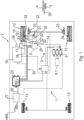
- Fig. 1 shows part of a braking system 1 for a towing vehicle 2, not shown in detail.
- the towing vehicle 2 is, for example, an agricultural utility vehicle, in particular a tractor.
- the braking system 1 in particular fulfils a parking or continuous braking function ("parking brake function") of wheels 13 of the towing vehicle 2 and of a Fig. 1 merely indicated trailer brake 3 of a trailer vehicle 4.
- parking brake function a parking or continuous braking function
- the functions described in more detail below can be part of a tractor braking system platform. This ensures the safe operation of the braking system 1 in various failure scenarios.
- the braking system 1 comprises an electronically controllable parking brake module in the form of a pneumatic valve arrangement 5, the details of which are described by Fig. 2 and Fig. 3 are shown.
- the pneumatic valve arrangement 5 comprises a first 3/2-solenoid directional valve designed as a control valve 6, a second 3/2-solenoid directional valve designed as a redundant valve 7, a pressure-controlled shuttle valve 8, a 3/2-solenoid directional valve designed as a brake valve 10 and a check valve 12.
- a towing vehicle relay valve 11 and a pressure sensor 15 are arranged downstream of the pneumatic valve arrangement 5.
- the control valve 6 and the redundant valve 7 of the parking brake module 5 are supplied with pneumatic pressure medium in the form of compressed air on the input side via a supply line 14 and via the check valve 12 from a pressure medium source 9.
- the towing vehicle relay valve 11 is also supplied with compressed air on the input side via the supply line 14 and via the check valve 12 from the pressure medium source 9.
- the pressure medium source 9 may comprise a compressor 9.1, which is driven by a not shown drive machine or by a motor (e.g. an internal combustion engine or an electric motor) of the towing vehicle 2 when an ignition of the towing vehicle 2 is switched on.
- the control valve 6 and the redundancy valve 7 are connected in a pneumatic parallel circuit on the input side to the pressure medium source 9 via the supply line 14 and the check valve 12.
- the shuttle valve 8 is connected on the input side to an output of the control valve 6 and the redundancy valve 7.
- the shuttle valve 8 is connected to an input of the brake valve 10 and via a connecting line 17 to a first input 18 (control pressure input) of a trailer control valve system 16.
- the higher pressure of the two valves 6, 7 can thus be output via the output of the shuttle valve 8 in the direction of the brake valve 10 and the first input 18 of the trailer control valve system 16.
- a control pressure input 19 of the relay valve 11 is connected to an output of the brake valve 10.
- a supply pressure input 20 of the relay valve 11 is connected to the pressure medium source 9 via the check valve 12 and the supply line 14.
- a pressure output 21 of the relay valve 11 is connected to two brake cylinders 23 for actuating a parking brake 24 via a brake cylinder line 22.
- the pressure sensor 15 is arranged in the brake cylinder line 22 and measures the pressure prevailing therein, which can be regarded as representative of a pressure within the brake cylinders 23.
- the pressure sensor 15 transmits the measured pressure to an electronic control unit 25 of the brake system 1.
- the electronic control unit 25 is also connected to the control valve 6, to the redundancy valve 7 and to the brake valve 10 via electronic control lines 35.
- Fig. 2 only one of the electronic control lines is provided with a reference symbol.
- the electronic control lines 35 can run in the area of the pneumatic valve arrangement 5, in particular in and/or on a valve block 28 described in more detail below.
- control valve 6 and the redundancy valve 7 are identical parts, but this is not mandatory.
- the brake valve 10 can also be constructed in the same way as the control valve 6 and/or the redundancy valve 7.
- a valve slide of the control valve 6 and the redundancy valve 7 is pre-tensioned in a closed switching position ("normally closed") by a spring element in a valve housing (not shown), which is Fig. 2 shown closed state of the control valve 6 and the redundancy valve 7.
- control valve 6 and the redundancy valve 7 are in the closed state, then no compressed air from the pressure medium source 9 is directed via the control valve 6 and the redundancy valve 7 in the direction of the shuttle valve 8, the brake valve 10 arranged further downstream and a towing vehicle control pressure outlet 32 described below, as well as in the direction of the towing vehicle relay valve 11 arranged further downstream.
- no control pressure is present at the control pressure inlet 19 of the relay valve 11, as a result of which the relay valve 11 does not convey any compressed air that is present at the supply pressure inlet 20 into the brake cylinder line 22 via the pressure outlet 21.
- the brake cylinders 23 are not filled with compressed air, as a result of which no deactivation pressure is built up in the brake cylinders 23, so that the parking locks 24 are or remain activated.
- the wheels 13 of the motor vehicle 2 are or remain locked by the parking locks 24.
- the control valve 6 and the redundancy valve 7 have electromagnets EM1 that can be energized so that the valve slides are moved from the closed switching position to an open switching position, which corresponds to an open state of the control valve 6 and the redundancy valve 7.
- the electromagnets EM1 are energized by or at least controlled by the electronic control unit 25.
- compressed air from the pressure medium source 9 is passed through the control valve 6 and the redundancy valve 7 and can be fed to the control pressure inlet 19 of the relay valve 11 via the shuttle valve 8 and the brake valve 10 arranged further downstream and the towing vehicle control pressure outlet 32.
- the pressure of the redundancy valve 7 can continue to be used, provided that the redundancy valve 7 is not has failed. If the redundancy valve 7 fails, the pressure of the control valve 6 can still be used, provided that the control valve 6 has not failed.
- a valve slide of the brake valve 10 is held within its valve housing by a spring element in a Fig. 2 shown open switching position ("normally open"), which corresponds to an open state of the brake valve 10.
- the brake valve 10 When the brake valve 10 is in the open state, compressed air that has been passed from the pressure medium source 9 via the open control valve 6 or the open redundant valve 7 and the shuttle valve 8 is fed via the brake valve 10 to the control pressure inlet 19 of the towing vehicle relay valve 11.
- the towing vehicle relay valve 11 feeds compressed air that is present at the supply pressure inlet 20 via the pressure outlet 21 into the brake cylinder line 22. Consequently, the brake cylinders 23 are filled with compressed air, whereby a deactivation pressure is built up in the brake cylinders 23 so that the parking locks 24 are deactivated.
- the wheels 13 of the towing vehicle 2 are then no longer locked by the parking locks 24.
- the electronic control unit 25 can control the energization of an electromagnet EM2 of the brake valve 10 in such a way that the valve slide of the brake valve 10 is moved from the open switching position to a closed switching position, which corresponds to a closed state of the brake valve 10.
- compressed air can escape from the brake cylinders 23 via the towing vehicle relay valve 11 and the brake valve 10 into a pressureless environment U, so that the deactivation pressure is reduced and the parking lock 24 is activated.
- the wheels 13 of the towing vehicle 2 are then locked.
- the valve arrangement 5 has an inverting switching characteristic.
- the parking locks 24 of the towing vehicle 2 are actuated when no pressure is output via the towing vehicle relay valve 11, and released when a sufficiently high pressure is output via the towing vehicle relay valve 11, which leads to the deactivation pressure within the brake cylinders 23.
- the pneumatic valve arrangement 5 enables a test function of the parking brake 24, according to which a driver of the towing vehicle 2 wants to check whether the full vehicle combination of towing vehicle 2 and trailer vehicle 4 can be held on an incline using only the parking brakes 24 of the towing vehicle 2.
- the driver can activate this function via the human-machine interface HMI in the cabin, whereby a brake test request is transmitted to the electronic control unit 25.
- the electronic control unit 25 controls the electromagnets EM1 of the control valve 6 and the redundancy valve 7 in such a way that the control valve 6 and the redundancy valve 7 are placed in the open state, so that pressure is applied to the first input 18 of the trailer control valve system and the trailer brake 3 remains released.
- the trailer brake 3 of the trailer vehicle therefore also has an inverted switching characteristic.
- the trailer brake 3 is not actuated or released when pressure is applied to the first input 18 of the trailer control valve system 16, and is actuated or applied when no pressure is applied to the first input 18 of the trailer control valve system 16.
- the electronic control unit 25 controls the electromagnet EM2 of the brake valve 10 in such a way that the brake valve 10 is placed in the closed state.
- the pressure in the spring brake cylinders 23 of the towing vehicle 2 is released via the brake valve 10 into the pressure-free environment U and the parking brakes 24 are activated so that braking is carried out by means of the towing vehicle 2.
- Fig. 1 shows that the electronic control unit 25 of the braking system 1 can be connected to an electronic (main) control unit 27 of the towing vehicle 2 via a CAN BUS 26.
- the electronic (main) control unit 27 of the towing vehicle 2 is connected in the embodiment shown in particular to a human-machine interface HMI in a driver's cabin of the towing vehicle 2.
- a driver or user of the towing vehicle 2 can operate the brake cylinders 23 of the towing vehicle 2 and/or the trailer brake 3 of the trailer vehicle 4. If the parking locks 24 are to be operated or activated in normal operation, ie when the electronic Control unit 25 is in an active state, then the control valve 6 and the redundancy valve 7 are deactivated, i.e.
- Fig. 2 and 3 show that the pneumatic valve arrangement 5 comprises a valve block 28 which has a supply pressure inlet 29, a towing vehicle supply pressure outlet 30, a trailer vehicle supply pressure outlet 31, a towing vehicle control pressure outlet 32 and a trailer vehicle control pressure outlet 33.
- the supply pressure inlet 29, the towing vehicle supply pressure outlet 30, the towing vehicle control pressure outlet 32, the trailer vehicle supply pressure outlet 31 and the trailer vehicle control pressure outlet 33 are arranged on the same lateral outer surface 34 of the valve block 28.
- the valve block is, for example, cuboid-shaped with four lateral outer surfaces 34, wherein the connections 29 to 33 are arranged on the same lateral outer surface 34.
- the control valve 6, the redundancy valve 7 and the brake valve 10 are in the embodiment according to Fig. 3 arranged next to one another on an upper outer surface 40 of the cuboid-shaped valve block 28 and fastened there with the valve block 28.
- the valve block 28 forms channels or pneumatic lines in its interior which connect the connections 29 to 33 and the valves 6 to 8 as well as 10 and 12 with one another.
- the supply pressure inlet 29 is connected upstream via the supply line 14 to the compressed air source 9. Downstream, the supply pressure inlet 29 - in particular within the valve block 28 - is connected via the check valve 12 to the towing vehicle supply pressure outlet 30. In the opposite flow direction, the check valve 12 separates the towing vehicle supply pressure outlet 30 from the supply pressure inlet 29.
- an inlet of the check valve 12 is connected to the supply pressure inlet 29 and an outlet of the check valve 12 to the towing vehicle supply pressure outlet 30.
- the check valve 12 causes compressed air coming from the compressed air source 9 to flow via the supply pressure inlet 29 and the check valve 12 to the towing vehicle supply pressure outlet 30.
- compressed air coming from the towing vehicle supply pressure outlet 30 is prevented from flowing via the check valve 12 to the supply pressure inlet 29.
- the trailer vehicle supply pressure outlet 31 is connected upstream to the supply pressure inlet 29, bypassing the check valve 12. Downstream, the trailer supply pressure output is connected to a supply pressure inlet 39 of the trailer control valve system 16 for the trailer brake 3 of the trailer 4 which is towed by the towing vehicle 2.
- the supply pressure inlet 29 is also connected to the control valve 6 and to the redundancy valve 7 via the check valve 12.
- the brake valve 10 is connected upstream on the one hand via the shuttle valve 8 to the control valve 6 and to the redundancy valve 7. Downstream, the brake valve 10 is connected to the towing vehicle control pressure outlet 32.
- the towing vehicle supply pressure outlet 30 is in turn connected according to Fig. 1 connected downstream to the supply pressure inlet 20 of the towing vehicle relay valve 11 for actuating the brake cylinder 23 of the towing vehicle 2.
- compressed air from the compressed air source 9 can flow via the control valve 6 or the redundancy valve 7 (depending on which air pressure is higher, one of the two compressed air flows is passed via the shuttle valve 8) and downstream via the brake valve 10 to the towing vehicle control pressure outlet 32.
- the towing vehicle control pressure output 32 is connected to the control pressure input 19 of the towing vehicle relay valve 11, so that the towing vehicle relay valve 11 can be used to pressurize the brake cylinders 23 and thus also to actuate the parking brakes 24 can be controlled. Furthermore, the trailer control pressure output 33 is also connected upstream via the shuttle valve 8 to the control valve 6 or the redundancy valve 7, so that the higher air pressure is also present at the trailer control pressure output 33. Downstream, the trailer control pressure output 33 is connected to the first pressure input 18 of the trailer control valve system 16, in particular to pressurize a relay valve of the trailer control valve system 16 for controlling the trailer brake 3.
- the connections described above can be implemented by channels that run within the valve block.
- the check valve 12 can also be integrated into the valve block 28.
- the electronic control unit 25 controls the electromagnets EM1 of the control valve 6 and the redundancy valve 7 in such a way that the control valve 6 and the redundancy valve 7 are placed in the closed state, so that the trailer vehicle control pressure output 33 is connected to the pressure-free environment U via the control valve 6 or the redundancy valve 7. Furthermore, the electronic control unit 25 controls the electromagnet EM2 of the brake valve 10 such that the brake valve 10 is placed in the closed state, so that the towing vehicle control pressure output 32 is also connected to the unpressurized environment U.
- a quick exhaust valve 36 is provided, which is integrated into the towing vehicle relay valve 11.
- the quick exhaust valve 35 is of the single-line type and can be provided, similar to a check valve, with a first inlet (connected to the supply pressure inlet 20 of the towing vehicle relay valve 11) and a second inlet (connected to the two brake cylinders 23) and a third inlet (connected to the unpressurized environment U).
- the venting of the quick exhaust valve 36 is closed as long as the first connection is under pressure. However, as soon as the first connection is depressurized, the pressure at the second connection opens the passage between the second connection and the third connection (outlet), so that the outlet of the quick exhaust valve 36 is vented.
Landscapes
- Engineering & Computer Science (AREA)
- Transportation (AREA)
- Mechanical Engineering (AREA)
- Braking Systems And Boosters (AREA)
- Valves And Accessory Devices For Braking Systems (AREA)
Abstract
Die Erfindung betrifft ein pneumatisches Ventilsystem (5) für ein Bremssystem eines Zugfahrzeugs. Das pneumatische Ventilsystem (5) umfasst einen Ventilblock (28), der einen Versorgungsdruckeingang (29), einen Zugfahrzeug-Versorgungsdruckausgang (30) und einen Zugfahrzeug-Steuerdruckausgang (32) aufweist, sowie ein Steuerventil (6), ein Redundanzventil (7) und ein Bremsventil (10). Das pneumatisches Ventilsystem (5) ermöglicht durch Verbindungen der Ventile sowie des Versorgungsdruckausgangs und Ausgänge miteinander auf sehr kompakte und stabile Weise insbesondere eine redundante Druckversorgung eines Bremszylinders einer Feststellbremse des Zugfahrzeugs.
Description
- Die Erfindung betrifft ein pneumatisches Ventilsystem für ein Bremssystem eines Zugfahrzeugs.
- Die
JP 2004217009 A2 - Eine Aufgabe der vorliegenden Erfindung kann darin gesehen werden, eine redundante Druckversorgung in einem pneumatischen Bremssystem auf besonders kompakte und stabile Weise bereitzustellen. Die Aufgabe wird gelöst durch die Gegenstände der unabhängigen Patentansprüche. Vorteilhafte Ausführungsformen sind Gegenstand der Unteransprüche, der folgenden Beschreibung sowie der Figuren.
- Die vorliegende Erfindung schlägt eine Ventilstruktur bzw. eine Ventilanordnung für ein Steuerungssystem einer pneumatischen Parksperre vor. Die Ventilstruktur ermöglicht über ein Redundanzventil eine redundante und damit sichere Druckluftversorgung eines Bremszylinders einer Parksperre, wenn das Steuerventil ausfallen sollte. Dazu notwendige Ventile, Verbindungen bzw. Leitungen und Anschlüsse (Eingänge und Ausgänge) können insbesondere in oder an einem Ventilblock angeordnet sein. Diese Integration in einem Ventilblock bietet eine kompakte Bauweise und erfordert lediglich eine Befestigungsmöglichkeit für den Ventilblock (mit entsprechender Festigkeit des Ventilblocks). Es müssen nicht länger für jedes der Ventile eine eigene Halterung im Fahrzeug angebracht werden. Dies erspart weiteren Bauraum, da nicht länger die Abmessungen der einzelnen Ventile und deren erforderliche Befestigungsmöglichkeiten ausschlaggebend sind und im Vergleich zur Summe der Einzelgeräte eine kompaktere Bauweise möglich ist. Weiterhin wird die Stabilität im Vergleich zu einzelnen Ventile erhöht, die meist nicht stabil genug sind, um zusammen mit anderen Geräten befestigt zu werden (Bruchgefahr).
- In diesem Sinne wird erfindungsgemäß ein pneumatisches Ventilsystem für ein Bremssystem eines Zugfahrzeugs bereitgestellt. Das pneumatische Ventilsystem umfasst einen Ventilblock, der einen Versorgungsdruckeingang, einen Zugfahrzeug-Versorgungsdruckausgang und einen Zugfahrzeug-Steuerdruckausgang aufweist. Weiterhin umfasst das pneumatische Ventilsystem ein als Steuerventil ausgebildetes erstes Wegeventil, ein als Redundanzventil ausgebildetes zweites Wegeventil und ein als Bremsventil ausgebildetes drittes Wegeventil. Der Ventilblock bildet insbesondere in seinem Inneren Kanäle, welche den Versorgungsdruckeingang mit den Wegeventilen, mit dem Zugfahrzeug-Versorgungsdruckausgang und mit dem Zugfahrzeug-Steuerdruckausgang sowie mit äquivalenten Ausgängen für ein weiter unten beschriebenes Anhängersteuerventilsystem verbinden. Die Wegeventile sind insbesondere in dem Ventilblock oder an einer äußeren Oberfläche des Ventilblocks angeordnet. Auch der Versorgungsdruckeingang und die Versorgungs- sowie Steuerdruckausgänge sind insbesondere an einer äußeren Oberfläche des Ventilblocks angeordnet. Der Ventilblock kann beispielsweise durch ein gegossenes Bauteil gebildet werden.
- Über den Versorgungsdruckeingang kann dem pneumatischen Ventilsystem Versorgungsdruckluft zugeführt werden. Über die Versorgungsdruckausgänge kann die Versorgungsdruckluft in Richtung wenigstens eines Bremszylinders einer Feststellbremse des Zugfahrzeugs oder einer Anhängerbremse zugeführt werden. Unter "Versorgungsdruckluft" ist insbesondere Luft zu verstehen, die unter einem ausreichend hohen Betätigungsdruck steht, um in dem Bremszylinder der Feststellbremse des Zugfahrzeugs einen ausreichend hohen Deaktivierungsdruck aufzubauen, sodass die Feststellbremse des Zugfahrzeugs deaktiviert wird, wodurch die Feststellbremse ein Rad des Zugfahrzeugs nicht festsetzt. Weiterhin kann die Versorgungsdruckluft dazu genutzt werden, um die Anhängerbremse zu betätigen (direkt oder invers). Über die Steuerluftausgänge kann das pneumatische Ventilsystem Steuerluft ausgeben, insbesondere an ein Zugfahrzeug-Relaisventil oder an das Anhängersteuerventilsystem. Unter "Steuerluft" ist insbesondere Luft zu verstehen, die unter einem ausreichend hohen Steuerdruck steht, um einen Ventilschieber des Zugfahrzeug-Relaisventils des Bremssystems des Zugfahrzeugs oder des Anhängersteuerventilsystems zu verschieben. Der Steuerdruck der Steuerluft ist insbesondere geringer als ein Versorgungsdruck, unter dem die Versorgungsdruckluft steht. Der Steuerdruck reicht insbesondere nicht dazu aus, um in dem Bremszylinder den Deaktivierungsdruck aufzubauen.
- Der Versorgungsdruckeingang ist dazu eingerichtet mit einer Druckluftquelle des Bremssystems verbunden zu werden. Unter dem Merkmal "verbunden" ist insbesondere zu verstehen, dass die jeweils miteinander verbundenen Elemente pneumatisch leitend miteinander verbunden sind, d.h. dass Druckluft von dem einen Element zu dem anderen Element strömen kann und ggfs. umgekehrt. Die Druckmittelquelle ist dazu eingerichtet, unter Druck stehende Druckluft zu bevorraten. Die Druckmittelquelle (z.B. ein Tank oder ein Akkumulator) ist dazu eingerichtet, die bevorratete Druckluft auszugeben, um den Bremszylinder des Zugfahrzeugs und/oder die Anhängerbremse des von dem Zugfahrzeug gezogenen Anhängefahrzeugs zu betätigen. Wenn die Zündung des Zugfahrzeugs eingeschaltet ist, kann ein Antriebsmotor des Zugfahrzeugs eine Befüllung der Druckmittelquelle bewirken, z.B. indem ein Kompressor angetrieben wird, der Luft ansaugt, verdichtet und der Druckmittelquelle zuführt.
- Das Bremsventil ist einerseits, insbesondere stromaufwärts, über ein Wechselventil mit dem Steuerventil und mit dem Redundanzventil sowie andererseits, insbesondere stromabwärts, mit dem Zugfahrzeug-Steuerdruckausgang verbunden. Der Versorgungsdruckeingang ist mit dem Steuerventil und mit dem Redundanzventil verbunden, sodass Druckluft aus der Druckluftquelle über das Steuerventil oder das Redundanzventil und stromabwärts über das Bremsventil zu dem Zugfahrzeug-Steuerdruckausgang strömen kann. Über das Redundanzventil kann auch dann noch Druckluft strömen und über das Wechselventil sowie das Bremsventil an den Zugfahrzeug-Steuerdruckausgang geleitet werden, wenn eine Steuerung des Steuerventils ausfällt, sodass über das Steuerventil keine Druckluft strömt. Somit wird eine Redundante Steuerung der Feststellbremse über den Zugfahrzeug-Steuerdruckausgang ermöglicht.
- Der Versorgungsdruckeingang ist weiterhin mit dem Zugfahrzeug-Versorgungsdruckausgang verbunden. Ferner ist der Zugfahrzeug-Versorgungsdruckausgang dazu eingerichtet, mit einem Versorgungsdruckeingang eines Zugfahrzeug-Relaisventils zur Betätigung eines Bremszylinders des Zugfahrzeugs verbunden zu werden. Durch die Verbindungsmöglichkeit mit dem Zugfahrzeug-Relaisventil können kleine Vorsteuerventile zur Steuerung des externen Relais anstelle von Standardventilen mit großem Durchflussdurchmesser verwendet werden, was eine verbesserte Verpackung und Kostenreduzierung ermöglicht. Außerdem ist der Zugfahrzeug-Steuerdruckausgang dazu eingerichtet, mit einem Steuerdruckeingang des Zugfahrzeug-Relaisventils verbunden zu werden. Somit kann das pneumatische Ventilsystem an seinem Ventilblock in besonders kompakter und stabiler Weise alle Anschlüsse bereitstellen, die notwendig sind, um ein Relaisventil zur Betätigung eines Bremszylinders mit Versorgungsdruckluft und Steuerluft zu versorgen.
- Im Falle eines Bruches oder Risses einer Verbindungsleitung zwischen dem Anhängefahrzeug-Versorgungsdruckausgang und einem Versorgungsdruckeingang des Anhängersteuerventilsystems oder einer anderen mit dem Anhängersteuerventilsystem verbundenen Leitung kann dies zu einer Leckage in der Druckluftversorgung der Bremszylinder des Zugfahrzeugs führen. Infolgedessen kann der Luftdruck, der an dem Zugfahrzeug-Versorgungsdruckausgang anliegt, auf einen derart niedrigen Wert fallen, der zu einer automatischen Aktivierung der Feststellbremsanlage führen würde. Um dies zu vermeiden kann ein Rückschlagventil den Druck im Feststellbremssystem des Zugfahrzeugs aufrechterhalten, so dass das Zugfahrzeug für kurze Zeit - ohne dass die Feststellbremse aktiviert ist - weiterfahren kann, bis ein sicherer Halt des Fahrzeugs möglich ist. In diesem Sinne ist gemäß einer weiteren Ausführungsform vorgesehen, dass der Ventilblock ein Rückschlagventil aufweist, welches den Versorgungsdruckeingang mit dem Steuerventil und dem Redundanzventil verbindet, sodass Druckluft aus der Druckluftquelle über das Steuerventil oder das Redundanzventil und stromabwärts über das Bremsventil zu dem Zugfahrzeug-Steuerdruckausgang strömen kann.
- Weiterhin verbindet das Rückschlagventil den Versorgungsdruckeingang mit dem Zugfahrzeug-Versorgungsdruckausgang und trennt in umgekehrter Strömungsrichtung den Zugfahrzeug-Versorgungsdruckausgang von dem Versorgungsdruckeingang. Insbesondere ist ein Eingang des Rückschlagventils mit dem Versorgungsdruckeingang und ein Ausgang des Rückschlagventils mit dem Zugfahrzeug-Versorgungsdruckausgang verbunden. Das Rückschlagventil bewirkt, dass aus der Druckluftquelle kommende Druckluft über den Versorgungsdruckeingang des Ventilblocks und das Rückschlagventil zu dem Zugfahrzeug-Versorgungsdruckausgang des Ventilblocks strömen kann. Dahingegen wird insbesondere von dem Zugfahrzeug-Versorgungsdruckausgang kommende Druckluft daran gehindert, über das Rückschlagventil zu dem Versorgungsdruckeingang zu strömen. Das Gleiche gilt für Druckluft, die aus der Richtung des Steuerventils und des Redundanzventils kommt. Über das Redundanzventil kann auch dann noch Druckluft strömen und über das Wechselventil sowie das Bremsventil an den Zugfahrzeug-Steuerdruckausgang geleitet werden, wenn eine Steuerung des Steuerventils ausfällt, sodass über das Steuerventil keine Druckluft strömt. Somit wird eine Redundante Steuerung der Feststellbremse über den Zugfahrzeug-Steuerdruckausgang ermöglicht. Das Rückschlagventil ermöglicht weiterhin eine Einbindung des pneumatischen Ventilsystems in einen Druckkreislauf ("Kreislauf 3") einer Bremsanlage zusammen mit der Versorgung des Anhängersteuerventils, da der Feststellbremskreis über das Rückschlagventil in der Versorgung gesichert ist. Das Rückschlagventil ist insbesondere zwischen dem Versorgungsdruckeingang einerseits und dem Zugfahrzeug-Versorgungsdruckausgang sowie dem Steuerventil und dem Redundanzventil andererseits angeordnet.
- Gemäß einer weiteren Ausführungsform ist vorgesehen, dass der Ventilblock einen Anhängefahrzeug-Versorgungsdruckausgang und einen Anhängefahrzeug-Steuerdruckausgang aufweist, wobei der Anhängefahrzeug-Versorgungsdruckausgang unter Umgehung des Rückschlagventils mit dem Versorgungsdruckeingang verbunden ist, und wobei der Anhängefahrzeug-Versorgungsdruckausgang dazu eingerichtet ist, mit einem Versorgungsdruckeingang eines Anhängersteuerventilsystems für die Anhängerbremse des Anhängefahrzeugs verbunden zu werden, welches von dem Zugfahrzeug gezogen wird. Der Anhängefahrzeug-Steuerdruckausgang ist einerseits - insbesondere stromaufwärts - über das Wechselventil mit dem Steuerventil und mit dem Redundanzventil verbunden, und andererseits dazu eingerichtet, mit einem Steuerdruckeingang des Anhängersteuerventilsystems verbunden zu werden (insbesondere stromabwärts. Über das Redundanzventil kann in dieser Ausführungsform auch dann noch Druckluft strömen und über das Wechselventil sowie das Bremsventil an den Anhängefahrzeug-Steuerdruckausgang geleitet werden, wenn eine Steuerung des Steuerventils ausfällt, sodass über das Steuerventil keine Druckluft strömt. Somit ist auch für die Anhängerbremse eine Redundanz gegeben. Durch die zusätzliche Integration des Anhängefahrzeug-Versorgungsdruckausgangs und des Anhängefahrzeug-Steuerdruckausgangs in den Ventilblock kann nochmals der Bauraum reduziert werden, wobei gleichzeitig die Befestigungsstabilität der Ventile erhöht werden kann.
- Insbesondere alle pneumatischen Anschlüsse (Eingänge und Ausgänge) können auf derselben Seite des Ventilblocks platziert werden. Dies ermöglicht nochmals kleinere Einbauräume im Vergleich zum Einbau von Einzelkomponenten. In diesem Sinne ist gemäß einer weiteren Ausführungsform vorgesehen, dass der Versorgungsdruckeingang, der Zugfahrzeug-Versorgungsdruckausgang, der Zugfahrzeug-Steuerdruckausgang, der Anhängefahrzeug-Versorgungsdruckausgang und der Anhängefahrzeug-Steuerdruckausgang auf ein- und derselben Außenfläche des Ventilblocks angeordnet sind.
- Die Steuerung insbesondere des Steuerventils des Redundanzventils und des Bremsventils erfolgt bevorzugt elektronisch, um letztendlich auch eine elektronische Steuerung der Feststellbremse des Zugfahrzeugs und der Anhängerbremse des Anhängefahrzeugs zu ermöglichen. Diese elektronische Steuerung erfordert keine zusätzlichen Kabel oder Leitungen oder Ventile innerhalb einer Fahrerkabine des Zugfahrzeugs. Dies reduziert den Montageaufwand und ermöglicht eine Geräuschreduzierung. Das Ventilpaket wird dabei über ein externes Steuergerät angesteuert, das über CAN-Bus oder bereits vorhandene Verkabelung aus der Kabine mit dem Ventilsystem zur Aktivierung der Feststellbremse kommuniziert. Weiterhin wird eine Verwendung für fahrerunabhängige Assistenz- und Sicherheitsfunktionen ermöglicht, wie sie für autonome Fahrzeuge benötigt werden. In diesem Sinne ist gemäß einer Ausführungsform vorgesehen, dass das pneumatische Ventilsystem weiterhin eine elektronische Steuerungseinheit umfasst, die über elektronische Steuerungsleitungen mit dem Steuerventil, dem Redundanzventil und dem Bremsventil verbunden ist.
- Das Steuerventil, das Redundanzventil und das Bremsventil sind Magnetventile, die jeweils einen Elektromagneten aufweisen. Die elektronische Steuerungseinheit ist dazu eingerichtet, die Elektromagnete derart zu steuern, dass das Steuerventil und das Redundanzventil aus einem mechanisch vorgespannten geschlossenen Zustand in einen geöffneten Zustand und umgekehrt versetzt werden, und das Bremsventil aus einem mechanisch vorgespannten geöffneten Zustand in einen geschlossenen Zustand und umgekehrt versetzt wird. Mit anderen Worten sind das Steuerventil und das Redundanzventil insbesondere in einem geschlossenen Zustand mechanisch vorgespannt (""normally closed). Wenn sich das Steuerventil und das Redundanzventil in dem geschlossenen Zustand befinden, dann strömt keine Druckluft aus der Druckluftquelle über das Steuerventil und das Redundanzventil zu dem Wechselventil. Weiterhin kann insbesondere von dem Wechselventil kommende Druckluft über das Steuerventil und das Redundanzventil in eine drucklose Umgebung entweichen, wenn sich das Steuerventil und das Redundanzventil in dem geschlossenen Zustand befinden.
- Das Steuerventil und das Redundanzventil können entgegen der mechanischen Vorspannung in einen geöffneten Zustand versetzt werden. Insbesondere weisen das Steuerventil und das Redundanzventil dazu einen Elektromagneten auf, der bestromt werden kann, sodass ein Magnetfeld aufgebaut wird, welches einen Ventilschieber des Steuerventils und des Redundanzventils entgegen der mechanischen Vorspannung in eine geöffnete Schaltstellung verschiebt, was einer geöffneten Stellung des Steuerventils und des Redundanzventils entspricht. Die Bestromung der Elektromagnete kann insbesondere durch eine elektronische Steuerungseinheit des Bremssystems erfolgen. Die elektronische Steuerungseinheit kann dazu über elektronische Steuerleitungen mit den Elektromagneten des Steuerungsventils und des Redundanzventils verbunden sein. Wenn sich das Steuerventil und das Redundanzventil in dem geöffneten Zustand befinden, dann strömt Druckluft aus der Druckluftquelle über das Steuerventil und das Redundanzventil zu dem Wechselventil.
- Das Bremsventil ist insbesondere in einem geöffneten Zustand mechanisch ("normally open") vorgespannt. Wenn sich das Bremsventil in dem geöffneten Zustand befindet, dann strömt von dem Wechselventil kommende Druckluft über das Bremsventil zu dem Zugfahrzeug-Steuerdruckausgang. Das Bremsventil kann entgegen der mechanischen Vorspannung in einen geschlossenen Zustand versetzt werden. Insbesondere weist das Bremsventil dazu einen Elektromagneten auf, der bestromt werden kann, sodass ein Magnetfeld aufgebaut wird, welches einen Ventilschieber des Bremsventils entgegen der mechanischen Vorspannung in eine geschlossene Schaltstellung verschiebt, was einer geschlossenen Stellung des Bremsventils entspricht. Wenn sich das Bremsventil in dem geschlossenen Zustand befinden, dann kann von dem Zugfahrzeug-Steuerdruckausgang kommende Druckluft über das Bremsventil direkt in die drucklose Umgebung entweichen.
- Weiterhin kann das Ventilsystem eine Testfunktion der Feststellbremse ermöglichen, gemäß welcher der Fahrer prüfen möchte, ob das volle Fahrzeuggespann aus Zugfahrzeug und Anhängefahrzeug nur mit den Feststellbremsen des Zugfahrzeugs an einer Steigung gehalten werden kann. Über eine Schnittstelle in der Kabine kann der Fahrer diese Funktion aktivieren. Das Steuerventil und das Redundanzventil bleiben dazu aktiviert, d.h. sie verbleiben in ihrem geöffneten Zustand, sodass die Anhängerbremse weiterhin gelöst bleibt. Das Bremsventil wird in die geschlossene Position geschaltet. Dadurch wird der Druck in den Federspeicherbremszylindern des Zugfahrzeugs abgelassen und die Feststellbremsen aktiviert, sodass eine Bremsung mittels des Zugfahrzeugs durchgeführt wird. In diesem Sinne ist gemäß einer weiteren Ausführungsform vorgesehen, dass die elektronische Steuerungseinheit nach Empfangen einer Bremstestanforderung dazu eingerichtet ist, die Elektromagnete des Steuerventils und des Redundanzventils derart zu steuern, dass das Steuerventil und das Redundanzventil in den geöffneten Zustand versetzt werden. Weiterhin ist die elektronische Steuerungseinheit nach Empfangen der Bremstestanforderung dazu eingerichtet, den Elektromagneten des Bremsventils derart zu steuern, dass das Bremsventil in den geschlossenen Zustand versetzt wird, sodass die Anhängerbremse deaktiviert und die Feststellbremse des Zugfahrzeugs aktiviert wird.
- Das pneumatische Ventilsystem kann zum einen in einen sogenannten unbetätigten Zustand versetzt werden. Dabei wird der Versorgungsdruckeingang durch das Luftversorgungssystem des Zugfahrzeugs mit Druckluft versorgt bzw. mit Druck beaufschlagt. Dadurch werden auch der Zugfahrzeug-Versorgungsdruckausgang und der Anhängefahrzeug-Versorgungsdruckausgang mit Druckluft versorgt bzw. mit Druck beaufschlagt. Der Zugfahrzeug-Steuerdruckausgang und der Anhängefahrzeug-Druckausgang hingegen werden nicht mit Druckluft versorgt bzw. nicht mit Druck beaufschlagt, indem das Steuerventil und das Redundanzventil in den geschlossenen Zustand versetzt werden. Durch eine invertierte Funktion der Bremszylinder und der Anhängerbremse ergibt sich dadurch eine aktive Feststellbremswirkung. In diesem Sinne ist gemäß einer weiteren Ausführungsform vorgesehen, dass die elektronische Steuerungseinheit dazu eingerichtet ist, die Elektromagnete des Steuerventils und des Redundanzventils derart zu steuern, dass das Steuerventil und das Redundanzventil in den geschlossenen Zustand versetzt werden, sodass keine Druckluft aus der Druckmittelquelle über das Steuerventil oder das Redundanzventil und stromabwärts zum einen zu dem Anhängefahrzeug-Steuerdruckausgang und zum anderen über das Bremsventil zu dem Zugfahrzeug-Steuerdruckausgang strömen kann, wodurch die Feststellbremse des Zugfahrzeugs und die Anhängerbremse aktiviert werden können.
- Zum anderen kann das pneumatische Ventilsystem in einen sogenannten betätigten Zustand versetzt werden. Dabei wird der Versorgungsdruckeingang durch das Luftversorgungssystem des Zugfahrzeugs mit Druckluft versorgt bzw. mit Druck beaufschlagt. Dadurch werden auch der Zugfahrzeug-Versorgungsdruckausgang und der Anhängefahrzeug-Versorgungsdruckausgang mit Druckluft versorgt bzw. mit Druck beaufschlagt. Der Zugfahrzeug-Steuerdruckausgang und der Anhängefahrzeug-Druckausgang werden mit Druckluft versorgt bzw. mit Druck beaufschlagt, indem das Steuerventil und das Redundanzventil in den geöffneten Zustand versetzt werden und das Bremsventil in seinem mechanisch vorgespannten geöffneten Zustand belassen wird. Durch die invertierte Funktion der Bremszylinder und der Anhängerbremse ergibt sich dadurch eine inaktive Feststellbremswirkung. In diesem Sinne ist gemäß einer weiteren Ausführungsform vorgesehen, dass die Elektromagnete des Steuerventils und des Redundanzventils derart zu steuern, dass das Steuerventil und das Redundanzventil in den geöffneten Zustand versetzt werden, sodass Druckluft aus der Druckmittelquelle über das Steuerventil oder das Redundanzventil und stromabwärts zum einen zu dem Anhängefahrzeug-Steuerdruckausgang und zum anderen über das Bremsventil zu dem Zugfahrzeug-Steuerdruckausgang strömen kann, wodurch die Feststellbremse des Zugfahrzeugs und die Anhängerbremse deaktiviert werden können.
- Weiterhin kann eine Vereinheitlichung von Bauteilen dahingehend vorgenommen werden, dass drei Mal dasselbe Magnetventil verwendet wird. In diesem Sinne ist gemäß einer weiteren Ausführungsform vorgesehen, dass es sich bei dem Steuerventil, bei dem Redundanzventil und bei dem Bremsventil um Gleichteile handelt. Der normal geschlossene Zustand (Steuerventil, Redundanzventil) und normal geöffnete Zustand (Bremsventil) kann dabei über mechanische Eigenschaften innerhalb des Ventilblocks realisiert werden.
- Ferner kann vorgesehen sein, dass alle drei Magnetventile betätigt werden, sobald die Feststellbremsanlage geschaltet wird, um das Anhängersteuerventil und die Federspeicherbremszylinder zu entlüften. In der Folge entlüftet entweder das Steuerventil oder das Redundanzventil den Steuerdruck für das Anhängersteuerventilsystem und das Bremsventil die Leitungen zur Betätigung des Relaisventils und damit der Federspeicherbremsen des Zugfahrzeugs. Der Vorteil liegt darin, dass vorhandene Ventile genutzt werden können, um das Ansprechverhalten des Systems zu erhöhen. In diesem Sinne ist gemäß einer weiteren Ausführungsform vorgesehen, dass die elektronische Steuerungseinheit dazu eingerichtet ist, die Elektromagnete des Steuerventils und des Redundanzventils derart zu steuern, dass das Steuerventil und das Redundanzventil in den geschlossenen Zustand versetzt werden, sodass der Anhängefahrzeug-Steuerdruckausgang über das Steuerventil oder das Redundanzventil mit einer drucklosen Umgebung verbunden wird. Weiterhin ist die elektronische Steuerungseinheit dazu eingerichtet, den Elektromagneten des Bremsventils derart zu steuern, dass das Bremsventil in den geschlossenen Zustand versetzt wird, sodass der Zugfahrzeug-Steuerdruckausgang mit der drucklosen Umgebung verbunden wird.
- Außerdem kann das Zugfahrzeug-Relaisventil zusammen mit einem Schnellentlüftungsventil verwendet werden. Um die Geschwindigkeit der Druckentlastung größerer Volumina (z.B. im Bereich der Federbremszylinder des Zugfahrzeugs) zu erhöhen, kann der Einsatz eines solchen Schnellentlüftungsventils von Vorteil sein. Das Schnellentlüftungsventil ist dazu eingerichtet, Druckluft aus dem Bremszylinder direkt in die drucklose Umgebung abzulassen. Das Schnellentlüftungsventil kann beispielsweise vom Einleitertyp sein. Insbesondere ist das Schnellentlüftungsventil zwischen einem Relaisventil und einem Bremszylinder der Parksperre des Zugfahrzeugs angeordnet oder innerhalb des genannten Relaisventils. Da Schnellentlüftungsventile große Luftdurchlässe bieten und die Möglichkeit besteht, diese Ventile in der Nähe der mit Druck beaufschlagten Volumen zu platzieren, ist eine schnelle Entlüftung möglich, ohne durch kleine Durchflussdurchmesser anderer Ventile oder lange Leitungen dazwischen eingeschränkt zu sein. In diesem Sinne ist gemäß einer weiteren Ausführungsform vorgesehen, dass ein Schnellentlüftungsventil mit dem Zugfahrzeug-Relaisventils verbunden ist, wobei das Schnellentlüftungsventil dazu eingerichtet ist, Druckluft aus dem Bremszylinder direkt in die drucklose Umgebung abzulassen.
- Im Folgenden werden Ausführungsbeispiele der Erfindung anhand der schematischen Zeichnung näher erläutert, wobei gleiche oder ähnliche Elemente mit dem gleichen Bezugszeichen versehen sind. Hierbei zeigt
- Fig. 1
- eine Draufsicht auf einen Teil eines Bremssystems für ein Zugfahrzeug und ein Anhängefahrzeug,
- Fig. 2
- Details einer erfindungsgemäßen pneumatischen Ventilanordnung des Bremssystems nach
Fig. 1 und - Fig. 3
- konstruktive Details der pneumatischen Ventilanordnung nach
Fig. 2 , -
Fig. 1 zeigt einen Teil eines Bremssystems 1 für ein nicht näher dargestelltes Zugfahrzeug 2. Bei dem Zugfahrzeug 2 handelt es sich beispielsweise um ein landwirtschaftliche Nutzfahrzeug, insbesondere um einen Traktor. Das Bremssystem 1 erfüllt insbesondere eine Feststell- bzw. Dauerbremsfunktion ("Parkbremsfunktion") von Rädern 13 des Zugfahrzeugs 2 sowie einer inFig. 1 lediglich angedeuteten Anhängerbremse 3 eines Anhängefahrzeugs 4. Die im Folgenden näher beschriebenen Funktionen können ein Teil einer Traktor-Bremssystem-Plattform sein. Diese gewährleistet den sicheren Betrieb des Bremssystems 1 bei verschiedenen Ausfallszenarien. - Das Bremssystem 1 umfasst ein elektronisch steuerbares Festellbremsmodul in Form einer pneumatischen Ventilanordnung 5, deren Einzelheiten durch
Fig. 2 und Fig. 3 gezeigt sind. Die pneumatische Ventilanordnung 5 umfasst ein als Steuerventil 6 ausgebildetes erstes 3/2-Magnet-Wegeventil, ein als Redundanzventil 7 ausgebildetes zweites 3/2-Magnet-Wegeventil, ein druckgesteuertes Wechselventil 8, ein als Bremsventil 10 ausgeführtes 3/2-Magnet-Wegeventil und ein Rückschlagventil 12. Stromabwärts der pneumatischen Ventilanordnung 5 sind ein Zugfahrzeug-Relaisventil 11 und ein Drucksensor 15 angeordnet. Das Steuerventil 6 und das Redundanzventil 7 des Feststellbremsmoduls 5 werden eingangsseitig über eine Versorgungsleitung 14 und über das Rückschlagventil 12 von einer Druckmittelquelle 9 mit pneumatischem Druckmittel in Form von Druckluft versorgt. Auch das Zugfahrzeug-Relaisventil 11 wird eingangsseitig über die Versorgungsleitung 14 und über das Rückschlagventil 12 von der Druckmittelquelle 9 mit Druckluft versorgt. Die Druckmittelquelle 9 kann einen Kompressor 9.1 umfassen, welcher von einer nicht gezeigten Antriebsmaschine bzw. von einem Motor (z.B. ein Verbrennungskraftmotor oder ein Elektromotor) des Zugfahrzeugs 2 angetrieben werden kann, wenn eine Zündung des Zugfahrzeugs 2 eingeschaltet ist. - Das Steuerventil 6 und das Redundanzventil 7 sind in einer pneumatischen Parallelschaltung jeweils eingangsseitig über die Versorgungsleitung 14 und das Rückschlagventil 12 mit der Druckmittelquelle 9 verbunden. Das Wechselventil 8 ist eingangsseitig mit jeweils einem Ausgang des Steuerventils 6 und des Redundanzventils 7 verbunden. Ausgangsseitig ist das Wechselventil 8 mit einem Eingang des Bremsventils 10 sowie über eine Verbindungsleitung 17 mit einem ersten Eingang 18 (Steuerdruckeingang) eines Anhängersteuerventilsystems 16 verbunden. Somit kann der jeweils höhere Druck der beiden Ventile 6, 7 über den Ausgang des Wechselventils 8 in Richtung des Bremsventils 10 und des ersten Eingangs 18 des Anhängersteuerventilsystems 16 ausgegeben werden.
- Ein Steuerdruckeingang 19 des Relaisventils 11 ist mit einem Ausgang des Bremsventils 10 verbunden. Ein Versorgungsdruckeingang 20 des Relaisventils 11 ist über das Rückschlagventil 12 und die Versorgungsleitung 14 mit der Druckmittelquelle 9 verbunden. Ein Druckausgang 21 des Relaisventils 11 ist über eine Bremszylinderleitung 22 mit zwei Bremszylindern 23 zur Betätigung jeweils einer Feststellbremse 24 verbunden. Der Drucksensor 15 ist in der Bremszylinderleitung 22 angeordnet und misst den darin vorherrschenden Druck, welcher als repräsentativ für einen Druck innerhalb der Bremszylinder 23 angesehen werden kann. Der Drucksensor 15 übermittelt den gemessenen Druck an eine elektronische Steuerungseinheit 25 des Bremssystems 1. Die elektronische Steuerungseinheit 25 ist weiterhin über elektronische Steuerungsleitungen 35 mit dem Steuerventil 6, mit dem Redundanzventil 7 und mit dem Bremsventil 10 verbunden. Der besseren Übersichtlichkeit halber ist in
Fig. 2 lediglich eine der elektronischen Steuerleitungen mit einem Bezugszeichen versehen. Die elektronischen Steuerleitungen 35 können im Bereich der pneumatischen Ventilanordnung 5 insbesondere in und/oder an einem weiter unten näher beschriebenen Ventilblock 28 verlaufen. - Bei dem Steuerventil 6 und bei dem Redundanzventil 7 handelt es sich in dem gezeigten Ausführungsbeispiel um Gleichteile, was jedoch nicht zwingend ist. Auch das Bremsventil 10 kann gleich aufgebaut sein wie das Steuerventil 6 und/oder das Redundanzventil 7. Ein Ventilschieber des Steuerventils 6 und des Redundanzventils 7 ist jeweils in einem nicht dargestellten Ventilgehäuse durch ein Federelement in einer geschlossenen Schaltstellung vorgespannt ("normally closed"), was einem durch
Fig. 2 gezeigten geschlossenen Zustand des Steuerventils 6 und des Redundanzventils 7 entspricht. Wenn sich das Steuerventil 6 und das Redundanzventil 7 in dem geschlossenen Zustand befinden, dann wird keine Druckluft aus der Druckmittelquelle 9 über das Steuerventil 6 und das Redundanzventil 7 in Richtung des Wechselventils 8, des weiter stromabwärts angeordneten Bremsventils 10 und eines weiter unten beschriebenen Zugfahrzeug-Steuerdruckausgangs 32 sowie in Richtung des weiter stromabwärts angeordneten Zugfahrzeug-Relaisventils 11 geleitet. Somit liegt kein Steuerdruck an dem Steuerdruckeingang 19 des Relaisventils 11 an, wodurch das Relaisventil 11 keine Druckluft, die an dem Versorgungsdruckeingang 20 anliegt, über den Druckausgang 21 in die Bremszylinderleitung 22 fördert. Folglich werden die Bremszylinder 23 nicht mit Druckluft gefüllt, wodurch in den Bremszylindern 23 kein Deaktivierungsdruck aufgebaut wird, sodass die Parksperren 24 aktiviert werden bzw. bleiben. Die Räder 13 des Kraftfahrzeugs 2 sind bzw. bleiben dann durch die Parksperren 24 festgestellt. - Das Steuerventil 6 und das Redundanzventil 7 weisen Elektromagnete EM1 auf, die bestromt werden können, sodass die Ventilschieber aus der geschlossenen Schaltstellung in eine geöffnete Schaltstellung verschoben werden, was einem geöffneten Zustand des Steuerventils 6 und des Redundanzventils 7 entspricht. Das Bestromen der Elektromagneten EM1 erfolgt durch die oder zumindest gesteuert von der elektronischen Steuerungseinheit 25. Wenn sich das Steuerventil 6 und das Redundanzventil 7 in dem geöffneten Zustand befinden, dann wird Druckluft aus der Druckmittelquelle 9 über das Steuerventil 6 und das Redundanzventil 7 geleitet und kann über das Wechselventil 8 sowie das weiter stromabwärts angeordnete Bremsventil 10 und den Zugfahrzeug-Steuerdruckausgang 32 dem Steuerdruckeingang 19 des Relaisventils 11 zugeführt werden. Wenn das Steuerventil 6 ausfällt, dann kann der Druck des Redundanzventils 7 weiter genutzt werden, sofern das Redundanzventil 7 nicht ausgefallen ist. Wenn das Redundanzventil 7 ausfällt, dann kann der Druck des Steuerventils 6 weiter genutzt werden, sofern das Steuerventil 6 nicht ausgefallen ist.
- Ein Ventilschieber des Bremsventils 10 ist innerhalb dessen Ventilgehäuse durch ein Federelement in einer durch
Fig. 2 gezeigten geöffneten Schaltstellung vorgespannt ("normally open"), was einem geöffneten Zustand des Bremsventils 10 entspricht. Wenn sich das Bremsventil 10 in dem geöffneten Zustand befinden, dann wird Druckluft, die aus der Druckmittelquelle 9 über das geöffnete Steuerventil 6 oder das geöffnete Redundanzventil 7 sowie das Wechselventil 8 geleitet worden ist, über das Bremsventil 10 dem Steuerdruckeingang 19 des Zugfahrzeug-Relaisventils 11 zugeführt. In diesem Fall fördert das Zugfahrzeug-Relaisventil 11 Druckluft, die an dem Versorgungsdruckeingang 20 anliegt, über den Druckausgang 21 in die Bremszylinderleitung 22. Folglich werden die Bremszylinder 23 mit Druckluft gefüllt, wodurch in den Bremszylindern 23 ein Deaktivierungsdruck aufgebaut wird, sodass die Parksperren 24 deaktiviert werden. Die Räder 13 des Zugfahrzeugs 2 sind dann nicht länger durch die Parksperren 24 festgestellt. - Die elektronische Steuerungseinheit 25 kann eine Bestromung eines Elektromagneten EM2 des Bremsventils 10 derart steuern, dass der Ventilschieber des Bremsventils 10 aus der geöffneten Schaltstellung in eine geschlossene Schaltstellung verschoben wird, was einem geschlossenen Zustand des Bremsventils 10 entspricht. Wenn sich das Bremsventil 10 in dem geschlossenen Zustand befindet, dann kann Druckluft aus den Bremszylindern 23 über das Zugfahrzeug-Relaisventil 11 und das Bremsventil 10 in eine drucklose Umgebung U entweichen, sodass der Deaktivierungsdruck abgebaut wird und die Parksperre 24 aktiviert wird. Die Räder 13 des Zugfahrzeugs 2 sind dann festgestellt. Man kann in diesem Zusammenhang davon sprechen, dass die Ventilanordnung 5 eine invertierende Schaltcharakteristik aufweist. Die Parksperren 24 des Zugfahrzeugs 2 werden betätigt, wenn über das Zugfahrzeug-Relaisventil 11 kein Druck ausgegeben wird, sowie gelöst, wenn über das Zugfahrzeug-Relaisventil 11 ein ausreichend hoher Druck ausgegeben wird, der zu dem Deaktivierungsdruck innerhalb der Bremszylinder 23 führt.
- Weiterhin ermöglicht die pneumatische Ventilanordnung 5 eine Testfunktion der Feststellbremse 24, gemäß welcher ein Fahrer des Zugfahrzeugs 2 prüfen möchte, ob das volle Fahrzeuggespann aus Zugfahrzeug 2 und Anhängefahrzeug 4 allein mit den Feststellbremsen 24 des Zugfahrzeugs 2 an einer Steigung gehalten werden kann. Über die Mensch-Maschine-Schnittstelle HMI in der Kabine kann der Fahrer diese Funktion aktivieren, wobei eine Bremstestanforderung an die elektronische Steuerungseinheit 25 übermittelt wird. Die elektronische Steuerungseinheit 25 steuert daraufhin die Elektromagneten EM1 des Steuerventils 6 und des Redundanzventils 7 derart, dass das Steuerventil 6 und das Redundanzventil 7 in den geöffneten Zustand versetzt werden, sodass an dem ersten Eingang 18 des Anhängersteuerventilsystem Druck anliegt und die Anhängerbremse 3 weiterhin gelöst bleibt.
- Auch die Anhängerbremse 3 des Anhängefahrzeugs weist somit eine invertierte Schaltcharakteristik auf. Die Anhängerbremse 3 wird nicht betätigt bzw. gelöst, wenn an dem ersten Eingang 18 des Anhängersteuerventilsystems 16 Druck anliegt, sowie betätigt bzw. angezogen, wenn an dem ersten Eingang 18 des Anhängersteuerventilsystems 16 kein Druck anliegt. Weiterhin steuert die elektronische Steuerungseinheit 25 den Elektromagneten EM2 des Bremsventils 10 derart, dass das Bremsventil 10 in den geschlossenen Zustand versetzt wird. Dadurch wird der Druck in den Federspeicherbremszylindern 23 des Zugfahrzeugs 2 über das Bremsventil 10 in die drucklose Umgebung U abgelassen und die Feststellbremsen 24 werden aktiviert, sodass eine Bremsung mittels des Zugfahrzeugs 2 durchgeführt wird.
-
Fig. 1 zeigt, dass die elektronische Steuerungseinheit 25 des Bremssystems 1 über einen CAN BUS 26 mit einer elektronischen (Haupt-)Steuerungseinheit 27 des Zugfahrzeugs 2 verbunden sein kann. Die elektronische (Haupt-)Steuerungseinheit 27 des Zugfahrzeugs 2 ist in dem gezeigten Ausführungsbeispiel insbesondere mit einer Mensch-Maschine-Schnittstelle HMI in einer Fahrerkabine des Zugfahrzeugs 2 verbunden. Mittels der Mensch-Maschine-Schnittstelle HMI kann ein Fahrer oder Nutzer des Zugfahrzeugs 2 die Bremszylinder 23 des Zugfahrzeugs 2 und/oder die Anhängerbremse 3 des Anhängefahrzeugs 4 bedienen. Wenn die Parksperren 24 im Normalbetrieb betätigt bzw. aktiviert werden sollen, d.h. wenn sich die elektronische Steuerungseinheit 25 in einem aktiven Zustand befindet, dann werden das Steuerventil 6 und das Redundanzventil 7 deaktiviert, d.h. in den geschlossenen Zustand versetzt, sodass die Bremszylinder 23 über das Relaisventil 11 sowie das deaktivierte Bremsventil 10 entlüftet werden können. Wenn das Bremsventil 10 deaktiviert ist, befindet es sich in dem geöffneten Zustand, sodass Druckmittel aus dem Bremszylinder 23 über das Zugfahrzeug-Relaisventil 11, das Bremsventil 10, das Wechselventil 8, das Steuerventil 6 und das Redundanzventil 7 in die drucklose Umgebung U entweichen kann. -
Fig. 2 und 3 zeigen, dass die pneumatische Ventilanordnung 5 einen Ventilblock 28 umfasst, der einen Versorgungsdruckeingang 29, einen Zugfahrzeug-Versorgungsdruckausgang 30, einen Anhängefahrzeug-Versorgungsdruckausgang 31, einen Zugfahrzeug-Steuerdruckausgang 32 und einen Anhängefahrzeug-Steuerdruckausgang 33 aufweist. In dem durchFig. 3 gezeigten Ausführungsbeispiel sind der Versorgungsdruckeingang 29, der Zugfahrzeug-Versorgungsdruckausgang 30, der Zugfahrzeug-Steuerdruckausgang 32, der Anhängefahrzeug-Versorgungsdruckausgang 31 und der Anhängefahrzeug-Steuerdruckausgang 33 auf derselben seitlichen Außenfläche 34 des Ventilblocks 28 angeordnet. GemäßFig. 3 ist der Ventilblock beispielhaft Quaderförmig mit vier seitlichen Außenflächen 34, wobei die genannten Anschlüsse 29 bis 33 auf derselben seitlichen Außenfläche 34 angeordnet sind. Das Steuerventil 6, das Redundanzventil 7 und das Bremsventil 10 sind in dem Ausführungsbeispiel nachFig. 3 nebeneinander auf einer oberen Außenfläche 40 des quaderförmigen Ventilblocks 28 angeordnet und dort mit dem Ventilblock 28 befestigt. Der Ventilblock 28 bildet in seinem Inneren Kanäle bzw. pneumatische Leitungen aus, welche die Anschlüsse 29 bis 33 sowie die Ventile 6 bis 8 sowie 10 und 12 miteinander verbinden. - Der Versorgungsdruckeingang 29 ist stromaufwärts über die Versorgungsleitung 14 mit der Druckluftquelle 9 verbunden. Stromabwärts ist der Versorgungsdruckeingang 29 - insbesondere innerhalb des Ventilblocks 28 - über das Rückschlagventil 12 mit dem Zugfahrzeug-Versorgungsdruckausgang 30 verbunden. In umgekehrter Strömungsrichtung trennt das Rückschlagventil 12 den Zugfahrzeug-Versorgungsdruckausgang 30 von dem Versorgungsdruckeingang 29. Dazu ist ein Eingang des Rückschlagventils 12 mit dem Versorgungsdruckeingang 29 und ein Ausgang des Rückschlagventils 12 mit dem Zugfahrzeug-Versorgungsdruckausgang 30 verbunden. Das Rückschlagventil 12 bewirkt, dass aus der Druckluftquelle 9 kommende Druckluft über den Versorgungsdruckeingang 29 und das Rückschlagventil 12 zu dem Zugfahrzeug-Versorgungsdruckausgang 30 strömt. Dahingegen wird von dem Zugfahrzeug-Versorgungsdruckausgang 30 kommende Druckluft daran gehindert, über das Rückschlagventil 12 zu dem Versorgungsdruckeingang 29 zu strömen. Das Gleiche gilt für Druckluft, die aus der Richtung des Steuerventils 6 und des Redundanzventils 7 kommt. Der Anhängefahrzeug-Versorgungsdruckausgang 31 ist stromaufwärts unter Umgehung des Rückschlagventils 12 mit dem Versorgungsdruckeingang 29 verbunden. Stromabwärts ist der Anhängefahrzeug-Versorgungsdruckausgang mit einem Versorgungsdruckeingang 39 des Anhängersteuerventilsystems 16 für die Anhängerbremse 3 des Anhängefahrzeugs 4 verbunden, welches von dem Zugfahrzeug 2 gezogen wird.
- Der Versorgungsdruckeingang 29 ist weiterhin über das Rückschlagventil 12 mit dem Steuerventil 6 und mit dem Redundanzventil 7 verbunden. Innerhalb der pneumatischen Ventilanordnung 5 ist das Bremsventil 10 stromaufwärts einerseits über das Wechselventil 8 mit dem Steuerventil 6 und mit dem Redundanzventil 7 verbunden. Stromabwärts ist das Bremsventil 10 mit dem Zugfahrzeug-Steuerdruckausgang 32 verbunden. Der Zugfahrzeug-Versorgungsdruckausgang 30 wiederum ist gemäß
Fig. 1 stromabwärts mit dem Versorgungsdruckeingang 20 des Zugfahrzeug-Relaisventils 11 zur Betätigung des Bremszylinders 23 des Zugfahrzeugs 2 verbunden. Durch diese Verbindungen kann Druckluft aus der Druckluftquelle 9 über das Steuerventil 6 oder das Redundanzventil 7 (je nachdem welcher Luftdruck größer ist, wird einer der beiden Druckluftströme über das Wechselventil 8 geleitet) und stromabwärts über das Bremsventil 10 zu dem Zugfahrzeug-Steuerdruckausgang 32 strömen. - Der Zugfahrzeug-Steuerdruckausgang 32 ist mit dem Steuerdruckeingang 19 des Zugfahrzeug-Relaisventils 11 verbunden, sodass das Zugfahrzeug-Relaisventil 11 zur Bedruckung der Bremszylinder 23 und dadurch auch zur Betätigung der Feststellbremsen 24 gesteuert werden kann. Weiterhin ist auch der Anhängefahrzeug-Steuerdruckausgang 33 stromaufwärts über das Wechselventil 8 mit dem Steuerventil 6 oder dem Redundanzventil 7 verbunden, sodass auch an dem Anhängefahrzeug-Steuerdruckausgang 33 der höhere Luftdruck anliegt. Stromabwärts ist der Anhängefahrzeug-Steuerdruckausgang 33 mit dem ersten Druckeingang 18 des Anhängersteuerventilsystems 16 verbunden, um insbesondere ein Relaisventil des Anhängersteuerventilsystems 16 zur Steuerung der Anhängerbremse 3 zu bedrucken. Die vorstehend beschriebenen Verbindungen können durch Kanäle realisiert werden, die innerhalb des Ventilblocks verlaufen. Auch das das Rückschlagventil 12 kann in den Ventilblock 28 integriert werden.
- Weiterhin ist vorgesehen, dass alle drei Magnetventile 6, 7, 10 betätigt werden, sobald die Feststellbremsanlage 24 geschaltet wird, um das Anhängersteuerventilsystem 16 und die Federspeicherbremszylinder 23 zu entlüften. In der Folge entlüftet entweder das Steuerventil 6 oder das Redundanzventil 7 den Steuerdruck für das Anhängersteuerventilsystem 16 und das Bremsventil 10 die Leitungen zur Betätigung des Relaisventils 11 und damit der Federspeicherbremsen 23 des Zugfahrzeugs 2. Dazu steuert die elektronische Steuerungseinheit 25 die Elektromagnete EM1 des Steuerventils 6 und des Redundanzventils 7 derart, dass das Steuerventil 6 und das Redundanzventil 7 in den geschlossenen Zustand versetzt werden, sodass der Anhängefahrzeug-Steuerdruckausgang 33 über das Steuerventil 6 oder das Redundanzventil 7 mit der drucklosen Umgebung U verbunden wird. Weiterhin steuert die elektronische Steuerungseinheit 25 den Elektromagneten EM2 des Bremsventils 10 derart, dass das Bremsventil 10 in den geschlossenen Zustand versetzt wird, sodass der Zugfahrzeug-Steuerdruckausgang 32 ebenfalls mit der drucklosen Umgebung U verbunden wird.
- Um die Geschwindigkeit der Druckentlastung größerer Volumina in den Federbremszylindern 23 weiter zu erhöhen, ist gemäß dem Ausführungsbeispiel nach
Fig. 1 ein Schnellentlüftungsventil 36 vorgesehen, welches in das Zugfahrzeug-Relaisventil 11 integriert ist. Das Schnellentlüftungsventil 35 ist vom Einleitertyp und kann ähnlich wie ein Rückschlagventil mit einem ersten Eingang (verbunden mit dem Versorgungsdruckeingang 20 des Zugfahrzeug-Relaisventils 11) einem zweiten Eingang (verbunden mit den beiden Bremszylindern 23) und einem dritten Eingang (verbunden mit der drucklosen Umgebung U) aufgebaut sein. Die Entlüftung des Schnellentlüftungsventils 36 ist dabei geschlossen, solange der erste Anschluss unter Druck steht. Sobald jedoch der erste Anschluss drucklos ist, öffnet der Druck an dem zweiten Anschluss den Durchgang zwischen dem zweiten Anschluss und dem dritten Anschluss (Auslass), sodass der Ausgang des Schnellentlüftungsventils 36 entlüftet wird. -
- EM1
- Elektromagnet Steuerventil/Redundanzventil
- EM2
- Elektromagnet Bremsventil
- HMI
- Mensch-Maschine-Schnittstelle
- U
- drucklose Umgebung
- 1
- Bremssystem
- 2
- Zugfahrzeug
- 3
- Anhängerbremse
- 4
- Anhängefahrzeug
- 5
- Festellbremsmodul/pneumatische Ventilanordnung
- 6
- Steuerventil
- 7
- Redundanzventil
- 8
- Wechselventil
- 9
- Druckmittelquelle
- 9.1
- Kompressor
- 10
- Bremsventil
- 11
- Zugfahrzeug-Relaisventil
- 12
- Rückschlagventil
- 13
- Räder
- 14
- Versorgungsleitung
- 15
- Drucksensor
- 16
- Anhängersteuerventilsystem
- 17
- Verbindungsleitung
- 18
- erster Eingang Anhängersteuerventilsystem
- 19
- Steuerdruckeingang Zugfahrzeug-Relaisventil
- 20
- Versorgungsdruckeingang Zugfahrzeug-Relaisventil
- 21
- Druckausgang Zugfahrzeug-Relaisventil
- 22
- Bremszylinderleitung
- 23
- Bremszylinder
- 24
- Feststellbremse
- 25
- elektronische Steuerungseinheit
- 26
- CAN BUS
- 27
- elektronischen (Haupt-)Steuerungseinheit
- 28
- Ventilblock
- 29
- Versorgungsdruckeingang
- 30
- Zugfahrzeug-Versorgungsdruckausgang
- 31
- Anhängefahrzeug-Versorgungsdruckausgang
- 32
- Zugfahrzeug-Steuerdruckausgang
- 33
- Anhängefahrzeug-Steuerdruckausgang
- 34
- seitliche Außenfläche Ventilblock
- 35
- elektronische Steuerleitungen
- 36
- Schnellentlüftungsventil
- 37
- Bremsdruckausgang
- 38
- Anhängersteuerleitung
- 39
- Versorgungsdruckeingang Anhängersteuerventilsystem
- 40
- obere Außenfläche Ventilblock
Claims (10)
- Pneumatisches Ventilsystem (5) für ein Bremssystem (1) eines Zugfahrzeugs (2), das pneumatische Ventilsystem (5) umfassend- einen Ventilblock (28), der einen Versorgungsdruckeingang (29), einen Zugfahrzeug-Versorgungsdruckausgang (30) und einen Zugfahrzeug-Steuerdruckausgang (32) aufweist,- ein als Steuerventil (6) ausgebildetes erstes Wegeventil,- ein als Redundanzventil (7) ausgebildetes zweites Wegeventil und- ein als Bremsventil (10) ausgebildetes drittes Wegeventil,
wobei- der Versorgungsdruckeingang (29) dazu eingerichtet ist, mit einer Druckluftquelle (9) des Bremssystems (1) verbunden zu werden,- das Bremsventil (10) einerseits über ein Wechselventil (8) mit dem Steuerventil (6) und dem Redundanzventil (7) sowie andererseits mit dem Zugfahrzeug-Steuerdruckausgang (32) verbunden ist,- der Versorgungsdruckeingang (29) mit dem Steuerventil (6) und dem Redundanzventil (7) verbunden ist, sodass Druckluft aus der Druckluftquelle (9) über das Steuerventil (6) oder das Redundanzventil (7) und stromabwärts über das Bremsventil (10) zu dem Zugfahrzeug-Steuerdruckausgang (32) strömen kann,- der Versorgungsdruckeingang (29) mit dem Zugfahrzeug-Versorgungsdruckausgang (30) verbunden ist,- der Zugfahrzeug-Versorgungsdruckausgang (30) dazu eingerichtet ist, mit einem Versorgungsdruckeingang (20) eines Zugfahrzeug-Relaisventils (11) zur Betätigung eines Bremszylinders (23) des Zugfahrzeugs (2) verbunden zu werden, und- der Zugfahrzeug-Steuerdruckausgang (32) dazu eingerichtet ist, mit einem Steuerdruckeingang (19) des Zugfahrzeug-Relaisventils (11) verbunden zu werden. - Pneumatisches Ventilsystem (5) nach Anspruch 1, wobei- der Ventilblock (28) ein Rückschlagventil (12) aufweist,- das Rückschlagventil (12) den Versorgungsdruckeingang (29) mit dem Steuerventil (6) und dem Redundanzventil (7) verbindet, sodass Druckluft aus der Druckluftquelle (9) über das Steuerventil (6) oder das Redundanzventil (7) und stromabwärts über das Bremsventil (10) zu dem Zugfahrzeug-Steuerdruckausgang (32) strömen kann, und- das Rückschlagventil (12) den Versorgungsdruckeingang (29) mit dem Zugfahrzeug-Versorgungsdruckausgang (30) verbindet und in umgekehrter Strömungsrichtung den Zugfahrzeug-Versorgungsdruckausgang (30) von dem Versorgungsdruckeingang (29) trennt.
- Pneumatisches Ventilsystem (5) nach Anspruch 2, wobei- der Ventilblock (28) einen Anhängefahrzeug-Versorgungsdruckausgang (31) und einen Anhängefahrzeug-Steuerdruckausgang (33) aufweist,- der Anhängefahrzeug-Versorgungsdruckausgang (31) unter Umgehung des Rückschlagventils (12) mit dem Versorgungsdruckeingang (29) verbunden ist,- der Anhängefahrzeug-Versorgungsdruckausgang (31) dazu eingerichtet ist, mit einem Versorgungsdruckeingang (39) eines Anhängersteuerventilsystems (16) für eine Anhängerbremse (3) eines Anhängefahrzeugs (4) verbunden zu werden, welches von dem Zugfahrzeug (2) gezogen wird, und- der Anhängefahrzeug-Steuerdruckausgang (33) einerseits über das Wechselventil (8) mit dem Steuerventil (6) und dem Redundanzventil (7) verbunden ist, und andererseits dazu eingerichtet ist, mit einem Steuerdruckeingang (18) des Anhängersteuerventilsystems (16) verbunden zu werden.
- Pneumatisches Ventilsystem (5) nach einem der Ansprüche 1 bis 3, wobei der Versorgungsdruckeingang (29), der Zugfahrzeug-Versorgungsdruckausgang (30), der Zugfahrzeug-Steuerdruckausgang (32), der Anhängefahrzeug-Versorgungsdruckausgang (31) und der Anhängefahrzeug-Steuerdruckausgang (33) auf derselben Außenfläche (34) des Ventilblocks (28) angeordnet sind.
- Pneumatisches Ventilsystem (5) nach einem der vorstehenden Ansprüche, das pneumatische Ventilsystem (5) weiterhin umfassend eine elektronische Steuerungseinheit (25), die über elektronische Steuerungsleitungen (35) mit dem Steuerventil (6), dem Redundanzventil (7) und dem Bremsventil (10) verbunden ist, wobei- das Steuerventil (6), das Redundanzventil (7) und das Bremsventil (10) Magnetventile sind,- die Magnetventile (6, 7, 10) jeweils einen Elektromagneten (EM1, EM2) aufweisen,- die elektronische Steuerungseinheit (25) dazu eingerichtet ist, die Elektromagnete (EM1, EM2) derart zu steuern, dass- das Steuerventil (6) und das Redundanzventil (7) aus einem mechanisch vorgespannten geschlossenen Zustand in einen geöffneten Zustand und umgekehrt versetzt werden, und- das Bremsventil (10) aus einem mechanisch vorgespannten geöffneten Zustand in einen geschlossenen Zustand und umgekehrt versetzt wird.
- Pneumatisches Ventilsystem (5) nach Anspruch 5, wobei die elektronische Steuerungseinheit (25) nach Empfangen einer Bremstestanforderung dazu eingerichtet ist,- die Elektromagnete (EM1) des Steuerventils (6) und des Redundanzventils (7) derart zu steuern, dass das Steuerventil (6) und das Redundanzventil (7) in den geöffneten Zustand versetzt werden, und- den Elektromagneten (EM2) des Bremsventils (10) derart zu steuern, dass das Bremsventil (10) in den geschlossenen Zustand versetzt wird,sodass die Anhängerbremse (3) deaktiviert und die Feststellbremse (24) des Zugfahrzeugs (2) aktiviert wird.
- Pneumatisches Ventilsystem (5) nach Anspruch 5 oder 6, wobei die elektronische Steuerungseinheit (25) dazu eingerichtet ist,- die Elektromagnete (EM1) des Steuerventils (6) und des Redundanzventils (7) derart zu steuern, dass das Steuerventil (6) und das Redundanzventil (7) in den geschlossenen Zustand versetzt werden, sodass keine Druckluft aus der Druckmittelquelle (9) über das Steuerventil (6) oder das Redundanzventil (7) und stromabwärts zum einen zu dem Anhängefahrzeug-Steuerdruckausgang (33) und zum anderen über das Bremsventil (10) zu dem Zugfahrzeug-Steuerdruckausgang (32) strömen kann, wodurch die Feststellbremse (24) des Zugfahrzeugs (2) und die Anhängerbremse (3) aktiviert werden können, und- die Elektromagnete (EM1) des Steuerventils (6) und des Redundanzventils (7) derart zu steuern, dass das Steuerventil (6) und das Redundanzventil (7) in den geöffneten Zustand versetzt werden, sodass Druckluft aus der Druckmittelquelle (9) über das Steuerventil (6) oder das Redundanzventil (7) und stromabwärts zum einen zu dem Anhängefahrzeug-Steuerdruckausgang (33) und zum anderen über das Bremsventil (10) zu dem Zugfahrzeug-Steuerdruckausgang (32) strömen kann, wodurch die Feststellbremse (24) des Zugfahrzeugs (2) und die Anhängerbremse (3) deaktiviert werden können.
- Pneumatisches Ventilsystem (5) nach einem der vorstehenden Ansprüche, wobei es sich bei dem Steuerventil (6), dem Redundanzventil (7) und dem Bremsventil (10) um Gleichteile handelt.
- Pneumatisches Ventilsystem (5) nach einem der vorstehenden Ansprüche, wobei die elektronische Steuerungseinheit (25) dazu eingerichtet ist,- die Elektromagnete (EM1) des Steuerventils (6) und des Redundanzventils (7) derart zu steuern, dass das Steuerventil (6) und das Redundanzventil (7) in den geschlossenen Zustand versetzt werden, sodass der Anhängefahrzeug-Steuerdruckausgang (33) über das Steuerventil (6) oder das Redundanzventil (7) mit einer drucklosen Umgebung (U) verbunden wird, und- den Elektromagneten (EM2) des Bremsventils (10) derart zu steuern, dass das Bremsventil (10) in den geschlossenen Zustand versetzt wird, sodass der Zugfahrzeug-Steuerdruckausgang (32) mit der drucklosen Umgebung (U) verbunden wird.
- Pneumatisches Ventilsystem (5) nach einem der vorstehenden Ansprüche, wobei ein Schnellentlüftungsventil (35) mit dem Zugfahrzeug-Relaisventils (11) verbunden ist, wobei das Schnellentlüftungsventil (35) dazu eingerichtet ist, Druckluft aus dem Bremszylinder (23) direkt in die drucklose Umgebung (U) abzulassen.
Applications Claiming Priority (1)
| Application Number | Priority Date | Filing Date | Title |
|---|---|---|---|
| DE102023206299.2A DE102023206299B3 (de) | 2023-07-03 | 2023-07-03 | Pneumatisches Ventilsystem |
Publications (1)
| Publication Number | Publication Date |
|---|---|
| EP4488129A1 true EP4488129A1 (de) | 2025-01-08 |
Family
ID=91432848
Family Applications (1)
| Application Number | Title | Priority Date | Filing Date |
|---|---|---|---|
| EP24180358.4A Withdrawn EP4488129A1 (de) | 2023-07-03 | 2024-06-06 | Pneumatisches ventilsystem |
Country Status (3)
| Country | Link |
|---|---|
| US (1) | US20250010832A1 (de) |
| EP (1) | EP4488129A1 (de) |
| DE (1) | DE102023206299B3 (de) |
Citations (5)
| Publication number | Priority date | Publication date | Assignee | Title |
|---|---|---|---|---|
| JP2004217009A (ja) | 2003-01-14 | 2004-08-05 | Kawasaki Heavy Ind Ltd | ネガティブ式駐車ブレーキ解除装置およびブレーキシステム |
| EP3421312A1 (de) * | 2016-02-24 | 2019-01-02 | Nabtesco Automotive Corporation | Luftzufuhrsystem |
| EP2998177B1 (de) * | 2014-09-19 | 2019-05-01 | KNORR-BREMSE Systeme für Nutzfahrzeuge GmbH | Vorrichtung zur Ansteuerung einer pneumatischen Feststellbremsenbetätigung |
| EP2615003B2 (de) * | 2012-01-13 | 2020-08-05 | WABCO GmbH | Feststellbremsmodul für eine druckmittelbetriebene Bremsanlage eines zur Ankoppelung eines Anhängers geeigneten Fahrzeugs, Bremsanlage sowie Fahrzeug mit dem Feststellbremsmodul und Verfahren hierzu |
| EP3112230B1 (de) * | 2015-06-29 | 2021-05-05 | WABCO GmbH | Feststellbremsmodul, bremsanlage und fahrzeug damit sowie verfahren zum betreiben einer feststellbremseinrichtung mit einem solchen modul |
Family Cites Families (4)
| Publication number | Priority date | Publication date | Assignee | Title |
|---|---|---|---|---|
| EP2821303B1 (de) | 2013-07-05 | 2016-09-14 | KNORR-BREMSE Systeme für Nutzfahrzeuge GmbH | Elektropneumatische Feststellbremse |
| DE102017002716A1 (de) | 2017-03-21 | 2018-09-27 | Wabco Gmbh | Elektronisch steuerbares Bremssystem sowie Verfahren zum Steuern des elektronisch steuerbaren Bremssystems |
| JP7438979B2 (ja) | 2018-12-28 | 2024-02-27 | ナブテスコオートモーティブ株式会社 | 空気供給回路 |
| DE102020124225A1 (de) | 2020-09-17 | 2022-03-17 | Zf Cv Systems Europe Bv | Ventilanordnung eines Zugfahrzeugs zur Steuerung einer pneumatischen Bremsanlage eines Anhängerfahrzeugs und Verfahren zu deren Steuerung |
-
2023
- 2023-07-03 DE DE102023206299.2A patent/DE102023206299B3/de active Active
-
2024
- 2024-06-06 EP EP24180358.4A patent/EP4488129A1/de not_active Withdrawn
- 2024-07-02 US US18/761,924 patent/US20250010832A1/en active Pending
Patent Citations (5)
| Publication number | Priority date | Publication date | Assignee | Title |
|---|---|---|---|---|
| JP2004217009A (ja) | 2003-01-14 | 2004-08-05 | Kawasaki Heavy Ind Ltd | ネガティブ式駐車ブレーキ解除装置およびブレーキシステム |
| EP2615003B2 (de) * | 2012-01-13 | 2020-08-05 | WABCO GmbH | Feststellbremsmodul für eine druckmittelbetriebene Bremsanlage eines zur Ankoppelung eines Anhängers geeigneten Fahrzeugs, Bremsanlage sowie Fahrzeug mit dem Feststellbremsmodul und Verfahren hierzu |
| EP2998177B1 (de) * | 2014-09-19 | 2019-05-01 | KNORR-BREMSE Systeme für Nutzfahrzeuge GmbH | Vorrichtung zur Ansteuerung einer pneumatischen Feststellbremsenbetätigung |
| EP3112230B1 (de) * | 2015-06-29 | 2021-05-05 | WABCO GmbH | Feststellbremsmodul, bremsanlage und fahrzeug damit sowie verfahren zum betreiben einer feststellbremseinrichtung mit einem solchen modul |
| EP3421312A1 (de) * | 2016-02-24 | 2019-01-02 | Nabtesco Automotive Corporation | Luftzufuhrsystem |
Also Published As
| Publication number | Publication date |
|---|---|
| US20250010832A1 (en) | 2025-01-09 |
| DE102023206299B3 (de) | 2024-11-07 |
Similar Documents
| Publication | Publication Date | Title |
|---|---|---|
| EP3112230B1 (de) | Feststellbremsmodul, bremsanlage und fahrzeug damit sowie verfahren zum betreiben einer feststellbremseinrichtung mit einem solchen modul | |
| EP2059427B1 (de) | Ventileinheit, elektropneumatische bremssteuerungseinrichtung mit einer derartigen ventileinheit zur steuerung einer feststellbremse, fahrzeugbremsanlage mit einer derartigen bremssteuerungseinrichtung und fahrzeug mit einer derartigen bremsanlage | |
| EP3145769B1 (de) | Elektropneumatische bremssteuereinrichtung mit automatischer entlüftung der federspeicherbremse bei stromausfall | |
| EP4061678B1 (de) | Bremssystem mit sicherer notstoppfunktion und verfahren hierzu | |
| EP1963151B1 (de) | Elektropneumatische bremssteuerungseinrichtung | |
| EP3515770B1 (de) | Parkbrems-ventileinrichtung zur ansteuerung einer federspeicherfeststellbremse | |
| EP2939892B1 (de) | Elektrische Feststellbremse für ein Fahrzeug | |
| EP3823868B1 (de) | Elektropneumatisches feststellbremsmodul mit direkt gesteuerten ventilen und anti-compound-anschluss | |
| EP4466167B1 (de) | Betriebssichere feststellbremsventilanordnung mit einer wechselschaltung in reihe | |
| EP3515771B1 (de) | Parkbremseinrichtung für ein nutzfahrzeug | |
| EP3954591B1 (de) | Sekundärbremsanlage eines fahrzeugs und verfahren zu deren steuerung | |
| EP3892504B1 (de) | Anhängersteuermodul einer druckmittelbetriebenen bremsanlage eines zugfahrzeugs mit einer ventilanordnung zur steuerung einer pneumatischen bremsanlage eines anhängerfahrzeugs | |
| DE102018205957A1 (de) | Elektronisch druckregelbare Bremsanlage und Verfahren zur Steuerung einer elektronisch druckregelbaren Bremsanlage | |
| EP3829946B1 (de) | Elektro-pneumatische handbremse (eph) mit teilweise entkoppelten tcv (europäische ansteuerung) | |
| EP3112231B1 (de) | Feststellbremsmodul, bremsanlage und fahrzeug damit sowie verfahren zum betreiben einer feststellbremseinrichtung mit einem solchen modul | |
| EP2154041B1 (de) | Druckmittelbetätigte Bremsvorrichtung für Kraftfahrzeuge | |
| EP3996962B1 (de) | Parkbremseinrichtung | |
| DE102023206299B3 (de) | Pneumatisches Ventilsystem | |
| DE102023136454A1 (de) | Elektronisch steuerbares pneumatisches Bremssystem mit einem Umkehrrelaisventil zum Be- und Entlüften eines Federspeicherbremszylinders eines Fahrzeugs | |
| EP3461707A1 (de) | Steuersystem einer hydraulisch betätigten bremseinrichtung | |
| DE10236920B4 (de) | Elektronisches Bremssystem, insbesondere für Nutzfahrzeuganhänger | |
| EP4396050A1 (de) | Anhängersteuerventil eines zugfahrzeugs | |
| DE102023206957B3 (de) | Bremssystem für ein Kraftfahrzeug | |
| WO2019192868A1 (de) | Steuereinrichtung für eine parkbremseinrichtung eines fahrzeugs | |
| DE102021101623A1 (de) | Druckmittelbetätigtes Bremssystem mit einer Normalbetriebsfunktion und einer Hilfslösefunktion für einen Federspeicherzylinder |
Legal Events
| Date | Code | Title | Description |
|---|---|---|---|
| PUAI | Public reference made under article 153(3) epc to a published international application that has entered the european phase |
Free format text: ORIGINAL CODE: 0009012 |
|
| STAA | Information on the status of an ep patent application or granted ep patent |
Free format text: STATUS: THE APPLICATION HAS BEEN PUBLISHED |
|
| AK | Designated contracting states |
Kind code of ref document: A1 Designated state(s): AL AT BE BG CH CY CZ DE DK EE ES FI FR GB GR HR HU IE IS IT LI LT LU LV MC ME MK MT NL NO PL PT RO RS SE SI SK SM TR |
|
| STAA | Information on the status of an ep patent application or granted ep patent |
Free format text: STATUS: THE APPLICATION IS DEEMED TO BE WITHDRAWN |
|
| 18D | Application deemed to be withdrawn |
Effective date: 20250709 |