EP4487973A1 - Rolling mill, cold rolling method, and method for producing steel sheet - Google Patents
Rolling mill, cold rolling method, and method for producing steel sheet Download PDFInfo
- Publication number
- EP4487973A1 EP4487973A1 EP22943859.3A EP22943859A EP4487973A1 EP 4487973 A1 EP4487973 A1 EP 4487973A1 EP 22943859 A EP22943859 A EP 22943859A EP 4487973 A1 EP4487973 A1 EP 4487973A1
- Authority
- EP
- European Patent Office
- Prior art keywords
- liner plate
- liner
- roll chock
- rolling
- rolling mill
- Prior art date
- Legal status (The legal status is an assumption and is not a legal conclusion. Google has not performed a legal analysis and makes no representation as to the accuracy of the status listed.)
- Granted
Links
Images

Classifications
-
- B—PERFORMING OPERATIONS; TRANSPORTING
- B21—MECHANICAL METAL-WORKING WITHOUT ESSENTIALLY REMOVING MATERIAL; PUNCHING METAL
- B21B—ROLLING OF METAL
- B21B31/00—Rolling stand structures; Mounting, adjusting, or interchanging rolls, roll mountings, or stand frames
- B21B31/02—Rolling stand frames or housings; Roll mountings ; Roll chocks
-
- B—PERFORMING OPERATIONS; TRANSPORTING
- B21—MECHANICAL METAL-WORKING WITHOUT ESSENTIALLY REMOVING MATERIAL; PUNCHING METAL
- B21B—ROLLING OF METAL
- B21B1/00—Metal-rolling methods or mills for making semi-finished products of solid or profiled cross-section; Sequence of operations in milling trains; Layout of rolling-mill plant, e.g. grouping of stands; Succession of passes or of sectional pass alternations
- B21B1/22—Metal-rolling methods or mills for making semi-finished products of solid or profiled cross-section; Sequence of operations in milling trains; Layout of rolling-mill plant, e.g. grouping of stands; Succession of passes or of sectional pass alternations for rolling plates, strips, bands or sheets of indefinite length
-
- B—PERFORMING OPERATIONS; TRANSPORTING
- B21—MECHANICAL METAL-WORKING WITHOUT ESSENTIALLY REMOVING MATERIAL; PUNCHING METAL
- B21B—ROLLING OF METAL
- B21B13/00—Metal-rolling stands, i.e. an assembly composed of a stand frame, rolls, and accessories
- B21B13/02—Metal-rolling stands, i.e. an assembly composed of a stand frame, rolls, and accessories with axes of rolls arranged horizontally
-
- B—PERFORMING OPERATIONS; TRANSPORTING
- B21—MECHANICAL METAL-WORKING WITHOUT ESSENTIALLY REMOVING MATERIAL; PUNCHING METAL
- B21B—ROLLING OF METAL
- B21B38/00—Methods or devices for measuring, detecting or monitoring specially adapted for metal-rolling mills, e.g. position detection, inspection of the product
-
- B—PERFORMING OPERATIONS; TRANSPORTING
- B21—MECHANICAL METAL-WORKING WITHOUT ESSENTIALLY REMOVING MATERIAL; PUNCHING METAL
- B21B—ROLLING OF METAL
- B21B1/00—Metal-rolling methods or mills for making semi-finished products of solid or profiled cross-section; Sequence of operations in milling trains; Layout of rolling-mill plant, e.g. grouping of stands; Succession of passes or of sectional pass alternations
- B21B1/22—Metal-rolling methods or mills for making semi-finished products of solid or profiled cross-section; Sequence of operations in milling trains; Layout of rolling-mill plant, e.g. grouping of stands; Succession of passes or of sectional pass alternations for rolling plates, strips, bands or sheets of indefinite length
- B21B2001/221—Metal-rolling methods or mills for making semi-finished products of solid or profiled cross-section; Sequence of operations in milling trains; Layout of rolling-mill plant, e.g. grouping of stands; Succession of passes or of sectional pass alternations for rolling plates, strips, bands or sheets of indefinite length by cold-rolling
-
- B—PERFORMING OPERATIONS; TRANSPORTING
- B21—MECHANICAL METAL-WORKING WITHOUT ESSENTIALLY REMOVING MATERIAL; PUNCHING METAL
- B21B—ROLLING OF METAL
- B21B13/00—Metal-rolling stands, i.e. an assembly composed of a stand frame, rolls, and accessories
- B21B13/02—Metal-rolling stands, i.e. an assembly composed of a stand frame, rolls, and accessories with axes of rolls arranged horizontally
- B21B2013/028—Sixto, six-high stands
-
- B—PERFORMING OPERATIONS; TRANSPORTING
- B21—MECHANICAL METAL-WORKING WITHOUT ESSENTIALLY REMOVING MATERIAL; PUNCHING METAL
- B21B—ROLLING OF METAL
- B21B31/00—Rolling stand structures; Mounting, adjusting, or interchanging rolls, roll mountings, or stand frames
- B21B31/02—Rolling stand frames or housings; Roll mountings ; Roll chocks
- B21B2031/021—Integral tandem mill housings
-
- B—PERFORMING OPERATIONS; TRANSPORTING
- B21—MECHANICAL METAL-WORKING WITHOUT ESSENTIALLY REMOVING MATERIAL; PUNCHING METAL
- B21B—ROLLING OF METAL
- B21B2203/00—Auxiliary arrangements, devices or methods in combination with rolling mills or rolling methods
- B21B2203/44—Vibration dampers
-
- B—PERFORMING OPERATIONS; TRANSPORTING
- B21—MECHANICAL METAL-WORKING WITHOUT ESSENTIALLY REMOVING MATERIAL; PUNCHING METAL
- B21B—ROLLING OF METAL
- B21B3/00—Rolling materials of special alloys so far as the composition of the alloy requires or permits special rolling methods or sequences ; Rolling of aluminium, copper, zinc or other non-ferrous metals
- B21B3/02—Rolling special iron alloys, e.g. stainless steel
Definitions
- the present invention relates to a rolling mill, a cold rolling method, and a steel sheet manufacturing method.
- vibrations occur during a cold-rolling process, due to various factors. Such vibrations could cause a cyclic change in the thickness of a steel sheet that is a material to be rolled, and therefore, when such vibrations occur, it is important to suppress vibrations so as to prevent the vibrations from affecting the material to be rolled.
- Patent Literature 1 discloses a cold-rolling facility and a cold rolling method capable of suppressing chattering (vibrations) in the horizontal direction, with the use of rolling oil supplied to a stand in the rolling mill.
- Patent Literature 1 Japanese Patent No. 7020530
- the present invention is made in consideration of the challenges described above, and an object of the present invention is to provide a rolling mill, a cold rolling method, and a steel sheet manufacturing method capable of suppressing vibration during a rolling process while suppressing wearing of a roll chock liner.
- a rolling mill includes a plurality of stands configured to roll a material to be rolled, wherein at least one stand, among the stands, includes: at least one pair of rolling mill rolls; a roll chock that rotatably support the rolling mill rolls; and a roll chock liner that includes a first liner plate mounted on the roll chock, a second liner plate stacked on the first liner plate in a rolling direction, and an elastic member interposed between the first liner plate and the second liner plate.
- each stands may be provided with the roll chock liner including the first liner plate, the second liner plate, and the elastic member.
- first liner plate may be fastened to the roll chock with a fastener passed through the first liner plate in the rolling direction, and each of the second liner plate and the elastic member may have an opening in which a head of the fastener is housed.
- a cold rolling method according to the present invention includes a step of cold-rolling a material to be rolled using the rolling mill according to the present invention.
- a steel sheet manufacturing method includes a step of manufacturing a steel sheet as a material to be rolled, using the cold rolling method according to the present invention.
- the present invention by interposing an elastic member between a first liner plate and a second liner plate that are stacked in the rolling direction, it is possible to suppress the elastic member from becoming exposed and wearing out on a side facing the opposite side of the roll chock.
- a rolling mill, a cold rolling method, and a steel sheet manufacturing method capable of suppressing vibration during a rolling process while suppressing wearing of the roll chock liner.
- FIG. 1 is an exemplary and schematic diagram of a rolling mill according to an embodiment.
- FIG. 2 is an exemplary and schematic sectional view of a stand included in the rolling mill according to the embodiment.
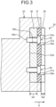
- FIG. 3 is an enlarged view of the roll chock liner illustrated in FIG. 2 .
- FIG. 1 is an exemplary and schematic diagram of a configuration of a tandem cold rolling mill 1 according to an embodiment.
- the tandem cold rolling mill 1 is one example of a rolling mill.
- a steel sheet 2 is used as an example of a material to be rolled that is rolled by the tandem cold rolling mill 1; however, the material to be rolled is not limited thereto, and the tandem cold rolling mill 1 may also be applied to an aluminum sheet, or a sheet made from any other metal, for example.
- the steel sheet 2, such as a magnetic steel sheet, a stainless steel sheet, and a high-carbon steel sheet, is of a steel type that is generally highly likely to vibrate.
- the tandem cold rolling mill 1 includes a plurality of stands 3 to 6 cold-rolling a steel sheet 2, for example.
- the plurality of stands 3 to 6 are arranged along a rolling direction X (conveying direction) of the steel sheet 2.
- the number of the stands 3 to 6 is not limited to four, and may also be one, two, three, or five or more.
- Each of the stands 3 to 6 includes a pair of work rolls 10, a pair of intermediate rolls 11, and a pair of backup rolls 12.
- the work rolls 10, the intermediate rolls 11, and the backup rolls 12 are arranged along an up-down direction intersecting the rolling direction X.
- Each of the stands 3 to 6 is what is called a 6-high mill stand having the intermediate roll 11 between the work roll 10 and the backup roll 12.
- tandem cold rolling mill 1 elements such as a tension roll, a deflector roll, a thickness meter, and a shape meter, not illustrated, are installed between adjacent two of the stands 3 to 6.
- the configuration of the tandem cold rolling mill 1 and the conveyor configured to convey the steel sheet 2 are not limited to any particular configuration or conveyor, and any known technologies may be used as appropriate.
- FIG. 2 is an exemplary and schematic diagram of the stand 3 included in the tandem cold rolling mill 1 according to the embodiment.
- the stand 3 also includes, for example, work roll chocks 20, work roll chock liners 30, intermediate roll chocks 21, intermediate roll chock liners 31, backup roll chocks 22, backup roll chock liners 32, and a mill housing 40.
- the work roll chocks 20 are provided to both ends of the pair of work rolls 10 in the axial direction (the direction perpendicular to the paper surface of FIG. 2 ). Each pair of the work roll chocks 20 rotatably supports the corresponding work roll 10, about the axis extending in the direction perpendicular to the paper surface of FIG. 2 . Recesses 20a each recessed toward the center in the rolling direction X (toward the work roll 10) are provided to both ends of each of the work roll chocks 20 in the rolling direction X. In each of the recesses 20a, a work roll chock liner 30, to be described later, is disposed.
- the work roll 10 is one example of the rolling mill roll
- the work roll chock 20 is one example of a roll chock
- the work roll chock liner 30 is one example of the roll chock liner.
- the intermediate roll chocks 21 are provided to both ends of the pair of intermediate rolls 11 in the axial direction (the direction perpendicular to the paper surface of FIG. 2 ). Each pair of the intermediate roll chocks 21 rotatably supports the corresponding intermediate roll 11 about the axis. Recesses 21a each recessed toward the center in the rolling direction X (toward the intermediate roll 11) are provided to both ends of each of the intermediate roll chocks 21 in the rolling direction X. In each of the recesses 21a, the intermediate roll chock liner 31 is disposed.
- the backup roll chocks 22 are provided to both ends of the pair of backup rolls 12 in the axial direction (the direction perpendicular to the paper surface of FIG. 2 ). Each pair of the backup roll chocks 22 rotatably supports the corresponding backup roll 12 about the axis. Recesses 22a each recessed toward the center in the rolling direction X (toward the backup roll 12) are provided to both ends of each of the backup roll chocks 22 in the rolling direction X. In each of the recesses 22a, the backup roll chock liner 32 is disposed.
- the mill housing 40 has a pair of side walls 40a, 40b that are disposed on both sides of the work roll chocks 20, the intermediate roll chocks 21, and the backup roll chocks 22, in the rolling direction X. A very small clearance is ensured between the pair of side walls 40a, 40b and each of the work roll chocks 20, the intermediate roll chocks 21, and the backup roll chocks 22 so as to make it easy to replace the roll chocks 20, 21, 22.
- the mill housing 40 also has a plurality of project blocks 41 projecting from the pair of side wall 40a, 40b toward the center in the rolling direction X (toward the work rolls 10, respectively).
- Each of the project blocks 41 has a project block liner or the like that comes into abutment against the work roll chock liner 30, absorbing the looseness (clearance) between the mill housing 40 and the work roll chock 20.
- the project blocks 41 may also be positioned between the mill housing 40 and the intermediate roll chock 21, and between the mill housing 40 and the backup roll chock 22, respectively, for example.
- FIG. 3 is an enlarged view of the work roll chock liner 30 illustrated in FIG. 2 .
- the work roll chock liner 30 includes a first liner plate 36, a second liner plate 38, and an elastic member 37, for example.
- the elastic member 37 and the second liner plate 38 are stacked on the first liner plate 36 in the rolling direction X.
- the first liner plate 36 has a rectangular plate-like shape extending along the bottom of the recess 20a on the work roll chock 20.
- the first liner plate 36 has openings 36a through which shafts 50b of fasteners 50 are passed, respectively, in the rolling direction X.
- the fasteners 50 are fixing members such as bolts or screws, and the work roll chock liner 30 and the work roll chock 20 are fixed therewith.
- the first liner plate 36 and the second liner plate 38 are made of a metal material, for example.
- the thickness W1 of the first liner plate 36 is set greater than the thickness W2 of the second liner plate 38 and the thickness of the elastic member 37. Specifically, the thickness W1 of the first liner plate 36 is set to approximately a half the thickness of the entire work roll chock liner 30, to ensure stiffness and strength for fastening the fasteners 50. In this embodiment, the thickness of the elastic member 37 is set to substantially the same as the thickness W2 of the second liner plate 38.
- the second liner plate 38 is positioned on the opposite side of the work roll chock 20 with respect to the first liner plate 36, in the rolling direction X.
- the second liner plate 38 has a rectangular plate-like shape extending along the first liner plate 36.
- the second liner plate 38 has openings 38a in which the heads 50a of the respective fasteners 50 are housed.
- Each of the openings 38a is a circular hole (relief cut) having a size slightly larger than the head 50a of the fastener 50, as an example.
- the elastic member 37 is a vibration-insulating rubber, for example, and is positioned between the first liner plate 36 and the second liner plate 38 in the rolling direction X.
- the elastic member 37 has a rectangular plate-like shape extending along the first liner plate 36, and is fixed to the first liner plate 36 and the second liner plate 38 by bonding, for example.
- the elastic member 37 can absorb the vibrations in the rolling direction X by elastically deforming between the first liner plate 36 and the second liner plate 38.
- the elastic member 37 has openings 37a in which the heads 50a of the respective fasteners 50 are housed.
- Each of the openings 37a is a circular hole (relief cut) having a size slightly larger than the head 50a of the fastener 50, as an example, and is in alignment with the corresponding opening 38a of the second liner plate 38 in the rolling direction X.
- the total thickness of the elastic member 37 and the second liner plate 38 is set greater than thickness of the head 50a of the fasteners 50.
- the thickness of the elastic member 37 and the thickness of the second liner plate 38 are set such that the heads 50a of the fasteners 50 do not stick out from the respective openings 37a, 38a in the rolling direction X.
- first liner plate 36, the second liner plate 38, and the elastic member 37 are provided to the work roll chock liner 30, but without limitation thereto, and the first liner plate 36, the second liner plate 38, and the elastic member 37 may also be provided to the intermediate roll chock liner 31 or the backup roll chock liner 32 illustrated in FIG. 2 .
- first liner plate 36, the second liner plate 38, and the elastic member 37 may be provided to at least one of the work roll chock liner 30, the intermediate roll chock liner 31, and the backup roll chock liner 32.
- the first liner plate 36, the second liner plate 38, and the elastic member 37 are provided to the work roll chock liner 30, for example, in each of the stands 4 to 6 other than the stand 3.
- Each of the other stands 4 to 6 has substantially the same configuration as that of the stand 3 described above.
- the number of the stands 3 to 6 provided with the first liner plate 36, the second liner plate 38, and the elastic member 37 is not limited to four, and may be one, two, or three, for example.
- the tandem cold rolling mill 1 includes a plurality of stands 3 to 6 configured to roll a steel sheet 2 (material to be rolled), and at least one stand 3, among the stands 3 to 6, includes: at least one pair of the work rolls 10 (rolling mill rolls); the work roll chocks 20 (roll chocks) rotatably supporting the work rolls 10; and the work roll chock liners 30 (roll chock liners) that each include the first liner plate 36 mounted on the work roll chock 20, the second liner plate 38 stacked on the first liner plate 36 in the rolling direction X, and the elastic member 37 interposed between the first liner plate 36 and the second liner plate 38.
- the stands 3 to 6 are each provided with the work roll chock liner 30 including the first liner plate 36, the second liner plate 38, and the elastic member 37.
- the elastic members 37 provided to the work roll chock liners 30 in the respective stands 3 to 6 can suppress the vibrations during the rolling process, and therefore, it becomes possible to suppress a cyclic change in the thickness of the steel sheet 2 due to the vibrations during the rolling process, more reliably.
- the first liner plate 36 is fastened to the work roll chock 20 using a fastener 50 passed through the first liner plate 36 in the rolling direction X, and the second liner plate 38 and the elastic member 37 have openings 38a, 37a, respectively, in which the head 50a of the fastener 50 is housed.
- One embodiment of the present invention has been described above as an example; however, the embodiment is merely one example, and is not intended to limit the scope of the present invention in any way.
- the embodiment may be implemented in other configurations, and various omissions, replacements, combinations, and modifications are still possible within the scope not deviating from the gist of the present invention.
- the embodiment may be implemented with appropriate changes in the configurations and specifications, such as the shapes (e.g., structures, types, directions, forms, sizes, length, width, thickness, height, numbers, arrangement, positions, and materials).
- a rolling mill a cold rolling method, and a steel sheet manufacturing method capable of suppressing vibrations during a rolling process while suppressing wearing of a liner of the roll chock.
Landscapes
- Engineering & Computer Science (AREA)
- Mechanical Engineering (AREA)
- Metal Rolling (AREA)
- Reduction Rolling/Reduction Stand/Operation Of Reduction Machine (AREA)
Abstract
Description
- The present invention relates to a rolling mill, a cold rolling method, and a steel sheet manufacturing method.
- In production lines such as those for cold-rolled steel sheets, sometimes vibrations occur during a cold-rolling process, due to various factors. Such vibrations could cause a cyclic change in the thickness of a steel sheet that is a material to be rolled, and therefore, when such vibrations occur, it is important to suppress vibrations so as to prevent the vibrations from affecting the material to be rolled.
- As an example,
Patent Literature 1 discloses a cold-rolling facility and a cold rolling method capable of suppressing chattering (vibrations) in the horizontal direction, with the use of rolling oil supplied to a stand in the rolling mill. - Patent Literature 1:
Japanese Patent No. 7020530 - For this type of rolling mill, there has been some disclosures pertinent to, as a method for suppressing vibrations during a rolling process, a method for mounting an elastic member such as a vibration-insulating rubber on the roll chock liner included in a stand, in addition to the conventional method of suppressing vibration using roll oil, as described above.
- However, in a structure in which such an elastic member is stacked and mounted on the roll chock liner in the rolling direction, an exposed surface of the elastic member, facing the opposite side of the roll chock, wears out, and thus it could be difficult to put such an elastic member into industrial use.
- The present invention is made in consideration of the challenges described above, and an object of the present invention is to provide a rolling mill, a cold rolling method, and a steel sheet manufacturing method capable of suppressing vibration during a rolling process while suppressing wearing of a roll chock liner.
- To solve the problem and achieve the object, a rolling mill according to the present invention includes a plurality of stands configured to roll a material to be rolled, wherein at least one stand, among the stands, includes: at least one pair of rolling mill rolls; a roll chock that rotatably support the rolling mill rolls; and a roll chock liner that includes a first liner plate mounted on the roll chock, a second liner plate stacked on the first liner plate in a rolling direction, and an elastic member interposed between the first liner plate and the second liner plate.
- Moreover, each stands may be provided with the roll chock liner including the first liner plate, the second liner plate, and the elastic member.
- Moreover, the first liner plate may be fastened to the roll chock with a fastener passed through the first liner plate in the rolling direction, and each of the second liner plate and the elastic member may have an opening in which a head of the fastener is housed.
- Moreover, a cold rolling method according to the present invention includes a step of cold-rolling a material to be rolled using the rolling mill according to the present invention.
- Moreover, a steel sheet manufacturing method according to the present invention includes a step of manufacturing a steel sheet as a material to be rolled, using the cold rolling method according to the present invention.
- According to the present invention, by interposing an elastic member between a first liner plate and a second liner plate that are stacked in the rolling direction, it is possible to suppress the elastic member from becoming exposed and wearing out on a side facing the opposite side of the roll chock. With such a configuration, it is possible to provide a rolling mill, a cold rolling method, and a steel sheet manufacturing method capable of suppressing vibration during a rolling process while suppressing wearing of the roll chock liner.
-
FIG. 1 is an exemplary and schematic diagram of a rolling mill according to an embodiment.FIG. 2 is an exemplary and schematic sectional view of a stand included in the rolling mill according to the embodiment.FIG. 3 is an enlarged view of the roll chock liner illustrated inFIG. 2 . - An exemplary embodiment of the present invention is disclosed below. Configurations according to the embodiment and actions and advantageous effects achieved thereby are described below only for illustrative purposes. The present invention may also be implemented in configurations other than those described below in the embodiment. Furthermore, according to the present invention, at least one of various advantageous effects (including secondary effects) achieved by the configurations can be achieved.
- In the description herein, ordinal numbers given to parts, members, portions, positions, directions, and the like are only for the purpose of distinguishing such parts, members, portions, positions, directions, and the like from one another, and are not intended to indicate any order or priorities.
-
FIG. 1 is an exemplary and schematic diagram of a configuration of a tandem cold rollingmill 1 according to an embodiment. The tandem cold rollingmill 1 is one example of a rolling mill. In the description hereunder, asteel sheet 2 is used as an example of a material to be rolled that is rolled by the tandem cold rollingmill 1; however, the material to be rolled is not limited thereto, and the tandem cold rollingmill 1 may also be applied to an aluminum sheet, or a sheet made from any other metal, for example. Thesteel sheet 2, such as a magnetic steel sheet, a stainless steel sheet, and a high-carbon steel sheet, is of a steel type that is generally highly likely to vibrate. - As illustrated in
FIG. 1 , the tandem cold rollingmill 1 includes a plurality ofstands 3 to 6 cold-rolling asteel sheet 2, for example. The plurality ofstands 3 to 6 are arranged along a rolling direction X (conveying direction) of thesteel sheet 2. The number of thestands 3 to 6 is not limited to four, and may also be one, two, three, or five or more. - Each of the
stands 3 to 6 includes a pair ofwork rolls 10, a pair ofintermediate rolls 11, and a pair ofbackup rolls 12. The work rolls 10, theintermediate rolls 11, and thebackup rolls 12 are arranged along an up-down direction intersecting the rolling direction X. Each of thestands 3 to 6 is what is called a 6-high mill stand having theintermediate roll 11 between thework roll 10 and thebackup roll 12. - In the tandem cold rolling
mill 1, elements such as a tension roll, a deflector roll, a thickness meter, and a shape meter, not illustrated, are installed between adjacent two of thestands 3 to 6. The configuration of the tandem cold rollingmill 1 and the conveyor configured to convey thesteel sheet 2 are not limited to any particular configuration or conveyor, and any known technologies may be used as appropriate. -
FIG. 2 is an exemplary and schematic diagram of thestand 3 included in the tandem cold rollingmill 1 according to the embodiment. As illustrated inFIG. 2 , thestand 3 also includes, for example,work roll chocks 20, workroll chock liners 30,intermediate roll chocks 21, intermediateroll chock liners 31,backup roll chocks 22, backuproll chock liners 32, and amill housing 40. - The
work roll chocks 20 are provided to both ends of the pair ofwork rolls 10 in the axial direction (the direction perpendicular to the paper surface ofFIG. 2 ). Each pair of the work roll chocks 20 rotatably supports thecorresponding work roll 10, about the axis extending in the direction perpendicular to the paper surface ofFIG. 2 . Recesses 20a each recessed toward the center in the rolling direction X (toward the work roll 10) are provided to both ends of each of thework roll chocks 20 in the rolling direction X. In each of therecesses 20a, a workroll chock liner 30, to be described later, is disposed. In this embodiment, thework roll 10 is one example of the rolling mill roll; thework roll chock 20 is one example of a roll chock; and the workroll chock liner 30 is one example of the roll chock liner. - The
intermediate roll chocks 21 are provided to both ends of the pair ofintermediate rolls 11 in the axial direction (the direction perpendicular to the paper surface ofFIG. 2 ). Each pair of the intermediate roll chocks 21 rotatably supports the correspondingintermediate roll 11 about the axis.Recesses 21a each recessed toward the center in the rolling direction X (toward the intermediate roll 11) are provided to both ends of each of theintermediate roll chocks 21 in the rolling direction X. In each of therecesses 21a, the intermediateroll chock liner 31 is disposed. - The
backup roll chocks 22 are provided to both ends of the pair ofbackup rolls 12 in the axial direction (the direction perpendicular to the paper surface ofFIG. 2 ). Each pair of the backup roll chocks 22 rotatably supports thecorresponding backup roll 12 about the axis. Recesses 22a each recessed toward the center in the rolling direction X (toward the backup roll 12) are provided to both ends of each of thebackup roll chocks 22 in the rolling direction X. In each of therecesses 22a, the backuproll chock liner 32 is disposed. - The
mill housing 40 has a pair ofside walls work roll chocks 20, theintermediate roll chocks 21, and thebackup roll chocks 22, in the rolling direction X. A very small clearance is ensured between the pair ofside walls work roll chocks 20, the intermediate roll chocks 21, and thebackup roll chocks 22 so as to make it easy to replace theroll chocks - The
mill housing 40 also has a plurality ofproject blocks 41 projecting from the pair ofside wall work rolls 10, respectively). Each of theproject blocks 41 has a project block liner or the like that comes into abutment against the workroll chock liner 30, absorbing the looseness (clearance) between themill housing 40 and thework roll chock 20. - The
project blocks 41 may also be positioned between themill housing 40 and theintermediate roll chock 21, and between the mill housing 40 and thebackup roll chock 22, respectively, for example. -
FIG. 3 is an enlarged view of the workroll chock liner 30 illustrated inFIG. 2 . As illustrated inFIG. 3 , the work roll chockliner 30 includes afirst liner plate 36, asecond liner plate 38, and anelastic member 37, for example. Theelastic member 37 and thesecond liner plate 38 are stacked on thefirst liner plate 36 in the rolling direction X. - The
first liner plate 36 has a rectangular plate-like shape extending along the bottom of therecess 20a on thework roll chock 20. Thefirst liner plate 36 hasopenings 36a through whichshafts 50b offasteners 50 are passed, respectively, in the rolling direction X. Thefasteners 50 are fixing members such as bolts or screws, and the work roll chockliner 30 and the work roll chock 20 are fixed therewith. Thefirst liner plate 36 and thesecond liner plate 38 are made of a metal material, for example. - In this embodiment, the thickness W1 of the
first liner plate 36 is set greater than the thickness W2 of thesecond liner plate 38 and the thickness of theelastic member 37. Specifically, the thickness W1 of thefirst liner plate 36 is set to approximately a half the thickness of the entire work roll chockliner 30, to ensure stiffness and strength for fastening thefasteners 50. In this embodiment, the thickness of theelastic member 37 is set to substantially the same as the thickness W2 of thesecond liner plate 38. - The
second liner plate 38 is positioned on the opposite side of the work roll chock 20 with respect to thefirst liner plate 36, in the rolling direction X. Thesecond liner plate 38 has a rectangular plate-like shape extending along thefirst liner plate 36. Thesecond liner plate 38 hasopenings 38a in which theheads 50a of therespective fasteners 50 are housed. Each of theopenings 38a is a circular hole (relief cut) having a size slightly larger than thehead 50a of thefastener 50, as an example. - The
elastic member 37 is a vibration-insulating rubber, for example, and is positioned between thefirst liner plate 36 and thesecond liner plate 38 in the rolling direction X. Theelastic member 37 has a rectangular plate-like shape extending along thefirst liner plate 36, and is fixed to thefirst liner plate 36 and thesecond liner plate 38 by bonding, for example. Theelastic member 37 can absorb the vibrations in the rolling direction X by elastically deforming between thefirst liner plate 36 and thesecond liner plate 38. - The
elastic member 37 hasopenings 37a in which theheads 50a of therespective fasteners 50 are housed. Each of theopenings 37a is a circular hole (relief cut) having a size slightly larger than thehead 50a of thefastener 50, as an example, and is in alignment with thecorresponding opening 38a of thesecond liner plate 38 in the rolling direction X. In this embodiment, by fastening thefastener 50 only to thefirst liner plate 36, instead of the entire work roll chockliner 30, loosening of the fastenedfastener 50 is suppressed by the elasticity of theelastic member 37. - In this embodiment, the total thickness of the
elastic member 37 and thesecond liner plate 38 is set greater than thickness of thehead 50a of thefasteners 50. In other words, the thickness of theelastic member 37 and the thickness of thesecond liner plate 38 are set such that theheads 50a of thefasteners 50 do not stick out from therespective openings - Furthermore, described in the embodiment is an example in which the
first liner plate 36, thesecond liner plate 38, and theelastic member 37 are provided to the work roll chockliner 30, but without limitation thereto, and thefirst liner plate 36, thesecond liner plate 38, and theelastic member 37 may also be provided to the intermediate roll chockliner 31 or the backup roll chockliner 32 illustrated inFIG. 2 . In other words, thefirst liner plate 36, thesecond liner plate 38, and theelastic member 37 may be provided to at least one of the work roll chockliner 30, the intermediate roll chockliner 31, and the backup roll chockliner 32. - Furthermore, in this embodiment, the
first liner plate 36, thesecond liner plate 38, and theelastic member 37 are provided to the work roll chockliner 30, for example, in each of the stands 4 to 6 other than thestand 3. Each of the other stands 4 to 6 has substantially the same configuration as that of thestand 3 described above. The number of thestands 3 to 6 provided with thefirst liner plate 36, thesecond liner plate 38, and theelastic member 37 is not limited to four, and may be one, two, or three, for example. - As described above, in this embodiment, the tandem cold rolling mill 1 (rolling mill) includes a plurality of
stands 3 to 6 configured to roll a steel sheet 2 (material to be rolled), and at least onestand 3, among thestands 3 to 6, includes: at least one pair of the work rolls 10 (rolling mill rolls); the work roll chocks 20 (roll chocks) rotatably supporting the work rolls 10; and the work roll chock liners 30 (roll chock liners) that each include thefirst liner plate 36 mounted on thework roll chock 20, thesecond liner plate 38 stacked on thefirst liner plate 36 in the rolling direction X, and theelastic member 37 interposed between thefirst liner plate 36 and thesecond liner plate 38. - With such a configuration, for example, by disposing the
elastic member 37 in a manner interposed between thefirst liner plate 36 and thesecond liner plate 38 that are stacked in the rolling direction X, it is possible to suppress a side of theelastic member 37 from becoming exposed and wearing out on a side facing the opposite side of the work roll chock 20 (on the side facing theproject block 41 on the mill housing 40). With this, it is possible to provide the tandemcold rolling mill 1, the cold rolling method, and the manufacturing method of thesteel sheet 2 capable of suppressing vibration during the rolling process, while suppressing wearing of the work roll chockliner 30. - Furthermore, in this embodiment, the
stands 3 to 6 are each provided with the work roll chockliner 30 including thefirst liner plate 36, thesecond liner plate 38, and theelastic member 37. - With such a configuration, for example, the
elastic members 37 provided to the workroll chock liners 30 in therespective stands 3 to 6 can suppress the vibrations during the rolling process, and therefore, it becomes possible to suppress a cyclic change in the thickness of thesteel sheet 2 due to the vibrations during the rolling process, more reliably. - Furthermore, in this embodiment, the
first liner plate 36 is fastened to the work roll chock 20 using afastener 50 passed through thefirst liner plate 36 in the rolling direction X, and thesecond liner plate 38 and theelastic member 37 haveopenings head 50a of thefastener 50 is housed. - With such a configuration, for example, it is possible to fasten only the
first liner plate 36, but not the entire work roll chockliner 30, and therefore, loosening of the fastenedfastener 50 can be suppressed by the elasticity of theelastic member 37. - One embodiment of the present invention has been described above as an example; however, the embodiment is merely one example, and is not intended to limit the scope of the present invention in any way. The embodiment may be implemented in other configurations, and various omissions, replacements, combinations, and modifications are still possible within the scope not deviating from the gist of the present invention. Furthermore, the embodiment may be implemented with appropriate changes in the configurations and specifications, such as the shapes (e.g., structures, types, directions, forms, sizes, length, width, thickness, height, numbers, arrangement, positions, and materials).
- According to the present invention, it is possible to provide a rolling mill, a cold rolling method, and a steel sheet manufacturing method capable of suppressing vibrations during a rolling process while suppressing wearing of a liner of the roll chock.
-
- 1
- tandem cold rolling mill (rolling mill)
- 2
- steel sheet (material to be rolled)
- 3 to 6
- stand
- 10
- work roll (rolling mill roll)
- 20
- work roll chock (roll chock)
- 30
- work roll chock liner (roll chock liner)
- 36
- first liner plate
- 37
- elastic member
- 38
- second liner plate
- 50
- fastener
- 50a
- head
- X
- rolling direction
Claims (6)
- A rolling mill comprising a plurality of stands configured to roll a material to be rolled, wherein
at least one stand, among the stands, includes:at least one pair of rolling mill rolls;a roll chock that rotatably support the rolling mill rolls; anda roll chock liner that includes a first liner plate mounted on the roll chock, a second liner plate stacked on the first liner plate in a rolling direction, and an elastic member interposed between the first liner plate and the second liner plate. - The rolling mill according to claim 1, wherein the stands are each provided with the roll chock liner including the first liner plate, the second liner plate, and the elastic member.
- The rolling mill according to claim 1, whereinthe first liner plate is fastened to the roll chock with a fastener passed through the first liner plate in the rolling direction, andeach of the second liner plate and the elastic member has an opening in which a head of the fastener is housed.
- The rolling mill according to claim 2, whereinthe first liner plate is fastened to the roll chock with a fastener passed through the first liner plate in the rolling direction, andeach of the second liner plate and the elastic member has an opening in which a head of the fastener is housed.
- A cold rolling method comprising a step of cold-rolling a material to be rolled using the rolling mill according to claim 1.
- A steel sheet manufacturing method comprising a step of manufacturing a steel sheet as a material to be rolled, using the cold rolling method according to claim 5.
Applications Claiming Priority (2)
| Application Number | Priority Date | Filing Date | Title |
|---|---|---|---|
| JP2022085431A JP7666404B2 (en) | 2022-05-25 | 2022-05-25 | Rolling mill, cold rolling method, and method for manufacturing steel sheet |
| PCT/JP2022/048282 WO2023228460A1 (en) | 2022-05-25 | 2022-12-27 | Rolling mill, cold rolling method, and method for producing steel sheet |
Publications (3)
| Publication Number | Publication Date |
|---|---|
| EP4487973A1 true EP4487973A1 (en) | 2025-01-08 |
| EP4487973A4 EP4487973A4 (en) | 2025-06-25 |
| EP4487973B1 EP4487973B1 (en) | 2026-04-01 |
Family
ID=88918870
Family Applications (1)
| Application Number | Title | Priority Date | Filing Date |
|---|---|---|---|
| EP22943859.3A Active EP4487973B1 (en) | 2022-05-25 | 2022-12-27 | Rolling mill, cold rolling method, and method for producing steel sheet |
Country Status (8)
| Country | Link |
|---|---|
| US (1) | US20250229311A1 (en) |
| EP (1) | EP4487973B1 (en) |
| JP (1) | JP7666404B2 (en) |
| KR (1) | KR20250117766A (en) |
| CN (1) | CN119212805A (en) |
| MX (1) | MX2024014479A (en) |
| TW (1) | TWI839065B (en) |
| WO (1) | WO2023228460A1 (en) |
Family Cites Families (10)
| Publication number | Priority date | Publication date | Assignee | Title |
|---|---|---|---|---|
| JPS5828643Y2 (en) * | 1977-04-18 | 1983-06-22 | 新日本製鐵株式会社 | hot rolling mill |
| JPS6041283Y2 (en) * | 1980-12-23 | 1985-12-16 | 石川島播磨重工業株式会社 | rolling equipment |
| JPS5944582U (en) * | 1982-09-14 | 1984-03-24 | 三ツ星ベルト株式会社 | Rubber liner mounting structure |
| DE3717316A1 (en) * | 1987-05-22 | 1988-12-15 | Achenbach Buschhuetten Gmbh | MONITORING DEVICE FOR ROLLER BEARINGS IN ROLLING MILLS |
| JPH0810807A (en) * | 1994-06-27 | 1996-01-16 | Kobe Steel Ltd | Rolling mill |
| EP1008509B1 (en) * | 1997-09-05 | 2005-11-23 | Komatsu Ltd | Elastic flat tread |
| JP4820062B2 (en) | 2003-04-02 | 2011-11-24 | Jfeスチール株式会社 | Cross roll rolling mill and rolling method using the same |
| TWI247633B (en) * | 2003-04-02 | 2006-01-21 | Jfe Steel Corp | Cross-rolling rolling machine and method of using same |
| JP5564857B2 (en) * | 2009-08-31 | 2014-08-06 | Jfeスチール株式会社 | Damping strengthening rolling mill |
| JP7020530B1 (en) * | 2020-10-29 | 2022-02-16 | Jfeスチール株式会社 | Cold rolling equipment, cold rolling method, and metal plate manufacturing method |
-
2022
- 2022-05-25 JP JP2022085431A patent/JP7666404B2/en active Active
- 2022-12-27 KR KR1020247036071A patent/KR20250117766A/en active Pending
- 2022-12-27 CN CN202280096104.XA patent/CN119212805A/en active Pending
- 2022-12-27 WO PCT/JP2022/048282 patent/WO2023228460A1/en not_active Ceased
- 2022-12-27 EP EP22943859.3A patent/EP4487973B1/en active Active
- 2022-12-27 US US18/853,478 patent/US20250229311A1/en active Pending
-
2023
- 2023-01-09 TW TW112100777A patent/TWI839065B/en active
-
2024
- 2024-11-22 MX MX2024014479A patent/MX2024014479A/en unknown
Also Published As
| Publication number | Publication date |
|---|---|
| KR20250117766A (en) | 2025-08-05 |
| EP4487973B1 (en) | 2026-04-01 |
| MX2024014479A (en) | 2025-01-09 |
| JP2023173279A (en) | 2023-12-07 |
| EP4487973A4 (en) | 2025-06-25 |
| US20250229311A1 (en) | 2025-07-17 |
| WO2023228460A1 (en) | 2023-11-30 |
| TW202345991A (en) | 2023-12-01 |
| CN119212805A (en) | 2024-12-27 |
| TWI839065B (en) | 2024-04-11 |
| JP7666404B2 (en) | 2025-04-22 |
Similar Documents
| Publication | Publication Date | Title |
|---|---|---|
| US5644942A (en) | Roll stand raft assembly | |
| EP2248609B1 (en) | Plate rolling mill and plate rolling method | |
| EP1230991B1 (en) | Tandem rolling mill facility and rolling method using the same | |
| EP4487973B1 (en) | Rolling mill, cold rolling method, and method for producing steel sheet | |
| US20250178670A1 (en) | Vehicle chassis crossmember apparatuses and methods thereof | |
| US20110113847A1 (en) | Cluster-type multistage rolling mill | |
| EP2556903A1 (en) | Operation control method of tandem rolling mill, and method for producing hot-rolled steel sheet using same | |
| US8302446B2 (en) | Roll stand | |
| JP2000176504A (en) | Hot rolled steel strip skin pass mill | |
| JP2008200727A (en) | Device for drawing-out cast ingot | |
| CN223557088U (en) | Material area fixed knot constructs and punch press | |
| US20080295727A1 (en) | Railcar Support Beam System and Method | |
| RU2699489C1 (en) | Rolling stand "quarto" | |
| JP2014024102A (en) | Conditioning rolling method of cold rolled steel sheet | |
| KR101744286B1 (en) | Apparatus of tension reel segment gripper for winding a coil | |
| JPS61226105A (en) | Roll for multi-stages rolling mill | |
| EP0400145A1 (en) | Roll stand of rolling mill | |
| JP5581773B2 (en) | Method for preventing breakage of metal strip in cold rolling mill | |
| JPH0110088Y2 (en) | ||
| RU2198755C2 (en) | Roll fitting of rolling mill | |
| KR102425952B1 (en) | Metal strip material, slitting method, and measuring method for strip material meandering | |
| JPS63295019A (en) | Double row forming roll | |
| JPH07185616A (en) | Installation device for rolling mill | |
| JPH09239413A (en) | Rolling machine, rolling equipment and rolling method | |
| SU1214270A1 (en) | Method of adjusting mill for forming corrugated sections |
Legal Events
| Date | Code | Title | Description |
|---|---|---|---|
| STAA | Information on the status of an ep patent application or granted ep patent |
Free format text: STATUS: THE INTERNATIONAL PUBLICATION HAS BEEN MADE |
|
| PUAI | Public reference made under article 153(3) epc to a published international application that has entered the european phase |
Free format text: ORIGINAL CODE: 0009012 |
|
| STAA | Information on the status of an ep patent application or granted ep patent |
Free format text: STATUS: REQUEST FOR EXAMINATION WAS MADE |
|
| 17P | Request for examination filed |
Effective date: 20240930 |
|
| AK | Designated contracting states |
Kind code of ref document: A1 Designated state(s): AL AT BE BG CH CY CZ DE DK EE ES FI FR GB GR HR HU IE IS IT LI LT LU LV MC ME MK MT NL NO PL PT RO RS SE SI SK SM TR |
|
| A4 | Supplementary search report drawn up and despatched |
Effective date: 20250526 |
|
| RIC1 | Information provided on ipc code assigned before grant |
Ipc: B21B 38/00 20060101ALI20250521BHEP Ipc: B21B 1/22 20060101ALI20250521BHEP Ipc: B21B 31/02 20060101AFI20250521BHEP |
|
| DAV | Request for validation of the european patent (deleted) | ||
| DAX | Request for extension of the european patent (deleted) | ||
| GRAP | Despatch of communication of intention to grant a patent |
Free format text: ORIGINAL CODE: EPIDOSNIGR1 |
|
| STAA | Information on the status of an ep patent application or granted ep patent |
Free format text: STATUS: GRANT OF PATENT IS INTENDED |
|
| INTG | Intention to grant announced |
Effective date: 20260105 |
|
| GRAS | Grant fee paid |
Free format text: ORIGINAL CODE: EPIDOSNIGR3 |
|
| GRAA | (expected) grant |
Free format text: ORIGINAL CODE: 0009210 |
|
| STAA | Information on the status of an ep patent application or granted ep patent |
Free format text: STATUS: THE PATENT HAS BEEN GRANTED |
|
| AK | Designated contracting states |
Kind code of ref document: B1 Designated state(s): AL AT BE BG CH CY CZ DE DK EE ES FI FR GB GR HR HU IE IS IT LI LT LU LV MC ME MK MT NL NO PL PT RO RS SE SI SK SM TR |
|
| REG | Reference to a national code |
Ref country code: CH Ref legal event code: F10 Free format text: ST27 STATUS EVENT CODE: U-0-0-F10-F00 (AS PROVIDED BY THE NATIONAL OFFICE) Effective date: 20260401 Ref country code: GB Ref legal event code: FG4D |
|
| REG | Reference to a national code |
Ref country code: DE Ref legal event code: R096 Ref document number: 602022033807 Country of ref document: DE |
|
| REG | Reference to a national code |
Ref country code: IE Ref legal event code: FG4D |