EP4487960A1 - Rotary material reduction tool - Google Patents
Rotary material reduction tool Download PDFInfo
- Publication number
- EP4487960A1 EP4487960A1 EP24185418.1A EP24185418A EP4487960A1 EP 4487960 A1 EP4487960 A1 EP 4487960A1 EP 24185418 A EP24185418 A EP 24185418A EP 4487960 A1 EP4487960 A1 EP 4487960A1
- Authority
- EP
- European Patent Office
- Prior art keywords
- collar
- drum
- opening
- hammer
- flange
- Prior art date
- Legal status (The legal status is an assumption and is not a legal conclusion. Google has not performed a legal analysis and makes no representation as to the accuracy of the status listed.)
- Pending
Links
Images










Classifications
-
- B—PERFORMING OPERATIONS; TRANSPORTING
- B02—CRUSHING, PULVERISING, OR DISINTEGRATING; PREPARATORY TREATMENT OF GRAIN FOR MILLING
- B02C—CRUSHING, PULVERISING, OR DISINTEGRATING IN GENERAL; MILLING GRAIN
- B02C13/00—Disintegrating by mills having rotary beater elements ; Hammer mills
- B02C13/26—Details
- B02C13/28—Shape or construction of beater elements
- B02C13/2804—Shape or construction of beater elements the beater elements being rigidly connected to the rotor
-
- B—PERFORMING OPERATIONS; TRANSPORTING
- B23—MACHINE TOOLS; METAL-WORKING NOT OTHERWISE PROVIDED FOR
- B23P—METAL-WORKING NOT OTHERWISE PROVIDED FOR; COMBINED OPERATIONS; UNIVERSAL MACHINE TOOLS
- B23P23/00—Machines or arrangements of machines for performing specified combinations of different metal-working operations not covered by a single other subclass
-
- B—PERFORMING OPERATIONS; TRANSPORTING
- B02—CRUSHING, PULVERISING, OR DISINTEGRATING; PREPARATORY TREATMENT OF GRAIN FOR MILLING
- B02C—CRUSHING, PULVERISING, OR DISINTEGRATING IN GENERAL; MILLING GRAIN
- B02C13/00—Disintegrating by mills having rotary beater elements ; Hammer mills
- B02C13/02—Disintegrating by mills having rotary beater elements ; Hammer mills with horizontal rotor shaft
- B02C13/06—Disintegrating by mills having rotary beater elements ; Hammer mills with horizontal rotor shaft with beaters rigidly connected to the rotor
-
- B—PERFORMING OPERATIONS; TRANSPORTING
- B02—CRUSHING, PULVERISING, OR DISINTEGRATING; PREPARATORY TREATMENT OF GRAIN FOR MILLING
- B02C—CRUSHING, PULVERISING, OR DISINTEGRATING IN GENERAL; MILLING GRAIN
- B02C18/00—Disintegrating by knives or other cutting or tearing members which chop material into fragments
- B02C18/06—Disintegrating by knives or other cutting or tearing members which chop material into fragments with rotating knives
- B02C18/16—Details
- B02C18/18—Knives; Mountings thereof
-
- B—PERFORMING OPERATIONS; TRANSPORTING
- B02—CRUSHING, PULVERISING, OR DISINTEGRATING; PREPARATORY TREATMENT OF GRAIN FOR MILLING
- B02C—CRUSHING, PULVERISING, OR DISINTEGRATING IN GENERAL; MILLING GRAIN
- B02C21/00—Disintegrating plant with or without drying of the material
- B02C21/02—Transportable disintegrating plant
-
- B—PERFORMING OPERATIONS; TRANSPORTING
- B02—CRUSHING, PULVERISING, OR DISINTEGRATING; PREPARATORY TREATMENT OF GRAIN FOR MILLING
- B02C—CRUSHING, PULVERISING, OR DISINTEGRATING IN GENERAL; MILLING GRAIN
- B02C2210/00—Codes relating to different types of disintegrating devices
- B02C2210/02—Features for generally used wear parts on beaters, knives, rollers, anvils, linings and the like
Definitions
- This present disclosure relates to material reducing machines such as grinders, shredders, and chippers.
- Material reducing machines are used to reduce the size of material such as waste material.
- Example waste materials include waste wood (e.g., trees, brush, stumps, pallets, railroad ties, etc.), peat moss, paper, wet organic materials, industrial waste, garbage, construction waste, and the like.
- a typical material reducing machine such as a grinder, a chipper, or a shredder includes a rotor to which a plurality of reducers (e.g., teeth, cutters, blades, grinding tips, chisels, etc.) are mounted.
- the reducers are typically mounted about the circumference of the rotor and are carried with the rotor about an axis of rotation of the rotor as the rotor is rotated.
- the rotor is rotated, and waste material is fed adjacent to the rotor such that contact between the reducers and the waste material provides a reducing or comminuting action with respect to the waste material.
- Grinders and chippers typically are configured to reduce material through direct impact of the reducers against the material.
- shredders are commonly configured such that the reducers operate in cooperation with a comb structure which intermeshes with the reducers as the rotor rotates.
- material fed into the shredder is forced through the comb structure by the reducers as the rotor rotates thereby providing a shredding action.
- the rotors of grinders and chippers typically operate at higher rotational speeds than the rotors of shredders.
- the reducing rotors of material reducing machines are subjected to extreme loads. Although the loading differs, due to the differing speeds, the reducing rotor must be robustly designed to withstand the loads. Further, the reducing rotor and its attached components, such as hammers and cutters, can experience high rates of wear, particularly if the waste material is abrasive. For this reason, attached components are typically replaceable.
- a method of assembling a rotary material reduction tool includes providing a drum having an outer surface extending about a rotational axis of the drum.
- a collar is assembled into a first opening from an outside of the drum into the outer surface of the drum until a portion of the collar extends into the drum and a flange of the collar extends beyond the first opening and along the outer surface of the drum.
- the flange of the collar and the outer surface of the drum are welded together.
- a hammer is inserted through the collar such that a portion therefore remains exposed. The hammer is secured to the collar.
- a rotary material reduction tool has a drum, a collar, and a hammer.
- the drum has an outer surface that extends about a rotational axis of the drum.
- the drum has a first opening defined in the outer surface of the drum.
- the collar is received in the first opening.
- a first portion of the collar extends into the drum, and a flange of the collar extends beyond the first opening and along the outer surface of the drum.
- the hammer extends through the collar and into the drum.
- the hammer has an exposed portion. The flange of the collar and the outer surface of the drum are welded together.
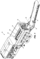
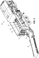
- FIGS. 1-3 depict a material reducing machine 20 that is one example of a type of material reducing machine in which a reducing rotor in accordance with the principles of the present disclosure can be incorporated.
- the rotary material reducing machine 20 is depicted as a shredder, but it will be appreciated that aspects of the present disclosure are also applicable to other types of material reducing machines such as grinders and chippers.
- the rotary material reducing machine 20 can be a relatively slow-speed shredder at which the rotor (described below in detail) is operated at speeds less than or equal to 40 rotations per minute during shredding operations.
- the rotary material reducing machine 20 can be a relatively fast-speed grinder or chipper at which the rotor is operated at speeds more than 40 rotations per minute during shredding operations.
- the rotary material reducing machine 20 includes a main framework defining a reducing box 22 in which a reducing rotor 24 is positioned.
- the reducing rotor 24 is mounted to rotate within the reducing box 22 about a central axis 26.
- the reducing rotor 24 may be rotationally mounted to the reducing box 22 via bearings.
- a plurality of reducers 28 are mounted at an exterior of the reducing rotor 24. When the reducing rotor 24 is rotated about the central axis 26, the reducers 28 are carried by the reducing rotor 24 along circular reducing paths that surround the central axis 26.
- the rotary material reducing machine 20 includes a hopper 30 above the reducing rotor 24 for allowing the to-be-reduced material to be fed into the reducing box 22.
- the hopper 30 optionally includes a screen (not shown) that mounts below the reducing rotor 24 for controlling the size of the reduced product which is output from the reducing box 22.
- the rotary material reducing machine 20 may further include a shredding comb 32 mounted within the reducing box 22.
- the shredding comb 32 includes a plurality of comb teeth, and the shredding comb 32 is positioned relative to the reducing rotor 24 such that the reducers 28 of the reducing rotor 24 intermesh with the comb teeth of the shredding comb 32 as the reducing rotor 24 is rotated about the central axis 26. In other words, as the reducing rotor 24 rotates, the reducers 28 pass between corresponding comb teeth of the shredding comb 32.
- the rotary material reducing machine 20 also includes a powertrain (not shown) for driving the rotation of the reducing rotor 24 about the central axis 26.
- the powertrain can include a prime mover (e.g., an engine) that provides the power required to drive rotation of the reducing rotor 24.
- the powertrain can also include a transmission for transferring the power from the prime mover to the reducing rotor 24.
- the power can be transferred in the form of torque.
- the rotary material reducing machine 20 may also include one or more conveyors 34 for transferring the reduced product discharged from the reducing box 22 away from the reducing box 22.
- material desired to be reduced is fed into the reducing box 22 through the hopper 30.
- the reducing rotor 24 is rotated about the central axis 26 by the powertrain.
- the material fed into the reducing box 22 is impacted by the reducers 28 of the reducing rotor 24, and the material is forced by the reducers 28 through the shredding comb 32 thereby causing the material to be reduced in size via shredding.
- the shredded material forced through the shredding comb 32 can be deposited on the conveyor 34 and transferred by the conveyor 34 to a collection location such as a truck bed or a pile on the ground.
- the hopper 30 includes a sizing screen below the reducing rotor 24, material that has been reduced to a size small enough to pass through the screen is deposited on the conveyor 34 while the remainder of the material is recirculated by the reducing rotor 24 back into the reducing box 22 for further processing until it is small enough to pass through the screen.
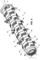
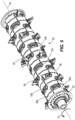
- FIGS. 4-8 illustrate a reducing rotor system 50 having a drum 52 (e.g., a reducing rotor shown separately in FIG. 9 ) that can be integrated into a material reducing machine such as the rotary material reducing machine 20.
- the reducing rotor system 50 is configured as a rotary material reduction tool.
- the reducing rotor system 50 is rotatable about a central rotational axis 54.
- the reducing rotor system 50 is mountable in a material reducing machine (e.g., in the reducing box 22 of the rotary material reducing machine 20), and when mounted in the rotary material reducing machine 20, the rotational axis 54 of the reducing rotor system 50 is coincident with the central axis 26 of the rotary material reducing machine 20.
- Rotational axis 54 of the reducing rotor system 50 also extends through a center of the drum 52 to form a rotation axis thereof.
- the reducing rotor system 50 includes the drum 52 ( FIG. 9 ) which is part of a rotor weldment 56 ( FIG. 20 ), hammers 58 that are removably coupled to the rotor weldment 56, and reducers 62 (e.g., teeth, cutters, blades, etc.) that are removably coupled to the hammers 58.
- the reducing rotor system 50 includes a first end cap 53 and a second end cap 55 opposite the first end cap 53, portions of which may be removably coupled to the ends of the rotor weldment 56.
- the reducing rotor system 50 can be rotationally driven by a source of torque (e.g., a powertrain) to rotate about the rotational axis 54.
- the first end cap 53 of the reducing rotor system 50 is the driven end such that the first end cap 53 is connected to the torque source (e.g., the power train) and receives torque from the source.
- the second end cap 55 of the reducing rotor system 50 is a mounting end that is configured to support the reducing rotor system 50 in the material reducing machine (e.g., in the reducing box 22).
- the reducing rotor system 50 is rotated about the rotational axis 54 in the rotation direction 70.
- the rotation direction 70 is clockwise.
- the hammers 58 are axially positioned along the reducing rotor system 50 between the first end cap 53 and the second end cap 55. More specifically, each of the hammers 58 is located at a prescribed axial position along the length of the drum 52.
- the reducers 62 travel along circular reducing paths that surround the rotational axis 54.
- the reducers 62 may be integrally formed with the hammers 58.
- FIG. 9 illustrates the drum 52.
- the drum 52 is an elongated cylindrical structure having an outer surface 74 and an inner cavity 78.
- the outer surface 74 extends from a first end of the drum 52 to a second end of the drum 52.
- the first end of the drum 52 is adjacent the first end cap 53, and the second end of the drum 52 is adjacent the second end cap 55.
- the outer surface 74 also extends about the rotational axis 54.
- the drum 52 further includes a plurality of openings 82 (e.g., collar locations) that are configured to receive the hammers 58 and additional supporting structures (described below in detail).
- the openings 82 extend from the outer surface 74 to the inner cavity 78.
- the openings 82 have an oval shape, however in other embodiments, the openings 82 may have a different elongated shape (e.g., rectangular).
- the openings 82 include a first opening 82a, a second opening 82b, a third opening 82c, and a fourth opening 82d defined in the outer surface 74 of the drum 52.
- the openings 82 are grouped in axial sets that are spaced apart along the length of the drum 52.
- a first set of openings includes the first opening 82a and the second opening 82b.
- the first and second openings 82a, 82b are positioned at the same axial position along the drum 52.
- the first and second openings 82a, 82b are positioned radially opposite of each other such that the first and second openings 82a, 82b are spaced 180 degrees apart.
- each of the axial set of openings includes two openings 82 (e.g., the first opening 82a and the second opening 82b), however, in other embodiments, the set of openings may include more openings 82 that are equally spaced along the circumference of the drum 52. In some embodiments, the set of openings may only include one opening.
- the third opening 82c and the fourth opening 82d form a second set of openings that are similar to the first set of openings (e.g., first and second openings 82a, 82b) and axially spaced from the first set of openings.
- the second set of openings are also angularly offset from the first set of openings.
- the sets of openings are offset by 60 degrees, however, in some embodiments, the angular offset amount may be more or less.
- the hammers 58 are removably coupled to the drum 52 by a collar (e.g., a mount or a support).
- the reducing rotor system 50 may include a plurality of collars 106 that removably couple the hammers 58 to the drum 52 and provide support to the hammers 58.
- Each of the collars of the plurality of collars 106 is at least partially received in one of the openings 82.
- the plurality of collars 106 includes a first collar 106a and a second collar 106b ( FIGS. 21 , 22 ).
- the first collar 106a is at least partially received in the first opening 82a and the second collar 106b is at least partially received in the second opening 82b.
- the first collar 106a is coupled to and supports one end of a hammer, while the second collar 106b is coupled to and supports the other end of the hammer.
- the second collar 106b is similar to the first collar 106a such that only the first collar 106a will be described in detail.
- the second collar 106b may be different than the first collar 106a.
- the first collar 106a may be a monolithic body.
- the first collar 106a may be a forged body.
- the first collar 106a has an inner portion 118 (e.g., a first portion), an outer portion 122 (e.g., a second portion), and a hammer cavity 126 that extends between the inner portion 118 and the outer portion 122.
- the inner portion 118 extends into the drum 52 and the outer portion 122 extends along the outer surface 74 of the drum 52.
- the inner portion 118 is smaller than the opening 82a such that there is a clearance gap between the inner portion 118 and the opening 82a when the first collar 106a is situated in the opening 82a. In some embodiments, the inner portion 118 is the same size as the opening 82a such that the inner portion 118 is flush against the opening 82a when the first collar 106a is situated in the opening 82a.
- the outer portion 122 includes a flange 150 (e.g., an overhang).
- the flange 150 is the widest part of the first collar 106a such that the flange 150 defines an outer periphery of the first collar 106a.
- the outer periphery is larger than the periphery of the opening 82a.
- the flange 150 continuously extends along the entire periphery of the first collar 106a.
- the flange 150 may only extend along a section of the first collar 106a.
- the flange 150 may only extend along the ends of the first collar 106a, or the flange 150 may be formed from intermittent sections that span along the periphery of the collar 106a.
- the flange 150, and the outer periphery of the first collar 106a form a curved surface.
- the curved surface has a similar (e.g., matching) curvature as the outer surface 74 of the drum 52 such that the flange 150 extends beyond the opening 82 when the first collar 106a is received in the opening 82a.
- the flange 150 extends along the outer surface 74 of drum 52. In the illustrated embodiment, there is a clearance gap between the flange 150 and the outer surface 74 of the drum 52. In some embodiments, the flange 150 is flush against the outer surface 74 of the drum 52.
- the flange 150 includes a set of contact points (e.g., bosses, knobs, or nubs) such that when the first collar 106a is inserted in the opening 82a, the flange 150 only contacts the outer surface 74 of the drum 52 at the contact points.
- the flange 150 may include three or more contact points that are spaced along the flange 150. The contact points may be integrally formed with the first collar 106a.
- the hammer cavity 126 is configured to at least partially receive one of the hammers 58.
- the hammer cavity 126 has a generally rectangular cross-section (as viewed in FIG. 13 ). In the illustrated embodiment, the hammer cavity 126 has rounded edges.
- the hammer cavity 126 is dimensioned to fit one of the hammers 58.
- the hammer cavity 126 may be sized only slightly larger than one of the hammers 58.
- the hammer cavity 126 may be centered on the first collar 106a such that the center of the hammer cavity 126 is aligned with the center of the first collar 106a.
- the hammer cavity 126 maybe formed during the forging process of the first collar 106a, or the hammer cavity 126 may be formed by machining (e.g., cut or bored) after the first collar 106a is forged. In some embodiments, the hammer cavity 126 may be off centered on the first collar 106a.
- the hammer cavity 126 may include an inner profile 142 ( FIG. 19 ) disposed along the periphery of the hammer cavity 126.
- the inner profile 142 is configured to receive a sleeve (discussed below in detail).
- the inner profile 142 is positioned on a distal end of the inner portion 118 (e.g., the end of the first collar 106a opposite of the flange 150).
- the inner profile 142 extends partially from the distal end of the first collar 106a toward the flange 150.
- the inner profile 142 may only extend one fifth of the length of the inner portion 118.
- the inner profile 142 may only extend one third of the length of the inner portion 118.
- the inner profile 142 may extend the length of the inner portion 118.
- the inner profile 142 may extend the entire length of the first collar 106a.
- the first collar 106a may further includes a wedging side 110 (e.g., a first side) and a support side 114 (e.g., a second side).
- the hammer cavity 126 is in between the wedging side 110 and the support side 114.
- the wedging side 110 when the first collar 106a is positioned in the opening 82a, the wedging side 110 is forward with respect to the rotation direction 70 and the support side 114 is rearward with respect to the rotation direction 70.
- the support side 114 may be forward with respect to the rotation direction 70.
- the first collar 106a may include two wedging sides 110 (e.g., a front wedging side and a rear wedging side) and no support side.
- the first collar 106a may include two support sides 114 (e.g., a front support side and a rear support side) and no wedging side.
- the wedging side 110 includes a wedging cavity 130 that extends into the length of the first collar 106a.
- the wedging cavity 130 and the hammer cavity 126 may be open to each other either directly or indirectly.
- the wedging cavity 130 and the hammer cavity 126 may be directly adjacent and directly open to each other.
- the wedging cavity 130 is continuous (e.g., fluidly connected) with the hammer cavity 126.
- the wedging cavity 130 may be formed during the forging process of the first collar 106a, or the wedging cavity 130 may be formed by machining (e.g., cut, or bored) after the first collar 106a is forged. In some embodiments, the wedging cavity 130 may only partially extend the length of the first collar 106a.
- a wedging assembly 204 is disposed in the wedging cavity 130.
- the wedging assembly 204 removably secures the hammer 58 to the first collar 106a.
- the operation of the wedging assembly 204 applies a force onto the hammer 58 that is perpendicular to the length of the hammer 58 in order to pinch or wedge the hammer 58 to the first collar 106a.
- the wedging assembly 204 may include a first wedge 208, a second wedge 212, and a fastener 214 (e.g., a bolt).
- the fastener 214 extends through the first wedge 208 and through the second wedge 212.
- the fastener 214 does not extend through the hammer 58 or the reducer 62.
- the first wedge 208 includes a recess 218, an angled contact face 221, and a wedge surface 223.
- the recess is configured to receive a portion of the fastener 214.
- the wedge surface 223 is opposite the angled contact face 221.
- the wedge surface 223 is adjacent the collar 106.
- the second wedge 212 has an L-shape.
- the second wedge 212 includes a base 228, an angled contact face 232, and a wedge surface 234.
- the base 228 includes a recess 225 that receives a portion of the fastener 214.
- the base 228 is positioned below the first wedge 208.
- the angled contact face 232 is positioned between the angled contact face 221 of the first wedge 208 and the hammer 58.
- the angled contact face 232 of the second wedge 212 is configured to engage with the angled contact face 232 of the first wedge 208.
- the wedge surface 234 is opposite the angled contact face 232.
- the wedge surface 234 is adjacent the hammer 58 and applies a force to the hammer 58. The force is perpendicular to the length of the hammer 58.
- the fastener 214 is received in both the first wedge 208 and the second wedge 212 and is threadingly received by a nut 235.
- the nut 235 is T-shaped.
- the nut 235 is positioned below both the first wedge 208 and the second wedge 212.
- the wedging cavity 130 may have a projection 236 that separates the wedges 208, 212 from the nut 235 and limits the axial movement of the nut 235.
- the nut 235 may be a hex-nut or a square nut.
- the fastener 214 As the fastener 214 is tightened into the nut 235, it causes the first wedge 208 to engage with the second wedge 212. More specifically, tightening the fastener 214 pushes the first wedge 208 downward (e.g., toward the inner cavity 78) and causes the angled contact face 232 of the first wedge 208 to engage with the angled contact face 232 of the second wedge 212. The first wedge 208 pushes the wedge surface 234 of the second wedge 212 laterally against the hammer 58 such that the hammer is secured (e.g., wedged, or pinched) into the first collar 106a and cannot be removed. When the fastener 214 is loosened, it allows the first wedge 208 to disengage with the second wedge 212. The first wedge 208 is relaxed such that the first wedge 208 may exert less of a force onto the second wedge 212. The hammer 58 is no longer secured such that it can be removed from the first collar 106a.
- the wedging side 110 may also include an extension 134.
- the extension 134 extends past the support side 114.
- the extension 134 includes a cap 238 and a spacer 242 that extend the length of the wedging cavity 130.
- the cap 238 is configured to cover the wedging cavity 130 and prevents the nut 235 from falling into the inner cavity 78 of the drum 52.
- the spacer 242 allows the fastener 214 and the nut 235 to be positioned in the wedging cavity 130 and allows extra room for the fastener 214 to move downward.
- the spacer 242 is welded to the distal end of the wedging side 110 by a weld 246.
- the cap 238 is welded to the spacer 242 by a weld 250.
- the spacer 242 and the cap 238 are a unitary piece.
- the spacer 242 and the cap 238 are included in the monolithic forging of the first collar 106a.
- the support side 114 provides strength to the first collar 106a.
- the support side 114 is an entirely solid structure and does not have any openings.
- the support side 114 does not have any removable pieces or elements.
- the reducing rotor system 50 may include a sleeve 174 that is coupled to the first collar 106a and the second collar 106b. More specifically, the sleeve 174 may be press fit into the inner profile 142 of the first collar 106a and the second collar 106b.
- the sleeve 174 is a rectangular extension that is configured to receive a hammer.
- the sleeve 174 has a constant rectangular cross section.
- the sleeve 174 extends through the inner cavity 78 of the drum and at least partially between the first opening 82a and the second opening 82b. More specifically, the sleeve 174 extends between the first collar 106a and the second collar 106b.
- the sleeve 174 prevents objects (e.g., hammers, dirt, chipped material, etc.) from accidently falling into the inner cavity 78 of the drum 52 which may be inaccessible once assembled in a material reducing machine.
- the sleeve 174 may be used during assembly of rotor weldment 56 to create the clearance gap between the collars 106a, 106b and the outer surface 74 of the drum 58. More specifically, the length of the sleeve 174 can be selected to create the gap and control the size of the gap between the collars 106a, 106b and the outer surface 74. A first end of sleeve 174 is received in the inner profile 142 of the first collar 106a and a second end of the sleeve 174 is received in the inner profile 142 of the second collar 106b. The length of the sleeve 174 separates the first collar 106a and the second collar 106b apart from each other.
- the sleeve 174 may be increased in length.
- the sleeve 174 may be decreased in length. The length of the sleeve 174 is selected to achieve the desired gap between the first collar 106a and the outer surface 72 and the desired gap between the second collar 106b and the outer surface 72. The desired gaps allow for a more controlled and consistent weld (discussed below in detail).
- the rotor weldment 56 may include a plurality of wear plates 90 (e.g., a plating or a shell) that extend along the outer surface 74 of the drum 52.
- the plurality of wear plates 90 is fixed to the outer surface 74 of the drum 52. More specifically, the plurality of wear plates 90 is welded to the outer surface 74 of the drum 52.
- the plurality of wear plates 90 may be formed from a material that is harder than the outer surface 74.
- the material of the wear plates 90 may be Hardox ® 500 abrasion resistant steel. Alternatively, the wear plates 90 may be construed of another suitable abrasion resistant steel.
- the plurality of wear plates 90 increases the strength and wear resistance of the rotor weldment 56 as compared to the drum 52 alone.
- the plurality of wear plates 90 includes a first wear plate 90a, a second wear plate 90b, a third wear plate 90c, and a fourth wear plate 90d.
- the first wear plate 90a is circumferentially adjacent the second wear plate 90c
- the third wear plate 90c is circumferentially adjacent the fourth wear plate 90d.
- the first wear plate 90a is axially adjacent to the third wear plate 90c
- the second wear plate 90d is axially adjacent to the fourth wear plate 90d.
- the wear plates 90a-90d are all similar, such that only the first wear plate 90a will be described in detail.
- the first wear plate 90a includes an inner surface 94, an outer surface 98, and at least one curved edge 102.
- the inner surface 94 of the first wear plate 90a abuts the outer surface 74 of the drum 52 and is flush against the outer surface 74.
- the first wear plate 90a defines a curved inner surface 94.
- the inner surface 94 has a semi-circular shape.
- the second wear plate 90b is positioned circumferentially adjacent to the first wear plate 90a to cover the circumference of the drum 52.
- the circumferentially adjacent wear plates may abut each other, or there may be a gap defined between the wear plates 90a, 90b. In other embodiments, the wear plates may be smaller such that it may take three or more wear plates to cover the circumference of the drum 52. Similar to the openings 82, the first and second wear plates 90a, 90b are angularly offset from the third and fourth wear plates 90c, 90d, as shown in FIG. 20 . In the illustrated embodiment, the sets of wear plates are offset by 60 degrees. In some embodiments, the angular offset amount may be more or less.
- the first wear plate 90a has two curved edges 102.
- the curved edges 102 are positioned adjacent a corresponding portion of the openings 82 of the drum 52. Said another way, the edges 102 follow a contour of part of the openings 82.
- the edges 102 have a semi-oval shape such that two wear plates form an oval opening that follows the contour of one of the openings 82 or follows the contour of one of the collars 106. For example, with reference to FIG. 6 , an oval opening is formed between the first wear plate 90a having an edge 102a and the fourth wear plate 90d having an edge 102d.
- the first wear plate 90a has an opening that is oval shaped such that only one wear plate (e.g., the first wear plate 90a) is needed to create the opening that corresponds with the opening 82.
- the wear plates 90 may have welding tabs that extend from the wear plate 90 and allow for welding on the tabs.
- the wear plates 90 may be positioned adjacent the collars 106 while allowing for a clearance for welding between the wear plates 90 and the collars 106.
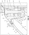
- the first wear plate 90a is positioned adjacent the first collar 106a. More specifically, the edges 102 of the first wear plate 90a are adjacent the outer portion 122 of the first collar 106a. The edges 102 may be offset from the outer portion 122 such that a weld gap 152 ( FIG. 27 ) is defined between the edge 102 and the outer portion 122. At the weld gap 152, the outer surface 74 of the drum 52 is exposed.
- the weld gap 152 may extend along the entire periphery of the outer portion 122, or the weld gap 152 may only partially extend along the periphery of the outer portion 122.
- the first wear plate 90a is immediately adjacent the first collar 106a and there is no weld gap defined between to the first wear plate 90a and the first collar 106a.
- the first wear plate 90a, the first collar 106a, and the outer surface 74 of the drum 52 may be welded together to from the rotor weldment 56.
- the welding may be accomplished with at least one weld to span the weld gap 152.
- the weld gap 152 is filled with a plurality of welds 154.
- the plurality of welds 154 may include a first weld bead 158, a second weld bead 162, and a third weld bead 166.
- the first weld bead 158 is applied between the outer portion 122 of the first collar 106a and the outer surface 74 to fix the first collar 106a to the outer surface 74.
- the second weld bead 162 is applied between the first wear plate 90a and the outer surface 74 to fix the first wear plate 90 to the outer surface 74.
- the third weld bead 166 is applied between the first weld bead 158 and the second weld bead 162 to secure the first collar 106a, the first wear plate 90a, and the outer surface 74 together.
- the first weld bead 158 and the second weld bead 162 may each be formed from multiple weld passes (e.g., weld layers).
- first weld bead 158 and the second weld bead 162 may each be formed from three weld passes.
- the weld passes may be continuous welds that extend along the entire outer periphery of the first collar 106a and the edges 102 of the first wear plate 90a.
- the weld passes may be non-continuous passes that extend along the outer periphery of the first collar 106a and the edges 102 of the first wear plate 90a.
- the weld beads 158, 162, 166 may be applied in a different order.
- the plurality of welds 154 may include more welds.
- the wear plates 90 may be directly welded to the collars 106 with minimal or no welds connecting the wear plates 90 to the outer surface 74 of the drum 52.
- FIG. 28 illustrates a rotor weldment 56' according to another embodiment.
- the rotor weldment 56' is similar to the rotor weldment 56, however the rotor weldment 56' includes a different weld pattern.
- the flange of the first collar 106a, the outer surface 74 of the drum 52, and the wear plate 90 of the rotor weldment 56' are secured or fused together by a single weld 154'.
- the single weld 154' is a single weld bead, formed in a single weld pass, that fills the entire weld gap 152.
- the single weld 154' may be achieved by applying a single weld bead on the outer surface 74 of the drum 52, the flange of the first collar 106a, and the wear plate 90 with submerged arc welding.
- FIGS. 27 and 28 illustrate the welds 154, 154' as extending along the surfaces of the drum 52, 52', the first collar 106, 106', and the wear plate 90, 90'.
- welds 154, 154' penetrate into and fuse with the base material of the drum 52, 52', the first collar 106, 106', and the wear plate 90, 90'.
- the drum 52, the collars 106, the wear plates 90, and the welds 154 form the rotor weldment 56.
- the welds 154 fuse the drum 52, the collars 106, and the wear plates 90 together to form the rotor weldment 56.
- the rotor weldment 56 is permanently coupled together.
- the hammers 58 are removably coupled to the rotor weldment 56.
- the collars 106 and the welds 154, 154' increase the strength of the drum 52. More specifically, the collars 106 and the welds 154, 154' reduce the amount of stress at the periphery of the openings 82 along the outer surface 74 of the drum 52. The collars 106 prevent the trailing edge of the openings 82 (e.g., the edge adjacent the support side 114 of the collars 106) from over stressing as the reducers 62 repeatedly impact the material.
- the rotor weldment 56 creates a load path that transfers some or a majority of the load (e.g., the stress) experienced during reduction from the reducers 62 and hammers 58, through the collar 106 (via the flange 150), to the drum 52 and/or wear plates 90.
- the load path distributes the load to the rotor weldment 56 instead of focusing the load to the periphery of the openings 82.
- the hammer 58 includes a first end 182 and a second end 186 opposite the first end 182.
- the hammer 58 has a generally rectangular shape. More specifically, the ends 182, 186 may be wider than the center portion of the hammer 58.
- the hammer 58 is positioned in the sleeve 174, which extends into the inner cavity 78 of the drum 52, and is removably coupled the first collar 106a and second collar 106b. More specifically, the first end 182 of the hammer 58 is received in the first collar 106a, and the hammer 58 extends lengthwise across the rotational axis 54 to the second collar 106b such that the second end 186 of the hammer 58 is received in the second collar 106b. In configurations where the hammer has a reducer on first end 182 and/or second end 186 a portion of the hammer 58 may be exposed (e.g., is outside of the drum 52 and collar 106a, 106b).
- the exposed portion(s) may have a cutting shape or may serve as a support or mount for a reducer 62.
- the hammer 58 has a smaller length and does not extend across the rotational axis 54 such that a first hammer is received in the first collar 106a and a second hammer is received in the second collar 106b.
- the first end 182 of the hammer 58 may be a cutting end that is configured to be removably coupled to a reducer 62.
- the reducer 62 may be removably coupled to the first end 182 by a fastener 194 (e.g., bolt or screw).
- the reducer 62 is coupled to the first end 182 with two fasteners 194.
- the fasteners 194 are inserted through the reducer 62 and into the hammer 58 in a direction that is perpendicular to the lengthwise direction of the hammer 58.
- the reducer 62 includes a sharp tool face 66.
- the tool face 66 is above the wedging side 110 of the first collar 106a such that the tool face 66 is forward facing with respect to the rotation direction 70.
- the reducer 62 can be replaced or removed from the hammer 58 by loosening the fastener 194. The reducer 62 can be removed without having to remove the hammer 58 from the collar 106 and the rotor weldment 56.
- the second end 186 of the hammer 58 may be a blank end that is not coupled to a reducer 62.
- the second end 186 is removably coupled to a cap 198 that covers the second end 186.
- the cap 198 is coupled to the second end 186 by a fastener 202 (e.g., a bolt or screw).
- the cap 198 is coupled to the second end 186 with two fasteners 202.
- the fasteners 202 are inserted through the cap 198 and into the hammer 58 in a direction that is parallel to the hammer 58.
- first end 182 and the second end 186 may both be cutting ends. In some embodiments, the first end 182 and the second end 186 may both be blank ends.
- the reducing rotor system 50 is assembled by first providing the drum 52.
- the drum 52 includes at least the first opening 82a and the second opening 82b disposed in the outer surface 74 of the drum 52.
- the first collar 106a is inserted (e.g., assembled, situated, or positioned) from an outside of the drum 52 into the first opening 82a until the inner portion 118 extends into the drum 52 and the outer portion 122, more specifically the flange 150 of the outer portion 122, extends beyond the first opening 82a and along the outer surface 74 of the drum 52.
- the sleeve 174 is inserted through the second opening 82b into the inner profile 142 of the first collar 106a such that the sleeve 174 is press fit into the first collar 106a and extends between the first opening 82a and the second opening 82b.
- the sleeve 174 may be press fit to the first collar 106a before the first collar 106a is inserted into the first opening 82a such that the sleeve 174 is inserted into the drum 52 when the first collar 106a is inserted into the drum 52.
- the sleeve 174 is aligned with the inner profile 142 of the second collar 106b such that the sleeve 174 may be press fit into the inner profile 142 when the second collar 106b is fully inserted into the opening 82b.
- the second collar 106b is inserted into the second opening 82b such that the wedging side 110 of the second collar 106b is directionally aligned in reference to the intended direction of rotation 70 with the wedging side 110 of the first collar 106a.
- the wear plates 90a-90d are situated on the outer surface 74 of the drum 52.
- the wear plates 90a-90d are situated such that the inner surface 94 of the wear plates 90a-90d abut the outer surface 74 of the drum 52 and such that the edges 102 are adjacent the outer portion 122, and more specifically the flange 150 of the outer portion 122, of the collars 106a, 106b.
- the flange 150 of the first collar 106a is welded to the outer surface 74 of the drum 52 by depositing a first weld pass to form the first weld bead 158 at the weld gap 152 between the first collar 106a and the outer surface 74.
- the outer surface 98 of the wear plate 90a is welded to the outer surface 74 of the drum 52 by depositing a second weld pass to form the second weld bead 162 at the weld gap 152 between the wear plate 90a and the outer surface 74.
- the hammer 58 is inserted into the drum 52 via the first collar 106a.
- the hammer 58 is inserted through the first collar 106a and into the sleeve 174.
- the hammer 58 is inserted until the second end 186 of the hammer 58 is received in the second collar 106b and a portion of the hammer 58 remains exposed.
- the reducer 62 is coupled to the first end 182 and the cap 198 is coupled to the second end 186.
- the reducer 62 is aligned with the hammer 58 such that the tool face 66 of the reducer 62 faces the rotation direction 70.
- the reducer 62 is coupled to the hammer 58 by inserting the fastener 194 through the reducer 62 and into the hammer 58 and tightening the fastener 194 to secure the reducer 62.
- the fastener 194 is inserted in a perpendicular direction relative to the hammer 58.
- the cap 198 is coupled to the hammer 58 by inserting the fastener 202 through the cap 198 and into the hammer 58 and tightening the fastener 202 to secure the cap 198.
- the fastener 202 is inserted in a parallel direction relative to the hammer 58.
- the first end cap 53 and the second end cap 55 can be secured to the ends of the rotor weldment 56.
- the reducing rotor system 50 can be placed into a material reducing machine such as the rotary material reducing machine 20 such that the drum rotor weldment 56 and the reducing rotor system 50 can be driven to rotate about the rotational axis 54 and the central axis 26.
- the hammers 58, along with the reducers 62 and the caps 198, are secured to the rotor weldment 56 after the rotor weldment 56 is mounted to the material reducing machine.
- one of the reducers 62 breaks or becomes worn down, one of the reducers 62 can easily be replaced by loosening the fastener 194 to decouple the reducer 62 from the hammer 58. Once the old reducer 62 is decoupled, a new reducer 62 can be coupled to the hammer 58 with the fastener 194. During the replacement of a reducer 62, the hammer 58 and the collar 106 remain secured in the drum 52.
- the hammer 58 can be easily replaced by first removing any reducers 62 or caps 198 that are coupled to the hammer 58 and then loosening the fasteners 214 in the first collar 106a and the second collar 106b. Loosening the fastener 214 unwedges the hammer 58 such that the hammer 58 can then be easily slid out of the collars 106a, 106b and the drum 52.
Landscapes
- Engineering & Computer Science (AREA)
- Food Science & Technology (AREA)
- Physics & Mathematics (AREA)
- Optics & Photonics (AREA)
- Mechanical Engineering (AREA)
- Crushing And Pulverization Processes (AREA)
- Percussive Tools And Related Accessories (AREA)
Abstract
Description
- This application claims benefit of priority to co-pending
U.S. Provisional Patent Application No. 63/512,197, filed July 6, 2023 - This present disclosure relates to material reducing machines such as grinders, shredders, and chippers.
- Material reducing machines are used to reduce the size of material such as waste material. Example waste materials include waste wood (e.g., trees, brush, stumps, pallets, railroad ties, etc.), peat moss, paper, wet organic materials, industrial waste, garbage, construction waste, and the like. A typical material reducing machine such as a grinder, a chipper, or a shredder includes a rotor to which a plurality of reducers (e.g., teeth, cutters, blades, grinding tips, chisels, etc.) are mounted. The reducers are typically mounted about the circumference of the rotor and are carried with the rotor about an axis of rotation of the rotor as the rotor is rotated. During reducing operations, the rotor is rotated, and waste material is fed adjacent to the rotor such that contact between the reducers and the waste material provides a reducing or comminuting action with respect to the waste material.
- Grinders and chippers typically are configured to reduce material through direct impact of the reducers against the material. In contrast, shredders are commonly configured such that the reducers operate in cooperation with a comb structure which intermeshes with the reducers as the rotor rotates. In the operation of a typical shredder, material fed into the shredder is forced through the comb structure by the reducers as the rotor rotates thereby providing a shredding action. It will be appreciated that during reducing operations, the rotors of grinders and chippers typically operate at higher rotational speeds than the rotors of shredders.
- The reducing rotors of material reducing machines are subjected to extreme loads. Although the loading differs, due to the differing speeds, the reducing rotor must be robustly designed to withstand the loads. Further, the reducing rotor and its attached components, such as hammers and cutters, can experience high rates of wear, particularly if the waste material is abrasive. For this reason, attached components are typically replaceable.
- In one independent aspect, a method of assembling a rotary material reduction tool includes providing a drum having an outer surface extending about a rotational axis of the drum. A collar is assembled into a first opening from an outside of the drum into the outer surface of the drum until a portion of the collar extends into the drum and a flange of the collar extends beyond the first opening and along the outer surface of the drum. The flange of the collar and the outer surface of the drum are welded together. A hammer is inserted through the collar such that a portion therefore remains exposed. The hammer is secured to the collar.
- In another independent aspect, a rotary material reduction tool has a drum, a collar, and a hammer. The drum has an outer surface that extends about a rotational axis of the drum. The drum has a first opening defined in the outer surface of the drum. The collar is received in the first opening. A first portion of the collar extends into the drum, and a flange of the collar extends beyond the first opening and along the outer surface of the drum. The hammer extends through the collar and into the drum. The hammer has an exposed portion. The flange of the collar and the outer surface of the drum are welded together.
-
-
FIG. 1 is a rear perspective view of a material reducing machine according to one embodiment of the present disclosure. -
FIG. 2 is another rear perspective view of the material reducing machine ofFIG. 1 . -
FIG. 3 is a top view of the material reducing machine ofFIG. 1 . -
FIG. 4 is a front perspective view of a reducing rotor system according to an embodiment of the present disclosure. -
FIG. 5 is a rear perspective view of the reducing rotor system ofFIG. 4 . -
FIG. 6 is a top view of the reducing rotor system ofFIG. 4 . -
FIG. 7 is a front perspective view of the reducing rotor system ofFIG. 4 with the end cap removed. -
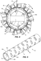
FIG. 8 is an end view of reducing rotor system ofFIG. 7 . -
FIG. 9 is a perspective view of the drum of the reducing rotor system ofFIG. 4 . -
FIG. 10 is a perspective view of a wear plate of the reducing rotor system ofFIG. 4 . -
FIG. 11 is a top view of the wear plate ofFIG. 10 . -
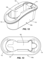
FIG. 12 is a perspective view of a collar of the reducing rotor system ofFIG. 4 . -
FIG. 13 is a top view of the collar ofFIG. 12 . -
FIG. 14 is a side view of the collar ofFIG. 12 . -
FIG. 15 is a bottom perspective view of the collar ofFIG. 12 . -
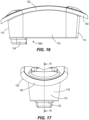
FIG. 16 is a side view of the collar ofFIG. 12 with an extension. -
FIG. 17 is an end view of the collar ofFIG. 16 . -
FIG. 18 is a bottom perspective view of the collar ofFIG. 16 . -
FIG. 19 is a cross-section of the collar taken along the line 19-19 ofFIG. 17 . -
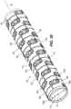
FIG. 20 is a perspective view of a rotor weldment of the reducing rotor system ofFIG. 4 . -
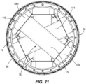
FIG. 21 is an end view of the rotor weldment ofFIG. 20 . -
FIG. 22 is a detailed view of the reducing rotor system ofFIG. 7 . -
FIG. 23 is an exploded end view of the reducing rotor system ofFIG. 22 . -
FIG. 24 is a detailed view of a portion of the exploded end view ofFIG. 23 . -
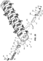
FIG. 25 is an exploded perspective view of the reducing rotor system ofFIG. 7 . -
FIG. 26 is a cross-section of the reducing rotor system taken along the line 26-26 ofFIG. 6 . -
FIG. 27 is a detailed view of a portion of the cross section ofFIG. 26 . -
FIG. 28 is a detailed view of a portion of the cross section ofFIG. 26 according to another embodiment of the present disclosure. - Before any embodiments, examples, aspects, or features are explained in detail, it is to be understood that those embodiments, examples, aspects and features are not limited in their application to the details of construction and the arrangement of components set forth in the following description or illustrated in the following drawings. Other embodiments, examples, aspects, and features are possible and are capable of being practiced or of being carried out in various ways. Also, it is to be understood that the phraseology and terminology used herein is for the purpose of description and should not be regarded as limiting.
-
FIGS. 1-3 depict amaterial reducing machine 20 that is one example of a type of material reducing machine in which a reducing rotor in accordance with the principles of the present disclosure can be incorporated. The rotarymaterial reducing machine 20 is depicted as a shredder, but it will be appreciated that aspects of the present disclosure are also applicable to other types of material reducing machines such as grinders and chippers. In one optional example, the rotarymaterial reducing machine 20 can be a relatively slow-speed shredder at which the rotor (described below in detail) is operated at speeds less than or equal to 40 rotations per minute during shredding operations. It will be appreciated that slower operating rotor speeds decrease the importance of maintaining rotor balance and therefore allow for more flexibility in selecting different reducing rotor components and configurations. It another optional example, the rotarymaterial reducing machine 20 can be a relatively fast-speed grinder or chipper at which the rotor is operated at speeds more than 40 rotations per minute during shredding operations. - The rotary
material reducing machine 20 includes a main framework defining a reducingbox 22 in which a reducingrotor 24 is positioned. The reducingrotor 24 is mounted to rotate within the reducingbox 22 about acentral axis 26. The reducingrotor 24 may be rotationally mounted to the reducingbox 22 via bearings. A plurality ofreducers 28 are mounted at an exterior of the reducingrotor 24. When the reducingrotor 24 is rotated about thecentral axis 26, thereducers 28 are carried by the reducingrotor 24 along circular reducing paths that surround thecentral axis 26. The rotarymaterial reducing machine 20 includes ahopper 30 above the reducingrotor 24 for allowing the to-be-reduced material to be fed into the reducingbox 22. Thehopper 30 optionally includes a screen (not shown) that mounts below the reducingrotor 24 for controlling the size of the reduced product which is output from the reducingbox 22. The rotarymaterial reducing machine 20 may further include a shreddingcomb 32 mounted within the reducingbox 22. The shreddingcomb 32 includes a plurality of comb teeth, and the shreddingcomb 32 is positioned relative to the reducingrotor 24 such that thereducers 28 of the reducingrotor 24 intermesh with the comb teeth of the shreddingcomb 32 as the reducingrotor 24 is rotated about thecentral axis 26. In other words, as the reducingrotor 24 rotates, thereducers 28 pass between corresponding comb teeth of the shreddingcomb 32. The rotarymaterial reducing machine 20 also includes a powertrain (not shown) for driving the rotation of the reducingrotor 24 about thecentral axis 26. The powertrain can include a prime mover (e.g., an engine) that provides the power required to drive rotation of the reducingrotor 24. The powertrain can also include a transmission for transferring the power from the prime mover to the reducingrotor 24. The power can be transferred in the form of torque. The rotarymaterial reducing machine 20 may also include one ormore conveyors 34 for transferring the reduced product discharged from the reducingbox 22 away from the reducingbox 22. - In the operation of the rotary
material reducing machine 20, material desired to be reduced is fed into the reducingbox 22 through thehopper 30. Within the reducingbox 22, the reducingrotor 24 is rotated about thecentral axis 26 by the powertrain. The material fed into the reducingbox 22 is impacted by thereducers 28 of the reducingrotor 24, and the material is forced by thereducers 28 through the shreddingcomb 32 thereby causing the material to be reduced in size via shredding. The shredded material forced through the shreddingcomb 32 can be deposited on theconveyor 34 and transferred by theconveyor 34 to a collection location such as a truck bed or a pile on the ground. If thehopper 30 includes a sizing screen below the reducingrotor 24, material that has been reduced to a size small enough to pass through the screen is deposited on theconveyor 34 while the remainder of the material is recirculated by the reducingrotor 24 back into the reducingbox 22 for further processing until it is small enough to pass through the screen. -
FIGS. 4-8 illustrate a reducingrotor system 50 having a drum 52 (e.g., a reducing rotor shown separately inFIG. 9 ) that can be integrated into a material reducing machine such as the rotarymaterial reducing machine 20. Thus, the reducingrotor system 50 is configured as a rotary material reduction tool. The reducingrotor system 50 is rotatable about a centralrotational axis 54. The reducingrotor system 50 is mountable in a material reducing machine (e.g., in the reducingbox 22 of the rotary material reducing machine 20), and when mounted in the rotarymaterial reducing machine 20, therotational axis 54 of the reducingrotor system 50 is coincident with thecentral axis 26 of the rotarymaterial reducing machine 20.Rotational axis 54 of the reducingrotor system 50 also extends through a center of thedrum 52 to form a rotation axis thereof. - The reducing
rotor system 50 includes the drum 52 (FIG. 9 ) which is part of a rotor weldment 56 (FIG. 20 ), hammers 58 that are removably coupled to therotor weldment 56, and reducers 62 (e.g., teeth, cutters, blades, etc.) that are removably coupled to thehammers 58. The reducingrotor system 50 includes afirst end cap 53 and asecond end cap 55 opposite thefirst end cap 53, portions of which may be removably coupled to the ends of therotor weldment 56. In use, the reducingrotor system 50 can be rotationally driven by a source of torque (e.g., a powertrain) to rotate about therotational axis 54. Thefirst end cap 53 of the reducingrotor system 50 is the driven end such that thefirst end cap 53 is connected to the torque source (e.g., the power train) and receives torque from the source. Thesecond end cap 55 of the reducingrotor system 50 is a mounting end that is configured to support the reducingrotor system 50 in the material reducing machine (e.g., in the reducing box 22). - The reducing
rotor system 50 is rotated about therotational axis 54 in therotation direction 70. In the illustrated embodiment, when the reducingrotor system 50 is viewed from the first end cap 53 (e.g., shown inFIG. 4 ), therotation direction 70 is clockwise. Thehammers 58 are axially positioned along the reducingrotor system 50 between thefirst end cap 53 and thesecond end cap 55. More specifically, each of thehammers 58 is located at a prescribed axial position along the length of thedrum 52. When the reducingrotor system 50 rotates about therotational axis 54, thereducers 62 travel along circular reducing paths that surround therotational axis 54. In some embodiments, thereducers 62 may be integrally formed with thehammers 58. -
FIG. 9 illustrates thedrum 52. Thedrum 52 is an elongated cylindrical structure having anouter surface 74 and aninner cavity 78. Theouter surface 74 extends from a first end of thedrum 52 to a second end of thedrum 52. The first end of thedrum 52 is adjacent thefirst end cap 53, and the second end of thedrum 52 is adjacent thesecond end cap 55. Theouter surface 74 also extends about therotational axis 54. - The
drum 52 further includes a plurality of openings 82 (e.g., collar locations) that are configured to receive thehammers 58 and additional supporting structures (described below in detail). Theopenings 82 extend from theouter surface 74 to theinner cavity 78. In the illustrated embodiment, theopenings 82 have an oval shape, however in other embodiments, theopenings 82 may have a different elongated shape (e.g., rectangular). - The
openings 82 include afirst opening 82a, asecond opening 82b, athird opening 82c, and afourth opening 82d defined in theouter surface 74 of thedrum 52. Theopenings 82 are grouped in axial sets that are spaced apart along the length of thedrum 52. A first set of openings includes thefirst opening 82a and thesecond opening 82b. The first andsecond openings drum 52. The first andsecond openings second openings second openings drum 52. In the illustrated embodiment, each of the axial set of openings includes two openings 82 (e.g., thefirst opening 82a and thesecond opening 82b), however, in other embodiments, the set of openings may includemore openings 82 that are equally spaced along the circumference of thedrum 52. In some embodiments, the set of openings may only include one opening. - The
third opening 82c and thefourth opening 82d form a second set of openings that are similar to the first set of openings (e.g., first andsecond openings - With reference to
FIGS. 4-8 and20-22 , thehammers 58 are removably coupled to thedrum 52 by a collar (e.g., a mount or a support). The reducingrotor system 50 may include a plurality ofcollars 106 that removably couple thehammers 58 to thedrum 52 and provide support to thehammers 58. Each of the collars of the plurality ofcollars 106 is at least partially received in one of theopenings 82. - The plurality of
collars 106 includes afirst collar 106a and asecond collar 106b (FIGS. 21 ,22 ). Thefirst collar 106a is at least partially received in thefirst opening 82a and thesecond collar 106b is at least partially received in thesecond opening 82b. In the illustrated embodiment, thefirst collar 106a is coupled to and supports one end of a hammer, while thesecond collar 106b is coupled to and supports the other end of the hammer. In the illustrated embodiment, thesecond collar 106b is similar to thefirst collar 106a such that only thefirst collar 106a will be described in detail. In some embodiments, thesecond collar 106b may be different than thefirst collar 106a. - With reference to
FIGS. 12-19 , thefirst collar 106a may be a monolithic body. Thefirst collar 106a may be a forged body. Thefirst collar 106a has an inner portion 118 (e.g., a first portion), an outer portion 122 (e.g., a second portion), and ahammer cavity 126 that extends between theinner portion 118 and theouter portion 122. When thefirst collar 106a is received in (e.g., positioned in or coupled to) theopening 82a, theinner portion 118 extends into thedrum 52 and theouter portion 122 extends along theouter surface 74 of thedrum 52. In the illustrated embodiment, theinner portion 118 is smaller than theopening 82a such that there is a clearance gap between theinner portion 118 and theopening 82a when thefirst collar 106a is situated in theopening 82a. In some embodiments, theinner portion 118 is the same size as theopening 82a such that theinner portion 118 is flush against theopening 82a when thefirst collar 106a is situated in theopening 82a. - The
outer portion 122 includes a flange 150 (e.g., an overhang). Theflange 150 is the widest part of thefirst collar 106a such that theflange 150 defines an outer periphery of thefirst collar 106a. The outer periphery is larger than the periphery of theopening 82a. In the illustrated embodiment, theflange 150 continuously extends along the entire periphery of thefirst collar 106a. In some embodiments, theflange 150 may only extend along a section of thefirst collar 106a. For example, theflange 150 may only extend along the ends of thefirst collar 106a, or theflange 150 may be formed from intermittent sections that span along the periphery of thecollar 106a. - The
flange 150, and the outer periphery of thefirst collar 106a form a curved surface. The curved surface has a similar (e.g., matching) curvature as theouter surface 74 of thedrum 52 such that theflange 150 extends beyond theopening 82 when thefirst collar 106a is received in theopening 82a. Theflange 150 extends along theouter surface 74 ofdrum 52. In the illustrated embodiment, there is a clearance gap between theflange 150 and theouter surface 74 of thedrum 52. In some embodiments, theflange 150 is flush against theouter surface 74 of thedrum 52. - In some embodiments (not shown), the
flange 150 includes a set of contact points (e.g., bosses, knobs, or nubs) such that when thefirst collar 106a is inserted in theopening 82a, theflange 150 only contacts theouter surface 74 of thedrum 52 at the contact points. Theflange 150 may include three or more contact points that are spaced along theflange 150. The contact points may be integrally formed with thefirst collar 106a. - The
hammer cavity 126 is configured to at least partially receive one of thehammers 58. Thehammer cavity 126 has a generally rectangular cross-section (as viewed inFIG. 13 ). In the illustrated embodiment, thehammer cavity 126 has rounded edges. Thehammer cavity 126 is dimensioned to fit one of thehammers 58. Thehammer cavity 126 may be sized only slightly larger than one of thehammers 58. Thehammer cavity 126 may be centered on thefirst collar 106a such that the center of thehammer cavity 126 is aligned with the center of thefirst collar 106a. Thehammer cavity 126 maybe formed during the forging process of thefirst collar 106a, or thehammer cavity 126 may be formed by machining (e.g., cut or bored) after thefirst collar 106a is forged. In some embodiments, thehammer cavity 126 may be off centered on thefirst collar 106a. - The
hammer cavity 126 may include an inner profile 142 (FIG. 19 ) disposed along the periphery of thehammer cavity 126. Theinner profile 142 is configured to receive a sleeve (discussed below in detail). Theinner profile 142 is positioned on a distal end of the inner portion 118 (e.g., the end of thefirst collar 106a opposite of the flange 150). Theinner profile 142 extends partially from the distal end of thefirst collar 106a toward theflange 150. Theinner profile 142 may only extend one fifth of the length of theinner portion 118. In some embodiments, theinner profile 142 may only extend one third of the length of theinner portion 118. In some embodiments, theinner profile 142 may extend the length of theinner portion 118. In some embodiments, theinner profile 142 may extend the entire length of thefirst collar 106a. - The
first collar 106a may further includes a wedging side 110 (e.g., a first side) and a support side 114 (e.g., a second side). Thehammer cavity 126 is in between the wedgingside 110 and thesupport side 114. In the illustrated embodiment, when thefirst collar 106a is positioned in theopening 82a, the wedgingside 110 is forward with respect to therotation direction 70 and thesupport side 114 is rearward with respect to therotation direction 70. In some embodiments, thesupport side 114 may be forward with respect to therotation direction 70. In some embodiments, thefirst collar 106a may include two wedging sides 110 (e.g., a front wedging side and a rear wedging side) and no support side. In some embodiments, thefirst collar 106a may include two support sides 114 (e.g., a front support side and a rear support side) and no wedging side. - The wedging
side 110 includes a wedgingcavity 130 that extends into the length of thefirst collar 106a. The wedgingcavity 130 and thehammer cavity 126 may be open to each other either directly or indirectly. The wedgingcavity 130 and thehammer cavity 126 may be directly adjacent and directly open to each other. In the illustrated embodiment, the wedgingcavity 130 is continuous (e.g., fluidly connected) with thehammer cavity 126. The wedgingcavity 130 may be formed during the forging process of thefirst collar 106a, or the wedgingcavity 130 may be formed by machining (e.g., cut, or bored) after thefirst collar 106a is forged. In some embodiments, the wedgingcavity 130 may only partially extend the length of thefirst collar 106a. - With reference to
FIGS. 24 and27 , a wedgingassembly 204 is disposed in thewedging cavity 130. The wedgingassembly 204 removably secures thehammer 58 to thefirst collar 106a. The operation of the wedgingassembly 204 applies a force onto thehammer 58 that is perpendicular to the length of thehammer 58 in order to pinch or wedge thehammer 58 to thefirst collar 106a. The wedgingassembly 204 may include afirst wedge 208, asecond wedge 212, and a fastener 214 (e.g., a bolt). Thefastener 214 extends through thefirst wedge 208 and through thesecond wedge 212. Thefastener 214 does not extend through thehammer 58 or thereducer 62. - The
first wedge 208 includes arecess 218, anangled contact face 221, and awedge surface 223. The recess is configured to receive a portion of thefastener 214. Thewedge surface 223 is opposite theangled contact face 221. Thewedge surface 223 is adjacent thecollar 106. - The
second wedge 212 has an L-shape. Thesecond wedge 212 includes abase 228, anangled contact face 232, and awedge surface 234. Thebase 228 includes arecess 225 that receives a portion of thefastener 214. Thebase 228 is positioned below thefirst wedge 208. Theangled contact face 232 is positioned between theangled contact face 221 of thefirst wedge 208 and thehammer 58. Theangled contact face 232 of thesecond wedge 212 is configured to engage with theangled contact face 232 of thefirst wedge 208. Thewedge surface 234 is opposite theangled contact face 232. Thewedge surface 234 is adjacent thehammer 58 and applies a force to thehammer 58. The force is perpendicular to the length of thehammer 58. - The
fastener 214 is received in both thefirst wedge 208 and thesecond wedge 212 and is threadingly received by anut 235. In some constructions, thenut 235 is T-shaped. Thenut 235 is positioned below both thefirst wedge 208 and thesecond wedge 212. The wedgingcavity 130 may have aprojection 236 that separates thewedges nut 235 and limits the axial movement of thenut 235. In other embodiments, thenut 235 may be a hex-nut or a square nut. - As the
fastener 214 is tightened into thenut 235, it causes thefirst wedge 208 to engage with thesecond wedge 212. More specifically, tightening thefastener 214 pushes thefirst wedge 208 downward (e.g., toward the inner cavity 78) and causes theangled contact face 232 of thefirst wedge 208 to engage with theangled contact face 232 of thesecond wedge 212. Thefirst wedge 208 pushes thewedge surface 234 of thesecond wedge 212 laterally against thehammer 58 such that the hammer is secured (e.g., wedged, or pinched) into thefirst collar 106a and cannot be removed. When thefastener 214 is loosened, it allows thefirst wedge 208 to disengage with thesecond wedge 212. Thefirst wedge 208 is relaxed such that thefirst wedge 208 may exert less of a force onto thesecond wedge 212. Thehammer 58 is no longer secured such that it can be removed from thefirst collar 106a. - The wedging
side 110 may also include anextension 134. Theextension 134 extends past thesupport side 114. Theextension 134 includes acap 238 and aspacer 242 that extend the length of the wedgingcavity 130. Thecap 238 is configured to cover thewedging cavity 130 and prevents thenut 235 from falling into theinner cavity 78 of thedrum 52. Thespacer 242 allows thefastener 214 and thenut 235 to be positioned in thewedging cavity 130 and allows extra room for thefastener 214 to move downward. - The
spacer 242 is welded to the distal end of the wedgingside 110 by aweld 246. Thecap 238 is welded to thespacer 242 by aweld 250. In some embodiments, thespacer 242 and thecap 238 are a unitary piece. In some embodiments, thespacer 242 and thecap 238 are included in the monolithic forging of thefirst collar 106a. - The
support side 114 provides strength to thefirst collar 106a. Thesupport side 114 is an entirely solid structure and does not have any openings. Thesupport side 114 does not have any removable pieces or elements. - With reference to
FIGS. 20-27 , the reducingrotor system 50 may include asleeve 174 that is coupled to thefirst collar 106a and thesecond collar 106b. More specifically, thesleeve 174 may be press fit into theinner profile 142 of thefirst collar 106a and thesecond collar 106b. Thesleeve 174 is a rectangular extension that is configured to receive a hammer. Thesleeve 174 has a constant rectangular cross section. Thesleeve 174 extends through theinner cavity 78 of the drum and at least partially between thefirst opening 82a and thesecond opening 82b. More specifically, thesleeve 174 extends between thefirst collar 106a and thesecond collar 106b. Thesleeve 174 prevents objects (e.g., hammers, dirt, chipped material, etc.) from accidently falling into theinner cavity 78 of thedrum 52 which may be inaccessible once assembled in a material reducing machine. - Additionally, the
sleeve 174 may be used during assembly ofrotor weldment 56 to create the clearance gap between thecollars outer surface 74 of thedrum 58. More specifically, the length of thesleeve 174 can be selected to create the gap and control the size of the gap between thecollars outer surface 74. A first end ofsleeve 174 is received in theinner profile 142 of thefirst collar 106a and a second end of thesleeve 174 is received in theinner profile 142 of thesecond collar 106b. The length of thesleeve 174 separates thefirst collar 106a and thesecond collar 106b apart from each other. To set an increased distance between thefirst collar 106a and thesecond collar 106b, thesleeve 174 may be increased in length. To set a decreased distance between thefirst collar 106a and thesecond collar 106b, thesleeve 174 may be decreased in length. The length of thesleeve 174 is selected to achieve the desired gap between thefirst collar 106a and the outer surface 72 and the desired gap between thesecond collar 106b and the outer surface 72. The desired gaps allow for a more controlled and consistent weld (discussed below in detail). - With reference to
FIGS. 6 ,10 ,11 , and20 , therotor weldment 56 may include a plurality of wear plates 90 (e.g., a plating or a shell) that extend along theouter surface 74 of thedrum 52. The plurality ofwear plates 90 is fixed to theouter surface 74 of thedrum 52. More specifically, the plurality ofwear plates 90 is welded to theouter surface 74 of thedrum 52. The plurality ofwear plates 90 may be formed from a material that is harder than theouter surface 74. The material of thewear plates 90 may be Hardox® 500 abrasion resistant steel. Alternatively, thewear plates 90 may be construed of another suitable abrasion resistant steel. The plurality ofwear plates 90 increases the strength and wear resistance of therotor weldment 56 as compared to thedrum 52 alone. - In the illustrated embodiment, the plurality of
wear plates 90 includes afirst wear plate 90a, asecond wear plate 90b, athird wear plate 90c, and afourth wear plate 90d. Thefirst wear plate 90a is circumferentially adjacent thesecond wear plate 90c, and thethird wear plate 90c is circumferentially adjacent thefourth wear plate 90d. Thefirst wear plate 90a is axially adjacent to thethird wear plate 90c, and thesecond wear plate 90d is axially adjacent to thefourth wear plate 90d. In the illustrated embodiment, thewear plates 90a-90d are all similar, such that only thefirst wear plate 90a will be described in detail. - The
first wear plate 90a includes aninner surface 94, anouter surface 98, and at least onecurved edge 102. When thefirst wear plate 90a is positioned on thedrum 52, theinner surface 94 of thefirst wear plate 90a abuts theouter surface 74 of thedrum 52 and is flush against theouter surface 74. Thefirst wear plate 90a defines a curvedinner surface 94. In the illustrated embodiment, theinner surface 94 has a semi-circular shape. Thesecond wear plate 90b is positioned circumferentially adjacent to thefirst wear plate 90a to cover the circumference of thedrum 52. The circumferentially adjacent wear plates (e.g., thefirst wear plate 90a and thesecond wear plate 90b) may abut each other, or there may be a gap defined between thewear plates drum 52. Similar to theopenings 82, the first andsecond wear plates fourth wear plates FIG. 20 . In the illustrated embodiment, the sets of wear plates are offset by 60 degrees. In some embodiments, the angular offset amount may be more or less. - The
first wear plate 90a has twocurved edges 102. When thefirst wear plate 90a is positioned on thedrum 52, thecurved edges 102 are positioned adjacent a corresponding portion of theopenings 82 of thedrum 52. Said another way, theedges 102 follow a contour of part of theopenings 82. In the illustrated embodiment, theedges 102 have a semi-oval shape such that two wear plates form an oval opening that follows the contour of one of theopenings 82 or follows the contour of one of thecollars 106. For example, with reference toFIG. 6 , an oval opening is formed between thefirst wear plate 90a having anedge 102a and thefourth wear plate 90d having anedge 102d. In some embodiments, thefirst wear plate 90a has an opening that is oval shaped such that only one wear plate (e.g., thefirst wear plate 90a) is needed to create the opening that corresponds with theopening 82. In some embodiments, thewear plates 90 may have welding tabs that extend from thewear plate 90 and allow for welding on the tabs. - The
wear plates 90 may be positioned adjacent thecollars 106 while allowing for a clearance for welding between thewear plates 90 and thecollars 106. For example, in the illustrated embodiment, thefirst wear plate 90a is positioned adjacent thefirst collar 106a. More specifically, theedges 102 of thefirst wear plate 90a are adjacent theouter portion 122 of thefirst collar 106a. Theedges 102 may be offset from theouter portion 122 such that a weld gap 152 (FIG. 27 ) is defined between theedge 102 and theouter portion 122. At theweld gap 152, theouter surface 74 of thedrum 52 is exposed. Theweld gap 152 may extend along the entire periphery of theouter portion 122, or theweld gap 152 may only partially extend along the periphery of theouter portion 122. In some embodiments, thefirst wear plate 90a is immediately adjacent thefirst collar 106a and there is no weld gap defined between to thefirst wear plate 90a and thefirst collar 106a. - With reference to
FIG. 27 , at theweld gap 152 thefirst wear plate 90a, thefirst collar 106a, and theouter surface 74 of thedrum 52 may be welded together to from therotor weldment 56. The welding may be accomplished with at least one weld to span theweld gap 152. In the illustrated embodiment, theweld gap 152 is filled with a plurality ofwelds 154. The plurality ofwelds 154 may include afirst weld bead 158, asecond weld bead 162, and athird weld bead 166. Thefirst weld bead 158 is applied between theouter portion 122 of thefirst collar 106a and theouter surface 74 to fix thefirst collar 106a to theouter surface 74. Thesecond weld bead 162 is applied between thefirst wear plate 90a and theouter surface 74 to fix thefirst wear plate 90 to theouter surface 74. Thethird weld bead 166 is applied between thefirst weld bead 158 and thesecond weld bead 162 to secure thefirst collar 106a, thefirst wear plate 90a, and theouter surface 74 together. Thefirst weld bead 158 and thesecond weld bead 162 may each be formed from multiple weld passes (e.g., weld layers). For example, thefirst weld bead 158 and thesecond weld bead 162 may each be formed from three weld passes. The weld passes may be continuous welds that extend along the entire outer periphery of thefirst collar 106a and theedges 102 of thefirst wear plate 90a. In some embodiments, the weld passes may be non-continuous passes that extend along the outer periphery of thefirst collar 106a and theedges 102 of thefirst wear plate 90a. In some embodiments, theweld beads welds 154 may include more welds. In some embodiments, thewear plates 90 may be directly welded to thecollars 106 with minimal or no welds connecting thewear plates 90 to theouter surface 74 of thedrum 52. -
FIG. 28 illustrates a rotor weldment 56' according to another embodiment. The rotor weldment 56' is similar to therotor weldment 56, however the rotor weldment 56' includes a different weld pattern. The flange of thefirst collar 106a, theouter surface 74 of thedrum 52, and thewear plate 90 of the rotor weldment 56' are secured or fused together by a single weld 154'. The single weld 154' is a single weld bead, formed in a single weld pass, that fills theentire weld gap 152. The single weld 154' may be achieved by applying a single weld bead on theouter surface 74 of thedrum 52, the flange of thefirst collar 106a, and thewear plate 90 with submerged arc welding. -
FIGS. 27 and28 illustrate thewelds 154, 154' as extending along the surfaces of thedrum 52, 52', thefirst collar 106, 106', and thewear plate 90, 90'. However, one skilled in the art of welding would recognize that thewelds 154, 154' penetrate into and fuse with the base material of thedrum 52, 52', thefirst collar 106, 106', and thewear plate 90, 90'. - With reference to
FIGS. 20 and21 , thedrum 52, thecollars 106, thewear plates 90, and thewelds 154 form therotor weldment 56. Thewelds 154 fuse thedrum 52, thecollars 106, and thewear plates 90 together to form therotor weldment 56. Therotor weldment 56 is permanently coupled together. Thehammers 58 are removably coupled to therotor weldment 56. - The
collars 106 and thewelds 154, 154' increase the strength of thedrum 52. More specifically, thecollars 106 and thewelds 154, 154' reduce the amount of stress at the periphery of theopenings 82 along theouter surface 74 of thedrum 52. Thecollars 106 prevent the trailing edge of the openings 82 (e.g., the edge adjacent thesupport side 114 of the collars 106) from over stressing as thereducers 62 repeatedly impact the material. Therotor weldment 56 creates a load path that transfers some or a majority of the load (e.g., the stress) experienced during reduction from thereducers 62 and hammers 58, through the collar 106 (via the flange 150), to thedrum 52 and/or wearplates 90. The load path distributes the load to therotor weldment 56 instead of focusing the load to the periphery of theopenings 82. - With reference to
FIG. 24 , thehammer 58 includes afirst end 182 and asecond end 186 opposite thefirst end 182. In the illustrated embodiment, thehammer 58 has a generally rectangular shape. More specifically, theends hammer 58. - During assembly, the
hammer 58 is positioned in thesleeve 174, which extends into theinner cavity 78 of thedrum 52, and is removably coupled thefirst collar 106a andsecond collar 106b. More specifically, thefirst end 182 of thehammer 58 is received in thefirst collar 106a, and thehammer 58 extends lengthwise across therotational axis 54 to thesecond collar 106b such that thesecond end 186 of thehammer 58 is received in thesecond collar 106b. In configurations where the hammer has a reducer onfirst end 182 and/or second end 186 a portion of thehammer 58 may be exposed (e.g., is outside of thedrum 52 andcollar reducer 62. In some embodiments, thehammer 58 has a smaller length and does not extend across therotational axis 54 such that a first hammer is received in thefirst collar 106a and a second hammer is received in thesecond collar 106b. - The
first end 182 of thehammer 58 may be a cutting end that is configured to be removably coupled to areducer 62. Thereducer 62 may be removably coupled to thefirst end 182 by a fastener 194 (e.g., bolt or screw). In the illustrated embodiment, thereducer 62 is coupled to thefirst end 182 with twofasteners 194. Thefasteners 194 are inserted through thereducer 62 and into thehammer 58 in a direction that is perpendicular to the lengthwise direction of thehammer 58. Thereducer 62 includes asharp tool face 66. Thetool face 66 is above the wedgingside 110 of thefirst collar 106a such that thetool face 66 is forward facing with respect to therotation direction 70. Thereducer 62 can be replaced or removed from thehammer 58 by loosening thefastener 194. Thereducer 62 can be removed without having to remove thehammer 58 from thecollar 106 and therotor weldment 56. - With reference to
FIGS. 23 ,25 , and26 , thesecond end 186 of thehammer 58 may be a blank end that is not coupled to areducer 62. Thesecond end 186 is removably coupled to acap 198 that covers thesecond end 186. Thecap 198 is coupled to thesecond end 186 by a fastener 202 (e.g., a bolt or screw). In the illustrated embodiment, thecap 198 is coupled to thesecond end 186 with twofasteners 202. Thefasteners 202 are inserted through thecap 198 and into thehammer 58 in a direction that is parallel to thehammer 58. - In some embodiments, the
first end 182 and thesecond end 186 may both be cutting ends. In some embodiments, thefirst end 182 and thesecond end 186 may both be blank ends. - Additionally, a detailed description of a hammer that may be similar to the
hammer 58 is provided inU.S. Patent No. 11,338,298 - The reducing
rotor system 50 is assembled by first providing thedrum 52. Thedrum 52 includes at least thefirst opening 82a and thesecond opening 82b disposed in theouter surface 74 of thedrum 52. - Then, the
first collar 106a is inserted (e.g., assembled, situated, or positioned) from an outside of thedrum 52 into thefirst opening 82a until theinner portion 118 extends into thedrum 52 and theouter portion 122, more specifically theflange 150 of theouter portion 122, extends beyond thefirst opening 82a and along theouter surface 74 of thedrum 52. Thesleeve 174 is inserted through thesecond opening 82b into theinner profile 142 of thefirst collar 106a such that thesleeve 174 is press fit into thefirst collar 106a and extends between thefirst opening 82a and thesecond opening 82b. In some embodiments, thesleeve 174 may be press fit to thefirst collar 106a before thefirst collar 106a is inserted into thefirst opening 82a such that thesleeve 174 is inserted into thedrum 52 when thefirst collar 106a is inserted into thedrum 52. - Next, the
second collar 106b is inserted (e.g., situated) into thesecond opening 82b until theinner portion 118 extends into thedrum 52 and theouter portion 122, more specifically theflange 150 of theouter portion 122, abuts theouter surface 74 of thedrum 52. Thesecond collar 106b is aligned with thefirst collar 106a and thesleeve 174 such that thesecond collar 106b is coupled to thesleeve 174. More specifically, while thesecond collar 106b is being inserted in thesecond opening 82b, thesleeve 174 is aligned with theinner profile 142 of thesecond collar 106b such that thesleeve 174 may be press fit into theinner profile 142 when thesecond collar 106b is fully inserted into theopening 82b. Thesecond collar 106b is inserted into thesecond opening 82b such that the wedgingside 110 of thesecond collar 106b is directionally aligned in reference to the intended direction ofrotation 70 with the wedgingside 110 of thefirst collar 106a. - Once the
first collar 106a and thesecond collar 106b are situated in theirrespective openings wear plates 90a-90d are situated on theouter surface 74 of thedrum 52. Thewear plates 90a-90d are situated such that theinner surface 94 of thewear plates 90a-90d abut theouter surface 74 of thedrum 52 and such that theedges 102 are adjacent theouter portion 122, and more specifically theflange 150 of theouter portion 122, of thecollars wear plates 90a-90b are also positioned such that they are offset from theouter portion 122 of thecollars weld gap 152 is formed between thecollars wear plates 90a-90d. - Then, the
first collar 106a, thesecond collar 106b, and thewear plates 90a-90d are secured to theouter surface 74 of thedrum 52 to form therotor weldment 56. More specifically, thefirst collar 106a, thesecond collar 106b, and thewear plates 90a-90d are welded to theouter surface 74 of thedrum 52. Even more specifically, theflange 150 of thefirst collar 106a, theflange 150 of thesecond collar 106b, and theouter surface 98 of thewear plates 90a-90d are welded to theouter surface 74 of thedrum 52. Welding thefirst collar 106a, thesecond collar 106b, and thewear plates 90a-90d may include depositing multiple passes in theweld gap 152. More specifically, theflange 150 of thefirst collar 106a is welded to theouter surface 74 of thedrum 52 by depositing a first weld pass to form thefirst weld bead 158 at theweld gap 152 between thefirst collar 106a and theouter surface 74. Then, theouter surface 98 of thewear plate 90a is welded to theouter surface 74 of thedrum 52 by depositing a second weld pass to form thesecond weld bead 162 at theweld gap 152 between thewear plate 90a and theouter surface 74. Finally, thefirst collar 106a, thewear plate 90a, and theouter surface 74 are welded together by depositing a third weld pass to from thethird weld bead 166 between thefirst weld bead 158 and thesecond weld bead 162 at theweld gap 152. A similar welding process may be repeated on the other side of thedrum 52 to secure thesecond collar 106b and thesecond wear plate 90b to theouter surface 74 of thedrum 52. As noted above, different weld configurations may be used in forming therotor weldment 56. - Once the
rotor weldment 56 is formed, thehammer 58 is inserted into thedrum 52 via thefirst collar 106a. Thehammer 58 is inserted through thefirst collar 106a and into thesleeve 174. Thehammer 58 is inserted until thesecond end 186 of thehammer 58 is received in thesecond collar 106b and a portion of thehammer 58 remains exposed. - The
hammer 58 is then secured to thefirst collar 106a and thesecond collar 106b. Thehammer 58 is secured to thefirst collar 106a by tightening thefastener 214 to pushfirst wedge 208 and thewedge surface 234 of thesecond wedge 212 against the wedgingside 110 of thehammer 58. As thefastener 214 is being tightened, thefastener 214 moves downward (e.g., toward the inner cavity 78) and pushes thefirst wedge 208 downward. Theangled contact face 221 of thefirst wedge 208 wedges against theangled contact face 232 of thesecond wedge 212 thereby securing and pinching thehammer 58 to thefirst collar 106a. A similar wedging process may be repeated on the other side of thedrum 52 to secure thehammer 58 to thesecond collar 106b and thedrum 52. - Once the
hammer 58 is secured to thefirst collar 106a and thesecond collar 106b, thereducer 62 is coupled to thefirst end 182 and thecap 198 is coupled to thesecond end 186. Thereducer 62 is aligned with thehammer 58 such that thetool face 66 of thereducer 62 faces therotation direction 70. Thereducer 62 is coupled to thehammer 58 by inserting thefastener 194 through thereducer 62 and into thehammer 58 and tightening thefastener 194 to secure thereducer 62. Thefastener 194 is inserted in a perpendicular direction relative to thehammer 58. On thesecond end 186, thecap 198 is coupled to thehammer 58 by inserting thefastener 202 through thecap 198 and into thehammer 58 and tightening thefastener 202 to secure thecap 198. Thefastener 202 is inserted in a parallel direction relative to thehammer 58. - Once the
reducer 62 and thecap 198 are secured to thehammer 58, thefirst end cap 53 and thesecond end cap 55 can be secured to the ends of therotor weldment 56. Once the end caps 53, 55 are secured to therotor weldment 56, the reducingrotor system 50 can be placed into a material reducing machine such as the rotarymaterial reducing machine 20 such that thedrum rotor weldment 56 and the reducingrotor system 50 can be driven to rotate about therotational axis 54 and thecentral axis 26. In some embodiments, thehammers 58, along with thereducers 62 and thecaps 198, are secured to therotor weldment 56 after therotor weldment 56 is mounted to the material reducing machine. - If one of the
reducers 62 breaks or becomes worn down, one of thereducers 62 can easily be replaced by loosening thefastener 194 to decouple thereducer 62 from thehammer 58. Once theold reducer 62 is decoupled, anew reducer 62 can be coupled to thehammer 58 with thefastener 194. During the replacement of areducer 62, thehammer 58 and thecollar 106 remain secured in thedrum 52. - If the
hammer 58 becomes worn down, breaks, or needs to be inspected, thehammer 58 can be easily replaced by first removing anyreducers 62 orcaps 198 that are coupled to thehammer 58 and then loosening thefasteners 214 in thefirst collar 106a and thesecond collar 106b. Loosening thefastener 214 unwedges thehammer 58 such that thehammer 58 can then be easily slid out of thecollars drum 52. - Although the assembly method of the reducing
rotor system 50 is described in sequential steps, it will be appreciated that some of the steps may be completed in a different order, some of the steps may be completed simultaneously, and some of the steps may be omitted. - In addition, unless the context of their usage unambiguously indicates otherwise, the articles "a" and "an" should not be interpreted as meaning "one" or "only one." Rather these articles should be interpreted as meaning "at least one" or "one or more."
- Although certain embodiments, examples, features, and aspects have been described and illustrated, variations and modifications exist within the scope and spirit of the subject matter explained and shown.
Preferred features of the invention: - 1. A method of assembling a rotary material reduction tool, comprising:
- providing a drum having an outer surface extending about a rotational axis of the drum;
- assembling a collar from an outside of the drum into a first opening in the outer surface of the drum until a portion of the collar extends into the drum and a flange of the collar extends beyond the first opening and along the outer surface of the drum;
- welding the flange of the collar and the outer surface of the drum together;
- inserting a hammer through the collar such that a portion of the hammer remains exposed; and
- securing the hammer to the collar.
- 2. The method of clause 1, wherein welding the flange of the collar and the outer surface of the drum together includes depositing multiple weld passes.
- 3. The method of clause 1, further comprising situating a second collar into a second opening in the outer surface of the drum until a portion of the second collar extends into the drum and a flange of the second collar extends beyond the first opening and along the outer surface of the drum, wherein the second opening is opposite the first opening.
- 4. The method of clause 3, further comprising press fitting a sleeve into the collar, the sleeve extending between the collar and the second collar.
- 5. The method of clause 1, wherein the hammer is secured to the collar by tightening a fastener into one side of the collar to wedge the hammer into the collar.
- 6. The method of clause 1, further comprising securing a wear plate to the outer surface of the drum.
- 7. The method of clause 6, wherein the wear plate is secured to the outer surface of the drum by welding.
- 8. The method of clause 7, wherein the welding the flange of the collar and the outer surface of the drum together includes depositing a first weld pass, and the welding the wear plate and the outer surface of the drum together includes depositing a second weld pass, the method further comprising depositing at least one additional weld pass between the first weld pass and the second weld pass.
- 9. The method of clause 7, wherein the welding the flange of the collar and the outer surface of the drum together and the welding the wear plate and the outer surface of the drum together includes applying a single weld pass between the flange of the collar, the outer surface of the drum, and the wear plate.
- 10. A rotary material reduction tool comprising:
- a drum having an outer surface extending about a rotational axis of the drum, the drum having a first opening defined in the outer surface of the drum;
- a collar received in the first opening, wherein a first portion of the collar extends into the drum and a flange of the collar extends beyond the first opening and along the outer surface of the drum; and
- a hammer extending through the collar and into the drum, the hammer having an exposed portion,
- wherein the flange of the collar and the outer surface of the drum are welded together.
- 11. The rotary material reduction tool of clause 10, further comprising a second collar coupled to a second opening in the outer surface of the drum, the second opening is opposite the first opening, a first portion of the second collar extending into the drum and a flange of the second collar extending outside the drum.
- 12. The rotary material reduction tool of clause 10, further comprising a wear plate secured to on the outer surface of the drum.
- 13. The rotary material reduction tool of clause 12, wherein the collar, the wear plate, and the outer surface of the drum are welded together.
- 14. The rotary material reduction tool of clause 10, wherein an outer periphery of the collar forms a curved surface.
- 15. The rotary material reduction tool of clause 10, wherein the flange extends beyond an entire periphery of the first opening.
- 16. The rotary material reduction tool of clause 10, further comprising a sleeve extending at least partially between the first opening and a second opening in the outer surface, the second opening is opposite the first opening, and the hammer is at least partially positioned within the sleeve.
- 17. The rotary material reduction tool of clause 10, wherein the collar includes a wedging side and a support side, wherein the wedging side includes a fastener and a wedging assembly, the wedging assembly securing the hammer to the collar when the fastener is secured.
- 18. The rotary material reduction tool of clause 17, wherein the support side is an entirely solid structure, without any openings.
- 19. The rotary material reduction tool of clause 10, wherein the collar is a monolithic forging.
- 20. The rotary material reduction tool of clause 10, wherein the hammer extends across the rotational axis.
Claims (15)
- A method of assembling a rotary material reduction tool, comprising:providing a drum having an outer surface extending about a rotational axis of the drum;assembling a collar from an outside of the drum into a first opening in the outer surface of the drum until a portion of the collar extends into the drum and a flange of the collar extends beyond the first opening and along the outer surface of the drum;welding the flange of the collar and the outer surface of the drum together;inserting a hammer through the collar such that a portion of the hammer remains exposed; andsecuring the hammer to the collar.
- The method of claim 1, wherein welding the flange of the collar and the outer surface of the drum together includes depositing multiple weld passes.
- The method of claim 1 or 2, further comprising situating a second collar into a second opening in the outer surface of the drum until a portion of the second collar extends into the drum and a flange of the second collar extends beyond the first opening and along the outer surface of the drum, wherein the second opening is opposite the first opening.
- The method of claim 3, further comprising press fitting a sleeve into the collar, the sleeve extending between the collar and the second collar.
- The method of any preceding claim, wherein the hammer is secured to the collar by tightening a fastener into one side of the collar to wedge the hammer into the collar.
- The method of any preceding claim, further comprising securing a wear plate to the outer surface of the drum, and the wear plate is preferably secured to the outer surface of the drum by welding.
- The method of claim 6, wherein the collar, the wear plate, and the outer surface of the drum are welded together.
- A rotary material reduction tool comprising:a drum having an outer surface extending about a rotational axis of the drum, the drum having a first opening defined in the outer surface of the drum;a collar received in the first opening, wherein a first portion of the collar extends into the drum and a flange of the collar extends beyond the first opening and along the outer surface of the drum; anda hammer extending through the collar and into the drum, the hammer having an exposed portion,wherein the flange of the collar and the outer surface of the drum are welded together.
- The rotary material reduction tool of claim 8, further comprising a second collar coupled to a second opening in the outer surface of the drum, the second opening is opposite the first opening, a first portion of the second collar extending into the drum and a flange of the second collar extending outside the drum.
- The rotary material reduction tool of claim 8 or 9, further comprising a wear plate secured to on the outer surface of the drum, and preferably wherein the collar, the wear plate, and the outer surface of the drum are welded together.
- The rotary material reduction tool of any one of claims 8 to 10, wherein an outer periphery of the collar forms a curved surface.
- The rotary material reduction tool of any one of claims 8 to 11, wherein the flange extends beyond an entire periphery of the first opening.
- The rotary material reduction tool of any one of claims 8 to 12, further comprising a sleeve extending at least partially between the first opening and a second opening in the outer surface, the second opening is opposite the first opening, and the hammer is at least partially positioned within the sleeve.
- The rotary material reduction tool of any one of claims 8 to 13, wherein the collar includes a wedging side and a support side, wherein the wedging side includes a fastener and a wedging assembly, the wedging assembly securing the hammer to the collar when the fastener is secured, and preferably wherein the support side is an entirely solid structure, without any openings.
- The rotary material reduction tool of any one of claims 8 to 14, wherein the collar is a monolithic forging.
Applications Claiming Priority (1)
| Application Number | Priority Date | Filing Date | Title |
|---|---|---|---|
| US202363512197P | 2023-07-06 | 2023-07-06 |
Publications (1)
| Publication Number | Publication Date |
|---|---|
| EP4487960A1 true EP4487960A1 (en) | 2025-01-08 |
Family
ID=91738233
Family Applications (1)
| Application Number | Title | Priority Date | Filing Date |
|---|---|---|---|
| EP24185418.1A Pending EP4487960A1 (en) | 2023-07-06 | 2024-06-28 | Rotary material reduction tool |
Country Status (5)
| Country | Link |
|---|---|
| US (1) | US20250010307A1 (en) |
| EP (1) | EP4487960A1 (en) |
| JP (1) | JP2025010119A (en) |
| CN (1) | CN119260401A (en) |
| CA (1) | CA3244713A1 (en) |
Citations (4)
| Publication number | Priority date | Publication date | Assignee | Title |
|---|---|---|---|---|
| EP1028808B1 (en) * | 1997-09-10 | 2006-11-08 | Mesa Reduction Engineering & Processing, Inc. | System and method for reducing material |
| US20140239105A1 (en) * | 2012-01-20 | 2014-08-28 | Scott Equipment Company | Paddle assembly |
| WO2015038619A1 (en) * | 2013-09-10 | 2015-03-19 | Vermeer Manufacturing Company | Hammer support for rotary tool |
| US11338298B2 (en) | 2018-12-20 | 2022-05-24 | Vermeer Manufacturing Company | Material reducing apparatus having a system for allowing a reducing rotor to be selectively configured in multiple different reducing configurations |
Family Cites Families (3)
| Publication number | Priority date | Publication date | Assignee | Title |
|---|---|---|---|---|
| DE4343801A1 (en) * | 1993-12-22 | 1995-06-29 | Lindemann Maschfab Gmbh | Shredding machine with rotor |
| US5873534A (en) * | 1997-10-31 | 1999-02-23 | Shinn; Rickey D. | Cutter tooth holder assembly |
| US6840471B2 (en) * | 2000-02-25 | 2005-01-11 | Vermeer Manufacturing Company | Rotary grinder apparatus and method |
-
2024
- 2024-06-28 CA CA3244713A patent/CA3244713A1/en active Pending
- 2024-06-28 EP EP24185418.1A patent/EP4487960A1/en active Pending
- 2024-07-02 US US18/762,185 patent/US20250010307A1/en active Pending
- 2024-07-04 CN CN202410892317.4A patent/CN119260401A/en active Pending
- 2024-07-05 JP JP2024108694A patent/JP2025010119A/en active Pending
Patent Citations (4)
| Publication number | Priority date | Publication date | Assignee | Title |
|---|---|---|---|---|
| EP1028808B1 (en) * | 1997-09-10 | 2006-11-08 | Mesa Reduction Engineering & Processing, Inc. | System and method for reducing material |
| US20140239105A1 (en) * | 2012-01-20 | 2014-08-28 | Scott Equipment Company | Paddle assembly |
| WO2015038619A1 (en) * | 2013-09-10 | 2015-03-19 | Vermeer Manufacturing Company | Hammer support for rotary tool |
| US11338298B2 (en) | 2018-12-20 | 2022-05-24 | Vermeer Manufacturing Company | Material reducing apparatus having a system for allowing a reducing rotor to be selectively configured in multiple different reducing configurations |
Also Published As
| Publication number | Publication date |
|---|---|
| JP2025010119A (en) | 2025-01-20 |
| US20250010307A1 (en) | 2025-01-09 |
| CN119260401A (en) | 2025-01-07 |
| CA3244713A1 (en) | 2025-06-09 |
Similar Documents
| Publication | Publication Date | Title |
|---|---|---|
| US5547136A (en) | Rotary grinding apparatus for recycling waste materials | |
| CN111346706B (en) | Material decomposing system and material decomposing machine | |
| US8113453B2 (en) | Reducing machine rotor assembly and methods of constructing and operating the same | |
| US8104701B2 (en) | Apparatus and method for supporting a removable anvil | |
| US4901929A (en) | Rotary shearing wheel with individually replaceable cutting segments | |
| US20020125353A1 (en) | Reducing machine rotor assembly and methods of constructiing and operating the same | |
| US4776249A (en) | Resharpenable rotary shearing apparatus | |
| EP1697051A1 (en) | A tooth construction for a mineral breaker | |
| US20040217223A1 (en) | Grinder cutter tooth and anvil assembly | |
| US8038088B2 (en) | Comminuting device with counter-rotating rotors | |
| US11084043B2 (en) | Impact cutter blade and holder system and method | |
| US20250010307A1 (en) | Rotary material reduction tool | |
| US7172147B2 (en) | Modular blade assembly with alignment means | |
| US6196284B1 (en) | Wood pulverizer with improved grates and grate components | |
| US20130341449A1 (en) | Anvil unit for a material reducing machine | |
| JP3045727B1 (en) | Shear crusher | |
| JP2005059106A (en) | Method for replacing blade of apparatus for producing solid fuel from waste and jig used therefor | |
| JP3222843B2 (en) | Crushing machine | |
| US6012663A (en) | Modular cutting system and tooth assembly | |
| JPH07204531A (en) | Shear crusher | |
| JPH0747297A (en) | Shear crusher | |
| JPH1176851A (en) | Wood crusher | |
| JPH07136533A (en) | Crusher | |
| JP2005334743A (en) | Self-traveling crusher | |
| JPH079413A (en) | Chipper blade and its manufacturing method |
Legal Events
| Date | Code | Title | Description |
|---|---|---|---|
| PUAI | Public reference made under article 153(3) epc to a published international application that has entered the european phase |
Free format text: ORIGINAL CODE: 0009012 |
|
| STAA | Information on the status of an ep patent application or granted ep patent |
Free format text: STATUS: THE APPLICATION HAS BEEN PUBLISHED |
|
| AK | Designated contracting states |
Kind code of ref document: A1 Designated state(s): AL AT BE BG CH CY CZ DE DK EE ES FI FR GB GR HR HU IE IS IT LI LT LU LV MC ME MK MT NL NO PL PT RO RS SE SI SK SM TR |
|
| STAA | Information on the status of an ep patent application or granted ep patent |
Free format text: STATUS: REQUEST FOR EXAMINATION WAS MADE |
|
| 17P | Request for examination filed |
Effective date: 20250707 |
|
| GRAP | Despatch of communication of intention to grant a patent |
Free format text: ORIGINAL CODE: EPIDOSNIGR1 |
|
| STAA | Information on the status of an ep patent application or granted ep patent |
Free format text: STATUS: GRANT OF PATENT IS INTENDED |
|
| RIC1 | Information provided on ipc code assigned before grant |
Ipc: B02C 13/06 20060101AFI20260616BHEP Ipc: B02C 13/28 20060101ALI20260616BHEP Ipc: B02C 18/14 20060101ALI20260616BHEP Ipc: B02C 18/18 20060101ALI20260616BHEP Ipc: B02C 21/02 20060101ALN20260616BHEP |
|
| INTG | Intention to grant announced |
Effective date: 20260625 |