EP4487902B1 - Systeme zur reduzierung der kommunikationslast zwischen leitungslosen herzschrittmachern - Google Patents
Systeme zur reduzierung der kommunikationslast zwischen leitungslosen herzschrittmachern Download PDFInfo
- Publication number
- EP4487902B1 EP4487902B1 EP24176398.6A EP24176398A EP4487902B1 EP 4487902 B1 EP4487902 B1 EP 4487902B1 EP 24176398 A EP24176398 A EP 24176398A EP 4487902 B1 EP4487902 B1 EP 4487902B1
- Authority
- EP
- European Patent Office
- Prior art keywords
- interval
- alp
- vlp
- atrial event
- atrial
- Prior art date
- Legal status (The legal status is an assumption and is not a legal conclusion. Google has not performed a legal analysis and makes no representation as to the accuracy of the status listed.)
- Active
Links
Images


Classifications
-
- A—HUMAN NECESSITIES
- A61—MEDICAL OR VETERINARY SCIENCE; HYGIENE
- A61N—ELECTROTHERAPY; MAGNETOTHERAPY; RADIATION THERAPY; ULTRASOUND THERAPY
- A61N1/00—Electrotherapy; Circuits therefor
- A61N1/18—Applying electric currents by contact electrodes
- A61N1/32—Applying electric currents by contact electrodes alternating or intermittent currents
- A61N1/36—Applying electric currents by contact electrodes alternating or intermittent currents for stimulation
- A61N1/362—Heart stimulators
- A61N1/365—Heart stimulators controlled by a physiological parameter, e.g. heart potential
- A61N1/368—Heart stimulators controlled by a physiological parameter, e.g. heart potential comprising more than one electrode co-operating with different heart regions
- A61N1/3686—Heart stimulators controlled by a physiological parameter, e.g. heart potential comprising more than one electrode co-operating with different heart regions configured for selecting the electrode configuration on a lead
-
- A—HUMAN NECESSITIES
- A61—MEDICAL OR VETERINARY SCIENCE; HYGIENE
- A61N—ELECTROTHERAPY; MAGNETOTHERAPY; RADIATION THERAPY; ULTRASOUND THERAPY
- A61N1/00—Electrotherapy; Circuits therefor
- A61N1/18—Applying electric currents by contact electrodes
- A61N1/32—Applying electric currents by contact electrodes alternating or intermittent currents
- A61N1/36—Applying electric currents by contact electrodes alternating or intermittent currents for stimulation
- A61N1/362—Heart stimulators
- A61N1/365—Heart stimulators controlled by a physiological parameter, e.g. heart potential
- A61N1/368—Heart stimulators controlled by a physiological parameter, e.g. heart potential comprising more than one electrode co-operating with different heart regions
-
- A—HUMAN NECESSITIES
- A61—MEDICAL OR VETERINARY SCIENCE; HYGIENE
- A61N—ELECTROTHERAPY; MAGNETOTHERAPY; RADIATION THERAPY; ULTRASOUND THERAPY
- A61N1/00—Electrotherapy; Circuits therefor
- A61N1/18—Applying electric currents by contact electrodes
- A61N1/32—Applying electric currents by contact electrodes alternating or intermittent currents
- A61N1/36—Applying electric currents by contact electrodes alternating or intermittent currents for stimulation
- A61N1/362—Heart stimulators
- A61N1/37—Monitoring; Protecting
- A61N1/3706—Pacemaker parameters
-
- A—HUMAN NECESSITIES
- A61—MEDICAL OR VETERINARY SCIENCE; HYGIENE
- A61N—ELECTROTHERAPY; MAGNETOTHERAPY; RADIATION THERAPY; ULTRASOUND THERAPY
- A61N1/00—Electrotherapy; Circuits therefor
- A61N1/18—Applying electric currents by contact electrodes
- A61N1/32—Applying electric currents by contact electrodes alternating or intermittent currents
- A61N1/36—Applying electric currents by contact electrodes alternating or intermittent currents for stimulation
- A61N1/372—Arrangements in connection with the implantation of stimulators
- A61N1/375—Constructional arrangements, e.g. casings
- A61N1/3756—Casings with electrodes thereon, e.g. leadless stimulators
-
- A—HUMAN NECESSITIES
- A61—MEDICAL OR VETERINARY SCIENCE; HYGIENE
- A61B—DIAGNOSIS; SURGERY; IDENTIFICATION
- A61B5/00—Measuring for diagnostic purposes; Identification of persons
- A61B5/68—Arrangements of detecting, measuring or recording means, e.g. sensors, in relation to patient
- A61B5/6846—Arrangements of detecting, measuring or recording means, e.g. sensors, in relation to patient specially adapted to be brought in contact with an internal body part, i.e. invasive
- A61B5/6847—Arrangements of detecting, measuring or recording means, e.g. sensors, in relation to patient specially adapted to be brought in contact with an internal body part, i.e. invasive mounted on an invasive device
- A61B5/686—Permanently implanted devices, e.g. pacemakers, other stimulators, biochips
-
- A—HUMAN NECESSITIES
- A61—MEDICAL OR VETERINARY SCIENCE; HYGIENE
- A61N—ELECTROTHERAPY; MAGNETOTHERAPY; RADIATION THERAPY; ULTRASOUND THERAPY
- A61N1/00—Electrotherapy; Circuits therefor
- A61N1/18—Applying electric currents by contact electrodes
- A61N1/32—Applying electric currents by contact electrodes alternating or intermittent currents
- A61N1/36—Applying electric currents by contact electrodes alternating or intermittent currents for stimulation
- A61N1/362—Heart stimulators
- A61N1/365—Heart stimulators controlled by a physiological parameter, e.g. heart potential
- A61N1/36507—Heart stimulators controlled by a physiological parameter, e.g. heart potential controlled by gradient or slope of the heart potential
-
- A—HUMAN NECESSITIES
- A61—MEDICAL OR VETERINARY SCIENCE; HYGIENE
- A61N—ELECTROTHERAPY; MAGNETOTHERAPY; RADIATION THERAPY; ULTRASOUND THERAPY
- A61N1/00—Electrotherapy; Circuits therefor
- A61N1/18—Applying electric currents by contact electrodes
- A61N1/32—Applying electric currents by contact electrodes alternating or intermittent currents
- A61N1/36—Applying electric currents by contact electrodes alternating or intermittent currents for stimulation
- A61N1/372—Arrangements in connection with the implantation of stimulators
- A61N1/37211—Means for communicating with stimulators
- A61N1/37252—Details of algorithms or data aspects of communication system, e.g. handshaking, transmitting specific data or segmenting data
- A61N1/37288—Communication to several implantable medical devices within one patient
Definitions
- the atrial event and the immediately preceding atrial event each comprise an intrinsic atrial event sensed by the aLP. In accordance with other embodiments, the atrial event and the immediately preceding atrial event each comprise either one of an intrinsic atrial event sensed by the aLP or a paced atrial event caused by the aLP.
- the method also includes the aLP determining a further AA interval when a further atrial event occurs and determining whether or not a variation associated with the further AA interval is within the specified tolerance, wherein the further AA interval corresponds to a duration between the further atrial event and an immediately preceding atrial event.
- the method also includes the aLP, in response to determining that the variation associated with the further AA interval is not within the specified tolerance, transmitting an atrial event message to the vLP and thereby informing the vLP of the further atrial event.
- the vLP uses a ventricular-to-ventricular interval (VV interval) timer to determine whether or not a target ventricular interval has elapsed since a most recent ventricular event has occurred.
- the method further comprises the vLP, in response to the VV interval timer expiring without the vLP receiving an atrial event message from the aLP during the target ventricular interval, delivering pacing stimulation to the ventricular chamber.
- the vLP sets the VV interval timer to a ventricular target interval when the VV interval timer is reset.
- the vLP in response to receiving the atrial event message from the aLP, determines whether or not the vLP also received an atrial event message from the aLP during an immediately preceding cardiac cycle and thus received instances of the atrial event message from the aLP during two consecutive most recent cardiac cycles.
- Such a method can also include the vLP, in response to receiving the instances of the atrial event message from the aLP during the two consecutive most recent cardiac cycles, updating the ventricular target interval based on an interval between when the instances of the atrial event message were received from the aLP during the two consecutive most recent cardiac cycles.
- the vLP cancels the VV interval timer in response to the vLP receiving the atrial event message from the aLP.
- the atrial event message transmitted by the aLP to the vLP includes an update to the ventricular target interval determined by the aLP.
- the aLP determining whether or not the variation associated with the AA interval is within the specified tolerance comprises the aLP: determining a cumulative interval between the AA interval and an AA interval corresponding to when the aLP most recently transmitted the atrial event message to the vLP; determining, based on the cumulative interval and the AA interval, a deviation value indicative of how much AA intervals occurring during the cumulative interval deviate from the AA interval corresponding to when the aLP most recently transmitted the atrial event message to the vLP; and determining that the variation associated with the AA interval is within the specified tolerance when the deviation value is within the specified tolerance.
- the aLP determining whether or not the variation associated with the AA interval is within the specified tolerance comprises the aLP: determining a delta between the AA interval and an AA interval corresponding to an immediately preceding atrial event; and determining that the variation associated with the AA interval is within the specified tolerance when the delta is within the specified tolerance.
- the aLP abstaining from transmitting the atrial event message to the vLP reduces an amount of power consumed by the aLP compared to when the aLP transmits the atrial event message to the vLP.
- the aLP uses conductive communication when transmitting the atrial event message, and other types of messages, to the vLP.
- the aLP uses radio frequency (RF) communication or inductive communication when transmitting the atrial event message, and other types of messages, to the vLP.
- RF radio frequency
- a method includes an aLP sensing intrinsic atrial events and for each intrinsic atrial event that is sensed determining a respective atrial-to-atrial interval (AA interval) that corresponds to a duration between the intrinsic atrial event and an immediately preceding intrinsic atrial event.
- the method further includes the aLP, based on the determined AA intervals, selectively transmitting and selectively abstaining from transmitting atrial event messages to the vLP.
- AA interval atrial-to-atrial interval
- the aLP determines, for each intrinsic atrial event of at least some of the intrinsic atrial events, whether or not a variation associated with the AA interval corresponding to the intrinsic atrial event is within a specified tolerance, and in dependence thereon the aLP determines whether or not the aLP should transmit an atrial event message to the vLP.
- the aLP abstains from transmitting the atrial event message to the vLP when the AA interval corresponding to an intrinsic atrial event is within the specified tolerance and a further AA interval corresponding to an immediately preceding intrinsic atrial event is also within the specified tolerance.
- Certain embodiments of the present technology are directed to an atrial leadless pacemaker (aLP) configured to be implanted in or on an atrial chamber, wherein the aLP comprises a sense circuit, a transmitter, a pair of electrodes, and a controller.
- the sense circuit is configured to sense a signal indicative of cardiac activity from which atrial events can be detected.
- the pair of electrodes is configured to deliver stimulation pulses to the atrial chamber.
- the controller which is communicatively coupled to the sense circuit and the transmitter, is configured to determine an atrial-to-atrial interval (AA interval) for an atrial event, wherein the AA interval comprises a duration between the atrial event and an immediately preceding atrial event.
- AA interval atrial-to-atrial interval
- the controller is also configured to determine whether or not a variation associated with the AA interval is within a specified tolerance, and based thereon, determine whether or not an atrial event message should be transmitted to the vLP to inform the vLP of the atrial event. Additionally, the controller is configured to cause the transmitter to transmit the atrial event message to the vLP, when there is a determination that the atrial event message should be transmitted to the vLP, to thereby inform the vLP of the atrial event. The controller is further configured to abstain from causing the transmitter to transmit the atrial event message to the vLP, when there is a determination that the atrial event message should not be transmitted to the vLP, to thereby abstain from informing the vLP of the atrial event.
- the aLP includes one or more pulse generators, at least one of which is used to provide pulses to the pair of electrodes to thereby cause the pair of electrodes to deliver stimulation pulses to the atrial chamber under control of the controller.
- the transmitter comprises a conductive communication transmitter including at least one of the one or more pulse generators that provides pulses to the pair of electrodes, under control of the controller, to thereby cause the pair of electrodes to output conductive communication pulses encoded to include the atrial event message.
- the transmitter can comprise one of a radio frequency (RF) communication transmitter or an inductive communication transmitter, and the atrial event message can be transmitted as an RF signal or an inductive signal.
- RF radio frequency
- the sense circuit comprises a sense amplifier coupled to the pair of electrodes, and the signal indicative of cardiac activity comprises an electrogram (EGM) indicative of cardiac electrical activity.
- the sense circuit comprises an accelerometer or a microphone, and the signal indicative of cardiac activity comprises a heart sounds signal.
- the aLP comprises a battery that powers the aLP, and power consumption is reduced when the controller abstains from causing the transmitter to transmit the atrial event message to the vLP, compared to when the controller causes the transmitter to transmit the atrial event message to the vLP.
- Certain embodiments of the present technology are directed to a ventricular leadless pacemaker (vLP) configured to be implanted in or on a ventricular chamber, wherein the vLP comprises a sense circuit, a receiver, a pulse generator, a pair of electrodes, and a controller.
- the sense circuit is configured to sense a signal indicative of cardiac activity from which ventricular events can be detected.
- the pair of electrodes is configured to deliver stimulation pulses output by the pulse generator to the ventricular chamber.
- the controller is communicatively coupled to the sense circuit, the pulse generator, and the receiver.
- An atrioventricular interval (AV interval) timer is used to determine whether a specified AV interval has elapsed since a most recent atrial event
- a ventricular-to-ventricular interval (VV interval) timer is used to determine whether a target ventricular interval has elapsed since a most recent ventricular event.
- At least one of the AV interval timer and the VV interval timer can be implemented by the controller, but that need not be the case.
- the controller of the vLP is configured to start the AV interval timer when an atrial event message is received by the vLP from an atrial leadless pacemaker (aLP) configured to be implanted in or on an atrial chamber.
- aLP atrial leadless pacemaker
- the controller of the vLP is also configured to cause to the pulse generator to provide a stimulation pulse to the pair of electrodes, when the AV interval timer expires, to thereby cause the ventricular chamber to be paced by the vLP at approximately the AV interval following an immediately preceding atrial event.
- the controller of the vLP is configured to set the VV interval timer to a ventricular target interval when the VV interval timer is reset, start the VV interval timer in response to a ventricular event, and cause to the pulse generator to provide a stimulation pulse to the pair of electrodes and cause the VV interval timer to be reset, when the VV interval timer expires without the receiver receiving the atrial event message from the aLP, to thereby cause the ventricular chamber to be paced at approximately the ventricular target interval following an immediately preceding ventricular event. Additionally, the controller of the vLP is configured to cancel the VV interval timer, when the vLP receives the atrial event message from the aLP.
- the atrial event message transmitted by the aLP to the vLP, and received by the vLP includes an update to the ventricular target interval that was determined by the aLP.
- the vLP does not need to determine updates to the ventricular target interval from two consecutive atrial event messages received from aLP.
- the aLP can explicitly inform the vLP of a new value for (i.e., an update to) the ventricular target interval via a single atrial event message.
- the new value for (i.e., an update to) the ventricular target interval, which is determined by the aLP is equal to the AA interval most recently determined by the aLP.
- Certain embodiments of the present technology generally relate to dual chamber leadless pacemaker systems, leadless pacemakers thereof, and methods for use by dual chamber leadless pacemaker systems and leadless pacemakers thereof.
- a dual chamber leadless pacemaker system as described below, include an atrial leadless pacemaker (aLP) implanted in or on an atrial chamber and a ventricular leadless pacemaker (vLP) implanted in or on a ventricular chamber.
- aLP atrial leadless pacemaker
- vLP ventricular leadless pacemaker
- certain embodiments enable the aLP to selectively abstain from transmitting atrial event messages to the vLP, to thereby conserve power used by the aLP and increase it longevity.
- LPs 102a and 102b may maintain synchronization and regularly communicate at a specific interval. Synchronous event signaling allows the transmitter and receivers in each LP 102a,102b to use limited (or minimal) power as each LP 102a, 102b is only powered for a small fraction of the time in connection with transmission and reception. For example, LP 102a, 102b may transmit/receive (Tx/Rx) communication messages in time slots having duration of 10-20 ⁇ s, where the Tx/Rx time slots occur periodically (e.g., every 10-20ms).
- Tx/Rx time slots having duration of 10-20 ⁇ s
- the LP is also shown as including an accelerometer 154 which can be hermetically contained within the housing 110.
- the accelerometer 154 can be any one of various different types of well-known accelerometers, or can be a future developed accelerometer.
- the accelerometer 154 can be or include, e.g., a MEMS (micro-electromechanical system) multi-axis accelerometer of the type exploiting capacitive or optical cantilever beam techniques, or a piezoelectric accelerometer that employs the piezoelectric effect of certain materials to measure dynamic changes in mechanical variables.
- the accelerometer 154 can be used to detect an activity level of the patient to adjust a pacing rate, i.e., for use in rate responsive pacing.
- the signals output by the accelerometer 154 can be analog signals, which can be analyzed in the analog domain, or can be converted to digital signals (by an analog-to-digital converter) and analyzed in the digital domain. Alternatively, the signals output by the accelerometer 154 can already be in the digital domain.
- the one or more signals output by the accelerometer 154 can be analyzed by the controller 112 and/or other circuitry.
- the accelerometer 154 is packaged along with an integrated circuit (IC) that is designed to analyze the signal(s) it generates. In such embodiments, one or more outputs of the packaged sensor/IC can be an indication of acceleration along one or more axes.
- IC integrated circuit
- the accelerometer 154 can be packaged along with an IC that performs signal conditioning (e.g., amplification and/or filtering), performs analog-to-digital conversions, and stores digital data (indicative of the sensor output) in memory (e.g., RAM, which may or may not be within the same package).
- the controller 112 or other circuitry can read the digital data from the memory and analyze the digital data.
- a sensor signal produced by the accelerometer 154 of an LP implanted in or on a cardiac chamber can be used to detect mechanical cardiac activity associated with another cardiac chamber.
- the controller of the LP 102a can detect intrinsic atrial events from an EGM that is sensed by the LP 102a. Alternatively, or additionally, the controller of the LP 102a can detect intrinsic atrial events from one or more signals sensed by the accelerometer 154 thereof and/or from a heart sounds signal sensed by a microphone (not shown) of the LP 102a.
- the controller of the LP 102b can detect intrinsic ventricle events from an EGM that is sensed by the LP 102b. Alternatively, or additionally, the controller of the LP 102b can detect intrinsic ventricular events from one or more signals sensed by the accelerometer 154 thereof and/or from a heart sounds signal sensed by a microphone (not shown) of the LP 102b.
- each of the LPs 102 includes only one of the temperature sensor 152 and the accelerometer 154.
- LP 102a, 102b can manage power consumption to draw limited power from the battery, thereby reducing device volume.
- Each circuit in the system can be designed to avoid large peak currents.
- cardiac pacing can be achieved by discharging a tank capacitor (not shown) across the pacing electrodes. Recharging of the tank capacitor is typically controlled by a charge pump circuit. In a particular embodiment, the charge pump circuit is throttled to recharge the tank capacitor at constant power from the battery.
- the controller 112 in one leadless cardiac pacemaker 102a can access signals on the electrodes 108 and can examine output pulse duration from another pacemaker for usage as a signature for determining triggering information validity and, for a signature arriving within predetermined limits, activating delivery of a pacing pulse following a predetermined delay of zero or more milliseconds.
- the predetermined delay can be preset at manufacture, programmed via an external programmer, or determined by adaptive monitoring to facilitate recognition of the triggering signal and discriminating the triggering signal from noise.
- the controller 112 can examine output pulse waveform from another leadless cardiac pacemaker for usage as a signature for determining triggering information validity and, for a signature arriving within predetermined limits, activating delivery of a pacing pulse following a predetermined delay of zero or more milliseconds.
- the LP 102 can include an RF or inductive transceiver 117 that is coupled to the controller 112, and the RF or inductive transceiver 117 can be coupled to an antenna or inductive coil 118, to thereby enable the LP 102 to utilize RF communication and/or inductive communication to communicate with another LP, another type of IMD, and/or an external device (e.g., 109).
- the communication performed by the LP 102 can be conductive communication, RF communication, or inductive communication, or any combination thereof.
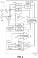
- FIG. 2 shows an LP 102a, 102b.
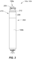
- the LP can include a hermetic housing 202 with electrodes 108a and108b disposed thereon.
- electrode 108a can be separated from but surrounded partially by a fixation mechanism 205, and the electrode 108b can be disposed on the housing 202.
- the fixation mechanism 205 can be a fixation helix, a plurality of hooks, barbs, or other attaching features configured to attach the pacemaker to tissue, such as heart tissue.
- the electrodes 108a and 108b are examples of the electrodes 108 shown in and discussed above with reference to FIG. 2 .
- the housing can also include an electronics compartment 210 within the housing that contains the electronic components necessary for operation of the pacemaker, including, e.g., a pulse generator, receiver, a battery, and a processor for operation.
- the hermetic housing 202 can be adapted to be implanted on or in a human heart, and can be cylindrically shaped, rectangular, spherical, or any other appropriate shapes, for example.
- the housing can comprise a conductive, biocompatible, inert, and anodically safe material such as titanium, 316L stainless steel, or other similar materials.
- the housing can further comprise an insulator disposed on the conductive material to separate electrodes 108a and 108b.
- the insulator can be an insulative coating on a portion of the housing between the electrodes, and can comprise materials such as silicone, polyurethane, parylene, or another biocompatible electrical insulator commonly used for implantable medical devices.
- a single insulator 208 is disposed along the portion of the housing between electrodes 108a and 108b.
- the housing itself can comprise an insulator instead of a conductor, such as an alumina ceramic or other similar materials, and the electrodes can be disposed upon the housing.
- the pacemaker can further include a header assembly 212 to isolate 108a and 108b.
- the header assembly 212 can be made from PEEK, tecothane or another biocompatible plastic, and can contain a ceramic to metal feedthrough, a glass to metal feedthrough, or other appropriate feedthrough insulator as known in the art.
- the electrodes 108a and 108b can comprise pace/sense electrodes, or return electrodes.
- a low-polarization coating can be applied to the electrodes, such as sintered platinum, platinum-iridium, iridium, iridium-oxide, titanium-nitride, carbon, or other materials commonly used to reduce polarization effects, for example.
- electrode 108a can be a pace/sense electrode and electrode 108b can be a return electrode.
- the electrode 108b can be a portion of the conductive housing 202 that does not include an insulator 208.
- a helical fixation mechanism 205 can enable insertion of the device endocardially or epicardially through a guiding catheter.
- a torqueable catheter can be used to rotate the housing and force the fixation device into heart tissue, thus affixing the fixation device (and also the electrode 108a in FIG. 2 ) into contact with stimulable tissue.
- Electrode 108b can serve as an indifferent electrode for sensing and pacing.
- the fixation mechanism may be coated partially or in full for electrical insulation, and a steroid-eluting matrix may be included on or near the device to minimize fibrotic reaction, as is known in conventional pacing electrode-leads.
- LPs 102a and 102b can utilize implant-to-implant (i2i) communication through event messages to coordinate operation with one another in various manners.
- i2i communication, i2i event messages, and i2i event markers are used interchangeably herein to refer to event related messages and IMD/IMD operation related messages transmitted from an implanted device and directed to another implanted device (although external devices, e.g., a programmer, may also receive i2i event messages).
- LP 102a and LP 102b operate as two independent leadless pacers maintaining beat-to-beat dual-chamber functionality via a "Master/Slave" operational configuration.
- the ventricular LP 102b shall be referred to as "vLP” and the atrial LP 102a shall be referred to as "aLP".
- the LP 102 that is designated as the master device may implement all or most dual-chamber diagnostic and therapy determination algorithms.
- the master device may implement all or most dual-chamber diagnostic and therapy determination algorithms.
- the vLP is a "master” device, while the aLP is a "slave” device.
- the aLP may be designated as the master device, while the vLP may be designated as the slave device.
- the master device orchestrates most or all decision-making and timing determinations (including, for example, rate-response changes).
- methods are provided for coordinating operation between first and second leadless pacemakers (LPs) configured to be implanted entirely within first and second chambers of the heart.
- a method transmits an event marker through conductive communication through electrodes located along a housing of the first LP, the event marker indicative of one of a local paced or sensed event.
- the method detects, over a sensing channel, the event marker at the second LP.
- the method identifies the event marker at the second LP based on a predetermined pattern configured to indicate that an event of interest has occurred in a remote chamber.
- the method initiates a related action in the second LP.
- FIG. 4 is a timing diagram 400 demonstrating one example of an i2i communication for a paced event.
- the i2i communication may be transmitted, for example, from LP 102a to LP 102b.
- an i2i transmission 402 is sent prior to delivery of a pace pulse 404 by the transmitting LP (e.g., LP 102).
- the i2i transmission 402 includes an envelope 406 that may include one or more individual pulses.
- envelope 406 includes a low frequency pulse 408 followed by a high frequency pulse train 410.
- Low frequency pulse 408 lasts for a period T i2iLF
- high frequency pulse train 410 lasts for a period T i2iHF .
- the end of low frequency pulse 408 and the beginning of high frequency pulse train 410 are separated by a gap period, T i2iGap .
- the i2i transmission 402 lasts for a period Ti2iP, and pace pulse 404 lasts for a period Tpace.
- the end of i2i transmission 402 and the beginning of pace pulse 404 are separated by a delay period, TdelayP.
- the delay period may be, for example, between approximately 0.0 and 10.0 milliseconds (ms), particularly between approximately 0.1 ms and 2.0 ms, and more particularly approximately 1.0 ms.
- ms milliseconds
- FIG. 5 is a timing diagram 500 demonstrating one example of an i2i communication for a sensed event.
- the i2i communication may be transmitted, for example, from LP 102a to LP 102b.
- the transmitting LP e.g., LP 102a detects the sensed event when a sensed intrinsic activation 502 crosses a sense threshold 504.
- a predetermined delay period, T delayS after the detection, the transmitting LP transmits an i2i transmission 506 that lasts a predetermined period T i2iS .
- the delay period may be, for example, between approximately 0.0 and 10.0 milliseconds (ms), particularly between approximately 0.1 ms and 2.0 ms, and more particularly approximately 1.0 ms.
- i2i transmission 506 may include an envelope that may include one or more individual pulses.
- the envelope of i2i transmission 506 may include a low frequency pulse followed by a high frequency pulse train.
- the first LP produces an AS/AP event marker to indicate that an atrial sensed (AS) event has occurred or an atrial paced (AP) event has occurred or will occur in the immediate future.
- AS atrial sensed
- AP atrial paced
- the AS and AP event markers may be transmitted following the corresponding AS or AP event.
- the first LP may transmit the AP event marker slightly prior to delivering an atrial pacing pulse.
- the second LP initiates an atrioventricular (AV) interval after receiving an AS or AP event marker from the first LP; and initiates a post atrial ventricular blanking (PAVB) interval after receiving an AP event marker from the first LP.
- AV atrioventricular
- PAVB post atrial ventricular blanking
- communication and synchronization between the aLP and vLP is implemented via conducted communication of markers/commands in the event messages (per i2i communication protocol).
- conducted communication represents event messages transmitted from the sensing/pacing electrodes at frequencies outside the RF or Wi-Fi frequency range.
- the event messages may be conveyed over communication channels operating in the RF or Wi-Fi frequency range.
- the figures and corresponding description below illustrate non-limiting examples of markers that may be transmitted in event messages.
- the figures and corresponding description below also include the description of the markers and examples of results that occur in the LP that receives the event message.
- Table 1 represents exemplary event markers sent from the aLP to the vLP
- Table 2 represents exemplary event markers sent from the vLP to the aLP.
- AS event markers are sent from the aLP each time that an atrial event is sensed outside of the post ventricular atrial blanking (PVAB) interval or some other alternatively-defined atrial blanking period.
- the AP event markers are sent from the aLP each time that the aLP delivers a pacing pulse in the atrium.
- the aLP may restrict transmission of AS markers, whereby the aLP transmits AS event markers when atrial events are sensed both outside of the PVAB interval and outside the post ventricular atrial refractory period (PVARP) or some other alternatively-defined atrial refractory period.
- the aLP may not restrict transmission of AS event markers based on the PVARP, but instead transmit the AS event marker every time an atrial event is sensed.
- the vLP When the aLP transmits an AP event marker (indicating that the aLP delivered or is about to deliver a pace pulse to the atrium), the vLP initiates a PVAB timer and an AV interval timer, provided that a PVARP interval is not active. The vLP may also blank its sense amplifiers to prevent possible crosstalk sensing of the remote pace pulse delivered by the aLP.
- an AP event marker indicating that the aLP delivered or is about to deliver a pace pulse to the atrium
- the vLP initiates a PVAB timer and an AV interval timer, provided that a PVARP interval is not active.
- the vLP may also blank its sense amplifiers to prevent possible crosstalk sensing of the remote pace pulse delivered by the aLP.
- V2A Markers / Commands ( i.e ., from vLP to aLP) Marker Description Result in aLP VS Notification of a sensed event in ventricle • Initiate PVARP VP Notification of a paced event in ventricle • Initiate PVAB • Initiate PVARP AP Command to deliver immediate pace pulse in atrium • Deliver immediate pace pulse to atrium
- the foregoing event markers are examples of a subset of markers that may be used to enable the aLP and vLP to maintain full dual chamber functionality.
- the vLP may perform all dual-chamber algorithms, while the aLP may perform atrial-based hardware-related functions, such as PVAB, implemented locally within the aLP.
- the aLP is effectively treated as a remote 'wireless' atrial pace/sense electrode.
- the vLP may perform most but not all dual-chamber algorithms, while the aLP may perform a subset of diagnostic and therapeutic algorithms.
- vLP and aLP may equally perform diagnostic and therapeutic algorithms.
- decision responsibilities may be partitioned separately to one of the aLP or vLP. In other embodiments, decision responsibilities may involve joint inputs and responsibilities.
- ventricular-based pace and sense functionalities are not dependent on any i2i communication, in order to provide safer therapy.
- the system 100 may automatically revert to safe ventricular-based pace/sense functionalities as the vLP device is running all of the necessary algorithms to independently achieve these functionalities.
- the vLP may revert to a VVI mode as the vLP does not depend on i2i communication to perform ventricular pace/sense activities. Once i2i communication is restored, the system 100 can automatically resume dual-chamber functionalities.
- i2i messages Messages that are transmitted between LPs (e.g., the aLP and the vLP) can be referred to herein generally as i2i messages, since they are implant-to-implant messages.
- such messages can include event markers that enable one LP to inform the other LP of a paced event or a sensed event.
- the aLP whenever the aLP senses an atrial event or paces the right atrium, the aLP will transmit an i2i message to the vLP to inform the vLP of the sensed or paced event in the atrium.
- the vLP may start one or more timers that enable the vLP to sense or pace in the right ventricle.
- the vLP may transmit an i2i message to the aLP whenever the vLP senses a ventricular event or paces the right ventricle.
- the LP receiving an i2i message determines based on the extension indicator bits that the received i2i message is not an extended i2i message, then the LP receiving the i2i message can ignore any bits that follow the extension bits. In such a case, the LP receiving the i2i message only decodes the event marker.
- the LP receiving an i2i message determines based on the extension indicator bits that the received i2i message is an extended i2i message, then the LP receiving the i2i message will also decode the bits that follow the extension bits, and determine based on a CRC code (or other type of error detection and correction code), whether or not the i2i message is a valid message.
- the pacing rate indicator can be beat-to-beat interval value (e.g., 0.75 seconds), a code that the aLP can look up and corresponds to a beat-to-beat interval value, or a value that the aLP feeds into an equation to determine the beat-to-beat interval, but is not limited thereto.
- beat-to-beat interval value e.g. 0.75 seconds
- code that the aLP can look up and corresponds to a beat-to-beat interval value e.g. 0.75 seconds
- a code that the aLP can look up and corresponds to a beat-to-beat interval value
- a value that the aLP feeds into an equation to determine the beat-to-beat interval e.g. 0.75 seconds
- Certain embodiments of the present technology described herein provide for an updated i2i communication protocol between LPs, wherein the aLP selectively withholds the transmission of an atrial event message for an atrial event (e.g., an atrial sensed event) when the underlying atrial rate (e.g., intrinsic atrial rate) is relatively consistent/steady across two or more consecutive cardiac cycles, where the criteria that defines "relatively consistent" can be specified by a user (e.g., clinician and/or physician).
- an atrial event e.g., an atrial sensed event
- the underlying atrial rate e.g., intrinsic atrial rate
- the aLP selectively abstains from transmitting atrial event messages to the vLP, and thereby selectively abstains from informing the vLP of certain atrial events, which has the effect of reducing power consumption (associated with the aLP transmitting atrial event messages to the vLP) and thereby increasing the expected longevity of the aLP.
- Dual-chamber pacemaker systems generally enable a clinician to program a specific value for the sensed AV delay (aka the PV delay) that is appropriate for that patient. In reality, however, there may actually be a range of AV delay values that are sufficiently therapeutic for the patient without a clinically meaningful loss of cardiac function. Certain embodiments of the present technology leverage this concept to reduce the frequency with which (i.e., how often) an aLP needs to transmit atrial event messages to a vLP in a dual chamber LP system.
- the aLP detects a series of intrinsic atrial events (labeled A 1 , A 2 , A 3 , etc.) and that the vLP tracks those atrial events (via receipt of associated i2i messages sent by the aLP to the vLP) and paces the right ventricular chamber after defined AV intervals (A 1 V 1 , A 2 V 2 , A 3 V 3 , etc.).
- the vLP can be configured such that the vLP has a backup ventricular-to-ventricular interval timer (VV interval timer) that is used when the vLP fails to receive a valid atrial event message from the aLP during a cardiac cycle.
- VV interval timer ventricular-to-ventricular interval timer
- the AV interval referred to above could be a programmed value of a sensed AV delay (AVD), or it could be a modified interval, such as implemented via a rate-responsive AV delay algorithm, etc. Certain embodiments of the present technology provide an ability to define a range of acceptable AV delay values instead of a singular acceptable value of AV delay.
- This range can be defined as an absolute range (e.g., [AVD min , AVD max ]), as absolute deltas from a target AV delay (e.g., [AVD target - AVD ⁇ , AVD target + AVD ⁇ ], or [AVD target - AVD ⁇ 1 , AVD target + AVD ⁇ 2 ], etc), as a relative percentage from a target AV delay (e.g., [AVD target * (1 - AVD ⁇ % ), AVD target * (1 + AVD ⁇ % )], etc), or any other applicable means to define that range.
- a n A n + 1 interval A n V n interval + V n A n + 1 interval
- V n V n + 1 interval V n A n + 1 interval + A n + 1 V n + 1 interval
- a n + 1 V n + 1 interval A n V n interval .
- Certain embodiments of the present technology described herein take advantage of the realization that a certain amount of variation in the AA interval can be tolerated while enabling a dual chamber LP system to continue to utilize the steady-state VV interval and still maintain a functional AV interval within the defined range of permitted AV delays. Because of the linearity of the relationships above (and from inspection of FIG. 6 ), the AA interval can vary by the same amount of the permitted range of AV delays.
- V n V n + 1 V n A n + 1 + A n + 1 V n + 1
- V n V n + 1 V n A n + 1 + A n V n ⁇ ⁇ AV
- V n V n + 1 V n A n + 1 + A n V n ⁇ ⁇ AV
- V n V n + 1 A n A n + 1 ⁇ ⁇ AV
- a n A n + 1 V n V n + 1 ⁇ ⁇ AV .
- the aLP when a present AA interval matches the immediately preceding AA interval to within ⁇ AV, then the aLP withholds the i2i atrial event message that is usually used to notify the vLP of that atrial sensed event, and instead the vLP relies on the previously initiated VV interval timer to drive the timing of a ventricular paced event that will still provide effective AV tracking to within the defined ⁇ AV tolerance.
- the sensed AV delay (aka the PV delay) is programmed to be 200 msec.
- the aLP could withhold (i.e., abstain from) transmitting an i2i atrial event message to the vLP if the intrinsic atrial interval remains within 1000 ⁇ 50 msec, in which case the subsequent AV interval will still meet the targeted 200 ⁇ 50 msec window.
- certain embodiments of the present technology ensure that each cycle continues to meet this AV tolerance criteria, thereby preventing a net accumulation of deltas across those consecutive cycles from exceeding the originally-defined tolerance window.
- Certain embodiments of the present technology are related to methods, described below with reference to the flow diagrams of FIGS. 7A-7D and 8-10 , which are for use by an implantable dual chamber LP system including an aLP implanted in or on an atrial chamber (e.g., the right atrial chamber, aka the right atrium) and a vLP implanted in or on a ventricular chamber (e.g., the right ventricular chamber, aka the right ventricle).
- an implantable dual chamber LP system including an aLP implanted in or on an atrial chamber (e.g., the right atrial chamber, aka the right atrium) and a vLP implanted in or on a ventricular chamber (e.g., the right ventricular chamber, aka the right ventricle).
- an implantable dual chamber LP system including an aLP implanted in or on an atrial chamber (e.g., the right atrial chamber, aka the right atrium) and a vLP implanted in or
- Certain such embodiments are used by an aLP to selectively abstain from transmitting atrial event messages to a vLP, to thereby conserve power of the aLP, which in turn increases the longevity of the aLP.
- Other embodiments are utilized by a vLP such that the vLP can appropriately pace a ventricle when the vLP does not receive an atrial event message from an aLP because the aLP had purposely abstained from transmitting the atrial event message to conserve its power.
- FIGS. 7A-7D will initially be used to summarize certain methods that are performed by an aLP, such as the aLP 102b described above, but not limited thereto.
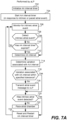
- step 702 involves the aLP initializing its AA interval timer to an initial AA interval value.
- the initial AA interval value can be a base AA interval value that is programmed or set by default.
- the initial AA interval value can be a rate responsive value that depends on an activity level of the patient, which can be determined using a temperature sensor and/or an accelerometer, but not limited thereto.
- the AA interval timer (e.g., 115) can be configured to count-up, or count-down, for the AA interval value once initiated, at which point the sleep timer expires.
- initializing (or resetting) the AA interval timer means setting it to the AA interval value, and expiration of the AA interval timer occurs when the timer reaches zero.
- initializing (or resetting) the AA interval timer means setting it to zero, and expiration of the AA interval timer occurs when the timer reaches the AA interval value.
- Step 704 involves starting the AA interval timer in response to an atrial sensed or paced event. Thereafter, the aLP monitors for an intrinsic atrial event 706, using any known or future developed technique. This can involve, for example, the aLP sensing an EGM using its electrodes (e.g., 108) and sense amplifier (e.g., 132) and monitoring for a P-wave in the EGM, wherein a P-wave corresponds to an intrinsic atrial depolarization (activation), as is known in the art.
- step 708 there is a determination of whether or not an intrinsic atrial event has been detected.
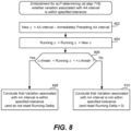
- step 710 determines whether or not the AA interval timer has expired. If the answer to the determination at step 710 is No, then flow returns to step 706, and the aLP continues to monitor for an atrial event. If the answer to the determination at step 708 is Yes, then flow goes to step 712, at which point the AA interval associated with the detected atrial event is determined, wherein the AA interval corresponds to a duration between the atrial event just detected and an immediately preceding atrial event. Similarly, if the answer to the determination at step 710 is Yes, then flow goes to step 712, at which point the AA interval associated with the detected atrial event is determined. As shown in FIG.
- step 714 a variation associated with the AA interval is determined, and then at step 716 there is a determination of whether or not the variation associated with the AA interval is within a specified tolerance. While step 714 and 716 are shown as two separate steps in FIG. 7A , as well as in other flow diagrams, such steps can equivalently be implemented as a single step that involves determining whether or not a variation associated with the AA interval is within a specified tolerance.
- the aLP transmits an atrial event message to the vLP to thereby inform the vLP of the atrial event that was sensed (i.e., of an intrinsic atrial event), or of an atrial paced event that is about to occur (responsive to the AA interval timer expiring before an intrinsic atrial event was detected).
- the atrial event message that the aLP transmits to the vLP at step 718 can include an updated ventricular target interval for the vLP to start using.
- step 720 there is a determination of whether or not an intrinsic atrial event was sensed, and more specifically was detected at step 708. If the answer to step 720 is No, then flow goes to step 722, wherein at step 722 the aLP delivers a pacing pulse to the atrial chamber (in or on which the aLP is implanted). The AA interval timer is then reset (e.g., to the same value to which the AA interval timer was initialized at step 702) and restarted at step 724. If the answer to step 720 is Yes, then there is no need to pace that atrial chamber and flow skips step 722 and goes to step 724.
- step 724 is shown as a single step, it could alternatively be separated into two steps, one what involves resetting the AA interval timer, and another that involves restarting the AA interval timer.
- Such resetting of the AA interval timer can alternatively occur as soon as an intrinsic atrial event is detected (e.g., as part of or following step 708), or as soon the AA interval timer has expired (as determined at step 710), or when the atrial chamber is paced by the aLP.
- Other variations are also possible and within the scope of the embodiments described herein.
- the value of - ⁇ threshold and the value of the + ⁇ threshold can be variable, e.g., can depend in the patient's atrial rate, and more specifically, a most recently determined AA interval. Example details of how the value of - ⁇ threshold and the value of the + ⁇ threshold can be variable were described above, and thus need not be repeated. If the answer to the determination at step 806 is Yes, then flow goes to step 808, and the aLP concludes that the variation associated with the AA interval is within the specified tolerance, and the aLP does not reset the running ⁇ . If the answer to the determination at step 806 is No, then flow goes to step 810, and the aLP concludes that the variation associated with the AA interval is not within the specified tolerance, and the aLP resets the running ⁇ .
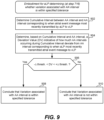
- step 902 involves determining a cumulative interval between the AA interval (most recently determined) and an AA interval corresponding to when the aLP most recently transmitted the atrial event message to the vLP.
- the atrial event occurring immediately preceding when the aLP most recently transmitted the atrial event message to the vLP can be referred to as A -1 .
- the AA interval corresponding to when the aLP most recently transmitted the atrial event message to the vLP can be represented as A -1 A 0
- the AA interval (most recently determined) for the nth atrial event can be represented as A n-1 A n
- the cumulative interval between the AA interval (most recently determined) for the nth atrial event (following when the aLP most recently transmitted the atrial event message to the vLP) and when the aLP most recently transmitted the atrial event message to the vLP can be represented as A 0 A n .
- the aLP determines whether or not the deviation value (DV) is within the specified tolerance, and more specifically determines whether - ⁇ threshold ⁇ DV ⁇ + ⁇ threshold, or alternatively whether - ⁇ threshold ⁇ DV ⁇ + ⁇ threshold.
- the value of - ⁇ threshold and the value of the + ⁇ threshold can be fixed values, e.g., the - ⁇ threshold can be -50 msec and the + ⁇ threshold can be +50 msec.
- the value of - ⁇ threshold and the value of the + ⁇ threshold can be variable, e.g., can depend in the patient's atrial rate, and more specifically, a most recently determined AA interval.
- Example details of how the value of - ⁇ threshold and the value of the + ⁇ threshold can be variable were described above, and thus need not be repeated. If the answer to the determination at step 906 is Yes, then flow goes to step 908, and the aLP concludes that the variation associated with the AA interval is within the specified tolerance. If the answer to the determination at step 906 is No, then flow goes to step 910, and the aLP concludes that the variation associated with the AA interval is not within the specified tolerance.
- an aLP can determine whether or not an AA interval corresponding to an atrial event is within a specified tolerance for the purpose of determining whether or not the aLP should abstain from transmitting an atrial event message to a vLP, with such other ways also being within the scope of the embodiments described herein.
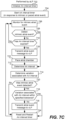
- FIG. 10 will now be used to summarize how a vLP (e.g., 102b) of a dual chamber leadless pacemaker system can utilize its VV interval timer to pace the ventricular chamber (in or on which the vLP is implanted) when the aLP (e.g., 102a) abstains from sending an atrial event message to the vLP.
- FIG. 10 is also used to summarize how the vLP may update its ventricular target interval when appropriate, wherein the ventricular target interval is the starting value used by the VV interval timer of the vLP.
- step 1002 involves the vLP initializing its ventricular target rate to equal a base rate, or a sensor indicated rate, wherein the sensor indicated rate may depend on a patient's activity level as detected, e.g., using a temperature sensor and/or an accelerometer, but not limited thereto.
- Step 1004 involves the vLP starting (or restarting) its VV interval timer with a starting value of the ventricular target rate, and canceling the AV interval timer if it had been started.
- the vLP then simultaneously monitors for an intrinsic ventricular event at step 1006 and for an atrial event message from the aLP at step 1016.
- step 1006 and/or step 1016 may not occur during a blanking period that may be initiated by the vLP for various reasons.
- the vLP can monitor for an intrinsic ventricular event at step 1006 using any known or future developed technique. This can involve, for example, the vLP sensing an EGM using its electrodes (e.g., 108) and sense amplifier (e.g., 132) and monitoring for an R-wave in the EGM, wherein an R-wave corresponds to an intrinsic ventricular depolarization (activation), as in known in the art.
- the vLP sensing an EGM using its electrodes (e.g., 108) and sense amplifier (e.g., 132) and monitoring for an R-wave in the EGM, wherein an R-wave corresponds to an intrinsic ventricular depolarization (activation), as in known in the art.
- activation an intrinsic ventricular depolarization
- step 1008 there is a determination of whether or not an intrinsic ventricular event has been detected. If the answer to the determination at step 1008 is No, then flow goes to step 1010 where there is a determination of whether or not the VV interval timer has been cancelled (e.g.,
- step 1010 If the answer to the determination at step 1010 is No, the flow goes to step 1012 and there is a determination of whether or not the VV interval timer has expired. If the answer to the determination at step 1010 is Yes, then flow goes to step 1022, which is discussed below. If the answer to the determination at step 1012 is Yes, then flow goes to step 1024 and the vLP paces the ventricular chamber by delivering one or more pacing stimulation pulses to the ventricular chamber (in or on which the vLP is implanted). Following the vLP pacing the ventricular chamber at step 1024, flow goes to step 1026, which is discussed below.
- step 1008 if there is a determination at step 1008 that the vLP detected an intrinsic atrial event, i.e., if the answer to the determination at step 1008 is Yes, then flow returns to step 1004, at which time the VV interval timer is restarted using a starting value of the most recently determined ventricular target value, and the AV interval timer is canceled if it had been started.
- step 1016 the vLP monitors for an atrial event message from the aLP, as was noted above.
- step 1018 there is a determination of whether or not the vLP has received an atrial event message from the aLP. If the answer to the determination at step 1018 is No, then flow returns to step 1016. If the answer to the determination at step 1018 is Yes, the flow goes to step 1020.
- step 1020 the AV interval timer of the vLP is started, the VV interval timer is canceled, and flow goes to step 1022.
- An AV interval value used by the AV interval timer can be fixed, or alternatively can be rate dependent.
- an equation or lookup table can be used to determine the AV interval value based on a sensed intrinsic heart rate.
- the AV interval value used by the AV interval timer can be the same regardless of whether the atrial event message received by the vLP from the aLP at step 1018 indicates that the atrial event was a sensed atrial event or a paced atrial event.
- AV interval value used by the AV interval timer can be different when the atrial event message received by the vLP from the aLP at step 1018 indicated that the atrial event was a sensed atrial event, compared to when the atrial event message received by the vLP from the aLP at step 1018 indicated that the atrial event was a paced atrial event.
- An example AV interval value that the AV interval timer may be set to is 200 msec, but is not limited thereto.
- at step 1022 there is a determination of whether or not the AV interval timer has expired. If the answer to the determination at step 1022 is No, then flow returns to step 1006.
- step 1024 the vLP paces the ventricular chamber by delivering one or more pacing stimulation pulses to the ventricular chamber (in or on which the vLP is implanted). Following the vLP pacing the ventricular chamber at step 1024, flow goes to step 1026.
- the vLP determines whether or not it has received atrial event messages from the aLP during the two most recent consecutive cardiac cycles. If the answer to the determination at step 1026 is No, then flow returns to step 1004, which was already described above. If the answer to the determination at step 1026 is Yes, then flow goes to step 1028.
- the vLP determines an interval between instances of the atrial event messages received from the aLP during the two most recent consecutive cardiac cycles. In other words, at step 1028 the vLP determines the duration between when the two most recent atrial event messages that were received from the aLP during the two most recent consecutive cardiac cycles.
- the vLP redefines its ventricular target interval as being equal to the interval determined at step 1028, i.e., as being equal to the interval between instances of the atrial event messages received from the aLP during the two most recent consecutive cardiac cycles. Flow then returns to step 1004 and the VV interval timer is restarted using the ventricular target interval redefined at step 1030.
- the ventricular target interval is redefined (aka updated) by the vLP itself at instances of step 1030 (in FIG. 10 ) when an atrial event message has been received by the vLP during the two most recent cardiac cycles. Accordingly, in certain embodiments described above it is the responsibility of the vLP to determine when it is appropriate to redefine (aka update) the ventricular target interval, and it is the responsibility of the vLP to determine the value of the redefined (aka updated) ventricular target interval.
- the aLP sends the ventricular target interval to the vLP at least some of the times when the aLP sends atrial event messages to the vLP.
- the aLP transmits a ventricular target interval (or an equivalent) to the vLP within a portion of the atrial event message (e.g., in a payload, header, or footer of the atrial event message).
- the ventricular target interval included in a portion of the atrial event message (sent from the aLP to the vLP) at an instance of step 718 is equal to the AA interval determined at the most recent instance of step 712.
- the aLP determines at instances of step 716 whether a variation associated with a just determined AA interval is within a specified tolerance.
- the aLP sends an i2i message from aLP to vLP for at least two consecutive cardiac cycles, to thereby enable vLP to determine a redefined (aka updated) ventricular target interval at instances of step 1030 in FIG. 10 .
- FIGS. 7B and 7D are not relevant to the alternative embodiments where it is the aLP's responsibility (rather than the vLP's responsibility) to determine the value of the redefined (aka updated) ventricular target interval.
- the steps performed by the vLP can be simplified. More specifically, steps 1026, 1028 and 1030 in FIG. 10 can be eliminated, and flow can go directly from step 1024 to step 1004 whenever the ventricular chamber is paced at an instance of step 1024 in FIG. 10 .
- the vLP can receive an update to the ventricular target interval within an atrial event message received by the vLP from the aLP, as part of the vLP monitoring for an atrial event message from the aLP at step 1016 in FIG. 10 .
- the vLP can store and thereafter use the update to the ventricular target interval that the vLP received from the aLP.
- Atrial event messages When atrial event messages are sent from the aLP to the vLP, such atrial event messages may or may not include a payload, e.g., depending on whether there is additional information that the aLP wants to send to the vLP (in addition to an indication that an intrinsic atrial event was sensed by the aLP or that a paced atrial event was (or is about to be) caused by the aLP).
- the aLP may include an automatic mode switch (AMS) message in the payload of the atrial event message.
- AMS automatic mode switch
- the aLP can send an update to the ventricular target interval to the vLP within a payload of an atrial event message. It may also be possible for an update to the ventricular target interval to instead be sent from the aLP to the vLP within a header or a footer of an atrial event message. Other variations are also possible and within the scope of the embodiments described herein.
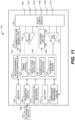
- FIG. 11 shows a block diagram of one embodiment of an IMD (e.g., an LP or ICD) 1101 that is implanted into the patient as part of the implantable cardiac system in accordance with certain embodiments herein.
- the IMD 1101 may provide full-function cardiac resynchronization therapy.
- the IMD 1101 may be implemented with a reduced set of functions and components.
- the IMD may be implemented without ventricular sensing and pacing.
- the IMD 1101 has a housing 1100 to hold the electronic/computing components.
- Housing 1100 (which is often referred to as the "can”, “case”, “encasing”, or “case electrode”) may be programmably selected to act as the return electrode for certain stimulus modes.
- Housing 1100 may further include a connector (not shown) with a plurality of terminals 1102, 1104, 1106, 1108, and 1110. The terminals may be connected to electrodes that are located in various locations on housing 1100 or elsewhere within and about the heart.
- the IMD 1101 includes a programmable microcontroller 1120 that controls various operations of the IMD 1101, including cardiac monitoring and stimulation therapy.
- Microcontroller 1120 includes a microprocessor (or equivalent control circuitry), RAM and/or ROM memory, logic and timing circuitry, state machine circuitry, and I/O circuitry.
- the IMD 1101 further includes a first pulse generator 1122 that generates stimulation pulses for delivery by one or more electrodes coupled thereto.
- Pulse generator 1122 is controlled by microcontroller 1120 via control signal 1124.
- Pulse generator 1122 may be coupled to the select electrode(s) via an electrode configuration switch 1126, which includes multiple switches for connecting the desired electrodes to the appropriate I/O circuits, thereby facilitating electrode programmability.
- Switch 1126 is controlled by a control signal 1128 from microcontroller 1120.
- the IMD may include multiple pulse generators, similar to pulse generator 1122, where each pulse generator is coupled to one or more electrodes and controlled by microcontroller 1120 to deliver select stimulus pulse(s) to the corresponding one or more electrodes.
- Microcontroller 1120 is illustrated as including timing control circuitry 1132 to control the timing of the stimulation pulses (e.g., pacing rate, atrio-ventricular (AV) delay, atrial interconduction (A-A) delay, or ventricular interconduction (V-V) delay, etc.). Timing control circuitry 1132 may also be used for the timing of refractory periods, blanking intervals, noise detection windows, evoked response windows, alert intervals, marker channel timing, and so on. Microcontroller 1120 also has an arrhythmia detector 1134 for detecting arrhythmia conditions and a morphology detector 1136. Although not shown, the microcontroller 1120 may further include other dedicated circuitry and/or firmware/software components that assist in monitoring various conditions of the patient's heart and managing pacing therapies.
- the stimulation pulses e.g., pacing rate, atrio-ventricular (AV) delay, atrial interconduction (A-A) delay, or ventricular interconduction (V-V) delay, etc.
Landscapes
- Health & Medical Sciences (AREA)
- Life Sciences & Earth Sciences (AREA)
- Heart & Thoracic Surgery (AREA)
- Cardiology (AREA)
- Animal Behavior & Ethology (AREA)
- Radiology & Medical Imaging (AREA)
- Nuclear Medicine, Radiotherapy & Molecular Imaging (AREA)
- General Health & Medical Sciences (AREA)
- Public Health (AREA)
- Veterinary Medicine (AREA)
- Biomedical Technology (AREA)
- Engineering & Computer Science (AREA)
- Biophysics (AREA)
- Physiology (AREA)
- Electrotherapy Devices (AREA)
Claims (15)
- Implantierbares System (100), umfassend:einen atrialen kabellosen Herzschrittmacher (aLP) (102a), der dazu konfiguriert ist, in oder an einer Herzvorkammer implantiert zu werden; undeinen ventrikulären kabellosen Herzschrittmacher (vLP) (102), der dazu konfiguriert ist, in oder an eine Herzkammer implantiert zu werden;wobei der aLP (102a) zu Folgendem konfiguriert ist:Bestimmen eines Vorkammer-zu-Vorkammer-Intervalls (AA-Intervalls) für ein Vorkammerereignis, wobei das AA-Intervall eine Dauer zwischen dem Vorkammerereignis und einem unmittelbar folgenden Vorkammerereignis umfasst;dadurch gekennzeichnet, dass der aLP (102a) ferner zu Folgendem konfiguriert ist:Bestimmen, ob eine dem AA-Intervall zugeordnete Variation innerhalb einer spezifizierten Toleranz liegt oder nicht, und basierend darauf Bestimmen, ob eine Vorkammerereignisnachricht an den vLP zum Informieren des vLP über das Vorkammerereignis übertragen werden sollte;Unterlassen des Übertragens der Vorkammerereignisnachricht an den vLP, wenn eine Bestimmung vorliegt, dass die Vorkammerereignisnachricht nicht an den vLP übertragen werden sollte, um somit das Informieren des vLP über das Vorkammerereignis zu unterlassen; undÜbertragen der Vorkammerereignisnachricht an den vLP, wenn eine Bestimmung vorliegt, dass die Vorkammerereignisnachricht an den vLP übertragen werden sollte, um somit den vLP über das Vorkammerereignis zu informieren.
- Implantierbares System (100) nach Anspruch 1, wobei der aLP (102a) zu Folgendem konfiguriert ist:Bestimmen, dass die Vorkammerereignisnachricht nicht an den vLP (102b) übertragen werden sollte, wenn bestimmt wird, dass das AA-Intervall innerhalb der spezifizierten Toleranz liegt; undBestimmen, dass die Vorkammerereignisnachricht an den vLP (102b) übertragen werden sollte, wenn bestimmt wird, dass das AA-Intervall nicht innerhalb der spezifizierten Toleranz liegt.
- Implantierbares System (100) nach Anspruch 1, wobei der aLP (102a) zu Folgendem konfiguriert ist:Bestimmen, dass die Vorkammerereignisnachricht nicht an den vLP (102b) übertragen werden sollte, wenn das AA-Intervall und ein unmittelbar folgendes AA-Intervall jeweils innerhalb der spezifizierten Toleranz liegen; undBestimmen, dass die Vorkammerereignisnachricht an den vLP (102b) übertragen werden sollte, wenn mindestens eines des AA-Intervalls oder des unmittelbar folgenden AA-Intervalls nicht innerhalb der spezifizierten Toleranz liegt.
- Implantierbares System (100) nach einem der Ansprüche 1 bis 3, wobei der aLP (102a) zu Folgendem konfiguriert ist:Bestimmen, ob für intrinsische Vorkammerereignisse, die durch den aLP (102a) erfasst werden, die jeweilige Vorkammerereignisnachricht an den vLP (102b) übertragen werden sollte oder nicht; undBestimmen, dass für Vorkammerschrittmacherereignisse, die durch den aLP (102a) verursacht werden, die jeweilige Vorkammerereignisnachricht an den vLP (102b) übertragen werden sollte.
- Implantierbares System (100) nach einem der Ansprüche 1 bis 3, wobei der aLP (102a) dazu konfiguriert ist, zu bestimmen, ob für intrinsische Vorkammerereignisse, die durch den aLP (102a) erfasst werden, und für Vorkammerschrittmacherereignisse, die durch den aLP (102a) verursacht werden, die jeweilige Vorkammerereignisnachricht an den vLP (102b) übertragen werden sollte oder nicht.
- Implantierbares System (100) nach einem der Ansprüche 1 bis 5, wobei der vLP (102b) zu Folgendem konfiguriert ist:Verwenden eines Zeitgebers (115) für Kammer-zu-Kammer-Intervalle (VV-Intervalle), um zu bestimmen, ob seit einem zuletzt aufgetretenen Kammerereignis ein Kammersollintervall verstrichen ist oder nicht; undEinstellen des VV-Intervallzeitgebers (115) auf das Kammersollintervall, wenn der VV-Intervallzeitgeber (115) zurückgesetzt wird.
- Implantierbares System (100) nach Anspruch 6, wobei der aLP (102a) dazu konfiguriert ist, in die Vorkammerereignisnachricht, die durch den aLP (102a) an den vLP (102b) übertragen wird, eine Aktualisierung des Kammersollintervalls einzubeziehen.
- Implantierbares System (100) nach Anspruch 6 oder 7, wobei der vLP (102b) zu Folgendem konfiguriert ist:Abgeben von Schrittmacherstimulation an die Herzkammer als Reaktion darauf, dass der VV-Intervallzeitgeber (115) abläuft,ohne dass der vLP (102b) während des Kammersollintervalls eine Vorkammerereignisnachricht von dem aLP (102a) empfängt.
- Implantierbares System (100) nach einem der Ansprüche 6 bis 8, wobei der vLP (102b) zu Folgendem konfiguriert ist:Bestimmen, ob während zwei aufeinanderfolgenden zuletzt aufgetretenen Herzzyklen Fälle der Vorkammerereignisnachricht von dem aLP (102a) empfangen wurden; undwenn während zwei aufeinanderfolgenden zuletzt aufgetretenen Herzzyklen Fälle der Vorkammerereignisnachricht von dem aLP (102a) empfangen wurden, Aktualisieren des Kammersollintervalls basierend auf einem Intervall zwischen den Zeitpunkten, zu denen die Fälle der Vorkammerereignisnachricht von dem aLP (102a) während den zwei aufeinanderfolgenden zuletzt aufgetretenen Herzzyklen empfangen wurden.
- Implantierbares System (100) nach einem der Ansprüche 6 bis 9, wobei der vLP (102b) zu Folgendem konfiguriert ist:Verwenden eines Zeitgebers (115) für atrioventrikuläre Intervalle (AV-Intervalle), um zu bestimmen, wann seit einem zuletzt aufgetretenen Vorkammerereignis ein spezifiziertes AV-Intervall verstrichen ist;Starten des AV-Intervallzeitgebers und Abbrechen des VV-Intervallzeitgebers (115) als Reaktion auf Empfangen der Vorkammerereignisnachricht von dem aLP (102a); undAbgeben von Schrittmacherstimulation an die Herzkammer als Reaktion darauf, dass der AV-Intervallzeitgeber (115) abläuft.
- Implantierbares System (100) nach einem der Ansprüche 1 bis 10, wobei der aLP (102a) dazu konfiguriert ist, durch Folgendes zu bestimmen, ob die dem AA-Intervall zugeordnete Variation innerhalb der spezifizierten Toleranz liegt oder nicht:Bestimmen eines laufenden Deltas, das eine kumulative Differenz zwischen jedem aufeinanderfolgenden Paar von AA-Intervallen angibt, die bestimmt wurden, seit die aLP (102a) zuletzt die Vorkammerereignisnachricht an den vLP (102b) übertragen hat; undBestimmen, dass die dem AA-Intervall zugeordnete Variation innerhalb der spezifizierten Toleranz liegt, wenn das laufende Delta innerhalb der spezifizierten Toleranz liegt.
- Implantierbares System (100) nach einem der Ansprüche 1 bis 10, wobei der aLP (102a) dazu konfiguriert ist, durch Folgendes zu bestimmen, ob die dem AA-Intervall zugeordnete Variation innerhalb der spezifizierten Toleranz liegt oder nicht:Bestimmen eines kumulativen Intervalls zwischen dem AA-Intervall und einem AA-Intervall, das dem Zeitpunkt entspricht, zu dem der aLP (102a) zuletzt die Vorkammerereignisnachricht an den vLP (102b) übertragen hat;Bestimmen, basierend auf dem kumulativen Intervall und dem AA-Intervall, eines Abweichungswerts, der angibt, wieviel AA-Intervalle, die während des kumulativen Intervalls auftreten, von dem AA-Intervall, das dem Zeitpunkt entspricht, zu dem der aLP (102a) zuletzt die Vorkammerereignisnachricht an den vLP (102b) übertragen hat, abweichen; undBestimmen, dass die dem AA-Intervall zugeordnete Variation innerhalb der spezifizierten Toleranz liegt, wenn der Abweichungswert innerhalb der spezifizierten Toleranz liegt.
- Implantierbares System (100) nach einem der Ansprüche 1 bis 10, wobei der aLP (102a) dazu konfiguriert ist, durch Folgendes zu bestimmen, ob das AA-Intervall innerhalb der spezifizierten Toleranz liegt oder nicht:Bestimmen eines Deltas zwischen dem AA-Intervall und einem AA-Intervall, das einem unmittelbar folgenden Vorkammerereignis entspricht; undBestimmen, dass die dem AA-Intervall zugeordnete Variation innerhalb der spezifizierten Toleranz liegt, wenn das Delta innerhalb der spezifizierten Toleranz liegt.
- Implantierbares System (100) nach einem der Ansprüche 1 bis 13, wobei der aLP (102a), der das Übertragen der Vorkammerereignisnachricht an den vLP (102b) unterlässt, die Menge an verbrauchter Energie durch den aLP (102a) im Vergleich zu dem aLP (102a), der die Vorkammerereignisnachricht an den vLP (102b) überträgt, reduziert.
- Implantierbares System (100) nach einem der Ansprüche 1 bis 14, wobei der aLP (102a) dazu konfiguriert ist, leitende Kommunikation, Hochfrequenzkommunikation (RF-Kommunikation) oder induktive Kommunikation zu verwenden, um die Vorkammerereignisnachrichten und andere Nachrichtentypen an den vLP zu übertragen.
Applications Claiming Priority (2)
| Application Number | Priority Date | Filing Date | Title |
|---|---|---|---|
| US202363511998P | 2023-07-05 | 2023-07-05 | |
| US18/665,315 US20250010081A1 (en) | 2023-07-05 | 2024-05-15 | Methods, systems and devices for reducing communication burden between leadless pacemakers |
Publications (2)
| Publication Number | Publication Date |
|---|---|
| EP4487902A1 EP4487902A1 (de) | 2025-01-08 |
| EP4487902B1 true EP4487902B1 (de) | 2025-07-02 |
Family
ID=91129529
Family Applications (1)
| Application Number | Title | Priority Date | Filing Date |
|---|---|---|---|
| EP24176398.6A Active EP4487902B1 (de) | 2023-07-05 | 2024-05-16 | Systeme zur reduzierung der kommunikationslast zwischen leitungslosen herzschrittmachern |
Country Status (2)
| Country | Link |
|---|---|
| US (1) | US20250010081A1 (de) |
| EP (1) | EP4487902B1 (de) |
Family Cites Families (5)
| Publication number | Priority date | Publication date | Assignee | Title |
|---|---|---|---|---|
| US9522280B2 (en) * | 2014-11-03 | 2016-12-20 | Pacesetter, Inc. | Leadless dual-chamber pacing system and method |
| US9687654B2 (en) * | 2015-04-23 | 2017-06-27 | Medtronic, Inc. | System and method for dual-chamber pacing |
| US10182765B2 (en) | 2015-09-23 | 2019-01-22 | Pacesetter, Inc. | Systems and methods for classifying signals of interest in a cardiac rhythm management device |
| US10987518B2 (en) * | 2019-01-03 | 2021-04-27 | Pacesetter, Inc. | Terminating pacemaker mediated tachycardia (PMT) in dual chamber leadless pacemaker systems |
| US11931590B2 (en) * | 2020-06-01 | 2024-03-19 | Pacesetter, Inc. | Ventricular far-field sensing to guide atrial leadless pacemaker and beyond |
-
2024
- 2024-05-15 US US18/665,315 patent/US20250010081A1/en active Pending
- 2024-05-16 EP EP24176398.6A patent/EP4487902B1/de active Active
Also Published As
| Publication number | Publication date |
|---|---|
| EP4487902A1 (de) | 2025-01-08 |
| US20250010081A1 (en) | 2025-01-09 |
Similar Documents
| Publication | Publication Date | Title |
|---|---|---|
| EP3630276B1 (de) | Stets eingeschalteter empfänger mit versatzkorrektur für implantat zur implantatkommunikation in einem implantierbaren medizinischen system | |
| US11239928B2 (en) | Dynamic sensitivity and strength control of communication signals between implantable medical devices | |
| US10925490B2 (en) | Mitigating excessive wakeups in leadless dual-chamber pacing systems and other IMD systems | |
| US12151112B2 (en) | Mitigating false messages and effects thereof in multi-chamber leadless pacemaker systems and other IMD systems | |
| EP4091663B1 (de) | Verbesserte implantat-zu-implantat-kommunikation zur verwendung mit implantierbaren medizinischen vorrichtungen | |
| US11766570B2 (en) | Managing communication interference in leadless dual-chamber pacing systems and other IMD systems | |
| EP4487902B1 (de) | Systeme zur reduzierung der kommunikationslast zwischen leitungslosen herzschrittmachern | |
| EP4534138B1 (de) | Zweikammer-herzschrittmachersysteme ohne elektroden | |
| EP4686494A1 (de) | Verbessertes leitfähiges implantat zur implantatkommunikation zur verwendung mit implantierbaren medizinischen vorrichtungen | |
| EP4663236A1 (de) | Verbesserte implantat-implantat-kommunikation zur verwendung mit implantierbaren medizinischen vorrichtungen | |
| US20240350812A1 (en) | Implant to implant communication for use with implantable medical devices | |
| US20260083972A1 (en) | Methods and devices for improved evoked response detection and pacemaker capture management | |
| EP4714491A1 (de) | Vorrichtungen zur verbesserten erkennung von evozierten reaktionen und zur verwaltung der herzschrittmachererfassung | |
| US20250352809A1 (en) | Crosstalk protection for use in multi-chamber leadless pacemaker systems |
Legal Events
| Date | Code | Title | Description |
|---|---|---|---|
| PUAI | Public reference made under article 153(3) epc to a published international application that has entered the european phase |
Free format text: ORIGINAL CODE: 0009012 |
|
| STAA | Information on the status of an ep patent application or granted ep patent |
Free format text: STATUS: THE APPLICATION HAS BEEN PUBLISHED |
|
| AK | Designated contracting states |
Kind code of ref document: A1 Designated state(s): AL AT BE BG CH CY CZ DE DK EE ES FI FR GB GR HR HU IE IS IT LI LT LU LV MC ME MK MT NL NO PL PT RO RS SE SI SK SM TR |
|
| STAA | Information on the status of an ep patent application or granted ep patent |
Free format text: STATUS: REQUEST FOR EXAMINATION WAS MADE |
|
| 17P | Request for examination filed |
Effective date: 20250206 |
|
| GRAP | Despatch of communication of intention to grant a patent |
Free format text: ORIGINAL CODE: EPIDOSNIGR1 |
|
| STAA | Information on the status of an ep patent application or granted ep patent |
Free format text: STATUS: GRANT OF PATENT IS INTENDED |
|
| RIC1 | Information provided on ipc code assigned before grant |
Ipc: A61N 1/372 20060101ALN20250303BHEP Ipc: A61N 1/365 20060101ALN20250303BHEP Ipc: A61B 5/00 20060101ALN20250303BHEP Ipc: A61N 1/375 20060101ALI20250303BHEP Ipc: A61N 1/368 20060101AFI20250303BHEP |
|
| INTG | Intention to grant announced |
Effective date: 20250318 |
|
| GRAS | Grant fee paid |
Free format text: ORIGINAL CODE: EPIDOSNIGR3 |
|
| GRAA | (expected) grant |
Free format text: ORIGINAL CODE: 0009210 |
|
| STAA | Information on the status of an ep patent application or granted ep patent |
Free format text: STATUS: THE PATENT HAS BEEN GRANTED |
|
| AK | Designated contracting states |
Kind code of ref document: B1 Designated state(s): AL AT BE BG CH CY CZ DE DK EE ES FI FR GB GR HR HU IE IS IT LI LT LU LV MC ME MK MT NL NO PL PT RO RS SE SI SK SM TR |
|
| REG | Reference to a national code |
Ref country code: GB Ref legal event code: FG4D |
|
| REG | Reference to a national code |
Ref country code: CH Ref legal event code: EP |
|
| REG | Reference to a national code |
Ref country code: DE Ref legal event code: R096 Ref document number: 602024000268 Country of ref document: DE |
|
| REG | Reference to a national code |
Ref country code: IE Ref legal event code: FG4D |
|
| REG | Reference to a national code |
Ref country code: NL Ref legal event code: MP Effective date: 20250702 |
|
| PG25 | Lapsed in a contracting state [announced via postgrant information from national office to epo] |
Ref country code: PT Free format text: LAPSE BECAUSE OF FAILURE TO SUBMIT A TRANSLATION OF THE DESCRIPTION OR TO PAY THE FEE WITHIN THE PRESCRIBED TIME-LIMIT Effective date: 20251103 |
|
| PG25 | Lapsed in a contracting state [announced via postgrant information from national office to epo] |
Ref country code: NL Free format text: LAPSE BECAUSE OF FAILURE TO SUBMIT A TRANSLATION OF THE DESCRIPTION OR TO PAY THE FEE WITHIN THE PRESCRIBED TIME-LIMIT Effective date: 20250702 |
|
| REG | Reference to a national code |
Ref country code: AT Ref legal event code: MK05 Ref document number: 1808595 Country of ref document: AT Kind code of ref document: T Effective date: 20250702 |
|
| PG25 | Lapsed in a contracting state [announced via postgrant information from national office to epo] |
Ref country code: IS Free format text: LAPSE BECAUSE OF FAILURE TO SUBMIT A TRANSLATION OF THE DESCRIPTION OR TO PAY THE FEE WITHIN THE PRESCRIBED TIME-LIMIT Effective date: 20251102 |
|
| PG25 | Lapsed in a contracting state [announced via postgrant information from national office to epo] |
Ref country code: NO Free format text: LAPSE BECAUSE OF FAILURE TO SUBMIT A TRANSLATION OF THE DESCRIPTION OR TO PAY THE FEE WITHIN THE PRESCRIBED TIME-LIMIT Effective date: 20251002 |
|
| REG | Reference to a national code |
Ref country code: LT Ref legal event code: MG9D |
|
| PG25 | Lapsed in a contracting state [announced via postgrant information from national office to epo] |
Ref country code: AT Free format text: LAPSE BECAUSE OF FAILURE TO SUBMIT A TRANSLATION OF THE DESCRIPTION OR TO PAY THE FEE WITHIN THE PRESCRIBED TIME-LIMIT Effective date: 20250702 |
|
| PG25 | Lapsed in a contracting state [announced via postgrant information from national office to epo] |
Ref country code: FI Free format text: LAPSE BECAUSE OF FAILURE TO SUBMIT A TRANSLATION OF THE DESCRIPTION OR TO PAY THE FEE WITHIN THE PRESCRIBED TIME-LIMIT Effective date: 20250702 |
|
| PG25 | Lapsed in a contracting state [announced via postgrant information from national office to epo] |
Ref country code: HR Free format text: LAPSE BECAUSE OF FAILURE TO SUBMIT A TRANSLATION OF THE DESCRIPTION OR TO PAY THE FEE WITHIN THE PRESCRIBED TIME-LIMIT Effective date: 20250702 |
|
| PG25 | Lapsed in a contracting state [announced via postgrant information from national office to epo] |
Ref country code: GR Free format text: LAPSE BECAUSE OF FAILURE TO SUBMIT A TRANSLATION OF THE DESCRIPTION OR TO PAY THE FEE WITHIN THE PRESCRIBED TIME-LIMIT Effective date: 20251003 |
|
| PG25 | Lapsed in a contracting state [announced via postgrant information from national office to epo] |
Ref country code: CZ Free format text: LAPSE BECAUSE OF FAILURE TO SUBMIT A TRANSLATION OF THE DESCRIPTION OR TO PAY THE FEE WITHIN THE PRESCRIBED TIME-LIMIT Effective date: 20250702 Ref country code: SE Free format text: LAPSE BECAUSE OF FAILURE TO SUBMIT A TRANSLATION OF THE DESCRIPTION OR TO PAY THE FEE WITHIN THE PRESCRIBED TIME-LIMIT Effective date: 20250702 |
|
| PG25 | Lapsed in a contracting state [announced via postgrant information from national office to epo] |
Ref country code: LV Free format text: LAPSE BECAUSE OF FAILURE TO SUBMIT A TRANSLATION OF THE DESCRIPTION OR TO PAY THE FEE WITHIN THE PRESCRIBED TIME-LIMIT Effective date: 20250702 |
|
| PG25 | Lapsed in a contracting state [announced via postgrant information from national office to epo] |
Ref country code: PL Free format text: LAPSE BECAUSE OF FAILURE TO SUBMIT A TRANSLATION OF THE DESCRIPTION OR TO PAY THE FEE WITHIN THE PRESCRIBED TIME-LIMIT Effective date: 20250702 Ref country code: BG Free format text: LAPSE BECAUSE OF FAILURE TO SUBMIT A TRANSLATION OF THE DESCRIPTION OR TO PAY THE FEE WITHIN THE PRESCRIBED TIME-LIMIT Effective date: 20250702 |
|
| PG25 | Lapsed in a contracting state [announced via postgrant information from national office to epo] |
Ref country code: RS Free format text: LAPSE BECAUSE OF FAILURE TO SUBMIT A TRANSLATION OF THE DESCRIPTION OR TO PAY THE FEE WITHIN THE PRESCRIBED TIME-LIMIT Effective date: 20251002 |
|
| PG25 | Lapsed in a contracting state [announced via postgrant information from national office to epo] |
Ref country code: ES Free format text: LAPSE BECAUSE OF FAILURE TO SUBMIT A TRANSLATION OF THE DESCRIPTION OR TO PAY THE FEE WITHIN THE PRESCRIBED TIME-LIMIT Effective date: 20250702 |