EP4487902A1 - Systeme zur reduzierung der kommunikationslast zwischen leitungslosen herzschrittmachern - Google Patents
Systeme zur reduzierung der kommunikationslast zwischen leitungslosen herzschrittmachern Download PDFInfo
- Publication number
- EP4487902A1 EP4487902A1 EP24176398.6A EP24176398A EP4487902A1 EP 4487902 A1 EP4487902 A1 EP 4487902A1 EP 24176398 A EP24176398 A EP 24176398A EP 4487902 A1 EP4487902 A1 EP 4487902A1
- Authority
- EP
- European Patent Office
- Prior art keywords
- interval
- alp
- vlp
- atrial
- atrial event
- Prior art date
- Legal status (The legal status is an assumption and is not a legal conclusion. Google has not performed a legal analysis and makes no representation as to the accuracy of the status listed.)
- Granted
Links
Images

Classifications
-
- A—HUMAN NECESSITIES
- A61—MEDICAL OR VETERINARY SCIENCE; HYGIENE
- A61N—ELECTROTHERAPY; MAGNETOTHERAPY; RADIATION THERAPY; ULTRASOUND THERAPY
- A61N1/00—Electrotherapy; Circuits therefor
- A61N1/18—Applying electric currents by contact electrodes
- A61N1/32—Applying electric currents by contact electrodes alternating or intermittent currents
- A61N1/36—Applying electric currents by contact electrodes alternating or intermittent currents for stimulation
- A61N1/362—Heart stimulators
- A61N1/365—Heart stimulators controlled by a physiological parameter, e.g. heart potential
- A61N1/368—Heart stimulators controlled by a physiological parameter, e.g. heart potential comprising more than one electrode co-operating with different heart regions
- A61N1/3686—Heart stimulators controlled by a physiological parameter, e.g. heart potential comprising more than one electrode co-operating with different heart regions configured for selecting the electrode configuration on a lead
-
- A—HUMAN NECESSITIES
- A61—MEDICAL OR VETERINARY SCIENCE; HYGIENE
- A61N—ELECTROTHERAPY; MAGNETOTHERAPY; RADIATION THERAPY; ULTRASOUND THERAPY
- A61N1/00—Electrotherapy; Circuits therefor
- A61N1/18—Applying electric currents by contact electrodes
- A61N1/32—Applying electric currents by contact electrodes alternating or intermittent currents
- A61N1/36—Applying electric currents by contact electrodes alternating or intermittent currents for stimulation
- A61N1/362—Heart stimulators
- A61N1/365—Heart stimulators controlled by a physiological parameter, e.g. heart potential
- A61N1/368—Heart stimulators controlled by a physiological parameter, e.g. heart potential comprising more than one electrode co-operating with different heart regions
-
- A—HUMAN NECESSITIES
- A61—MEDICAL OR VETERINARY SCIENCE; HYGIENE
- A61N—ELECTROTHERAPY; MAGNETOTHERAPY; RADIATION THERAPY; ULTRASOUND THERAPY
- A61N1/00—Electrotherapy; Circuits therefor
- A61N1/18—Applying electric currents by contact electrodes
- A61N1/32—Applying electric currents by contact electrodes alternating or intermittent currents
- A61N1/36—Applying electric currents by contact electrodes alternating or intermittent currents for stimulation
- A61N1/362—Heart stimulators
- A61N1/37—Monitoring; Protecting
- A61N1/3706—Pacemaker parameters
-
- A—HUMAN NECESSITIES
- A61—MEDICAL OR VETERINARY SCIENCE; HYGIENE
- A61N—ELECTROTHERAPY; MAGNETOTHERAPY; RADIATION THERAPY; ULTRASOUND THERAPY
- A61N1/00—Electrotherapy; Circuits therefor
- A61N1/18—Applying electric currents by contact electrodes
- A61N1/32—Applying electric currents by contact electrodes alternating or intermittent currents
- A61N1/36—Applying electric currents by contact electrodes alternating or intermittent currents for stimulation
- A61N1/372—Arrangements in connection with the implantation of stimulators
- A61N1/375—Constructional arrangements, e.g. casings
- A61N1/3756—Casings with electrodes thereon, e.g. leadless stimulators
-
- A—HUMAN NECESSITIES
- A61—MEDICAL OR VETERINARY SCIENCE; HYGIENE
- A61B—DIAGNOSIS; SURGERY; IDENTIFICATION
- A61B5/00—Measuring for diagnostic purposes; Identification of persons
- A61B5/68—Arrangements of detecting, measuring or recording means, e.g. sensors, in relation to patient
- A61B5/6846—Arrangements of detecting, measuring or recording means, e.g. sensors, in relation to patient specially adapted to be brought in contact with an internal body part, i.e. invasive
- A61B5/6847—Arrangements of detecting, measuring or recording means, e.g. sensors, in relation to patient specially adapted to be brought in contact with an internal body part, i.e. invasive mounted on an invasive device
- A61B5/686—Permanently implanted devices, e.g. pacemakers, other stimulators, biochips
-
- A—HUMAN NECESSITIES
- A61—MEDICAL OR VETERINARY SCIENCE; HYGIENE
- A61N—ELECTROTHERAPY; MAGNETOTHERAPY; RADIATION THERAPY; ULTRASOUND THERAPY
- A61N1/00—Electrotherapy; Circuits therefor
- A61N1/18—Applying electric currents by contact electrodes
- A61N1/32—Applying electric currents by contact electrodes alternating or intermittent currents
- A61N1/36—Applying electric currents by contact electrodes alternating or intermittent currents for stimulation
- A61N1/362—Heart stimulators
- A61N1/365—Heart stimulators controlled by a physiological parameter, e.g. heart potential
- A61N1/36507—Heart stimulators controlled by a physiological parameter, e.g. heart potential controlled by gradient or slope of the heart potential
-
- A—HUMAN NECESSITIES
- A61—MEDICAL OR VETERINARY SCIENCE; HYGIENE
- A61N—ELECTROTHERAPY; MAGNETOTHERAPY; RADIATION THERAPY; ULTRASOUND THERAPY
- A61N1/00—Electrotherapy; Circuits therefor
- A61N1/18—Applying electric currents by contact electrodes
- A61N1/32—Applying electric currents by contact electrodes alternating or intermittent currents
- A61N1/36—Applying electric currents by contact electrodes alternating or intermittent currents for stimulation
- A61N1/372—Arrangements in connection with the implantation of stimulators
- A61N1/37211—Means for communicating with stimulators
- A61N1/37252—Details of algorithms or data aspects of communication system, e.g. handshaking, transmitting specific data or segmenting data
- A61N1/37288—Communication to several implantable medical devices within one patient
Definitions
- Embodiments described herein generally relate to dual chamber leadless pacemaker systems, leadless pacemakers thereof, and methods for use by dual chamber leadless pacemaker systems and leadless pacemakers thereof.
- a dual chamber leadless pacemaker (LP) system can include an atrial leadless pacemaker (aLP) and a ventricular leadless pacemaker (vLP) that utilize implant-to-implant (i2i) communication to coordinate their dual-chamber functionality. More specifically, such a dual chamber LP system may utilize an i2i communication protocol that requires the aLP to transmit an i2i event message to the vLP whenever the aLP senses an intrinsic atrial event or causes a paced atrial event. Similarly, the i2i communication protocol may also require the vLP to transmit an i2i event message to the aLP whenever the vLP senses an intrinsic ventricular event or causes a paced ventricular event.
- the i2i event messages sent between the LPs can be conductive communication messages. That is, conductive communication, which is more energy efficient than radio frequency (RF) communication and inductive communication, may be utilized for the i2i communication. Alternatively, RF or inductive communication may be utilized for the i2i communication that takes place between LPs.
- RF radio frequency
- IMDs implantable medical devices
- LPs implantable medical devices
- the longevity of implantable medical devices (IMDs), such as LPs is dependent on many factors, including the power consumed by such IMDs to perform i2i communication. In certain dual chamber LP systems, the aLP has a smaller battery than the vLP, and the output impedance for the aLP is lower than that for the vLP.
- An implantable system includes an atrial leadless pacemaker (aLP) configured to be implanted in or on an atrial chamber, and a ventricular leadless pacemaker (vLP) configured to be implanted in or on a ventricular chamber.
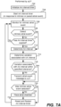
- the aLP is configured to determine an atrial-to-atrial interval (AA interval) for an atrial event, wherein the AA interval comprises a duration between the atrial event and an immediately preceding atrial event. Additionally, the aLP is configured to determine whether or not a variation associated with the AA interval is within a specified tolerance, and based thereon, determine whether or not an atrial event message should be transmitted to the vLP to inform the vLP of the atrial event.
- AA interval atrial-to-atrial interval
- the aLP is configured to determine whether or not a variation associated with the AA interval is within a specified tolerance, and based thereon, determine whether or not an atrial event message should be transmitted to the vLP to inform the vLP of the atrial event.
- the aLP is also configured to abstain from transmitting the atrial event message to the vLP, when there is a determination that the atrial event message should not be transmitted to the vLP, to thereby abstain from informing the vLP of the atrial event. Further, the aLP is configured to transmit the atrial event message to the vLP, when there is a determination that the atrial event message should be transmitted to the vLP, to thereby inform the vLP of the atrial event.
- the aLP is configured to: determine that the atrial event message should not be transmitted to the vLP when the AA interval is determined to be within specified tolerance; and determine that the atrial event message should be transmitted to the vLP when the AA interval is not determined to be within specified tolerance.
- the aLP is configured to: determine that the atrial event message should not be transmitted to the vLP when the AA interval and an immediately preceding AA interval are each within specified tolerance; and determine that the atrial event message should be transmitted to the vLP when at least one of the AA interval or the immediately preceding AA interval is not within specified tolerance.
- the aLP is configured to: determine whether or not a respective atrial event message should be transmitted to the vLP for intrinsic atrial events sensed by the aLP; and determine that a respective atrial event message should be transmitted to the vLP for paced atrial events caused by the aLP.
- the aLP is configured to determine whether or not a respective atrial event message should be transmitted to the vLP for intrinsic atrial events sensed by the aLP and for paced atrial events caused by the aLP.
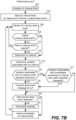
- the vLP is configured to: use a ventricular-to-ventricular interval (W interval) timer to determine whether or not a target ventricular interval has elapsed since a most recent ventricular event has occurred; and deliver pacing stimulation to the ventricular chamber, in response to the W interval timer expiring without the vLP receiving an atrial event message from the aLP during the target ventricular interval.
- W interval ventricular-to-ventricular interval
- the vLP is configured to set the VV interval timer to a ventricular target interval when the VV interval timer is reset. In certain such embodiments, the vLP is configured to determine whether or not instances of the atrial event message were received from the aLP during two consecutive most recent cardiac cycles; and when instances of the atrial event message were received from the aLP during the two consecutive most recent cardiac cycles, update the ventricular target interval based on an interval between when the instances of the atrial event message were received from the aLP during the two consecutive most recent cardiac cycles.
- an update to the ventricular target interval is determined by the aLP and transmitted to the vLP within an atrial event message, which eliminates the need for the vLP to determine whether or not instances of the atrial event message were received from the aLP during two consecutive most recent cardiac cycles, and also eliminates the need for the vLP to determine an interval between when the instances of the atrial event message were received from the aLP during the two consecutive most recent cardiac cycles.
- the vLP is configured to: use an atrioventricular interval (AV interval) timer to determine when a specified AV interval has elapsed since a most recent atrial event has occurred; start the AV interval timer and cancel the VV interval timer in response to receiving an atrial event message from the aLP; and deliver pacing stimulation to the ventricular chamber in response to the AV interval timer expiring.
- AV interval atrioventricular interval
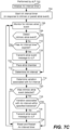
- the aLP is configured to determine whether or not the variation associated with an AA interval is within the specified tolerance by: determining a running delta indicative of a cumulative difference between each consecutive pair of AA intervals determined since the aLP most recently transmitted the atrial event message to the vLP; and determining that the variation associated with the AA interval is within the specified tolerance when the running delta is within the specified tolerance.
- the aLP is configured to determine whether or not the variation associated with an AA interval is within the specified tolerance by: determining a cumulative interval between the AA interval and an AA interval corresponding to when the aLP most recently transmitted the atrial event message to the vLP; determining, based on the cumulative interval and the AA interval, a deviation value indicative of how much AA intervals occurring during the cumulative interval deviate from the AA interval corresponding to when the aLP most recently transmitted the atrial event message to the vLP; and determining that the variation associated with the AA interval is within the specified tolerance when the deviation value is within the specified tolerance.
- the aLP is configured to determine whether or not the variation associated with an AA interval is within the specified tolerance by determining a delta between the AA interval and an AA interval corresponding to an immediately preceding atrial event, and determining that the variation associated with the AA interval is within the specified tolerance when the delta is within the specified tolerance.
- the aLP abstaining from transmitting the atrial event message to the vLP reduces an amount of power consumed by the aLP compared to when the aLP transmits the atrial event message to the vLP.
- the aLP is configured to use conductive communication to transmit the atrial event messages, and other types of messages, to the vLP.
- the aLP is configured to use radio frequency (RF) communication or inductive communication when to transmit the atrial event messages, and other types of messages, to the vLP.
- RF radio frequency
- Certain embodiments of the present technology are directed to methods for use by a dual chamber leadless pacemaker system including an atrial leadless pacemaker (aLP) implanted in or on an atrial chamber and a ventricular leadless pacemaker (vLP) implanted in or on a ventricular chamber.
- aLP atrial leadless pacemaker
- vLP ventricular leadless pacemaker
- Such a method can include the aLP determining an atrial-to-atrial interval (AA interval) for an atrial event and determining whether or not a variation associated with the AA interval is within a specified tolerance, wherein the AA interval comprises a duration between the atrial event and an immediately preceding atrial event.
- AA interval atrial-to-atrial interval
- the method can also include the aLP determining, based on results of the determining whether or not the variation associated with the AA interval is within the specified tolerance, whether or not an atrial event message should be transmitted to the vLP to inform the vLP of the atrial event.
- the method can further include the aLP, in response to determining that the atrial event message should not be transmitted to the vLP, abstaining from transmitting the atrial event message to the vLP and thereby abstaining from informing the vLP of the atrial event.
- the aLP determining whether or not the atrial event message should be transmitted to the vLP comprises the aLP determining that the atrial event message should not be transmitted to the vLP when the AA interval is determined to be within specified tolerance.
- the aLP determining whether or not the atrial event message should be transmitted to the vLP comprises: the aLP determining whether or not a variation associated with an immediately preceding AA interval was within the specified tolerance; the aLP determining that the atrial event message should not be transmitted to the vLP when the AA interval and the immediately preceding AA interval are each within specified tolerance; and the aLP determining that the atrial event message should be transmitted to the vLP when at least one of the AA interval or the immediately preceding AA interval is not within specified tolerance.
- the atrial event and the immediately preceding atrial event each comprise an intrinsic atrial event sensed by the aLP. In accordance with other embodiments, the atrial event and the immediately preceding atrial event each comprise either one of an intrinsic atrial event sensed by the aLP or a paced atrial event caused by the aLP.
- the method also includes the aLP determining a further AA interval when a further atrial event occurs and determining whether or not a variation associated with the further AA interval is within the specified tolerance, wherein the further AA interval corresponds to a duration between the further atrial event and an immediately preceding atrial event.
- the method also includes the aLP, in response to determining that the variation associated with the further AA interval is not within the specified tolerance, transmitting an atrial event message to the vLP and thereby informing the vLP of the further atrial event.
- the vLP uses a ventricular-to-ventricular interval (W interval) timer to determine whether or not a target ventricular interval has elapsed since a most recent ventricular event has occurred.
- the method further comprises the vLP, in response to the W interval timer expiring without the vLP receiving an atrial event message from the aLP during the target ventricular interval, delivering pacing stimulation to the ventricular chamber.
- the vLP sets the W interval timer to a ventricular target interval when the W interval timer is reset.
- the vLP in response to receiving the atrial event message from the aLP, determines whether or not the vLP also received an atrial event message from the aLP during an immediately preceding cardiac cycle and thus received instances of the atrial event message from the aLP during two consecutive most recent cardiac cycles.
- Such a method can also include the vLP, in response to receiving the instances of the atrial event message from the aLP during the two consecutive most recent cardiac cycles, updating the ventricular target interval based on an interval between when the instances of the atrial event message were received from the aLP during the two consecutive most recent cardiac cycles.
- the vLP cancels the W interval timer in response to the vLP receiving the atrial event message from the aLP.
- the atrial event message transmitted by the aLP to the vLP includes an update to the ventricular target interval determined by the aLP.
- the vLP uses an atrioventricular interval (AV interval) timer to determine when a specified AV interval has elapsed since a most recent atrial event has occurred.
- the vLP receives the atrial event message from the aLP, and in response thereto, starts the AV interval timer.
- the vLP delivers pacing stimulation to the ventricular chamber in response to the AV interval timer expiring.
- the aLP determining whether or not the variation associated with the AA interval is within the specified tolerance comprises the aLP: determining a running delta indicative of a cumulative difference between each consecutive pair of AA intervals determined since the aLP most recently transmitted the atrial event message to the vLP; and determining that the variation associated with the AA interval is within the specified tolerance when the running delta is within the specified tolerance.
- the aLP determining whether or not the variation associated with the AA interval is within the specified tolerance comprises the aLP: determining a cumulative interval between the AA interval and an AA interval corresponding to when the aLP most recently transmitted the atrial event message to the vLP; determining, based on the cumulative interval and the AA interval, a deviation value indicative of how much AA intervals occurring during the cumulative interval deviate from the AA interval corresponding to when the aLP most recently transmitted the atrial event message to the vLP; and determining that the variation associated with the AA interval is within the specified tolerance when the deviation value is within the specified tolerance.
- the aLP determining whether or not the variation associated with the AA interval is within the specified tolerance comprises the aLP: determining a delta between the AA interval and an AA interval corresponding to an immediately preceding atrial event; and determining that the variation associated with the AA interval is within the specified tolerance when the delta is within the specified tolerance.
- the aLP abstaining from transmitting the atrial event message to the vLP reduces an amount of power consumed by the aLP compared to when the aLP transmits the atrial event message to the vLP.
- the aLP uses conductive communication when transmitting the atrial event message, and other types of messages, to the vLP.
- the aLP uses radio frequency (RF) communication or inductive communication when transmitting the atrial event message, and other types of messages, to the vLP.
- RF radio frequency
- a method includes an aLP sensing intrinsic atrial events and for each intrinsic atrial event that is sensed determining a respective atrial-to-atrial interval (AA interval) that corresponds to a duration between the intrinsic atrial event and an immediately preceding intrinsic atrial event.
- the method further includes the aLP, based on the determined AA intervals, selectively transmitting and selectively abstaining from transmitting atrial event messages to the vLP.
- AA interval atrial-to-atrial interval
- the aLP determines, for each intrinsic atrial event of at least some of the intrinsic atrial events, whether or not a variation associated with the AA interval corresponding to the intrinsic atrial event is within a specified tolerance, and in dependence thereon the aLP determines whether or not the aLP should transmit an atrial event message to the vLP.
- the aLP abstains from transmitting the atrial event message to the vLP when the AA interval corresponding to an intrinsic atrial event is within the specified tolerance and a further AA interval corresponding to an immediately preceding intrinsic atrial event is also within the specified tolerance.
- Certain embodiments of the present technology are directed to an atrial leadless pacemaker (aLP) configured to be implanted in or on an atrial chamber, wherein the aLP comprises a sense circuit, a transmitter, a pair of electrodes, and a controller.
- the sense circuit is configured to sense a signal indicative of cardiac activity from which atrial events can be detected.
- the pair of electrodes is configured to deliver stimulation pulses to the atrial chamber.
- the controller which is communicatively coupled to the sense circuit and the transmitter, is configured to determine an atrial-to-atrial interval (AA interval) for an atrial event, wherein the AA interval comprises a duration between the atrial event and an immediately preceding atrial event.
- AA interval atrial-to-atrial interval
- the controller is also configured to determine whether or not a variation associated with the AA interval is within a specified tolerance, and based thereon, determine whether or not an atrial event message should be transmitted to the vLP to inform the vLP of the atrial event. Additionally, the controller is configured to cause the transmitter to transmit the atrial event message to the vLP, when there is a determination that the atrial event message should be transmitted to the vLP, to thereby inform the vLP of the atrial event. The controller is further configured to abstain from causing the transmitter to transmit the atrial event message to the vLP, when there is a determination that the atrial event message should not be transmitted to the vLP, to thereby abstain from informing the vLP of the atrial event.
- the aLP includes one or more pulse generators, at least one of which is used to provide pulses to the pair of electrodes to thereby cause the pair of electrodes to deliver stimulation pulses to the atrial chamber under control of the controller.
- the transmitter comprises a conductive communication transmitter including at least one of the one or more pulse generators that provides pulses to the pair of electrodes, under control of the controller, to thereby cause the pair of electrodes to output conductive communication pulses encoded to include the atrial event message.
- the transmitter can comprise one of a radio frequency (RF) communication transmitter or an inductive communication transmitter, and the atrial event message can be transmitted as an RF signal or an inductive signal.
- RF radio frequency
- the sense circuit comprises a sense amplifier coupled to the pair of electrodes, and the signal indicative of cardiac activity comprises an electrogram (EGM) indicative of cardiac electrical activity.
- the sense circuit comprises an accelerometer or a microphone, and the signal indicative of cardiac activity comprises a heart sounds signal.
- the aLP comprises a battery that powers the aLP, and power consumption is reduced when the controller abstains from causing the transmitter to transmit the atrial event message to the vLP, compared to when the controller causes the transmitter to transmit the atrial event message to the vLP.
- Certain embodiments of the present technology are directed to a ventricular leadless pacemaker (vLP) configured to be implanted in or on a ventricular chamber, wherein the vLP comprises a sense circuit, a receiver, a pulse generator, a pair of electrodes, and a controller.
- the sense circuit is configured to sense a signal indicative of cardiac activity from which ventricular events can be detected.
- the pair of electrodes is configured to deliver stimulation pulses output by the pulse generator to the ventricular chamber.
- the controller is communicatively coupled to the sense circuit, the pulse generator, and the receiver.
- An atrioventricular interval (AV interval) timer is used to determine whether a specified AV interval has elapsed since a most recent atrial event
- a ventricular-to-ventricular interval (VV interval) timer is used to determine whether a target ventricular interval has elapsed since a most recent ventricular event.
- At least one of the AV interval timer and the VV interval timer can be implemented by the controller, but that need not be the case.
- the controller of the vLP is configured to start the AV interval timer when an atrial event message is received by the vLP from an atrial leadless pacemaker (aLP) configured to be implanted in or on an atrial chamber.
- aLP atrial leadless pacemaker
- the controller of the vLP is also configured to cause to the pulse generator to provide a stimulation pulse to the pair of electrodes, when the AV interval timer expires, to thereby cause the ventricular chamber to be paced by the vLP at approximately the AV interval following an immediately preceding atrial event.
- the controller of the vLP is configured to set the W interval timer to a ventricular target interval when the W interval timer is reset, start the W interval timer in response to a ventricular event, and cause to the pulse generator to provide a stimulation pulse to the pair of electrodes and cause the W interval timer to be reset, when the W interval timer expires without the receiver receiving the atrial event message from the aLP, to thereby cause the ventricular chamber to be paced at approximately the ventricular target interval following an immediately preceding ventricular event. Additionally, the controller of the vLP is configured to cancel the VV interval timer, when the vLP receives the atrial event message from the aLP.
- the controller of the vLP is also configured to determine whether the atrial event message was also received from the aLP during an immediately preceding cardiac cycle and thus instances of the atrial event message were received from the aLP during two consecutive most recent cardiac cycles. Further, when the instances of the atrial event message were received from the aLP during two consecutive most recent cardiac cycles, the controller of the vLP is configured to update the ventricular target interval based on an interval between when the instances of the atrial event message were received from the aLP during the two consecutive most recent cardiac cycles.
- the atrial event message transmitted by the aLP to the vLP, and received by the vLP includes an update to the ventricular target interval that was determined by the aLP.
- the vLP does not need to determine updates to the ventricular target interval from two consecutive atrial event messages received from aLP.
- the aLP can explicitly inform the vLP of a new value for (i.e., an update to) the ventricular target interval via a single atrial event message.
- the new value for (i.e., an update to) the ventricular target interval, which is determined by the aLP is equal to the AA interval most recently determined by the aLP.
- Certain embodiments of the present technology generally relate to dual chamber leadless pacemaker systems, leadless pacemakers thereof, and methods for use by dual chamber leadless pacemaker systems and leadless pacemakers thereof.
- a dual chamber leadless pacemaker system as described below, include an atrial leadless pacemaker (aLP) implanted in or on an atrial chamber and a ventricular leadless pacemaker (vLP) implanted in or on a ventricular chamber.
- aLP atrial leadless pacemaker
- vLP ventricular leadless pacemaker
- certain embodiments enable the aLP to selectively abstain from transmitting atrial event messages to the vLP, to thereby conserve power used by the aLP and increase it longevity.
- a leadless pacemaker can also be referred to herein as a leadless cardiac pacemaker, or more succinctly as an LP.
- a cardiac pacing system includes a subcutaneous-ICD (S-ICD)
- the S-ICD may perform certain sensing operations and may communicate with one or more LPs by sending and/or receiving messages to and/or from one or more LPs, as can be appreciated from the below discussion.
- the programmer may be used to program one or more IMDs (e.g., LPs), download information to one or more IMDs, and/or upload information from one or more IMDs, as can be appreciated from the below description.
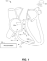
- FIG. 1 illustrates a system 100 that is configured to be implanted in a heart 101.
- the system 100 includes two or more leadless pacemakers (LPs) 102a and 102b located in different chambers of the heart.
- LP 102a is located in a right atrium, while LP 102b is located in a right ventricle.
- LPs 102a and 102b communicate with one another to inform one another of various local physiologic activities, such as local intrinsic events, local paced events and the like.
- LPs 102a and 102b may be constructed in a similar manner, but operate differently based upon which chamber LP 102a or 102b is located.
- the LPs 102a and 102b may sometimes be referred to collectively herein as the LPs 102, or individually as an LP 102.
- LPs 102a and 102b communicate with one another, and/or with an ICD 106, by conductive communication through the same electrodes that are used for sensing and/or delivery of pacing therapy.
- the LPs 102a and 102b may also be able to use conductive communication to communicate with an external device, e.g., a programmer 109, having electrodes placed on the skin of a patient within with the LPs 102a and 102b are implanted.
- the LPs 102a and 102b can potentially include an antenna and/or telemetry coil that would enable them to communicate with one another, the ICD 106 and/or an external device using RF or inductive communication. While only two LPs are shown in FIG. 1 , it is possible that more than two LPs can be implanted in a patient. For example, to provide for bi-ventricular pacing and/or cardiac resynchronization therapy (CRT), in addition to having LPs implanted in the right atrial (RA) chamber and the right ventricular (RV) chamber, a further LP can be implanted in the left ventricular (LV) chamber.
- CTR cardiac resynchronization therapy
- one or more LP 102a can be co-implanted with the ICD 106.
- Each LP 102a uses two or more electrodes located within, on, or within a few centimeters of the housing of the pacemaker, for pacing and sensing at the cardiac chamber, for bidirectional communication with one another, with the programmer 109, and the ICD 106.
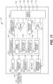
- a block diagram shows an embodiment for portions of the electronics within LPs 102a, 102b configured to provide conductive communication through the sensing/pacing electrode.
- LPs 102a and 102b include at least two leadless electrodes configured for delivering cardiac pacing pulses, sensing evoked and/or natural cardiac electrical signals, and uni-directional or bi-directional communication.
- the two electrodes shown therein are labeled 108a and 108b.
- Such electrodes can be referred to collectively as the electrodes 108, or individually as an electrode 108.
- An LP 102, or other type of IMD can include more than two electrodes 108, depending upon implementation.
- each of the LPs 102a, 102b is shown as including first and second receivers 120 and 122 that collectively define separate first and second communication channels 105 and 107 ( FIG. 1 ), (among other things) between LPs 102a and 102b.
- first and second receivers 120 and 122 are depicted, in other embodiments, each LP 102a, 102b may only include the first receiver 120, or may include additional receivers other than first and second receivers 120 and 122.
- the pulse generator 116 can function as a transmitter that transmits i2i communication signals using the electrodes 108.
- LPs 102a and 102b may communicate over more than just first and second communication channels 105 and 107. In certain embodiments, LPs 102a and 102b may communicate over one common communication channel 105. More specifically, LPs 102a and 102b can communicate conductively over a common physical channel via the same electrodes 108 that are also used to deliver pacing pulses. Usage of the electrodes 108 for communication enables the one or more LPs 102a and 102b to perform antenna-less and telemetry coil-less communication.
- the receivers 120 and 122 can also be referred to, respectively, as a low frequency (LF) receiver 120 and a high frequency (HF) receiver 122, because the receiver 120 is configured to monitor for one or more signals within a relatively low frequency range (e.g., below 100 kHz) and the receiver 122 is configured to monitor for one or more signals within a relatively high frequency range (e.g., above 100 kHz).
- the receiver 120 (and more specifically, at least a portion thereof) is always enabled and monitoring for a wakeup notice, which can simply be a wakeup pulse, within a specific low frequency range (e.g., between 1 kHz and 100 kHz); and the receiver 122 is selectively enabled by the receiver 120.
- the receiver 120 is configured to consume less power than the receiver 122 when both the first and second receivers are enabled. Accordingly, the receiver 120 can also be referred to as a low power receiver 120, and the receiver 122 can also be referred to as a high power receiver 122.
- the low power receiver 120 is incapable of receiving signals within the relatively high frequency range (e.g., above 100 kHz), but consumes significantly less power than the high power receiver 122. This way the low power receiver 120 is capable of always monitoring for a wakeup notice without significantly depleting the battery (e.g., 114) of the LP.
- the high power receiver 122 is selectively enabled by the low power receiver 120, in response to the low power receiver 120 receiving a wakeup notice, so that the high power receiver 122 can receive the higher frequency signals, and thereby handle higher data throughput needed for effective i2i communication without unnecessarily and rapidly depleting the battery of the LP (which the high power receiver 122 may do if it were always enabled).
- the corresponding LP 102a, 102b transmits an implant event message to the other LP 102a, 102b.
- an event message originates from an LP (e.g., 102a) implanted in or on an atrial chamber (e.g., the right atrial chamber)
- the event message can be referred to more specifically as an atrial event message.
- an event message originates from an LP (e.g., LP 102b) implanted in or on a ventricular chamber (e.g., the right ventricular chamber)
- the event message can be referred to more specifically as a ventricular event message.
- an atrial LP 102a senses/paces an atrial event
- the atrial LP 102a transmits an atrial event message including an event marker indicative of a nature of the event (e.g., intrinsic/sensed atrial event, paced atrial event).
- an ventricular LP 102b senses/paces a ventricular event
- the ventricular LP 102b transmits a ventricular event message including an event marker indicative of a nature of the event (e.g., intrinsic/sensed ventricular event, paced ventricular event).
- each LP 102a, 102b transmits a paced event message to the other LP 102a, 102b preceding delivery of an actual pace pulse so that the remote LP can blank its sense inputs in anticipation of that remote pace pulse (to prevent inappropriate crosstalk sensing).
- each LP 102a, 102b transmits a paced event message to the other LP 102a, 102b following delivery of actual pace pulse, and the remote LP relies on an alternative technique for avoiding crosstalk sensing.
- each event message may include a leading trigger pulse (also referred to as an LP wakeup notice, wakeup pulse or wakeup signal) followed by an event marker.
- the notice trigger pulse (also referred to as the wakeup notice, wakeup pulse or wakeup signal) is transmitted over a first channel (e.g., with a pulse duration of approximately 10 ⁇ s to approximately 1ms and/or within a fundamental frequency range of approximately 1kHz to approximately 100kHz).
- the notice trigger pulse indicates that an event marker is about to be transmitted over a second channel (e.g., within a higher frequency range). The event marker can then be transmitted over the second channel.
- the event markers may include data indicative of one or more events (e.g., a sensed intrinsic atrial activation for an atrial located LP, a sensed intrinsic ventricular activation for a ventricular located LP).
- the event markers may include different markers for intrinsic and paced events.
- the event markers may also indicate start or end times for timers (e.g., an AV interval, a blanking interval, etc.).
- the implant event message may include a message segment that includes additional/secondary information.
- the LP (or other IMD) that receives any i2i communication signal from another LP (or other IMD) or from an external device may transmit a receive acknowledgement indicating that the receiving LP (or other IMD) received the i2i communication signal.
- the IMD may transmit a failure-to-receive acknowledgement indicating that the receiving IMD failed to receive the i2i communication signal.
- Other variations are also possible and within the scope of the embodiments described herein.
- the event messages enable the LPs 102a, 102b to deliver synchronized therapy and additional supportive features (e.g., measurements, etc.).
- additional supportive features e.g., measurements, etc.
- each of the LPs 102a and 102b is made aware (through the event messages) when an event occurs in the chamber containing the other LP 102a, 102b.
- Some embodiments described herein provide efficient and reliable processes to maintain synchronization between LPs 102a and 102b without maintaining continuous communication between LPs 102a and 102b.
- low power event messages/signaling may be maintained between LPs 102a and 102b synchronously or asynchronously.
- LPs 102a and 102b may maintain synchronization and regularly communicate at a specific interval. Synchronous event signaling allows the transmitter and receivers in each LP 102a, 102b to use limited (or minimal) power as each LP 102a, 102b is only powered for a small fraction of the time in connection with transmission and reception. For example, LP 102a, 102b may transmit/receive (Tx/Rx) communication messages in time slots having duration of 10-20 ⁇ s, where the Tx/Rx time slots occur periodically (e.g., every 10-20ms).
- Tx/Rx time slots having duration of 10-20 ⁇ s
- LPs 102a and 102b may lose synchronization, even in a synchronous event signaling scheme.
- features may be included in LPs 102a and 102b to maintain device synchronization, and when synchronization is lost, LPs 102a and 102b undergo operations to recover synchronization.
- synchronous event messages/signaling may introduce a delay between transmissions which causes a reaction lag at the receiving LP 102a, 102b. Accordingly, features may be implemented to account for the reaction lag.
- LPs 102a and 102b do not maintain communication synchronization.
- one or more of receivers 120 and 122 of LPs 102a and 102b may be "always on” (always awake) to search for incoming transmissions.
- maintaining LP receivers 120, 122 in an "always on” (always awake) state presents challenges as the received signal level often is low due to high channel attenuation caused by the patient's anatomy. Further, maintaining the receivers awake will deplete the battery 114 more quickly than may be desirable.
- the asynchronous event signaling methods avoid risks associated with losing synchronization between devices.
- the asynchronous event signaling methods utilize additional receiver current between transmissions.
- the channel attenuation may be estimated to have a gain of 1/500 to 1/10000.
- a gain factor may be 1/1000th.
- Transmit current is a design factor in addition to receiver current.
- the system may allocate one-half of the implant communication current budget to the transmitter (e.g., 0.5 ⁇ A for each transmitter).
- a transmitted voltage may be 2.5V.
- the event signal is attenuated as it propagates and would appear at LP 102a, 102b receiver as an amplitude of approximately 0.25mV.
- a pulsed transmission scheme may be utilized in which communication transmissions occur correlated with an event.
- the pulsed transmission scheme may be simplified such that each transmission constitutes a single pulse of a select amplitude and width.
- LPs 102a and 102b may utilize multi-stage receivers that implement a staged receiver wakeup scheme in order to improve reliability yet remain power efficient.
- Each of LPs 102a and 102b may include first and second receivers 120 and 122 that operate with different first and second activation protocols and different first and second receive channels.
- first receiver 120 may be assigned a first activation protocol that is "always on” (also referred to as always awake) and that listens over a first receive channel that has a lower fundamental frequency range/pulse duration (e.g., 1kHz to 100kHz / 10 ⁇ s to approximately 1ms) as compared to the fundamental frequency range (e.g., greater than 100kHz / less than 10 ⁇ s per pulse) assigned to the second receive channel.
- a first activation protocol that is "always on” (also referred to as always awake) and that listens over a first receive channel that has a lower fundamental frequency range/pulse duration (e.g., 1kHz to 100kHz / 10 ⁇ s to approximately 1ms) as compared to the fundamental frequency range (e.g., greater than 100kHz / less than 10 ⁇ s per pulse) assigned to the second receive channel.
- the first receiver 120 may maintain the first channel active (awake) at all times (including when the second channel is inactive (asleep)) in order to listen for messages from a remote LP.
- the second receiver 122 may be assigned a second activation protocol that is a triggered protocol, in which the second receiver 122 becomes active (awake) in response to detection of trigger events over the first receive channel (e.g., when the incoming signal corresponds to the LP wakeup notice, activating the second channel at the local LP).
- the terms active, awake and enabled are used interchangeably herein.
- each LP 102a, 102b is shown as including a controller 112 and a pulse generator 116.
- the controller 112 can include, e.g., a microprocessor (or equivalent control circuitry), RAM and/or ROM memory, logic and timing circuitry, state machine circuitry, and I/O circuitry, but is not limited thereto.
- the controller 112 can further include, e.g., timing control circuitry to control the timing of the stimulation pulses (e.g., pacing rate, atrio-ventricular (AV) delay, atrial interconduction (A-A) delay, or ventricular interconduction (V-V) delay, etc.).
- pacing rate e.g., pacing rate, atrio-ventricular (AV) delay, atrial interconduction (A-A) delay, or ventricular interconduction (V-V) delay, etc.
- AV atrio-ventricular
- A-A atrial interconduction
- V-V ventricular interconduction
- the controller 112 of the LP 102b can be used to implement one or more timers 115, including but not limited to, an AV interval timer and a ventricular-to-ventricular interval (VV interval) timer.
- the controller 112 of the LP 102a can similarly be used to implement one or more timers 115 that may be used by the LP 102a.
- Such timing control circuitry may also be used for the timing of refractory periods, blanking intervals, noise detection windows, evoked response windows, alert intervals, marker channel timing, and so on.
- the controller 112 can further include other dedicated circuitry and/or firmware/software components that assist in monitoring various conditions of the patient's heart and managing pacing therapies.
- the controller 112 and the pulse generator 116 may be configured to transmit event messages, via the electrodes 108, in a manner that does not inadvertently capture the heart in the chamber where LP 102a, 102b is located, such as when the associated chamber is not in a refractory state.
- a LP 102a, 102b that receives an event message may enter an "event refractory" state (or event blanking state) following receipt of the event message.
- the event refractory/blanking state may be set to extend for a determined period of time after receipt of an event message in order to avoid the receiving LP 102a, 102b from inadvertently sensing another signal as an event message that might otherwise cause retriggering.
- the receiving LP 102a, 102b may detect a measurement pulse from another LP 102a, 102b or programmer 109.
- programmer 109 may communicate over a programmer-to-LP channel, with LP 102a, 102b utilizing the same communication scheme.
- the external programmer may listen to the event message transmitted between LP 102a, 102b and synchronize programmer to implant communication such that programmer 109 does not transmit communication signals 113 until after an implant to implant messaging sequence is completed.
- LP 102a, 102b may combine transmit operations with therapy.
- the transmit event marker may be configured to have similar characteristics in amplitude and pulse-width to a pacing pulse and LP 102a, 102b
- a communication capacitor can be provided in LP 102a, 102b.
- the communication capacitor may be used to transmit event signals having higher voltage for the event message pulses to improve communication, such as when the LPs 102a and 102b experience difficulty sensing event messages.
- the high voltage event signaling may be used for implants with high signal attenuation or in the case of a retry for an ARQ (automatic repeat request) handshaking scheme.
- the individual LP 102a can comprise a hermetic housing 110 configured for placement on or attachment to the inside or outside of a cardiac chamber and at least two leadless electrodes 108 proximal to the housing 110 and configured for bidirectional communication with at least one other device 106 within or outside the body.
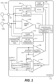
- FIG. 2 depicts a single LP 102a (or 102b) and shows the LP's functional elements substantially enclosed in a hermetic housing 110.
- the LP 102a (or 102b) has at least two electrodes 108 located within, on, or near the housing 110, for delivering pacing pulses to and sensing electrical activity from the muscle of the cardiac chamber, and for bidirectional communication with at least one other device within or outside the body.
- Hermetic feedthroughs 130, 131 conduct electrode signals through the housing 110.
- the housing 110 contains a primary battery 114 to supply power for pacing, sensing, and communication.
- the housing 110 also contains circuits 132 for sensing cardiac activity from the electrodes 108, receivers 120, 122 for receiving information from at least one other device via the electrodes 108, and the pulse generator 116 for generating pacing pulses for delivery via the electrodes 108 and also for transmitting information to at least one other device via the electrodes 108.
- the housing 110 can further contain circuits for monitoring device health, for example a battery current monitor 136 and a battery voltage monitor 138, and can contain circuits for controlling operations in a predetermined manner.
- the electrodes 108 can be configured to communicate bidirectionally among the multiple leadless cardiac pacemakers and/or the implanted ICD 106 to coordinate pacing pulse delivery and optionally other therapeutic or diagnostic features using messages that identify an event at an individual pacemaker originating the message and a pacemaker receiving the message react as directed by the message depending on the origin of the message.
- An LP 102a, 102b that receives the event message reacts as directed by the event message depending on the message origin or location.
- the two or more leadless electrodes 108 can be configured to communicate bidirectionally among the one or more leadless cardiac pacemakers 102a and/or the ICD 106 and transmit data including designated codes for events detected or created by an individual pacemaker. Individual pacemakers can be configured to issue a unique code corresponding to an event type and a location of the sending pacemaker.
- information communicated on the incoming channel can also include an event message from another leadless cardiac pacemaker signifying that the other leadless cardiac pacemaker has sensed a heartbeat or has delivered a pacing pulse, and identifies the location of the other pacemaker.
- LP 102b may receive and relay an event message from LP 102a to the programmer.
- information communicated on the outgoing channel can also include a message to another leadless cardiac pacemaker or pacemakers, or to the ICD, that the sending leadless cardiac pacemaker has sensed a heartbeat or has delivered a pacing pulse at the location of the sending pacemaker.
- the cardiac pacing system 100 may comprise an ICD 106 in addition to one or more LPs 102a, 102b configured for implantation in electrical contact with a cardiac chamber and for performing cardiac rhythm management functions in combination with the implantable ICD 106.
- the implantable ICD 106 and the one or more LPs 102a, 102b configured for leadless intercommunication by information conduction through body tissue and/or wireless transmission between transmitters and receivers in accordance with the discussed herein.
- a cardiac pacing system 100 comprises at least one LP 102a, 102b configured for implantation in electrical contact with a cardiac chamber and configured to perform cardiac pacing functions in combination with the co-implanted ICD 106.
- the leadless cardiac pacemaker or pacemakers 102a comprise at least two leadless electrodes 108 configured for delivering cardiac pacing pulses, sensing evoked and/or natural cardiac electrical signals, and transmitting information to the co-implanted ICD 106.
- a leadless cardiac pacemaker 102a, 102b can comprise two or more leadless electrodes 108 configured for delivering cardiac pacing pulses, sensing evoked and/or natural cardiac electrical signals, and bidirectionally communicating with the co-implanted ICD 106.
- LP 102a, 102b can be configured for operation in a particular location and a particular functionality at manufacture and/or at programming by an external programmer. Bidirectional communication among the multiple leadless cardiac pacemakers can be arranged to communicate notification of a sensed heartbeat or delivered pacing pulse event and encoding type and location of the event to another implanted pacemaker or pacemakers. LP 102a, 102b receiving the communication decode the information and respond depending on location of the receiving pacemaker and predetermined system functionality.
- the LPs 102a and 102b are configured to be implantable in any chamber of the heart, namely either atrium (RA, LA) or either ventricle (RV, LV). Furthermore, for dual-chamber configurations, multiple LPs may be co-implanted (e.g., one in the RA and one in the RV, one in the RV and one in the coronary sinus proximate the LV). Certain pacemaker parameters and functions depend on (or assume) knowledge of the chamber in which the pacemaker is implanted (and thus with which the LP is interacting; e.g., pacing and/or sensing).
- each LP needs to know an identity of the chamber in which the LP is implanted, and processes may be implemented to automatically identify a local chamber associated with each LP.
- the primary battery 114 has positive terminal 140 and negative terminal 142. Current from the positive terminal 140 of primary battery 114 flows through a shunt 144 to a regulator circuit 146 to create a positive voltage supply 148 suitable for powering the remaining circuitry of the pacemaker 102.
- the shunt 144 enables the battery current monitor 136 to provide the controller (e.g., processor) 112 with an indication of battery current drain and indirectly of device health.
- the illustrative power supply can be a primary battery 114.
- the LP is shown as including a temperature sensor 152.
- the temperature sensor can be any one of various different types of well-known temperature sensors, or can be a future developed temperature sensor.
- the temperature sensor 152 can be a thermistor, a thermocouple, a resistance thermometer, or a silicon bandgap temperature sensor, but is not limited thereto. Regardless of how the temperature sensor 152 is implemented, it is preferably that the temperature sensed by the sensor is provided to the controller 112 as a digital signal indicative of the blood temperature of the patient within which the LP is implanted.
- the temperature sensor 152 can be hermetically sealed within the housing 110, but that need not be the case.
- the temperature sensor 152 can be used in various manners.
- the temperature sensor 152 can be used to detect an activity level of the patient to adjust a pacing rate, i.e., for use in rate responsive pacing.
- a pacing rate i.e., for use in rate responsive pacing.
- the controller 112 can be configured to detect an activity level of a patient based on core blood temperature measurements obtained using the temperature sensor 152.
- the LP is also shown as including an accelerometer 154 which can be hermetically contained within the housing 110.
- the accelerometer 154 can be any one of various different types of well-known accelerometers, or can be a future developed accelerometer.
- the accelerometer 154 can be or include, e.g., a MEMS (micro-electromechanical system) multi-axis accelerometer of the type exploiting capacitive or optical cantilever beam techniques, or a piezoelectric accelerometer that employs the piezoelectric effect of certain materials to measure dynamic changes in mechanical variables.
- the accelerometer 154 can be used to detect an activity level of the patient to adjust a pacing rate, i.e., for use in rate responsive pacing.
- a patient's activity level can be monitored based on their heart rate, as detected from an electrogram (EGM) sensed using the electrodes 108, and/or sensed using a plethysmography signal obtained using a plethysmography sensor (not shown) or a heart sound sensor (not shown), but not limited thereto.
- EMM electrogram
- One or more signals produced and output by the accelerometer 154 may be analyzed with respect to frequency content, energy, duration, amplitude and/or other characteristics. Such signals may or may not be amplified and/or filtered prior to being analyzed.
- the signals output by the accelerometer 154 can be analog signals, which can be analyzed in the analog domain, or can be converted to digital signals (by an analog-to-digital converter) and analyzed in the digital domain. Alternatively, the signals output by the accelerometer 154 can already be in the digital domain.
- the one or more signals output by the accelerometer 154 can be analyzed by the controller 112 and/or other circuitry.
- the accelerometer 154 is packaged along with an integrated circuit (IC) that is designed to analyze the signal(s) it generates. In such embodiments, one or more outputs of the packaged sensor/IC can be an indication of acceleration along one or more axes.
- IC integrated circuit
- the accelerometer 154 can be packaged along with an IC that performs signal conditioning (e.g., amplification and/or filtering), performs analog-to-digital conversions, and stores digital data (indicative of the sensor output) in memory (e.g., RAM, which may or may not be within the same package).
- the controller 112 or other circuitry can read the digital data from the memory and analyze the digital data.
- a sensor signal produced by the accelerometer 154 of an LP implanted in or on a cardiac chamber can be used to detect mechanical cardiac activity associated with another cardiac chamber.
- the controller of the LP 102a can detect intrinsic atrial events from an EGM that is sensed by the LP 102a. Alternatively, or additionally, the controller of the LP 102a can detect intrinsic atrial events from one or more signals sensed by the accelerometer 154 thereof and/or from a heart sounds signal sensed by a microphone (not shown) of the LP 102a.
- the controller of the LP 102b can detect intrinsic ventricle events from an EGM that is sensed by the LP 102b. Alternatively, or additionally, the controller of the LP 102b can detect intrinsic ventricular events from one or more signals sensed by the accelerometer 154 thereof and/or from a heart sounds signal sensed by a microphone (not shown) of the LP 102b.
- each of the LPs 102 includes only one of the temperature sensor 152 and the accelerometer 154.
- LP 102a, 102b can manage power consumption to draw limited power from the battery, thereby reducing device volume.
- Each circuit in the system can be designed to avoid large peak currents.
- cardiac pacing can be achieved by discharging a tank capacitor (not shown) across the pacing electrodes. Recharging of the tank capacitor is typically controlled by a charge pump circuit. In a particular embodiment, the charge pump circuit is throttled to recharge the tank capacitor at constant power from the battery.
- the controller 112 in one leadless cardiac pacemaker 102a can access signals on the electrodes 108 and can examine output pulse duration from another pacemaker for usage as a signature for determining triggering information validity and, for a signature arriving within predetermined limits, activating delivery of a pacing pulse following a predetermined delay of zero or more milliseconds.
- the predetermined delay can be preset at manufacture, programmed via an external programmer, or determined by adaptive monitoring to facilitate recognition of the triggering signal and discriminating the triggering signal from noise.
- the controller 112 can examine output pulse waveform from another leadless cardiac pacemaker for usage as a signature for determining triggering information validity and, for a signature arriving within predetermined limits, activating delivery of a pacing pulse following a predetermined delay of zero or more milliseconds.
- the LP 102 can include an RF or inductive transceiver 117 that is coupled to the controller 112, and the RF or inductive transceiver 117 can be coupled to an antenna or inductive coil 118, to thereby enable the LP 102 to utilize RF communication and/or inductive communication to communicate with another LP, another type of IMD, and/or an external device (e.g., 109).
- the communication performed by the LP 102 can be conductive communication, RF communication, or inductive communication, or any combination thereof.
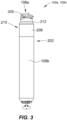
- FIG. 2 shows an LP 102a, 102b.
- the LP can include a hermetic housing 202 with electrodes 108a and108b disposed thereon.
- electrode 108a can be separated from but surrounded partially by a fixation mechanism 205, and the electrode 108b can be disposed on the housing 202.
- the fixation mechanism 205 can be a fixation helix, a plurality of hooks, barbs, or other attaching features configured to attach the pacemaker to tissue, such as heart tissue.
- the electrodes 108a and 108b are examples of the electrodes 108 shown in and discussed above with reference to FIG. 2 .
- the housing can also include an electronics compartment 210 within the housing that contains the electronic components necessary for operation of the pacemaker, including, e.g., a pulse generator, receiver, a battery, and a processor for operation.
- the hermetic housing 202 can be adapted to be implanted on or in a human heart, and can be cylindrically shaped, rectangular, spherical, or any other appropriate shapes, for example.
- the housing can comprise a conductive, biocompatible, inert, and anodically safe material such as titanium, 316L stainless steel, or other similar materials.
- the housing can further comprise an insulator disposed on the conductive material to separate electrodes 108a and 108b.
- the insulator can be an insulative coating on a portion of the housing between the electrodes, and can comprise materials such as silicone, polyurethane, parylene, or another biocompatible electrical insulator commonly used for implantable medical devices.
- a single insulator 208 is disposed along the portion of the housing between electrodes 108a and 108b.
- the housing itself can comprise an insulator instead of a conductor, such as an alumina ceramic or other similar materials, and the electrodes can be disposed upon the housing.
- the pacemaker can further include a header assembly 212 to isolate 108a and 108b.
- the header assembly 212 can be made from PEEK, tecothane or another biocompatible plastic, and can contain a ceramic to metal feedthrough, a glass to metal feedthrough, or other appropriate feedthrough insulator as known in the art.
- the electrodes 108a and 108b can comprise pace/sense electrodes, or return electrodes.
- a low-polarization coating can be applied to the electrodes, such as sintered platinum, platinum-iridium, iridium, iridium-oxide, titanium-nitride, carbon, or other materials commonly used to reduce polarization effects, for example.
- electrode 108a can be a pace/sense electrode and electrode 108b can be a return electrode.
- the electrode 108b can be a portion of the conductive housing 202 that does not include an insulator 208.
- a helical fixation mechanism 205 can enable insertion of the device endocardially or epicardially through a guiding catheter.
- a torqueable catheter can be used to rotate the housing and force the fixation device into heart tissue, thus affixing the fixation device (and also the electrode 108a in FIG. 2 ) into contact with stimulable tissue.
- Electrode 108b can serve as an indifferent electrode for sensing and pacing.
- the fixation mechanism may be coated partially or in full for electrical insulation, and a steroid-eluting matrix may be included on or near the device to minimize fibrotic reaction, as is known in conventional pacing electrode-leads.
- LPs 102a and 102b can utilize implant-to-implant (i2i) communication through event messages to coordinate operation with one another in various manners.
- i2i communication, i2i event messages, and i2i event markers are used interchangeably herein to refer to event related messages and IMD/IMD operation related messages transmitted from an implanted device and directed to another implanted device (although external devices, e.g., a programmer, may also receive i2i event messages).
- LP 102a and LP 102b operate as two independent leadless pacers maintaining beat-to-beat dual-chamber functionality via a "Master/Slave" operational configuration.
- the ventricular LP 102b shall be referred to as "vLP” and the atrial LP 102a shall be referred to as "aLP".
- the LP 102 that is designated as the master device may implement all or most dual-chamber diagnostic and therapy determination algorithms.
- the master device may implement all or most dual-chamber diagnostic and therapy determination algorithms.
- the vLP is a "master” device, while the aLP is a "slave” device.
- the aLP may be designated as the master device, while the vLP may be designated as the slave device.
- the master device orchestrates most or all decision-making and timing determinations (including, for example, rate-response changes).
- methods are provided for coordinating operation between first and second leadless pacemakers (LPs) configured to be implanted entirely within first and second chambers of the heart.
- a method transmits an event marker through conductive communication through electrodes located along a housing of the first LP, the event marker indicative of one of a local paced or sensed event.
- the method detects, over a sensing channel, the event marker at the second LP.
- the method identifies the event marker at the second LP based on a predetermined pattern configured to indicate that an event of interest has occurred in a remote chamber.
- the method initiates a related action in the second LP.
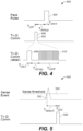
- FIG. 4 is a timing diagram 400 demonstrating one example of an i2i communication for a paced event.
- the i2i communication may be transmitted, for example, from LP 102a to LP 102b.
- an i2i transmission 402 is sent prior to delivery of a pace pulse 404 by the transmitting LP (e.g., LP 102).
- the i2i transmission 402 includes an envelope 406 that may include one or more individual pulses.
- envelope 406 includes a low frequency pulse 408 followed by a high frequency pulse train 410.
- Low frequency pulse 408 lasts for a period T i2iLF
- high frequency pulse train 410 lasts for a period T i2iHF .
- the end of low frequency pulse 408 and the beginning of high frequency pulse train 410 are separated by a gap period, T i2iGap .
- the i2i transmission 402 lasts for a period Ti2iP, and pace pulse 404 lasts for a period Tpace.
- the end of i2i transmission 402 and the beginning of pace pulse 404 are separated by a delay period, TdelayP.
- the delay period may be, for example, between approximately 0.0 and 10.0 milliseconds (ms), particularly between approximately 0.1 ms and 2.0 ms, and more particularly approximately 1.0 ms.
- ms milliseconds
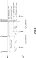
- FIG. 5 is a timing diagram 500 demonstrating one example of an i2i communication for a sensed event.
- the i2i communication may be transmitted, for example, from LP 102a to LP 102b.
- the transmitting LP e.g., LP 102a detects the sensed event when a sensed intrinsic activation 502 crosses a sense threshold 504.
- a predetermined delay period, T delayS after the detection, the transmitting LP transmits an i2i transmission 506 that lasts a predetermined period T i2iS .
- the delay period may be, for example, between approximately 0.0 and 10.0 milliseconds (ms), particularly between approximately 0.1 ms and 2.0 ms, and more particularly approximately 1.0 ms.
- i2i transmission 506 may include an envelope that may include one or more individual pulses.
- the envelope of i2i transmission 506 may include a low frequency pulse followed by a high frequency pulse train.
- the first LP produces an AS/AP event marker to indicate that an atrial sensed (AS) event has occurred or an atrial paced (AP) event has occurred or will occur in the immediate future.
- AS atrial sensed
- AP atrial paced
- the AS and AP event markers may be transmitted following the corresponding AS orAP event.
- the first LP may transmit the AP event marker slightly prior to delivering an atrial pacing pulse.
- the second LP initiates an atrioventricular (AV) interval after receiving an AS or AP event marker from the first LP; and initiates a post atrial ventricular blanking (PAVB) interval after receiving an AP event marker from the first LP.
- AV atrioventricular
- PAVB post atrial ventricular blanking
- communication and synchronization between the aLP and vLP is implemented via conducted communication of markers/commands in the event messages (per i2i communication protocol).
- conducted communication represents event messages transmitted from the sensing/pacing electrodes at frequencies outside the RF or Wi-Fi frequency range.
- the event messages may be conveyed over communication channels operating in the RF or Wi-Fi frequency range.
- the figures and corresponding description below illustrate non-limiting examples of markers that may be transmitted in event messages.
- the figures and corresponding description below also include the description of the markers and examples of results that occur in the LP that receives the event message.
- Table 1 represents exemplary event markers sent from the aLP to the vLP
- Table 2 represents exemplary event markers sent from the vLP to the aLP.
- AS event markers are sent from the aLP each time that an atrial event is sensed outside of the post ventricular atrial blanking (PVAB) interval or some other alternatively-defined atrial blanking period.
- the AP event markers are sent from the aLP each time that the aLP delivers a pacing pulse in the atrium.
- the aLP may restrict transmission of AS markers, whereby the aLP transmits AS event markers when atrial events are sensed both outside of the PVAB interval and outside the post ventricular atrial refractory period (PVARP) or some other alternatively-defined atrial refractory period.
- the aLP may not restrict transmission of AS event markers based on the PVARP, but instead transmit the AS event marker every time an atrial event is sensed.
- Table 1 "A2V" Markers / Commands ( i .
- an aLP when an aLP transmits an event message that includes an AS event marker (indicating that the aLP sensed an intrinsic atrial event), the vLP initiates an AV interval timer. If the aLP transmits an AS event marker for all sensed events, then the vLP would preferably first determine that a PVAB or PVARP interval is not active before initiating an AV interval timer. If however the aLP transmits an AS event marker only when an intrinsic signal is sensed outside of a PVAB or PVARP interval, then the vLP could initiate the AV interval timer upon receiving an AS event marker without first checking the PVAB or PVARP status.
- the vLP When the aLP transmits an AP event marker (indicating that the aLP delivered or is about to deliver a pace pulse to the atrium), the vLP initiates a PVAB timer and an AV interval timer, provided that a PVARP interval is not active. The vLP may also blank its sense amplifiers to prevent possible crosstalk sensing of the remote pace pulse delivered by the aLP.
- an AP event marker indicating that the aLP delivered or is about to deliver a pace pulse to the atrium
- the vLP initiates a PVAB timer and an AV interval timer, provided that a PVARP interval is not active.
- the vLP may also blank its sense amplifiers to prevent possible crosstalk sensing of the remote pace pulse delivered by the aLP.
- V2A Markers / Commands ( i.e ., from vLP to aLP) Marker Description Result in aLP VS Notification of a sensed event in ventricle • Initiate PVARP VP Notification of a paced event in ventricle • Initiate PVAB • Initiate PVARP AP Command to deliver immediate pace pulse in atrium • Deliver immediate pace pulse to atrium
- the vLP when the vLP senses a ventricular event, the vLP transmits an event message including a VS event marker, in response to which the aLP may initiate a PVARP interval timer.
- the vLP delivers or is about to deliver a pace pulse in the ventricle, the vLP transmits VP event marker.
- the aLP receives the VP event marker, the aLP initiates the PVAB interval timer and also the PVARP interval timer.
- the aLP may also blank its sense amplifiers to prevent possible crosstalk sensing of the remote pace pulse delivered by the vLP.
- the vLP may also transmit an event message containing an AP command marker to command the aLP to deliver an immediate pacing pulse in the atrium upon receipt of the command without delay.
- the foregoing event markers are examples of a subset of markers that may be used to enable the aLP and vLP to maintain full dual chamber functionality.
- the vLP may perform all dual-chamber algorithms, while the aLP may perform atrial-based hardware-related functions, such as PVAB, implemented locally within the aLP.
- the aLP is effectively treated as a remote 'wireless' atrial pace/sense electrode.
- the vLP may perform most but not all dual-chamber algorithms, while the aLP may perform a subset of diagnostic and therapeutic algorithms.
- vLP and aLP may equally perform diagnostic and therapeutic algorithms.
- decision responsibilities may be partitioned separately to one of the aLP or vLP. In other embodiments, decision responsibilities may involve joint inputs and responsibilities.
- ventricular-based pace and sense functionalities are not dependent on any i2i communication, in order to provide safer therapy.
- the system 100 may automatically revert to safe ventricular-based pace/sense functionalities as the vLP device is running all of the necessary algorithms to independently achieve these functionalities.
- the vLP may revert to a VVI mode as the vLP does not depend on i2i communication to perform ventricular pace/sense activities. Once i2i communication is restored, the system 100 can automatically resume dual-chamber functionalities.
- i2i messages Messages that are transmitted between LPs (e.g., the aLP and the vLP) can be referred to herein generally as i2i messages, since they are implant-to-implant messages.
- such messages can include event markers that enable one LP to inform the other LP of a paced event or a sensed event.
- the aLP whenever the aLP senses an atrial event or paces the right atrium, the aLP will transmit an i2i message to the vLP to inform the vLP of the sensed or paced event in the atrium.
- the vLP may start one or more timers that enable the vLP to sense or pace in the right ventricle.
- the vLP may transmit an i2i message to the aLP whenever the vLP senses a ventricular event or paces the right ventricle.
- the i2i messages that are sent between LPs may be relatively short messages that simply allow a first LP to inform a second LP of an event that was sensed by the first LP or caused (paced) by the first LP, and vice versa.
- Such i2i messages can be referred to herein as event marker i2i messages, or more succinctly as event i2i messages, or even more succinctly as event messages.
- the i2i messages that are sent between LPs in certain instances, can be extended i2i messages that include (in addition to an event marker) an extension.
- an extended i2i message includes an event marker (e.g., 9 bits), followed by an extension indicator (e.g., 2 bits), followed by an extended message payload portion (e.g., 17 bits), followed by a cyclic redundancy check (CRC) code (e.g., 6 bits) or some other type of error detection and correction code.
- an event marker e.g., 9 bits
- an extension indicator e.g., 2 bits
- an extended message payload portion e.g., 17 bits
- CRC cyclic redundancy check
- the i2i message will include an extension indicator so that the receiving LP knows whether or not the i2i message it receives includes an extension portion. In such embodiments, even a relatively short event i2i message will include an extension indicator.
- the extension indicator e.g., 2 bits
- the extension indicator is used by the LP (or other IMD) sending the i2i message to indicate, to the LP receiving the i2i message, whether or not the i2i message is an extended i2i message.
- the LP receiving an i2i message determines based on the extension indicator bits that the received i2i message is not an extended i2i message, then the LP receiving the i2i message can ignore any bits that follow the extension bits. In such a case, the LP receiving the i2i message only decodes the event marker.
- the LP receiving an i2i message determines based on the extension indicator bits that the received i2i message is an extended i2i message, then the LP receiving the i2i message will also decode the bits that follow the extension bits, and determine based on a CRC code (or other type of error detection and correction code), whether or not the i2i message is a valid message.
- event i2i messages that are not extended i2i messages do not include any error detection and correction code.
- the event marker bits and the extension indicator bits are located, respectively, in an event marker field and an extension indicator field of an i2i message packet.
- the extended portion (that follows the event marker bits and the extension indicator bits) includes message bits (in a message field) and rate indicator bits (in a rate indicator field), which are parts of the payload.
- the payload can alternatively, or additionally, include other types of fields, such as an acknowledgement field that is used in certain situations for one LP to acknowledge reception of an i2i message from another LP of certain (e.g., critical) types of message.
- the payload can include a pacing rate indicator that enables one LP to inform another LP of a pacing rate.
- a pacing rate indicator that enables one LP to inform another LP of a pacing rate.
- an LP system provides rate responsive pacing, wherein a pacing rate is adjusted in dependence on a patient's physical activity as detected, e.g., using an accelerometer, temperature sensor, and/or other type of sensor of an LP.
- the vLP may inform the aLP of the rate at which the patient's heart should be paced so that the aLP and vLP can perform synchronized pacing.
- the vLP can send a pacing rate indicator to the aLP in the payload of an extended i2i message.
- the pacing rate indicator can, e.g., be a value indicating a pacing rate value (e.g., 80 bpm), a code that the aLP that can look up (e.g., in a stored look up table) and corresponds to a pacing rate value, or a value that the aLP feeds into an equation to determine the pacing rate, but is not limited thereto.
- the pacing rate indicator can be beat-to-beat interval value (e.g., 0.75 seconds), a code that the aLP can look up and corresponds to a beat-to-beat interval value, or a value that the aLP feeds into an equation to determine the beat-to-beat interval, but is not limited thereto.
- beat-to-beat interval value e.g. 0.75 seconds
- code that the aLP can look up and corresponds to a beat-to-beat interval value e.g. 0.75 seconds
- a code that the aLP can look up and corresponds to a beat-to-beat interval value
- a value that the aLP feeds into an equation to determine the beat-to-beat interval e.g. 0.75 seconds
- Dual chamber LP systems may utilize i2i communication to provide for synchronous cardiac pacing.
- One possible i2i communication protocol that can be utilized by a dual chamber LP pacemaker system requires that an i2i event message is transmitted from one LP to another LP upon each paced and sensed event associated with the LP.
- an i2i communication protocol may require that an aLP transmits an atrial event message to the vLP each time the aLP detects an atrial sensed event and each time the aLP causes (or is about to cause) an atrial paced event.
- An atrial event message that informs the vLP of an atrial sensed event can be referred to herein more specifically as an atrial sensed event message.
- An atrial event message that informs the vLP of an atrial paced event can be referred to herein more specifically as an atrial paced event message.
- the general use of term atrial event message, as used herein can refer to either an atrial sensed event message or an atrial paced event message.
- an aLP has a smaller battery than a vLP, as may be the case in some dual chamber LP systems, it is even more important to reduce the communication output burden of the aLP. This is also the case because an output impedance for an aLP may be lower than that for a vLP.
- a dual-chamber pacemaker system functions to bridge the dysfunctional AV node by sensing the intrinsic atrial events and then correspondingly pacing the ventricle after an appropriate AV delay.
- an aLP senses each intrinsic atrial event and may transmit an atrial event message to the vLP to notify (aka inform) the vLP of each atrial sensed event.
- the vLP may initiate an AV interval timer and then pace the ventricle when that timer expires.
- the vLP may also transmit a ventricular event message back to the aLP notifying the aLP of the ventricular paced event, or when appropriate, of a ventricular sensed event.
- the aLP may also transmit an atrial event message to the vLP each time the aLP causes (or is about to cause) a paced atrial event, and the vLP may respond accordingly to receiving such a message.
- Certain embodiments of the present technology described herein provide for an updated i2i communication protocol between LPs, wherein the aLP selectively withholds the transmission of an atrial event message for an atrial event (e.g., an atrial sensed event) when the underlying atrial rate (e.g., intrinsic atrial rate) is relatively consistent/steady across two or more consecutive cardiac cycles, where the criteria that defines "relatively consistent" can be specified by a user (e.g., clinician and/or physician).
- an atrial event e.g., an atrial sensed event
- the underlying atrial rate e.g., intrinsic atrial rate
- the aLP selectively abstains from transmitting atrial event messages to the vLP, and thereby selectively abstains from informing the vLP of certain atrial events, which has the effect of reducing power consumption (associated with the aLP transmitting atrial event messages to the vLP) and thereby increasing the expected longevity of the aLP.
- Dual-chamber pacemaker systems generally enable a clinician to program a specific value for the sensed AV delay (aka the PV delay) that is appropriate for that patient. In reality, however, there may actually be a range of AV delay values that are sufficiently therapeutic for the patient without a clinically meaningful loss of cardiac function. Certain embodiments of the present technology leverage this concept to reduce the frequency with which (i.e., how often) an aLP needs to transmit atrial event messages to a vLP in a dual chamber LP system.
- the aLP detects a series of intrinsic atrial events (labeled A 1 , A 2 , A 3 , etc.) and that the vLP tracks those atrial events (via receipt of associated i2i messages sent by the aLP to the vLP) and paces the right ventricular chamber after defined AV intervals (A 1 V 1 , A 2 V 2 , A 3 V 3 , etc.).
- the vLP can be configured such that the vLP has a backup ventricular-to-ventricular interval timer (VV interval timer) that is used when the vLP fails to receive a valid atrial event message from the aLP during a cardiac cycle.
- VV interval timer ventricular-to-ventricular interval timer
- each VA interval is an interval between a paced or intrinsic ventricular event and an immediately succeeding (aka following or subsequent) paced or intrinsic atrial event.
- the AV interval referred to above could be a programmed value of a sensed AV delay (AVD), or it could be a modified interval, such as implemented via a rate-responsive AV delay algorithm, etc. Certain embodiments of the present technology provide an ability to define a range of acceptable AV delay values instead of a singular acceptable value of AV delay.
- This range can be defined as an absolute range (e.g., [AVD min , AVD max ]), as absolute deltas from a target AV delay (e.g., [AVD target - AVD ⁇ , AVD target + AVD ⁇ ], or [AVD target - AVD ⁇ 1 , AVD target + AVD ⁇ 2 ], etc), as a relative percentage from a target AV delay (e.g., [AVD target * (1 - AVD ⁇ % ), AVD target * (1 + AVD ⁇ % )], etc), or any other applicable means to define that range.
- a n A n + 1 interval A n V n interval + V n A n + 1 interval
- V n V n + 1 interval V n A n + 1 interval + A n + 1 V n + 1 interval
- a n + 1 V n + 1 interval A n V n interval .
- Certain embodiments of the present technology described herein take advantage of the realization that a certain amount of variation in the AA interval can be tolerated while enabling a dual chamber LP system to continue to utilize the steady-state W interval and still maintain a functional AV interval within the defined range of permitted AV delays. Because of the linearity of the relationships above (and from inspection of FIG. 6 ), the AA interval can vary by the same amount of the permitted range of AV delays.
- V n V n + 1 V n A n + 1 + A n + 1 V n + 1
- V n V n + 1 V n A n + 1 + A n V n ⁇ ⁇ AV
- V n V n + 1 V n A n + 1 + A n V n ⁇ ⁇ AV
- V n V n + 1 A n A n + 1 ⁇ ⁇ AV
- a n A n + 1 V n V n + 1 ⁇ ⁇ AV .
- the aLP when a present AA interval matches the immediately preceding AA interval to within ⁇ AV, then the aLP withholds the i2i atrial event message that is usually used to notify the vLP of that atrial sensed event, and instead the vLP relies on the previously initiated VV interval timer to drive the timing of a ventricular paced event that will still provide effective AV tracking to within the defined ⁇ AV tolerance.
- the sensed AV delay (aka the PV delay) is programmed to be 200 msec.
- certain embodiments of the present technology ensure that each cycle continues to meet this AV tolerance criteria, thereby preventing a net accumulation of deltas across those consecutive cycles from exceeding the originally-defined tolerance window.
- Certain embodiments of the present technology are related to methods, described below with reference to the flow diagrams of FIGS. 7A-7D and 8-10 , which are for use by an implantable dual chamber LP system including an aLP implanted in or on an atrial chamber (e.g., the right atrial chamber, aka the right atrium) and a vLP implanted in or on a ventricular chamber (e.g., the right ventricular chamber, aka the right ventricle).
- an implantable dual chamber LP system including an aLP implanted in or on an atrial chamber (e.g., the right atrial chamber, aka the right atrium) and a vLP implanted in or on a ventricular chamber (e.g., the right ventricular chamber, aka the right ventricle).
- an implantable dual chamber LP system including an aLP implanted in or on an atrial chamber (e.g., the right atrial chamber, aka the right atrium) and a vLP implanted in or
- Certain such embodiments are used by an aLP to selectively abstain from transmitting atrial event messages to a vLP, to thereby conserve power of the aLP, which in turn increases the longevity of the aLP.
- Other embodiments are utilized by a vLP such that the vLP can appropriately pace a ventricle when the vLP does not receive an atrial event message from an aLP because the aLP had purposely abstained from transmitting the atrial event message to conserve its power.
- FIGS. 7A-7D will initially be used to summarize certain methods that are performed by an aLP, such as the aLP 102b described above, but not limited thereto.
- step 702 involves the aLP initializing its AA interval timer to an initial AA interval value.
- the initial AA interval value can be a base AA interval value that is programmed or set by default.
- the initial AA interval value can be a rate responsive value that depends on an activity level of the patient, which can be determined using a temperature sensor and/or an accelerometer, but not limited thereto.
- the AA interval timer (e.g., 115) can be configured to count-up, or count-down, for the AA interval value once initiated, at which point the sleep timer expires.
- initializing (or resetting) the AA interval timer means setting it to the AA interval value, and expiration of the AA interval timer occurs when the timer reaches zero.
- initializing (or resetting) the AA interval timer means setting it to zero, and expiration of the AA interval timer occurs when the timer reaches the AA interval value.
- Step 704 involves starting the AA interval timer in response to an atrial sensed or paced event. Thereafter, the aLP monitors for an intrinsic atrial event 706, using any known or future developed technique. This can involve, for example, the aLP sensing an EGM using its electrodes (e.g., 108) and sense amplifier (e.g., 132) and monitoring for a P-wave in the EGM, wherein a P-wave corresponds to an intrinsic atrial depolarization (activation), as is known in the art.
- step 708 there is a determination of whether or not an intrinsic atrial event has been detected.
- step 710 determines whether or not the AA interval timer has expired. If the answer to the determination at step 710 is No, then flow returns to step 706, and the aLP continues to monitor for an atrial event. If the answer to the determination at step 708 is Yes, then flow goes to step 712, at which point the AA interval associated with the detected atrial event is determined, wherein the AA interval corresponds to a duration between the atrial event just detected and an immediately preceding atrial event. Similarly, if the answer to the determination at step 710 is Yes, then flow goes to step 712, at which point the AA interval associated with the detected atrial event is determined. As shown in FIG.
- an AA interval may also be determined at an instance of step 712 in response to an intrinsic atrial event being detected, and more specifically, when the answer to the determination at step 708 is Yes. After the AA interval is determined at step 712, flow goes to step 714.
- step 714 a variation associated with the AA interval is determined, and then at step 716 there is a determination of whether or not the variation associated with the AA interval is within a specified tolerance. While step 714 and 716 are shown as two separate steps in FIG. 7A , as well as in other flow diagrams, such steps can equivalently be implemented as a single step that involves determining whether or not a variation associated with the AA interval is within a specified tolerance.
- the aLP transmits an atrial event message to the vLP to thereby inform the vLP of the atrial event that was sensed (i.e., of an intrinsic atrial event), or of an atrial paced event that is about to occur (responsive to the AA interval timer expiring before an intrinsic atrial event was detected).
- the atrial event message that the aLP transmits to the vLP at step 718 can include an updated ventricular target interval for the vLP to start using.
- step 720 there is a determination of whether or not an intrinsic atrial event was sensed, and more specifically was detected at step 708. If the answer to step 720 is No, then flow goes to step 722, wherein at step 722 the aLP delivers a pacing pulse to the atrial chamber (in or on which the aLP is implanted). The AA interval timer is then reset (e.g., to the same value to which the AA interval timer was initialized at step 702) and restarted at step 724. If the answer to step 720 is Yes, then there is no need to pace that atrial chamber and flow skips step 722 and goes to step 724.
- step 724 is shown as a single step, it could alternatively be separated into two steps, one what involves resetting the AA interval timer, and another that involves restarting the AA interval timer.
- Such resetting of the AA interval timer can alternatively occur as soon as an intrinsic atrial event is detected (e.g., as part of or following step 708), or as soon the AA interval timer has expired (as determined at step 710), or when the atrial chamber is paced by the aLP.
- Other variations are also possible and within the scope of the embodiments described herein.
- step 716 if the answer to the determination at step 716 is Yes, i.e., if the AA interval (determined at the most recent instance of step 712) is within the specified tolerance, then flow skips step 718.
- the aLP abstains from transmitting the atrial event message to the vLP (and thereby abstains from informing the vLP of the atrial event) when that AA interval is within the specified tolerance, thereby conserving the aLP's power.
- the vLP when the aLP abstains from transmitting the atrial event message to the vLP (and thereby abstains from informing the vLP of the atrial event), the vLP relies on its W interval timer to know whether and when it should pace the ventricular chamber (in or on which the vLP is implanted). Additional details as to how the aLP can determine whether or not the AA interval is within the specified tolerance are described below, e.g., with reference to FIGS. 8 and 9 .
- the aLP abstains from transmitting an atrial event message to the vLP when the aLP determines that a variation associated with the AA interval (corresponding to an intrinsic atrial event just detected by the aLP, or a paced atrial event about to be caused by the aLP) is within the specified tolerance.
- a variation associated with the AA interval corresponding to an intrinsic atrial event just detected by the aLP, or a paced atrial event about to be caused by the aLP
- the aLP only abstains from transmitting an atrial event message to the vLP when the aLP determines that a variation associated with the AA interval (corresponding to an intrinsic atrial event just detected by the aLP, or a paced atrial event about to be caused by the aLP) is within the specified tolerance, and a variation associated with an immediately preceding AA interval (corresponding to an immediately preceding intrinsic atrial event detected by the aLP, or an immediately preceding paced atrial event caused by the aLP) was also within the specified tolerance.
- a variation associated with the AA interval corresponding to an intrinsic atrial event just detected by the aLP, or a paced atrial event about to be caused by the aLP
- At least two consecutive atrial event messages are transmitted from the aLP to the vLP, following an AA interval (corresponding to an intrinsic atrial event just detected by the aLP, or a paced atrial event about to be caused by the aLP) whose associated variance is not within the specified tolerance.
- AA interval corresponding to an intrinsic atrial event just detected by the aLP, or a paced atrial event about to be caused by the aLP
- a benefit of such embodiments is that they enable the vLP to accurately update (e.g., redefine) its ventricular target interval when appropriate.
- FIG. 7B the steps therein that are the same as in FIG. 7A are labeled the same and need not be described again, because they can be understood from the above description of FIG. 7A .
- a comparison between FIGS. 7B and 7A shows that the only difference between them is the addition of step 717 in FIG. 7B . More specifically, in FIG. 7B , when the answer to the determination at step 716 is Yes (i.e., when the variation associated with the AA interval is within the specified tolerance), flow goes to step 717. At step 717 there is a determination of whether or not the AA interval associated with an immediately preceding atrial event was also within the specified tolerance.
- step 717 If the answer to the determination at step 717 is No, then flow goes to step 718, and the aLP transmit an atrial event message to the vLP, to thereby inform the vLP of an intrinsic atrial event just detected by the aLP (at the most recent instance of step 708), or a paced atrial event about to be caused by the aLP (at an instance of step 722).
- step 718 is skipped and the aLP thereby abstains from transmitting an atrial event message to the vLP, and thereby abstains from informing the vLP of an intrinsic atrial event just detected by the aLP (at the most recent instance of step 708), or a paced atrial event about to be caused by the aLP (at an instance of step 722).
- the aLP thereby abstains from transmitting an atrial event message to the vLP, and thereby abstains from informing the vLP of an intrinsic atrial event just detected by the aLP (at the most recent instance of step 708), or a paced atrial event about to be caused by the aLP (at an instance of step 722).
- the aLP only abstains from transmitting an atrial event message to the vLP when the aLP determines that a variation associated with the AA interval (corresponding to an intrinsic atrial event just detected by the aLP, or a paced atrial event about to be caused by the aLP) is within the specified tolerance, and a variation associated with an immediately preceding AA interval (corresponding to an immediately preceding intrinsic atrial event detected by the aLP, or an immediately preceding paced atrial event caused by the aLP) was also within the specified tolerance.
- the aLP selectively abstains from transmitting an atrial event message to the vLP, based on whether or not the AA interval corresponding to the atrial event is within a specified tolerance, regardless of whether the atrial event (for which the atrial event message is not sent) is an intrinsic atrial event or a paced atrial event.
- the atrial event for which the atrial event message is not sent
- the aLP only selectively abstains from transmitting an atrial event message to the vLP, based on whether or not the AA interval corresponding to the atrial event is within a specified tolerance, where the atrial event (for which the atrial event message is not transmitted) is an intrinsic atrial event.
- the aLP will always transmit an atrial paced event type of atrial event message, regardless of whether or not the AA interval corresponding to the atrial event is within the specified tolerance.
- the aLP only selectively abstains from transmitting atrial event messages to the vLP where the atrial event messages are intended to inform the vLP of atrial sensed events, but not where the atrial event messages are intended to inform the vLP of atrial paced events.
- a benefit of the embodiments summarized below with reference to FIGS. 7C and 7D is that such embodiments enable the vLP to initiate one or more blanking periods, and/or the like, to reduce and preferably prevent any crosstalk detection by the vLP, and more specifically, prevents the vLP from mistakenly detecting and interpreting atrial pacing stimulation as a ventricular sensed event.
- step 718 occurs whenever the answer to the determination at step 710 is Yes (i.e., whenever there is a determination that the AA interval timer has expired), because in the embodiments summarized with reference to FIG. 7C an atrial paced event type of atrial event message is always transmitted from the aLP to the vLP.
- step 718 the aLP paces the atrial chamber at step 722, and the AA interval is determined at step 712. It would also be possible to reverse the order of steps 722 and 712, such that step 712 occurs prior to step 722, since the aLP knows when it is going to pace the atrial chamber. Still referring to FIG. 7C , at step 714 there is a determination of the variation associated with AA interval determined at the most recent instance of step 712. Following step 714 there is a determination at step 720 of whether or not an intrinsic atrial event was detected at step 708.
- step 720 If the answer to the determination at step 720 is No, that means that the atrial event was a paced atrial event for which an atrial event message was already transmitted by the aLP to the vLP at step 718, and flow goes to step 724. If the answer to the determination at step 720 is Yes, then step 716 is performed for the purpose of determining whether or not the aLP should abstain from sending an atrial event message to the vLP and thereby abstain from informing the vLP of the atrial sensed event.
- step 716 there is a determination of whether or not the variation associated with the AA interval is within a specified tolerance. If the answer to the determination at step 716 is No, i.e., if the AA interval is not within the specified tolerance, then flow goes to 718, wherein at step 718 the aLP transmits an atrial event message to the vLP to thereby inform the vLP of the atrial event that was sensed (i.e., of an intrinsic atrial event). If the answer to the determination at step 716 is Yes, i.e., if the AA interval (determined at the most recent instance of step 712) is within the specified tolerance, then flow skips step 718.
- the aLP abstains from transmitting the atrial event message to the vLP (and thereby abstains from informing the vLP of the atrial event) when that AA interval associated with the intrinsic atrial event is within the specified tolerance, thereby conserving the aLP's power.
- the vLP when the aLP abstains from transmitting the atrial event message to the vLP (and thereby abstains from informing the vLP of the atrial event), the vLP relies on its W interval timer to know whether and when it should pace the ventricular chamber (in or on which the vLP is implanted).
- FIGS. 8 and 9 additional details as to how the aLP can determine whether or not the AA interval is within the specified tolerance are described below, e.g., with reference to FIGS. 8 and 9 .
- the aLP abstains from transmitting an atrial event message to the vLP when the aLP determines that a variation associated with the AA interval (corresponding to an intrinsic atrial event just detected by the aLP) is within the specified tolerance.
- a variation associated with the AA interval corresponding to an intrinsic atrial event just detected by the aLP
- the aLP only abstains from transmitting an atrial event message to the vLP when the aLP determines that a variation associated with the AA interval (corresponding to an intrinsic atrial event just detected by the aLP) is within the specified tolerance, and a variation associated with an immediately preceding AA interval (corresponding to an immediately preceding intrinsic atrial event detected by the aLP, or an immediately preceding paced atrial event caused by the aLP) was also within the specified tolerance.
- Such embodiments summarized with reference to FIG. 7D , ensure that at least two consecutive atrial event messages are transmitted from the aLP to the vLP, following an AA interval (corresponding to an intrinsic atrial event just detected by the aLP) whose associated variance is not within the specified tolerance.
- a benefit of such embodiments is that they enable the vLP to accurately update (e.g., redefine) its ventricular target interval when appropriate.
- FIG. 7D the steps therein that are the same as in FIG. 7C are labeled the same and need not be described again, because they can be understood from the above description of FIG. 7C .
- a comparison between FIGS. 7D and 7C shows that the only difference between them is the addition of step 717 in FIG. 7D . More specifically, in FIG. 7D , when the answer to the determination at step 716 is Yes (i.e., when the variation associated with the AA interval is within the specified tolerance), flow goes to step 717. At step 717 there is a determination of whether or not the AA interval associated with an immediately preceding atrial event was also within the specified tolerance.
- step 717 If the answer to the determination at step 717 is No, then flow goes to step 718, and the aLP transmit an atrial event message to the vLP, to thereby inform the vLP of an intrinsic atrial event just detected by the aLP (at the most recent instance of step 708). If the answer to the determination at step 717 is Yes, then step 718 is skipped and the aLP thereby abstains from transmitting an atrial event message to the vLP, and thereby abstains from informing the vLP of an intrinsic atrial event just detected by the aLP (at the most recent instance of step 708). As can be appreciated from FIG.
- the aLP only abstains from transmitting an atrial event message to the vLP when the aLP determines that a variation associated with the AA interval (corresponding to an intrinsic atrial event just detected by the aLP) is within the specified tolerance, and a variation associated with an immediately preceding AA interval (corresponding to an immediately preceding intrinsic atrial event detected by the aLP, or an immediately preceding paced atrial event caused by the aLP was also within the specified tolerance.
- a benefit of the aLP transmitting an atrial paced event type of atrial event message to the vLP prior to the aLP performing atrial pacing is that the atrial event message (transmitted prior to atrial pacing) informs the vLP of the impending pacing stimulation pulse, thereby enabling the vLP to initiate one or more blanking periods, and/or the like, to reduce and preferably prevent any crosstalk detection by the vLP, and more specifically, prevents the vLP from mistakenly detecting and interpreting atrial pacing stimulation as a ventricular sensed event.
- the aLP transmits an atrial paced event type of atrial event message to the vLP just after (e.g., approximately 1 to 5 msec after) the aLP delivers atrial pacing stimulation to the atrial chamber (in or on which the aLP is implanted), in which case the vLP can utilize cross talk mitigation techniques and/or other types of techniques to mitigate the probability of the vLP mistakenly interpreting the atrial pacing stimulation as a ventricular sensed event.
- the vLP may use one or more morphology templates stored in memory of the vLP to determines signal components within a signal sensed by the vLP correspond to an atrial paced event, to prevent the vLP from mistakenly interpreting atrial pacing stimulation as a ventricular sensed event.
- techniques described in commonly assigned U.S. Patent Nos. 10,182,765 and 10,993,674 may be used by the vLP to prevent the vLP from mistakenly interpreting atrial pacing stimulation as a ventricular sensed event.
- Other variations are also possible and within the scope of the embodiments described herein.
- the aLP may pace the atrial chamber as soon as the AA interval timer expires, e.g., immediately following there being a Yes determination at step 710, or at any other time prior to step 718, in which case step 720 can be eliminated.
- step 720 can be eliminated.
- Other variations are also possible, and within the scope of the embodiments described herein.
- the aLP determines, based on results of determining whether or not a variation associated with an AA interval is within a specified tolerance, whether or not an atrial event message should be transmitted to the vLP to inform the vLP of the atrial event. Thereafter, the aLP, in response to determining that the atrial event message should not be transmitted to the vLP, abstains from transmitting the atrial event message to the vLP and thereby abstains from informing the vLP of the atrial event.
- the aLP determines that the atrial event message should be transmitted to the vLP, the aLP transmits the atrial event message to the vLP and thereby informs the vLP of the atrial event.
- the aLP may perform alternative and/or additional steps to determine whether or not a variation associated with an AA interval is within a specified tolerance, and/or to determine whether or not an atrial event message should be transmitted to the vLP to inform the vLP of the atrial event, while being within the scope of the embodiments described herein.
- the aLP can determine a delta (i.e., difference) between the AA interval and an AA interval corresponding to an immediately preceding atrial event, and the aLP can compare the determined delta (i.e., difference) to the specified threshold. The aLP can then determine that the variation associated with the AA interval is within the specified tolerance when the delta is within the specified tolerance, or the aLP can determine that the variation associated with the AA interval is not within the specified tolerance when the determined delta is not within the specified tolerance.
- a delta i.e., difference
- the aLP can determine whether or not the determined delta is within a range specified by a - ⁇ threshold and a + ⁇ threshold, i.e., the aLP can determine whether - ⁇ threshold ⁇ determined delta ⁇ + ⁇ threshold.
- the absolute value of the - ⁇ threshold can be the same as the absolute value of the + ⁇ threshold, but that need not be the case, depending upon the specific implementation.
- the value of - ⁇ threshold and the value of the + ⁇ threshold can be fixed values, e.g., the - ⁇ threshold can be -50 msec and the + ⁇ threshold can be +50 msec.
- the value of - ⁇ threshold and the value of the + ⁇ threshold can be variable, e.g., can depend in the patient's atrial rate, and more specifically, a most recently determined AA interval.
- the - ⁇ threshold can be equal to the product of -0.05 * AA interval
- the + ⁇ threshold can be equal to the product of - 0.05 * AA interval.
- AA interval is 1000 msec
- Other variations are also possible and within the scope of the embodiments described herein.
- a potential detriment of such embodiments is that it is possible that they may not enable the vLP to appropriately adjust its ventricular target interval if AA intervals detected by the aLP slowly drift over a number of consecutive cardiac cycles, which may result in ventricular pacing performed by the vLP not tracking atrial activity as closely as desired.
- the aLP may be configured such that the aLP only abstains from transmitting an atrial event message to the vLP where a net accumulation of deltas across consecutive cardiac cycles remains with the specified tolerance.
- the aLP can determine whether or not a net accumulation of deltas across consecutive cardiac cycles remains with the specified tolerance, some of which are described below with reference to FIGS. 8 and 9 .
- a running ⁇ (initially referred to in step 804) is initialized to zero by the aLP when the aLP starts to operate, or at some other point(s) in time, e.g., at instances of step 810 described below.
- the aLP calculates a new delta (new ⁇ ) as being equal to the AA interval (just determined by the aLP) minus the immediately preceding AA interval (i.e., the AA interval associated with the immediately preceding atrial event).
- the aLP calculates a running delta (running ⁇ ) as being equal to a sum of the most recently calculated (or reset) running ⁇ plus the new ⁇ (just calculated at the most recent instance of step 802).
- the aLP determines whether or not the running ⁇ is within the specified tolerance, and more specifically determines whether - ⁇ threshold ⁇ running delta ⁇ + ⁇ threshold, or alternatively whether - ⁇ threshold ⁇ running delta ⁇ + ⁇ threshold.
- the value of - ⁇ threshold and the value of the + ⁇ threshold can be fixed values, e.g., the - ⁇ threshold can be -50 msec and the + ⁇ threshold can be +50 msec.
- the value of - ⁇ threshold and the value of the + ⁇ threshold can be variable, e.g., can depend in the patient's atrial rate, and more specifically, a most recently determined AA interval. Example details of how the value of - ⁇ threshold and the value of the + ⁇ threshold can be variable were described above, and thus need not be repeated. If the answer to the determination at step 806 is Yes, then flow goes to step 808, and the aLP concludes that the variation associated with the AA interval is within the specified tolerance, and the aLP does not reset the running ⁇ . If the answer to the determination at step 806 is No, then flow goes to step 810, and the aLP concludes that the variation associated with the AA interval is not within the specified tolerance, and the aLP resets the running ⁇ .
- step 902 involves determining a cumulative interval between the AA interval (most recently determined) and an AA interval corresponding to when the aLP most recently transmitted the atrial event message to the vLP.
- the atrial event corresponding to when the aLP most recently transmitted the atrial event message to the vLP can be referred to as A 0
- a first atrial event following when the aLP most recently transmitted the atrial event message to the vLP can be referred to as A 1
- a second atrial event following when the aLP most recently transmitted the atrial event message to the vLP can be referred to as A 2
- ... and more generally that an nth atrial event following when the aLP most recently transmitted the atrial event message to the vLP can be referred to as A n .
- the atrial event occurring immediately preceding when the aLP most recently transmitted the atrial event message to the vLP can be referred to as A -1 .
- the AA interval corresponding to when the aLP most recently transmitted the atrial event message to the vLP can be represented as A -1 A 0
- the AA interval (most recently determined) for the nth atrial event can be represented as A n-1 A n
- the cumulative interval between the AA interval (most recently determined) for the nth atrial event (following when the aLP most recently transmitted the atrial event message to the vLP) and when the aLP most recently transmitted the atrial event message to the vLP can be represented as A 0 A n .
- step 904 involves determining, based on the cumulative interval (i.e., A 0 A n ) and the AA interval (i.e., A n-1 A n ) (most recently determined) for the nth atrial event that occurred since the aLP most recently transmitted the atrial event message to the vLP, a deviation value (DV) indicative of how much AA intervals occurring during the cumulative interval (i.e., during A 0 A n ) deviate from the AA interval (i.e., A -1 A 0 ) corresponding to when the aLP most recently transmitted the atrial event message to the vLP.
- the deviation value (DV) is the variation associated with the AA interval.
- the aLP determines whether or not the deviation value (DV) is within the specified tolerance, and more specifically determines whether - ⁇ threshold ⁇ DV ⁇ + ⁇ threshold, or alternatively whether - ⁇ threshold ⁇ DV ⁇ + ⁇ threshold.
- the value of - ⁇ threshold and the value of the + ⁇ threshold can be fixed values, e.g., the - ⁇ threshold can be -50 msec and the + ⁇ threshold can be +50 msec.
- the value of - ⁇ threshold and the value of the + ⁇ threshold can be variable, e.g., can depend in the patient's atrial rate, and more specifically, a most recently determined AA interval.
- Example details of how the value of - ⁇ threshold and the value of the + ⁇ threshold can be variable were described above, and thus need not be repeated. If the answer to the determination at step 906 is Yes, then flow goes to step 908, and the aLP concludes that the variation associated with the AA interval is within the specified tolerance. If the answer to the determination at step 906 is No, then flow goes to step 910, and the aLP concludes that the variation associated with the AA interval is not within the specified tolerance.
- an aLP can determine whether or not an AA interval corresponding to an atrial event is within a specified tolerance for the purpose of determining whether or not the aLP should abstain from transmitting an atrial event message to a vLP, with such other ways also being within the scope of the embodiments described herein.
- FIG. 10 will now be used to summarize how a vLP (e.g., 102b) of a dual chamber leadless pacemaker system can utilize its W interval timer to pace the ventricular chamber (in or on which the vLP is implanted) when the aLP (e.g., 102a) abstains from sending an atrial event message to the vLP.
- FIG. 10 is also used to summarize how the vLP may update its ventricular target interval when appropriate, wherein the ventricular target interval is the starting value used by the W interval timer of the vLP.
- step 1002 involves the vLP initializing its ventricular target rate to equal a base rate, or a sensor indicated rate, wherein the sensor indicated rate may depend on a patient's activity level as detected, e.g., using a temperature sensor and/or an accelerometer, but not limited thereto.
- Step 1004 involves the vLP starting (or restarting) its W interval timer with a starting value of the ventricular target rate, and canceling the AV interval timer if it had been started. The vLP then simultaneously monitors for an intrinsic ventricular event at step 1006 and for an atrial event message from the aLP at step 1016. In certain embodiments, step 1006 and/or step 1016 may not occur during a blanking period that may be initiated by the vLP for various reasons.
- the vLP can monitor for an intrinsic ventricular event at step 1006 using any known or future developed technique. This can involve, for example, the vLP sensing an EGM using its electrodes (e.g., 108) and sense amplifier (e.g., 132) and monitoring for an R-wave in the EGM, wherein an R-wave corresponds to an intrinsic ventricular depolarization (activation), as in known in the art.
- the vLP sensing an EGM using its electrodes (e.g., 108) and sense amplifier (e.g., 132) and monitoring for an R-wave in the EGM, wherein an R-wave corresponds to an intrinsic ventricular depolarization (activation), as in known in the art.
- activation an intrinsic ventricular depolarization
- step 1008 there is a determination of whether or not an intrinsic ventricular event has been detected. If the answer to the determination at step 1008 is No, then flow goes to step 1010 where there is a determination of whether or not the W interval timer has been cancelled (e.g., at
- step 1010 If the answer to the determination at step 1010 is No, the flow goes to step 1012 and there is a determination of whether or not the W interval timer has expired. If the answer to the determination at step 1010 is Yes, then flow goes to step 1022, which is discussed below. If the answer to the determination at step 1012 is Yes, then flow goes to step 1024 and the vLP paces the ventricular chamber by delivering one or more pacing stimulation pulses to the ventricular chamber (in or on which the vLP is implanted). Following the vLP pacing the ventricular chamber at step 1024, flow goes to step 1026, which is discussed below.
- step 1008 if there is a determination at step 1008 that the vLP detected an intrinsic atrial event, i.e., if the answer to the determination at step 1008 is Yes, then flow returns to step 1004, at which time the VV interval timer is restarted using a starting value of the most recently determined ventricular target value, and the AV interval timer is canceled if it had been started.
- step 1016 the vLP monitors for an atrial event message from the aLP, as was noted above.
- step 1018 there is a determination of whether or not the vLP has received an atrial event message from the aLP. If the answer to the determination at step 1018 is No, then flow returns to step 1016. If the answer to the determination at step 1018 is Yes, the flow goes to step 1020.
- step 1020 the AV interval timer of the vLP is started, the W interval timer is canceled, and flow goes to step 1022.
- An AV interval value used by the AV interval timer can be fixed, or alternatively can be rate dependent.
- an equation or lookup table can be used to determine the AV interval value based on a sensed intrinsic heart rate.
- the AV interval value used by the AV interval timer can be the same regardless of whether the atrial event message received by the vLP from the aLP at step 1018 indicates that the atrial event was a sensed atrial event or a paced atrial event.
- AV interval value used by the AV interval timer can be different when the atrial event message received by the vLP from the aLP at step 1018 indicated that the atrial event was a sensed atrial event, compared to when the atrial event message received by the vLP from the aLP at step 1018 indicated that the atrial event was a paced atrial event.
- An example AV interval value that the AV interval timer may be set to is 200 msec, but is not limited thereto.
- at step 1022 there is a determination of whether or not the AV interval timer has expired. If the answer to the determination at step 1022 is No, then flow returns to step 1006.
- step 1024 the vLP paces the ventricular chamber by delivering one or more pacing stimulation pulses to the ventricular chamber (in or on which the vLP is implanted). Following the vLP pacing the ventricular chamber at step 1024, flow goes to step 1026.
- the vLP determines whether or not it has received atrial event messages from the aLP during the two most recent consecutive cardiac cycles. If the answer to the determination at step 1026 is No, then flow returns to step 1004, which was already described above. If the answer to the determination at step 1026 is Yes, then flow goes to step 1028.
- the vLP determines an interval between instances of the atrial event messages received from the aLP during the two most recent consecutive cardiac cycles. In other words, at step 1028 the vLP determines the duration between when the two most recent atrial event messages that were received from the aLP during the two most recent consecutive cardiac cycles.
- the vLP redefines its ventricular target interval as being equal to the interval determined at step 1028, i.e., as being equal to the interval between instances of the atrial event messages received from the aLP during the two most recent consecutive cardiac cycles. Flow then returns to step 1004 and the W interval timer is restarted using the ventricular target interval redefined at step 1030.
- the ventricular target interval is redefined (aka updated) by the vLP itself at instances of step 1030 (in FIG. 10 ) when an atrial event message has been received by the vLP during the two most recent cardiac cycles. Accordingly, in certain embodiments described above it is the responsibility of the vLP to determine when it is appropriate to redefine (aka update) the ventricular target interval, and it is the responsibility of the vLP to determine the value of the redefined (aka updated) ventricular target interval.
- the aLP sends the ventricular target interval to the vLP at least some of the times when the aLP sends atrial event messages to the vLP.
- the aLP transmits a ventricular target interval (or an equivalent) to the vLP within a portion of the atrial event message (e.g., in a payload, header, or footer of the atrial event message).
- the ventricular target interval included in a portion of the atrial event message (sent from the aLP to the vLP) at an instance of step 718 is equal to the AA interval determined at the most recent instance of step 712.
- the aLP determines at instances of step 716 whether a variation associated with a just determined AA interval is within a specified tolerance.
- the aLP sends an i2i message from aLP to vLP for at least two consecutive cardiac cycles, to thereby enable vLP to determine a redefined (aka updated) ventricular target interval at instances of step 1030 in FIG. 10 .
- FIGS. 7B and 7D are not relevant to the alternative embodiments where it is the aLP's responsibility (rather than the vLP's responsibility) to determine the value of the redefined (aka updated) ventricular target interval.
- the steps performed by the vLP can be simplified. More specifically, steps 1026, 1028 and 1030 in FIG. 10 can be eliminated, and flow can go directly from step 1024 to step 1004 whenever the ventricular chamber is paced at an instance of step 1024 in FIG. 10 .
- the vLP can receive an update to the ventricular target interval within an atrial event message received by the vLP from the aLP, as part of the vLP monitoring for an atrial event message from the aLP at step 1016 in FIG. 10 .
- the vLP can store and thereafter use the update to the ventricular target interval that the vLP received from the aLP.
- Atrial event messages When atrial event messages are sent from the aLP to the vLP, such atrial event messages may or may not include a payload, e.g., depending on whether there is additional information that the aLP wants to send to the vLP (in addition to an indication that an intrinsic atrial event was sensed by the aLP or that a paced atrial event was (or is about to be) caused by the aLP).
- the aLP may include an automatic mode switch (AMS) message in the payload of the atrial event message.
- AMS automatic mode switch
- the aLP can send an update to the ventricular target interval to the vLP within a payload of an atrial event message. It may also be possible for an update to the ventricular target interval to instead be sent from the aLP to the vLP within a header or a footer of an atrial event message. Other variations are also possible and within the scope of the embodiments described herein.
- FIG. 11 shows a block diagram of one embodiment of an IMD (e.g., an LP or ICD) 1101 that is implanted into the patient as part of the implantable cardiac system in accordance with certain embodiments herein.
- the IMD 1101 may provide full-function cardiac resynchronization therapy.
- the IMD 1101 may be implemented with a reduced set of functions and components.
- the IMD may be implemented without ventricular sensing and pacing.
- the IMD 1101 has a housing 1100 to hold the electronic/computing components.
- Housing 1100 (which is often referred to as the "can”, “case”, “encasing”, or “case electrode”) may be programmably selected to act as the return electrode for certain stimulus modes.
- Housing 1100 may further include a connector (not shown) with a plurality of terminals 1102, 1104, 1106, 1108, and 1110. The terminals may be connected to electrodes that are located in various locations on housing 1100 or elsewhere within and about the heart.
- the IMD 1101 includes a programmable microcontroller 1120 that controls various operations of the IMD 1101, including cardiac monitoring and stimulation therapy.
- Microcontroller 1120 includes a microprocessor (or equivalent control circuitry), RAM and/or ROM memory, logic and timing circuitry, state machine circuitry, and I/O circuitry.
- the IMD 1101 further includes a first pulse generator 1122 that generates stimulation pulses for delivery by one or more electrodes coupled thereto.
- Pulse generator 1122 is controlled by microcontroller 1120 via control signal 1124.
- Pulse generator 1122 may be coupled to the select electrode(s) via an electrode configuration switch 1126, which includes multiple switches for connecting the desired electrodes to the appropriate I/O circuits, thereby facilitating electrode programmability.
- Switch 1126 is controlled by a control signal 1128 from microcontroller 1120.
- the IMD may include multiple pulse generators, similar to pulse generator 1122, where each pulse generator is coupled to one or more electrodes and controlled by microcontroller 1120 to deliver select stimulus pulse(s) to the corresponding one or more electrodes.
- Microcontroller 1120 is illustrated as including timing control circuitry 1132 to control the timing of the stimulation pulses (e.g., pacing rate, atrio-ventricular (AV) delay, atrial interconduction (A-A) delay, or ventricular interconduction (V-V) delay, etc.). Timing control circuitry 1132 may also be used for the timing of refractory periods, blanking intervals, noise detection windows, evoked response windows, alert intervals, marker channel timing, and so on. Microcontroller 1120 also has an arrhythmia detector 1134 for detecting arrhythmia conditions and a morphology detector 1136. Although not shown, the microcontroller 1120 may further include other dedicated circuitry and/or firmware/software components that assist in monitoring various conditions of the patient's heart and managing pacing therapies.
- the stimulation pulses e.g., pacing rate, atrio-ventricular (AV) delay, atrial interconduction (A-A) delay, or ventricular interconduction (V-V) delay, etc.
- the IMD 1101 is further equipped with a communication modem (modulator/demodulator) 1140 to enable wireless communication with the remote slave pacing unit.
- Modem 1140 may include one or more transmitters and two or more receivers as discussed herein in connection with FIG. 2 .
- modem 1140 may use low or high frequency modulation.
- modem 1140 may transmit i2i messages and other signals through conductive communication between a pair of electrodes.
- Modem 1140 may be implemented in hardware as part of microcontroller 1120, or as software/firmware instructions programmed into and executed by microcontroller 1120. Alternatively, modem 1140 may reside separately from the microcontroller as a standalone component.
- the IMD 1101 includes a sensing circuit 1144 selectively coupled to one or more electrodes, that perform sensing operations, through switch 1126 to detect the presence of cardiac activity in the right chambers of the heart.
- Sensing circuit 1144 may include dedicated sense amplifiers, multiplexed amplifiers, or shared amplifiers. It may further employ one or more low power, precision amplifiers with programmable gain and/or automatic gain control, bandpass filtering, and threshold detection circuit to selectively sense the cardiac signal of interest.
- the automatic gain control enables the unit to sense low amplitude signal characteristics of atrial fibrillation.
- Switch 1126 determines the sensing polarity of the cardiac signal by selectively closing the appropriate switches. In this way, the clinician may program the sensing polarity independent of the stimulation polarity.
- sensing circuit 1144 The output of sensing circuit 1144 is connected to microcontroller 1120 which, in turn, triggers or inhibits the pulse generator 1122 in response to the presence or absence of cardiac activity. Sensing circuit 1144 receives a control signal 1146 from microcontroller 1120 for purposes of controlling the gain, threshold, polarization charge removal circuitry (not shown), and the timing of any blocking circuitry (not shown) coupled to the inputs of the sensing circuitry.
- the IMD may include multiple sensing circuits, similar to sensing circuit 1144, where each sensing circuit is coupled to one or more electrodes and controlled by microcontroller 1120 to sense electrical activity detected at the corresponding one or more electrodes.
- Sensing circuit 1144 may operate in a unipolar sensing configuration or in a bipolar sensing configuration.
- IMD 1101 further includes an analog-to-digital (A/D) data acquisition system (DAS) 1150 coupled to one or more electrodes via switch 1126 to sample cardiac signals across any pair of desired electrodes.
- A/D analog-to-digital
- Data acquisition system 1150 is configured to acquire intracardiac electrogram signals, convert the raw analog data into digital data, and store the digital data for later processing and/or telemetric transmission to an external device 1154 (e.g., a programmer, local transceiver, or a diagnostic system analyzer).
- Data acquisition system 1150 is controlled by a control signal 1156 from the microcontroller 1120.
- Microcontroller 1120 is coupled to a memory 1160 by a suitable data/address bus.
- the programmable operating parameters used by microcontroller 1120 are stored in memory 1160 and used to customize the operation of IMD 1101 to suit the needs of a particular patient.
- Such operating parameters define, for example, pacing pulse amplitude, pulse duration, electrode polarity, rate, sensitivity, automatic features, arrhythmia detection criteria, and the amplitude, waveshape and vector of each shocking pulse to be delivered to the patient's heart within each respective tier of therapy.
- the operating parameters of IMD 1101 may be non-invasively programmed into memory 1160 through a telemetry circuit 1164 in telemetric communication via communication link 1166 with external device 1154.
- Telemetry circuit 1164 allows intracardiac electrograms and status information relating to the operation of IMD 1101 (as contained in microcontroller 1120 or memory 1160) to be sent to external device 1154 through communication link 1166.
- the IMD 1101 can further include magnet detection circuitry (not shown), coupled to microcontroller 1120, to detect when a magnet is placed over the unit.
- a magnet may be used by a clinician to perform various test functions of IMD 1101 and/or to signal microcontroller 1120 that external device 1154 is in place to receive or transmit data to microcontroller 1120 through telemetry circuits 1164.
- the IMD 1101 can further include one or more physiological sensors 1170.
- physiological sensors 1170 are commonly referred to as “rate-responsive” sensors because they are typically used to adjust pacing stimulation rates according to the exercise state of the patient.
- physiological sensor 1170 may further be used to detect changes in cardiac output, changes in the physiological condition of the heart, or diurnal changes in activity (e.g., detecting sleep and wake states).
- Signals generated by physiological sensors 1170 are passed to microcontroller 1120 for analysis.
- Microcontroller 1120 responds by adjusting the various pacing parameters (such as rate, AV Delay, V-V Delay, etc.) at which the atrial and ventricular pacing pulses are administered.
- physiological sensor(s) 1170 may be external to IMD 1101, yet still be implanted within or carried by the patient.
- physiologic sensors might include sensors that, for example, sense respiration rate, pH of blood, ventricular gradient, activity, position/posture, minute ventilation (MV), and so forth.
- a battery 1172 provides operating power to all of the components in IMD 1101.
- Battery 1172 is capable of operating at low current drains for long periods of time, and is capable of providing high-current pulses (for capacitor charging) when the patient requires a shock pulse (e.g., in excess of 2 A, at voltages above 2 V, for periods of 10 seconds or more).
- Battery 1172 also desirably has a predictable discharge characteristic so that elective replacement time can be detected.
- IMD 1101 employs lithium/silver vanadium oxide batteries.
- IMD 1101 further includes an impedance measuring circuit 1174, which can be used for many things, including: lead impedance surveillance during the acute and chronic phases for proper lead positioning or dislodgement; detecting operable electrodes and automatically switching to an operable pair if dislodgement occurs; measuring respiration or minute ventilation; measuring thoracic impedance for determining shock thresholds; detecting when the device has been implanted; measuring stroke volume; and detecting the opening of heart valves; and so forth.
- Impedance measuring circuit 1174 is coupled to switch 1126 so that any desired electrode may be used.
- IMD 1101 further includes a shocking circuit 1180 coupled to microcontroller 1120 by a data/address bus 1182.
- the LPs 102a and 102b are configured to be implantable in any chamber of the heart, namely either atrium (RA, LA) or either ventricle (RV, LV). Furthermore, for dual-chamber configurations, multiple LPs may be co-implanted (e.g., one in the RA and one in the RV, one in the RV and one in the coronary sinus proximate the LV). Certain pacemaker parameters and functions depend on (or assume) knowledge of the chamber in which the pacemaker is implanted (and thus with which the LP is interacting; e.g., pacing and/or sensing).
- each LP needs to know an identity of the chamber in which the LP is implanted, and processes may be implemented to automatically identify a local chamber associated with each LP.
- An aspect of the embodiments described herein relates to an atrial leadless pacemaker (aLP) configured to be implanted in or on an atrial chamber, and a ventricular leadless pacemaker (vLP) configured to be implanted in or on a ventricular chamber.
- the aLP is configured to determine an atrial-to-atrial interval (AA interval) for an atrial event, wherein the AA interval comprises a duration between the atrial event and an immediately preceding atrial event. Additionally, the aLP is configured to determine whether or not a variation associated with the AA interval is within a specified tolerance, and based thereon, determine whether or not an atrial event message should be transmitted to the vLP to inform the vLP of the atrial event.
- AA interval atrial-to-atrial interval
- the aLP is configured to determine whether or not a variation associated with the AA interval is within a specified tolerance, and based thereon, determine whether or not an atrial event message should be transmitted to the vLP to inform the vLP of
- the aLP is also configured to abstain from transmitting the atrial event message to the vLP, when there is a determination that the atrial event message should not be transmitted to the vLP, to thereby abstain from informing the vLP of the atrial event. Further, the aLP is configured to transmit the atrial event message to the vLP, when there is a determination that the atrial event message should be transmitted to the vLP, to thereby inform the vLP of the atrial event.
- the aLP is configured to: determine that the atrial event message should not be transmitted to the vLP when the AA interval is determined to be within specified tolerance; and determine that the atrial event message should be transmitted to the vLP when the AA interval is not determined to be within specified tolerance.
- the aLP is configured to: determine that the atrial event message should not be transmitted to the vLP when the AA interval and an immediately preceding AA interval are each within specified tolerance; and determine that the atrial event message should be transmitted to the vLP when at least one of the AA interval or the immediately preceding AA interval is not within specified tolerance.
- the aLP is configured to: determine whether or not a respective atrial event message should be transmitted to the vLP for intrinsic atrial events sensed by the aLP; and determine that a respective atrial event message should be transmitted to the vLP for paced atrial events caused by the aLP.
- the aLP is configured to determine whether or not a respective atrial event message should be transmitted to the vLP for intrinsic atrial events sensed by the aLP and for paced atrial events caused by the aLP.
- the vLP is configured to: use a ventricular-to-ventricular interval (W interval) timer to determine whether or not a target ventricular interval has elapsed since a most recent ventricular event has occurred; and deliver pacing stimulation to the ventricular chamber, in response to the W interval timer expiring without the vLP receiving an atrial event message from the aLP during the target ventricular interval.
- W interval ventricular-to-ventricular interval
- the vLP is configured to set the W interval timer to a ventricular target interval when the W interval timer is reset. In certain such embodiments, the vLP is configured to determine whether or not instances of the atrial event message were received from the aLP during two consecutive most recent cardiac cycles; and when instances of the atrial event message were received from the aLP during the two consecutive most recent cardiac cycles, update the ventricular target interval based on an interval between when the instances of the atrial event message were received from the aLP during the two consecutive most recent cardiac cycles.
- an update to the ventricular target interval is determined by the aLP and transmitted to the vLP within an atrial event message, which eliminates the need for the vLP to determine whether or not instances of the atrial event message were received from the aLP during two consecutive most recent cardiac cycles, and also eliminates the need for the vLP to determine an interval between when the instances of the atrial event message were received from the aLP during the two consecutive most recent cardiac cycles.
- the vLP is configured to: use an atrioventricular interval (AV interval) timer to determine when a specified AV interval has elapsed since a most recent atrial event has occurred; start the AV interval timer and cancel the W interval timer in response to receiving an atrial event message from the aLP; and deliver pacing stimulation to the ventricular chamber in response to the AV interval timer expiring.
- AV interval atrioventricular interval
- the aLP is configured to determine whether or not the variation associated with an AA interval is within the specified tolerance by: determining a running delta indicative of a cumulative difference between each consecutive pair of AA intervals determined since the aLP most recently transmitted the atrial event message to the vLP; and determining that the variation associated with the AA interval is within the specified tolerance when the running delta is within the specified tolerance.
- the aLP is configured to determine whether or not the variation associated with an AA interval is within the specified tolerance by: determining a cumulative interval between the AA interval and an AA interval corresponding to when the aLP most recently transmitted the atrial event message to the vLP; determining, based on the cumulative interval and the AA interval, a deviation value indicative of how much AA intervals occurring during the cumulative interval deviate from the AA interval corresponding to when the aLP most recently transmitted the atrial event message to the vLP; and determining that the variation associated with the AA interval is within the specified tolerance when the deviation value is within the specified tolerance.
- the aLP is configured to determine whether or not the variation associated with an AA interval is within the specified tolerance by determining a delta between the AA interval and an AA interval corresponding to an immediately preceding atrial event, and determining that the variation associated with the AA interval is within the specified tolerance when the delta is within the specified tolerance.
- the aLP abstaining from transmitting the atrial event message to the vLP reduces an amount of power consumed by the aLP compared to when the aLP transmits the atrial event message to the vLP.
- the aLP is configured to use conductive communication to transmit the atrial event messages, and other types of messages, to the vLP.
- the aLP is configured to use radio frequency (RF) communication or inductive communication when to transmit the atrial event messages, and other types of messages, to the vLP.
- RF radio frequency
- This aspect of the embodiments also relates to methods for use by a dual chamber leadless pacemaker system including an atrial leadless pacemaker (aLP) implanted in or on an atrial chamber and a ventricular leadless pacemaker (vLP) implanted in or on a ventricular chamber.
- aLP atrial leadless pacemaker
- vLP ventricular leadless pacemaker
- Such a method can include the aLP determining an atrial-to-atrial interval (AA interval) for an atrial event and determining whether or not a variation associated with the AA interval is within a specified tolerance, wherein the AA interval comprises a duration between the atrial event and an immediately preceding atrial event.
- AA interval atrial-to-atrial interval
- the method can also include the aLP determining, based on results of the determining whether or not the variation associated with the AA interval is within the specified tolerance, whether or not an atrial event message should be transmitted to the vLP to inform the vLP of the atrial event.
- the method can further include the aLP, in response to determining that the atrial event message should not be transmitted to the vLP, abstaining from transmitting the atrial event message to the vLP and thereby abstaining from informing the vLP of the atrial event.
- the aLP determining whether or not the atrial event message should be transmitted to the vLP comprises the aLP determining that the atrial event message should not be transmitted to the vLP when the AA interval is determined to be within specified tolerance.
- the aLP determining whether or not the atrial event message should be transmitted to the vLP comprises: the aLP determining whether or not a variation associated with an immediately preceding AA interval was within the specified tolerance; the aLP determining that the atrial event message should not be transmitted to the vLP when the AA interval and the immediately preceding AA interval are each within specified tolerance; and the aLP determining that the atrial event message should be transmitted to the vLP when at least one of the AA interval or the immediately preceding AA interval is not within specified tolerance.
- the atrial event and the immediately preceding atrial event each comprise an intrinsic atrial event sensed by the aLP.
- the atrial event and the immediately preceding atrial event each comprise either one of an intrinsic atrial event sensed by the aLP or a paced atrial event caused by the aLP.
- the method also includes the aLP determining a further AA interval when a further atrial event occurs and determining whether or not a variation associated with the further AA interval is within the specified tolerance, wherein the further AA interval corresponds to a duration between the further atrial event and an immediately preceding atrial event.
- the method also includes the aLP, in response to determining that the variation associated with the further AA interval is not within the specified tolerance, transmitting an atrial event message to the vLP and thereby informing the vLP of the further atrial event.
- the vLP uses a ventricular-to-ventricular interval (W interval) timer to determine whether or not a target ventricular interval has elapsed since a most recent ventricular event has occurred.
- the method further comprises the vLP, in response to the W interval timer expiring without the vLP receiving an atrial event message from the aLP during the target ventricular interval, delivering pacing stimulation to the ventricular chamber.
- the vLP sets the W interval timer to a ventricular target interval when the W interval timer is reset.
- the vLP in response to receiving the atrial event message from the aLP, determines whether or not the vLP also received an atrial event message from the aLP during an immediately preceding cardiac cycle and thus received instances of the atrial event message from the aLP during two consecutive most recent cardiac cycles.
- Such a method can also include the vLP, in response to receiving the instances of the atrial event message from the aLP during the two consecutive most recent cardiac cycles, updating the ventricular target interval based on an interval between when the instances of the atrial event message were received from the aLP during the two consecutive most recent cardiac cycles.
- the vLP cancels the W interval timer in response to the vLP receiving the atrial event message from the aLP.
- the atrial event message transmitted by the aLP to the vLP includes an update to the ventricular target interval determined by the aLP.
- the vLP uses an atrioventricular interval (AV interval) timer to determine when a specified AV interval has elapsed since a most recent atrial event has occurred.
- the vLP receives the atrial event message from the aLP, and in response thereto, starts the AV interval timer.
- the vLP delivers pacing stimulation to the ventricular chamber in response to the AV interval timer expiring.
- the aLP determining whether or not the variation associated with the AA interval is within the specified tolerance comprises the aLP: determining a running delta indicative of a cumulative difference between each consecutive pair of AA intervals determined since the aLP most recently transmitted the atrial event message to the vLP; and determining that the variation associated with the AA interval is within the specified tolerance when the running delta is within the specified tolerance.
- the aLP determining whether or not the variation associated with the AA interval is within the specified tolerance comprises the aLP: determining a cumulative interval between the AA interval and an AA interval corresponding to when the aLP most recently transmitted the atrial event message to the vLP; determining, based on the cumulative interval and the AA interval, a deviation value indicative of how much AA intervals occurring during the cumulative interval deviate from the AA interval corresponding to when the aLP most recently transmitted the atrial event message to the vLP; and determining that the variation associated with the AA interval is within the specified tolerance when the deviation value is within the specified tolerance.
- the aLP determining whether or not the variation associated with the AA interval is within the specified tolerance comprises the aLP: determining a delta between the AA interval and an AA interval corresponding to an immediately preceding atrial event; and determining that the variation associated with the AA interval is within the specified tolerance when the delta is within the specified tolerance.
- the aLP abstaining from transmitting the atrial event message to the vLP reduces an amount of power consumed by the aLP compared to when the aLP transmits the atrial event message to the vLP.
- the aLP uses conductive communication when transmitting the atrial event message, and other types of messages, to the vLP. In other embodiments, the aLP uses radio frequency (RF) communication or inductive communication when transmitting the atrial event message, and other types of messages, to the vLP.
- RF radio frequency
- a method in an embodiment, includes an aLP sensing intrinsic atrial events and for each intrinsic atrial event that is sensed determining a respective atrial-to-atrial interval (AA interval) that corresponds to a duration between the intrinsic atrial event and an immediately preceding intrinsic atrial event. The method further includes the aLP, based on the determined AA intervals, selectively transmitting and selectively abstaining from transmitting atrial event messages to the vLP.
- AA interval atrial-to-atrial interval
- the aLP determines, for each intrinsic atrial event of at least some of the intrinsic atrial events, whether or not a variation associated with the AA interval corresponding to the intrinsic atrial event is within a specified tolerance, and in dependence thereon the aLP determines whether or not the aLP should transmit an atrial event message to the vLP.
- the aLP abstains from transmitting the atrial event message to the vLP when the AA interval corresponding to an intrinsic atrial event is within the specified tolerance and a further AA interval corresponding to an immediately preceding intrinsic atrial event is also within the specified tolerance.
- This aspect of the invention relates to an atrial leadless pacemaker (aLP) configured to be implanted in or on an atrial chamber, wherein the aLP comprises a sense circuit, a transmitter, a pair of electrodes, and a controller.
- the sense circuit is configured to sense a signal indicative of cardiac activity from which atrial events can be detected.
- the pair of electrodes is configured to deliver stimulation pulses to the atrial chamber.
- the controller which is communicatively coupled to the sense circuit and the transmitter, is configured to determine an atrial-to-atrial interval (AA interval) for an atrial event, wherein the AA interval comprises a duration between the atrial event and an immediately preceding atrial event.
- AA interval atrial-to-atrial interval
- the controller is also configured to determine whether or not a variation associated with the AA interval is within a specified tolerance, and based thereon, determine whether or not an atrial event message should be transmitted to the vLP to inform the vLP of the atrial event. Additionally, the controller is configured to cause the transmitter to transmit the atrial event message to the vLP, when there is a determination that the atrial event message should be transmitted to the vLP, to thereby inform the vLP of the atrial event. The controller is further configured to abstain from causing the transmitter to transmit the atrial event message to the vLP, when there is a determination that the atrial event message should not be transmitted to the vLP, to thereby abstain from informing the vLP of the atrial event.
- the aLP includes one or more pulse generators, at least one of which is used to provide pulses to the pair of electrodes to thereby cause the pair of electrodes to deliver stimulation pulses to the atrial chamber under control of the controller.
- the transmitter comprises a conductive communication transmitter including at least one of the one or more pulse generators that provides pulses to the pair of electrodes, under control of the controller, to thereby cause the pair of electrodes to output conductive communication pulses encoded to include the atrial event message.
- the transmitter can comprise one of a radio frequency (RF) communication transmitter or an inductive communication transmitter, and the atrial event message can be transmitted as an RF signal or an inductive signal.
- RF radio frequency
- the sense circuit comprises a sense amplifier coupled to the pair of electrodes, and the signal indicative of cardiac activity comprises an electrogram (EGM) indicative of cardiac electrical activity.
- the sense circuit comprises an accelerometer or a microphone, and the signal indicative of cardiac activity comprises a heart sounds signal.
- the aLP comprises a battery that powers the aLP, and power consumption is reduced when the controller abstains from causing the transmitter to transmit the atrial event message to the vLP, compared to when the controller causes the transmitter to transmit the atrial event message to the vLP.
- a ventricular leadless pacemaker configured to be implanted in or on a ventricular chamber
- the vLP comprises a sense circuit, a receiver, a pulse generator, a pair of electrodes, and a controller.
- the sense circuit is configured to sense a signal indicative of cardiac activity from which ventricular events can be detected.
- the pair of electrodes is configured to deliver stimulation pulses output by the pulse generator to the ventricular chamber.
- the controller is communicatively coupled to the sense circuit, the pulse generator, and the receiver.
- An atrioventricular interval (AV interval) timer is used to determine whether a specified AV interval has elapsed since a most recent atrial event
- a ventricular-to-ventricular interval (W interval) timer is used to determine whether a target ventricular interval has elapsed since a most recent ventricular event.
- At least one of the AV interval timer and the W interval timer can be implemented by the controller, but that need not be the case.
- the controller of the vLP is configured to start the AV interval timer when an atrial event message is received by the vLP from an atrial leadless pacemaker (aLP) configured to be implanted in or on an atrial chamber.
- aLP atrial leadless pacemaker
- the controller of the vLP is also configured to cause to the pulse generator to provide a stimulation pulse to the pair of electrodes, when the AV interval timer expires, to thereby cause the ventricular chamber to be paced by the vLP at approximately the AV interval following an immediately preceding atrial event.
- the controller of the vLP is configured to set the W interval timer to a ventricular target interval when the W interval timer is reset, start the W interval timer in response to a ventricular event, and cause to the pulse generator to provide a stimulation pulse to the pair of electrodes and cause the W interval timer to be reset, when the W interval timer expires without the receiver receiving the atrial event message from the aLP, to thereby cause the ventricular chamber to be paced at approximately the ventricular target interval following an immediately preceding ventricular event. Additionally, the controller of the vLP is configured to cancel the W interval timer, when the vLP receives the atrial event message from the aLP.
- the controller of the vLP is also configured to determine whether the atrial event message was also received from the aLP during an immediately preceding cardiac cycle and thus instances of the atrial event message were received from the aLP during two consecutive most recent cardiac cycles. Further, when the instances of the atrial event message were received from the aLP during two consecutive most recent cardiac cycles, the controller of the vLP is configured to update the ventricular target interval based on an interval between when the instances of the atrial event message were received from the aLP during the two consecutive most recent cardiac cycles.
- the atrial event message transmitted by the aLP to the vLP, and received by the vLP includes an update to the ventricular target interval that was determined by the aLP.
- the vLP does not need to determine updates to the ventricular target interval from two consecutive atrial event messages received from aLP.
- the aLP can explicitly inform the vLP of a new value for (i.e., an update to) the ventricular target interval via a single atrial event message.
- the new value for (i.e., an update to) the ventricular target interval, which is determined by the aLP is equal to the AA interval most recently determined by the aLP.
- Embodiments of the present technology have been described above with the aid of functional building blocks illustrating the performance of specified functions and relationships thereof.
- the boundaries of these functional building blocks have often been defined herein for the convenience of the description. Alternate boundaries can be defined so long as the specified functions and relationships thereof are appropriately performed. Any such alternate boundaries are thus within the scope and spirit of the claimed invention.
- based on should be interpreted as meaning based at least in part on, meaning there can be one or more additional factors upon which a decision or the like is made. For example, if a decision is based on the results of a comparison, that decision can also be based on one or more other factors in addition to being based on results of the comparison.
Landscapes
- Health & Medical Sciences (AREA)
- Life Sciences & Earth Sciences (AREA)
- Heart & Thoracic Surgery (AREA)
- Cardiology (AREA)
- Animal Behavior & Ethology (AREA)
- Radiology & Medical Imaging (AREA)
- Nuclear Medicine, Radiotherapy & Molecular Imaging (AREA)
- General Health & Medical Sciences (AREA)
- Public Health (AREA)
- Veterinary Medicine (AREA)
- Biomedical Technology (AREA)
- Engineering & Computer Science (AREA)
- Biophysics (AREA)
- Physiology (AREA)
- Electrotherapy Devices (AREA)
Applications Claiming Priority (2)
| Application Number | Priority Date | Filing Date | Title |
|---|---|---|---|
| US202363511998P | 2023-07-05 | 2023-07-05 | |
| US18/665,315 US20250010081A1 (en) | 2023-07-05 | 2024-05-15 | Methods, systems and devices for reducing communication burden between leadless pacemakers |
Publications (2)
| Publication Number | Publication Date |
|---|---|
| EP4487902A1 true EP4487902A1 (de) | 2025-01-08 |
| EP4487902B1 EP4487902B1 (de) | 2025-07-02 |
Family
ID=91129529
Family Applications (1)
| Application Number | Title | Priority Date | Filing Date |
|---|---|---|---|
| EP24176398.6A Active EP4487902B1 (de) | 2023-07-05 | 2024-05-16 | Systeme zur reduzierung der kommunikationslast zwischen leitungslosen herzschrittmachern |
Country Status (2)
| Country | Link |
|---|---|
| US (1) | US20250010081A1 (de) |
| EP (1) | EP4487902B1 (de) |
Citations (5)
| Publication number | Priority date | Publication date | Assignee | Title |
|---|---|---|---|---|
| US20160121128A1 (en) * | 2014-11-03 | 2016-05-05 | Pacesetter, Inc. | Leadless dual-chamber pacing system and method |
| US20160310733A1 (en) * | 2015-04-23 | 2016-10-27 | Medtronic, Inc. | System and method for dual-chamber pacing |
| US10182765B2 (en) | 2015-09-23 | 2019-01-22 | Pacesetter, Inc. | Systems and methods for classifying signals of interest in a cardiac rhythm management device |
| US20210205628A1 (en) * | 2019-01-03 | 2021-07-08 | Pacesetter, Inc. | Terminating pacemaker mediated tachycardia (pmt) in dual chamber leadless pacemaker system |
| US20210370078A1 (en) * | 2020-06-01 | 2021-12-02 | Pacesetter, Inc. | Ventricular far-field sensing to guide atrial leadless pacemaker and beyond |
-
2024
- 2024-05-15 US US18/665,315 patent/US20250010081A1/en active Pending
- 2024-05-16 EP EP24176398.6A patent/EP4487902B1/de active Active
Patent Citations (6)
| Publication number | Priority date | Publication date | Assignee | Title |
|---|---|---|---|---|
| US20160121128A1 (en) * | 2014-11-03 | 2016-05-05 | Pacesetter, Inc. | Leadless dual-chamber pacing system and method |
| US20160310733A1 (en) * | 2015-04-23 | 2016-10-27 | Medtronic, Inc. | System and method for dual-chamber pacing |
| US10182765B2 (en) | 2015-09-23 | 2019-01-22 | Pacesetter, Inc. | Systems and methods for classifying signals of interest in a cardiac rhythm management device |
| US10993674B2 (en) | 2015-09-23 | 2021-05-04 | Pacesetter, Inc. | Systems and methods for classifying signals of interest in a cardiac rhythm management device |
| US20210205628A1 (en) * | 2019-01-03 | 2021-07-08 | Pacesetter, Inc. | Terminating pacemaker mediated tachycardia (pmt) in dual chamber leadless pacemaker system |
| US20210370078A1 (en) * | 2020-06-01 | 2021-12-02 | Pacesetter, Inc. | Ventricular far-field sensing to guide atrial leadless pacemaker and beyond |
Also Published As
| Publication number | Publication date |
|---|---|
| EP4487902B1 (de) | 2025-07-02 |
| US20250010081A1 (en) | 2025-01-09 |
Similar Documents
| Publication | Publication Date | Title |
|---|---|---|
| EP3630276B1 (de) | Stets eingeschalteter empfänger mit versatzkorrektur für implantat zur implantatkommunikation in einem implantierbaren medizinischen system | |
| US11206981B2 (en) | Mitigating excessive wakeups in leadless dual-chamber pacing systems and other IMD systems | |
| US11239928B2 (en) | Dynamic sensitivity and strength control of communication signals between implantable medical devices | |
| US12151112B2 (en) | Mitigating false messages and effects thereof in multi-chamber leadless pacemaker systems and other IMD systems | |
| EP4091663B1 (de) | Verbesserte implantat-zu-implantat-kommunikation zur verwendung mit implantierbaren medizinischen vorrichtungen | |
| EP4233994A2 (de) | Abschluss von herzschrittmacherinduzierter tachykardie (pmt) in einem elektrodenlosen zweikammer-herzschrittmachersystem | |
| US11766570B2 (en) | Managing communication interference in leadless dual-chamber pacing systems and other IMD systems | |
| EP4487902B1 (de) | Systeme zur reduzierung der kommunikationslast zwischen leitungslosen herzschrittmachern | |
| EP4534138A1 (de) | Zweikammer-herzschrittmachersysteme ohne elektroden und verfahren zur verwendung damit | |
| EP4663236A1 (de) | Verbesserte implantat-implantat-kommunikation zur verwendung mit implantierbaren medizinischen vorrichtungen | |
| US20240350812A1 (en) | Implant to implant communication for use with implantable medical devices | |
| US20250352809A1 (en) | Crosstalk protection for use in multi-chamber leadless pacemaker systems |
Legal Events
| Date | Code | Title | Description |
|---|---|---|---|
| PUAI | Public reference made under article 153(3) epc to a published international application that has entered the european phase |
Free format text: ORIGINAL CODE: 0009012 |
|
| STAA | Information on the status of an ep patent application or granted ep patent |
Free format text: STATUS: THE APPLICATION HAS BEEN PUBLISHED |
|
| AK | Designated contracting states |
Kind code of ref document: A1 Designated state(s): AL AT BE BG CH CY CZ DE DK EE ES FI FR GB GR HR HU IE IS IT LI LT LU LV MC ME MK MT NL NO PL PT RO RS SE SI SK SM TR |
|
| STAA | Information on the status of an ep patent application or granted ep patent |
Free format text: STATUS: REQUEST FOR EXAMINATION WAS MADE |
|
| 17P | Request for examination filed |
Effective date: 20250206 |
|
| GRAP | Despatch of communication of intention to grant a patent |
Free format text: ORIGINAL CODE: EPIDOSNIGR1 |
|
| STAA | Information on the status of an ep patent application or granted ep patent |
Free format text: STATUS: GRANT OF PATENT IS INTENDED |
|
| RIC1 | Information provided on ipc code assigned before grant |
Ipc: A61N 1/372 20060101ALN20250303BHEP Ipc: A61N 1/365 20060101ALN20250303BHEP Ipc: A61B 5/00 20060101ALN20250303BHEP Ipc: A61N 1/375 20060101ALI20250303BHEP Ipc: A61N 1/368 20060101AFI20250303BHEP |
|
| INTG | Intention to grant announced |
Effective date: 20250318 |
|
| GRAS | Grant fee paid |
Free format text: ORIGINAL CODE: EPIDOSNIGR3 |
|
| GRAA | (expected) grant |
Free format text: ORIGINAL CODE: 0009210 |
|
| STAA | Information on the status of an ep patent application or granted ep patent |
Free format text: STATUS: THE PATENT HAS BEEN GRANTED |
|
| AK | Designated contracting states |
Kind code of ref document: B1 Designated state(s): AL AT BE BG CH CY CZ DE DK EE ES FI FR GB GR HR HU IE IS IT LI LT LU LV MC ME MK MT NL NO PL PT RO RS SE SI SK SM TR |
|
| REG | Reference to a national code |
Ref country code: GB Ref legal event code: FG4D |
|
| REG | Reference to a national code |
Ref country code: CH Ref legal event code: EP |
|
| REG | Reference to a national code |
Ref country code: DE Ref legal event code: R096 Ref document number: 602024000268 Country of ref document: DE |
|
| REG | Reference to a national code |
Ref country code: IE Ref legal event code: FG4D |
|
| REG | Reference to a national code |
Ref country code: NL Ref legal event code: MP Effective date: 20250702 |
|
| PG25 | Lapsed in a contracting state [announced via postgrant information from national office to epo] |
Ref country code: PT Free format text: LAPSE BECAUSE OF FAILURE TO SUBMIT A TRANSLATION OF THE DESCRIPTION OR TO PAY THE FEE WITHIN THE PRESCRIBED TIME-LIMIT Effective date: 20251103 |
|
| PG25 | Lapsed in a contracting state [announced via postgrant information from national office to epo] |
Ref country code: NL Free format text: LAPSE BECAUSE OF FAILURE TO SUBMIT A TRANSLATION OF THE DESCRIPTION OR TO PAY THE FEE WITHIN THE PRESCRIBED TIME-LIMIT Effective date: 20250702 |
|
| REG | Reference to a national code |
Ref country code: AT Ref legal event code: MK05 Ref document number: 1808595 Country of ref document: AT Kind code of ref document: T Effective date: 20250702 |