EP4487701A1 - Conveying and forming method and apparatus for forming a stream of tobacco industry segments - Google Patents
Conveying and forming method and apparatus for forming a stream of tobacco industry segments Download PDFInfo
- Publication number
- EP4487701A1 EP4487701A1 EP23183439.1A EP23183439A EP4487701A1 EP 4487701 A1 EP4487701 A1 EP 4487701A1 EP 23183439 A EP23183439 A EP 23183439A EP 4487701 A1 EP4487701 A1 EP 4487701A1
- Authority
- EP
- European Patent Office
- Prior art keywords
- segments
- flutes
- drum conveyor
- conveyor
- pitch
- Prior art date
- Legal status (The legal status is an assumption and is not a legal conclusion. Google has not performed a legal analysis and makes no representation as to the accuracy of the status listed.)
- Granted
Links
Images

Classifications
-
- A—HUMAN NECESSITIES
- A24—TOBACCO; CIGARS; CIGARETTES; SIMULATED SMOKING DEVICES; SMOKERS' REQUISITES
- A24C—MACHINES FOR MAKING CIGARS OR CIGARETTES
- A24C5/00—Making cigarettes; Making tipping materials for, or attaching filters or mouthpieces to, cigars or cigarettes
- A24C5/32—Separating, ordering, counting or examining cigarettes; Regulating the feeding of tobacco according to rod or cigarette condition
- A24C5/322—Transporting cigarettes during manufacturing
- A24C5/326—Transporting cigarettes during manufacturing with lateral transferring means
-
- A—HUMAN NECESSITIES
- A24—TOBACCO; CIGARS; CIGARETTES; SIMULATED SMOKING DEVICES; SMOKERS' REQUISITES
- A24C—MACHINES FOR MAKING CIGARS OR CIGARETTES
- A24C5/00—Making cigarettes; Making tipping materials for, or attaching filters or mouthpieces to, cigars or cigarettes
- A24C5/47—Attaching filters or mouthpieces to cigars or cigarettes, e.g. inserting filters into cigarettes or their mouthpieces
- A24C5/478—Transport means for filter- or cigarette-rods in view of their assembling
-
- A—HUMAN NECESSITIES
- A24—TOBACCO; CIGARS; CIGARETTES; SIMULATED SMOKING DEVICES; SMOKERS' REQUISITES
- A24D—CIGARS; CIGARETTES; TOBACCO SMOKE FILTERS; MOUTHPIECES OF CIGARS OR CIGARETTES; MANUFACTURE OF TOBACCO SMOKE FILTERS OR MOUTHPIECES
- A24D3/00—Tobacco smoke filters, e.g. filter tips or filtering inserts; Filters specially adapted for simulated smoking devices; Mouthpieces of cigars or cigarettes
- A24D3/02—Manufacture of tobacco smoke filters
- A24D3/025—Final operations, i.e. after the filter rod forming process
-
- A—HUMAN NECESSITIES
- A24—TOBACCO; CIGARS; CIGARETTES; SIMULATED SMOKING DEVICES; SMOKERS' REQUISITES
- A24D—CIGARS; CIGARETTES; TOBACCO SMOKE FILTERS; MOUTHPIECES OF CIGARS OR CIGARETTES; MANUFACTURE OF TOBACCO SMOKE FILTERS OR MOUTHPIECES
- A24D3/00—Tobacco smoke filters, e.g. filter tips or filtering inserts; Filters specially adapted for simulated smoking devices; Mouthpieces of cigars or cigarettes
- A24D3/02—Manufacture of tobacco smoke filters
- A24D3/0275—Manufacture of tobacco smoke filters for filters with special features
- A24D3/0287—Manufacture of tobacco smoke filters for filters with special features for composite filters
-
- A—HUMAN NECESSITIES
- A24—TOBACCO; CIGARS; CIGARETTES; SIMULATED SMOKING DEVICES; SMOKERS' REQUISITES
- A24C—MACHINES FOR MAKING CIGARS OR CIGARETTES
- A24C5/00—Making cigarettes; Making tipping materials for, or attaching filters or mouthpieces to, cigars or cigarettes
- A24C5/32—Separating, ordering, counting or examining cigarettes; Regulating the feeding of tobacco according to rod or cigarette condition
- A24C5/322—Transporting cigarettes during manufacturing
- A24C5/327—Construction details of the cigarette transport drum
Definitions
- the object of the invention is a conveying and forming method and apparatus for forming a stream of tobacco industry segments.
- the method and apparatus according to the invention are used in the tobacco industry for the production of segmented products.
- Conveying apparatuses known from the prior art convey rods that are cut during conveying, convey the segments formed after cutting the rods and form at least one stream of segments.
- European patent applications EP1016350A2 , EP1213105A2 , EP1584247A1 , EP1757195A2 relate to a process of manufacturing cigarettes with a segmented mouthpiece and of manufacturing multi-segment filter rods, these applications disclose drum conveyor systems in which the cutting of the rods into segments, the separation of the segments transversely to their axis and the alignment of the segments are carried out.
- Disclosed apparatuses form a single stream and two parallel moving streams. The disclosed apparatuses are capable of producing a stream or streams of short segments only by doubling the segment cutting, separating and aligning units.
- Forming a stream of short segments is problematic due to the need to hold the segment under vacuum for a short length and the need to transfer such short segments between drum conveyors.
- a transverse separation to the axis of the segments is hardly feasible with short segments as the segments may rub against each other, creating an increased frictional force.
- the frictional force acting transversely to the segment axis can cause segment rotation or damage.
- the object of the invention is a conveying and forming apparatus for forming a stream of tobacco industry segments, comprising: a first drum conveyor having first flutes for conveying groups of the segments, the first flutes being arranged with a first pitch and holding the segments in the group in a coaxial configuration.
- the apparatus according to the invention is further provided with a second drum conveyor having second flutes for receiving the groups of the segments from the first drum conveyor, the second flutes being arranged with a second pitch and holding the segments in the group in the coaxial configuration, the second pitch being greater than the first pitch.
- the apparatus according to the invention is further provided with a third conveyor comprising separating discs, the separating disc having third flutes for receiving the segments from the second drum conveyor, the third flutes of the separating disc being arranged with a third pitch, the separating discs having axes of rotation positioned non-coaxially, and at least two third flutes of the separating discs being positioned non-coaxially, the third flutes holding the segments in the group in a non-coaxial spiral configuration.
- the apparatus according to the invention is further provided with a fourth drum conveyor having fourth flutes for receiving the segments from the third conveyor, the fourth flutes being arranged with a fourth pitch and arranged to shift the segments in a non-coaxial spiral configuration, the fourth drum conveyor being provided with an aligning mechanism arranged to shift the segments in the fourth flutes in a direction parallel to the axis of rotation of the fourth drum conveyor so as to change the non-coaxial spiral configuration on the circumferential surface of the drum conveyor to a circular configuration, forming at least one stream of the segments.
- the apparatus according to the invention is characterised in that the second pitch of the second flutes of the second drum conveyor is at least twice as great as the first pitch of the first drum conveyor.
- the object of the invention is further a method of forming at least one stream of the tobacco industry segments, comprising steps wherein a group of segments is conveyed in a coaxial configuration of the segments in the first flutes of the first drum conveyor, the first flutes being arranged with the first pitch. Subsequently, the group of the segments is transferred to the second flute of the second drum conveyor and then the group is conveyed in the second flute of the second drum conveyor while maintaining the coaxial configuration of the segments, the second pitch of the second flutes of the second drum conveyor being greater than the first pitch of the first flutes of the first drum conveyor.
- the segments of the group from the second flute of the second drum conveyor are transferred to the third flutes of the separating discs of the third conveyor and the configuration of the segments in the group is changed to the non-coaxial spiral configuration, and then the group of the segments in the non-coaxial spiral configuration is conveyed on the third conveyor provided with the separating discs, the third flutes of the separating disc being arranged with the third pitch, after which the segments are transferred to the fourth flutes of the fourth drum conveyor in the non-coaxial spiral configuration.
- the segments are conveyed in the fourth flutes of the fourth drum conveyor in the non-coaxial spiral configuration
- the segments are aligned on the fourth drum conveyor by means of the aligning mechanism by shifting the segments axially in the fourth flutes in a direction parallel to the rotation axis of the fourth drum conveyor so as to change the non-coaxial spiral configuration on the circumferential surface of the drum conveyor to the circular configuration, thus forming at least one stream of the segments.
- the method according to the invention is characterised in that the segments are conveyed on the second drum conveyor with the second pitch which is at least twice as great as the first pitch on the first drum conveyor.
- An advantage of the invention is achieving the axial separation of all segments using a single drum conveyor.
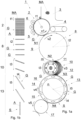
- Fig. 1a shows an apparatus according to the invention in a preferred embodiment.
- the shown conveying and forming apparatus for forming a stream S of segments comprises a group of conveyors, the conveying and forming apparatus being situated between a rod hopper and a receiving conveyor, the rods MA being cut into individual segments A delivered to the receiving conveyor.
- the conveying and forming apparatus 1 for forming the stream S of the tobacco industry segments A shown in the embodiment in Fig. 1a comprises a first drum conveyor 2 situated under the hopper 3 and is arranged to receive the rods MA and to convey the rods MA in flutes 4. At the circumferential surface 5 of the first drum conveyor 2, there are situated circular knives 6. The circular knives 6 cut the rods MA into individual segments A when conveying the rods MA on the drum conveyor 2, whereas from one rod MA after cutting a group G of the segments A is formed.
- Fig. 1b shows the successive stages of conveying and cutting the rod MA, forming, conveying and reconfiguring the group G of the segments A for individual conveyors of the conveying and forming apparatus 1.
- the group G of the segments A formed after cutting the rod MA comprises the segments A situated coaxially, the group G of the segments A is conveyed further to the first transfer point N1.
- the first flutes 4 are arranged on the circumferential surface 5 of the first drum conveyor 2 with the first pitch t1.
- the second drum conveyor 8 is provided with second flutes 9 for receiving the groups G of the segments A from the first drum conveyor 2.
- the second flutes 9 are arranged with a second pitch t2 greater than the first pitch t1.
- the distance between adjacent moving groups G is altered from a distance equal to the pitch t1 to a distance equal to the pitch t2.
- the coaxial configuration of the segments A in the group G remains unchanged, whereas the circumferential speed v2 of the second flutes 9 is greater than the circumferential speed v1 of the first flutes 4, the second circumferential speed v2 of the second flutes 9 is at least twice the first circumferential speed v1 of the first flutes 4, in the embodiment shown, the second speed v2 is more than ten times the first speed v1.
- the segments A in the group G of the second flute 9 remain in the same coaxial configuration with an increased distance equal to the pitch t2.
- the group G of the segments A is transferred to the third conveyor 10 at the second transfer point N2.
- the third conveyor 10 comprises separating discs 11, the axes of rotation m of the individual separating discs 11 being situated parallel to each other, in the embodiment shown, the axes of rotation m of the separating discs 11 are situated non-coaxially. In the case of forming two streams as shown in Fig. 2 , the separating discs can be situated coaxially in pairs.
- the third conveyor 10 is a separating disc conveyor, whereas the number of separating discs 11 in the third conveyor 10 corresponds to the number of segments A in the group G.
- the separating disc 11 has third flutes 12 for receiving the segments A from the second drum conveyor 8, the third flutes 12 of the separating disc 11 being arranged with a third pitch t3, the third flutes 12 of the adjacent separating discs 11 being situated non-coaxially and holding the segments A in the group G in a non-coaxial configuration, the segments A of the group G being positioned along a spiral line.
- the separating discs 11 of the third conveyor 10 have different diameters, and the pitch t3 for each separating disc 11 is selected such that the third flutes 12 are equally spaced from one another over the circumference of the separating disc 11.
- the diameters of the individual separating discs 11 vary slightly, and the third pitch t3 for the individual separating discs 11 has a different value.
- the separating discs 11 have a uniform rotational speed, and the third circumferential speed v3 is dependent on the diameter of the separating disc 11, the speed v3 of the third flutes being similar to the speed v2 of the second flutes 9 on the second drum conveyor 8, whereas one of the separating discs 11 may have a speed equal to the speed v2.
- the segments A are transferred to the fourth conveyor 13 at the third transfer point N3, whereas for each segment A in the group G this will be a different point N3 shifted relative to the adjacent point by a small value resulting from the non-coaxiality of the separating discs 11.
- the fourth drum conveyor 13 is provided with fourth flutes 14 for receiving the segments A from the third conveyor 10 and aligning the segments A, whereas the alignment is understood as aligning the segments A one after another along a circular path on the circumferential surface 13A of the fourth drum conveyor 13A.
- the spiral configuration is changed to a circular configuration.
- the segments A of the group G are successively received from the third conveyor 10 in successive fourth flutes 14, the fourth flutes 14 being arranged with a fourth pitch t4, while the groups G are arranged with a fifth pitch t5, the fourth pitch t4 being equal to the fifth pitch t5 divided by the number of segments in the group G.
- the speed v4 of movement of the fourth flutes 14 is equal to the speed v3 of movement of the third flutes 12 on the third drum conveyor 10.
- the fourth flutes 14 hold the segments A in the group G in the spiral configuration on the circumferential surface 15 of the drum conveyor 13.
- the fourth drum conveyor 13 is provided with an aligning mechanism 16 known from the prior art, arranged to shift the segments A axially in the flutes 14 of the fourth drum conveyor 13.
- the aligning mechanism 16 aligns the segments A in the circular configuration on the circumferential surface 15 of the drum conveyor 13, which is shown in Fig. 1b in a developed view as a rectilinear stream S.
- the resulting stream S is transferred towards the fourth transfer point N4 and further to the receiving conveyor 17.
- the speed v5 of the flutes of the receiving conveyor 17 is equal to the speed v4 of the flutes 14 of the fourth drum conveyor 13.
- Fig. 2 shows, in simplified terms, the formation of two streams of the segments A using the conveying and forming apparatus 1.
- the method according to the invention is shown with diagrammatic illustration of the steps wherein the rods MA are fed.
- the rods MA are then cut into the segments A to form the groups G.
- the groups G of the segments A are spaced at a greater distance than that with which the rods MA are conveyed.
- the segments A are separated transversely, in the direction of conveying, and are then spaced transversely so that, in the preferred embodiment, at least two segments A occupy a coaxial position.
- the group G comprises two subgroups of segments in a developed view situated slantwise, and spirally on the surface of the conveyor.
- the segments A are aligned to a configuration in a developed view of two rectilinear streams S of the segments A, i.e. to the circular configuration on the conveyor, transferred to further production stages.
Landscapes
- Manufacturing Of Cigar And Cigarette Tobacco (AREA)
- Specific Conveyance Elements (AREA)
Abstract
Description
- The object of the invention is a conveying and forming method and apparatus for forming a stream of tobacco industry segments. The method and apparatus according to the invention are used in the tobacco industry for the production of segmented products.
- Conveying apparatuses known from the prior art convey rods that are cut during conveying, convey the segments formed after cutting the rods and form at least one stream of segments. European patent applications
EP1016350A2 ,EP1213105A2 ,EP1584247A1 ,EP1757195A2 relate to a process of manufacturing cigarettes with a segmented mouthpiece and of manufacturing multi-segment filter rods, these applications disclose drum conveyor systems in which the cutting of the rods into segments, the separation of the segments transversely to their axis and the alignment of the segments are carried out. Disclosed apparatuses form a single stream and two parallel moving streams. The disclosed apparatuses are capable of producing a stream or streams of short segments only by doubling the segment cutting, separating and aligning units. - Several types of segments made of different materials are used in currently manufactured smoker products, whereas such products may comprise even up to five types of material and there is a demand for shorter and shorter segments in the filter section of the product. For example, there is a demand to form a single stream of 10mm long segments which are cut in half during the cutting of the intermediate product, resulting in 5mm long segments in the finished product. Known apparatuses for conveying segments and forming a stream are arranged to separate several segments from one another. An engineering problem occurring in the prior art is to obtain a separated stream of segments obtained from a single semi-finished product, segments being separated transversely, in the direction of conveying, where the semi-finished product is cut, for example, into 8, 10, 12 segments, the segments being 10mm or less in length. Forming a stream of short segments is problematic due to the need to hold the segment under vacuum for a short length and the need to transfer such short segments between drum conveyors. A transverse separation to the axis of the segments is hardly feasible with short segments as the segments may rub against each other, creating an increased frictional force. The frictional force acting transversely to the segment axis can cause segment rotation or damage.
- The object of the invention is a conveying and forming apparatus for forming a stream of tobacco industry segments, comprising: a first drum conveyor having first flutes for conveying groups of the segments, the first flutes being arranged with a first pitch and holding the segments in the group in a coaxial configuration.
- The apparatus according to the invention is further provided with a second drum conveyor having second flutes for receiving the groups of the segments from the first drum conveyor, the second flutes being arranged with a second pitch and holding the segments in the group in the coaxial configuration, the second pitch being greater than the first pitch. The apparatus according to the invention is further provided with a third conveyor comprising separating discs, the separating disc having third flutes for receiving the segments from the second drum conveyor, the third flutes of the separating disc being arranged with a third pitch, the separating discs having axes of rotation positioned non-coaxially, and at least two third flutes of the separating discs being positioned non-coaxially, the third flutes holding the segments in the group in a non-coaxial spiral configuration. The apparatus according to the invention is further provided with a fourth drum conveyor having fourth flutes for receiving the segments from the third conveyor, the fourth flutes being arranged with a fourth pitch and arranged to shift the segments in a non-coaxial spiral configuration, the fourth drum conveyor being provided with an aligning mechanism arranged to shift the segments in the fourth flutes in a direction parallel to the axis of rotation of the fourth drum conveyor so as to change the non-coaxial spiral configuration on the circumferential surface of the drum conveyor to a circular configuration, forming at least one stream of the segments.
- Preferably, the apparatus according to the invention is characterised in that the second pitch of the second flutes of the second drum conveyor is at least twice as great as the first pitch of the first drum conveyor.
- The object of the invention is further a method of forming at least one stream of the tobacco industry segments, comprising steps wherein a group of segments is conveyed in a coaxial configuration of the segments in the first flutes of the first drum conveyor, the first flutes being arranged with the first pitch. Subsequently, the group of the segments is transferred to the second flute of the second drum conveyor and then the group is conveyed in the second flute of the second drum conveyor while maintaining the coaxial configuration of the segments, the second pitch of the second flutes of the second drum conveyor being greater than the first pitch of the first flutes of the first drum conveyor. In the next step, the segments of the group from the second flute of the second drum conveyor are transferred to the third flutes of the separating discs of the third conveyor and the configuration of the segments in the group is changed to the non-coaxial spiral configuration, and then the group of the segments in the non-coaxial spiral configuration is conveyed on the third conveyor provided with the separating discs, the third flutes of the separating disc being arranged with the third pitch, after which the segments are transferred to the fourth flutes of the fourth drum conveyor in the non-coaxial spiral configuration. In further steps, the segments are conveyed in the fourth flutes of the fourth drum conveyor in the non-coaxial spiral configuration, the segments are aligned on the fourth drum conveyor by means of the aligning mechanism by shifting the segments axially in the fourth flutes in a direction parallel to the rotation axis of the fourth drum conveyor so as to change the non-coaxial spiral configuration on the circumferential surface of the drum conveyor to the circular configuration, thus forming at least one stream of the segments.
- Preferably, the method according to the invention is characterised in that the segments are conveyed on the second drum conveyor with the second pitch which is at least twice as great as the first pitch on the first drum conveyor.
- An advantage of the invention is achieving the axial separation of all segments using a single drum conveyor.
- The object of the invention is shown in more detail in a preferred embodiment in a drawing in which:
- Fig. 1a
- shows a conveying and forming apparatus according to the invention,
- Fig. 1b
- shows the stages of forming a segment stream,
- Fig. 2
- shows the stages of forming two streams.
-
Fig. 1a shows an apparatus according to the invention in a preferred embodiment. The shown conveying and forming apparatus for forming a stream S of segments comprises a group of conveyors, the conveying and forming apparatus being situated between a rod hopper and a receiving conveyor, the rods MA being cut into individual segments A delivered to the receiving conveyor. - The conveying and forming
apparatus 1 for forming the stream S of the tobacco industry segments A shown in the embodiment inFig. 1a comprises afirst drum conveyor 2 situated under thehopper 3 and is arranged to receive the rods MA and to convey the rods MA influtes 4. At thecircumferential surface 5 of thefirst drum conveyor 2, there are situatedcircular knives 6. Thecircular knives 6 cut the rods MA into individual segments A when conveying the rods MA on thedrum conveyor 2, whereas from one rod MA after cutting a group G of the segments A is formed.Fig. 1b shows the successive stages of conveying and cutting the rod MA, forming, conveying and reconfiguring the group G of the segments A for individual conveyors of the conveying and formingapparatus 1. The group G of the segments A formed after cutting the rod MA comprises the segments A situated coaxially, the group G of the segments A is conveyed further to the first transfer point N1. Thefirst flutes 4 are arranged on thecircumferential surface 5 of thefirst drum conveyor 2 with the first pitch t1. - The
second drum conveyor 8 is provided withsecond flutes 9 for receiving the groups G of the segments A from thefirst drum conveyor 2. Thesecond flutes 9 are arranged with a second pitch t2 greater than the first pitch t1. At the first transfer point N1, the distance between adjacent moving groups G is altered from a distance equal to the pitch t1 to a distance equal to the pitch t2. After transferring the group G to thedrum conveyor 8, the coaxial configuration of the segments A in the group G remains unchanged, whereas the circumferential speed v2 of thesecond flutes 9 is greater than the circumferential speed v1 of thefirst flutes 4, the second circumferential speed v2 of thesecond flutes 9 is at least twice the first circumferential speed v1 of thefirst flutes 4, in the embodiment shown, the second speed v2 is more than ten times the first speed v1. The segments A in the group G of thesecond flute 9 remain in the same coaxial configuration with an increased distance equal to the pitch t2. The group G of the segments A is transferred to thethird conveyor 10 at the second transfer point N2. - The
third conveyor 10 comprises separatingdiscs 11, the axes of rotation m of the individual separatingdiscs 11 being situated parallel to each other, in the embodiment shown, the axes of rotation m of the separatingdiscs 11 are situated non-coaxially. In the case of forming two streams as shown inFig. 2 , the separating discs can be situated coaxially in pairs. Thethird conveyor 10 is a separating disc conveyor, whereas the number of separatingdiscs 11 in thethird conveyor 10 corresponds to the number of segments A in the group G. The separatingdisc 11 hasthird flutes 12 for receiving the segments A from thesecond drum conveyor 8, thethird flutes 12 of the separatingdisc 11 being arranged with a third pitch t3, thethird flutes 12 of the adjacent separatingdiscs 11 being situated non-coaxially and holding the segments A in the group G in a non-coaxial configuration, the segments A of the group G being positioned along a spiral line. The separatingdiscs 11 of thethird conveyor 10 have different diameters, and the pitch t3 for each separatingdisc 11 is selected such that thethird flutes 12 are equally spaced from one another over the circumference of the separatingdisc 11. The diameters of the individual separatingdiscs 11 vary slightly, and the third pitch t3 for the individual separatingdiscs 11 has a different value. The separatingdiscs 11 have a uniform rotational speed, and the third circumferential speed v3 is dependent on the diameter of the separatingdisc 11, the speed v3 of the third flutes being similar to the speed v2 of thesecond flutes 9 on thesecond drum conveyor 8, whereas one of the separatingdiscs 11 may have a speed equal to the speed v2. The segments A are transferred to thefourth conveyor 13 at the third transfer point N3, whereas for each segment A in the group G this will be a different point N3 shifted relative to the adjacent point by a small value resulting from the non-coaxiality of the separatingdiscs 11. - The
fourth drum conveyor 13 is provided withfourth flutes 14 for receiving the segments A from thethird conveyor 10 and aligning the segments A, whereas the alignment is understood as aligning the segments A one after another along a circular path on the circumferential surface 13A of the fourth drum conveyor 13A. On thefourth drum conveyor 13, the spiral configuration is changed to a circular configuration. The segments A of the group G are successively received from thethird conveyor 10 in successivefourth flutes 14, thefourth flutes 14 being arranged with a fourth pitch t4, while the groups G are arranged with a fifth pitch t5, the fourth pitch t4 being equal to the fifth pitch t5 divided by the number of segments in the group G. The speed v4 of movement of thefourth flutes 14 is equal to the speed v3 of movement of thethird flutes 12 on thethird drum conveyor 10. Thefourth flutes 14 hold the segments A in the group G in the spiral configuration on thecircumferential surface 15 of thedrum conveyor 13. Thefourth drum conveyor 13 is provided with analigning mechanism 16 known from the prior art, arranged to shift the segments A axially in theflutes 14 of thefourth drum conveyor 13. In the embodiment shown, thealigning mechanism 16 aligns the segments A in the circular configuration on thecircumferential surface 15 of thedrum conveyor 13, which is shown inFig. 1b in a developed view as a rectilinear stream S. The resulting stream S is transferred towards the fourth transfer point N4 and further to the receivingconveyor 17. The speed v5 of the flutes of the receivingconveyor 17 is equal to the speed v4 of theflutes 14 of thefourth drum conveyor 13. -
Fig. 2 shows, in simplified terms, the formation of two streams of the segments A using the conveying and formingapparatus 1. The method according to the invention is shown with diagrammatic illustration of the steps wherein the rods MA are fed. The rods MA are then cut into the segments A to form the groups G. The groups G of the segments A are spaced at a greater distance than that with which the rods MA are conveyed. In a further step, the segments A are separated transversely, in the direction of conveying, and are then spaced transversely so that, in the preferred embodiment, at least two segments A occupy a coaxial position. In the embodiment shown, the group G comprises two subgroups of segments in a developed view situated slantwise, and spirally on the surface of the conveyor. Subsequently, the segments A are aligned to a configuration in a developed view of two rectilinear streams S of the segments A, i.e. to the circular configuration on the conveyor, transferred to further production stages.
Claims (4)
- A conveying and forming apparatus (1) for forming a stream (S) of tobacco industry segments (A), comprising:a first drum conveyor (2) having first flutes (4) for conveying groups (G) of the segments (A), the first flutes (4) being arranged with a first pitch (t1) and holding the segments (A) in the group (G) in a coaxial configuration,a second drum conveyor (8) having second flutes (9), for receiving the groups (G) of the segments (A) from the first drum conveyor (2), the second flutes (9) being arranged with a second pitch (t2) and holding the segments (A) in the group (G) in the coaxial configuration, the second pitch (t2) being greater than the first pitch (t1),a third conveyor (10) comprising separating discs (11), the separating disc (11) having third flutes (12) for receiving the segments (A) from the second drum conveyor (8), the third flutes (12) of the separating disc (11) being arranged with a third pitch (t3), the separating discs (11) having axes of rotation (m) positioned non-coaxially, and at least two third flutes (12) of the separating discs (11) being positioned non-coaxially, the third flutes (12) holding the segments (A) in the group (G) in a non-coaxial spiral configuration,a fourth drum conveyor (13) having fourth flutes (10) for receiving the segments (A) from the third conveyor (10), the fourth flutes (14) being arranged with a fourth pitch (t4) and arranged to shift the segments (A) in a non-coaxial spiral configuration, the fourth drum conveyor (13) being provided with an aligning mechanism (16) arranged to shift the segments (A) in the fourth flutes (14) in a direction parallel to the axis of rotation (n) of the fourth drum conveyor (13) so as to change the non-coaxial spiral configuration on the circumferential surface (15) of the drum conveyor (13) to a circular configuration, forming at least one stream (S) of the segments (A).
- The apparatus as in claim 1, characterised in that the second pitch (t2) of the second flutes (9) of the second drum conveyor (8) is at least twice as great as the first pitch (t1) of the first drum conveyor (2).
- A method of forming at least one stream (S) of the tobacco industry segments (A), comprising steps whereina group (G) of segments (A) is conveyed in a coaxial configuration of the segments (A) in the first flutes (4) of the first drum conveyor (2), the first flutes (4) being arranged with the first pitch (t1),the group (G) of the segments (A) is transferred to the second flute (9) of the second drum conveyor (8),the group (G) is conveyed in the second flute (9) of the second drum conveyor (8) while maintaining the coaxial configuration of the segments (A), the second pitch (t2) of the second flutes (9) of the second drum conveyor (8) being greater than the first pitch (t1) of the first flutes (4) of the first drum conveyor (2),the segments (A) of the group (G) from the second flute (9) of the second drum conveyor (8) are transferred to the third flutes (12) of the separating discs (11) of the third conveyor (10) and the configuration of the segments (A) in the group (G) is changed to the non-coaxial spiral configuration,the group (G) of the segments (A) in the non-coaxial spiral configuration is conveyed on the third conveyor (10) provided with separating discs (11), the third flutes (12) of the separating disc (11) being arranged with the third pitch (t3),the segments (A) are transferred to the fourth flutes (14) of the fourth drum conveyor (13) in the non-coaxial spiral configuration,the segments (A) are conveyed in the fourth flutes (14) of the fourth drum conveyor (13) in the non-coaxial spiral configuration,the segments (A) are aligned on the fourth drum conveyor (13) by means of the aligning mechanism (16) by shifting the segments (A) axially in the fourth flutes (14) in a direction parallel to the rotation axis (n) of the fourth drum conveyor (13) so as to change the non-coaxial spiral configuration on the circumferential surface (15) of the drum conveyor (13) to the circular configuration, thus forming at least one stream (S) of the segments (A).
- The method as in claim 3, characterised in that the segments (A) are conveyed on the second drum conveyor (8) with the second pitch (t2) which is at least twice as great as the first pitch (t1) on the first drum conveyor (2).
Priority Applications (4)
| Application Number | Priority Date | Filing Date | Title |
|---|---|---|---|
| EP23183439.1A EP4487701B1 (en) | 2023-07-04 | 2023-07-04 | Conveying and forming method and apparatus for forming a stream of tobacco industry segments |
| PL23183439.1T PL4487701T3 (en) | 2023-07-04 | 2023-07-04 | Conveying and forming method and apparatus for forming a stream of tobacco industry segments |
| US19/488,895 US20260114499A1 (en) | 2023-07-04 | 2024-07-01 | Conveying and forming method and apparatus for forming a stream of tobacco industry segments |
| PCT/EP2024/068469 WO2025008295A1 (en) | 2023-07-04 | 2024-07-01 | Conveying and forming method and apparatus for forming a stream of tobacco industry segments |
Applications Claiming Priority (1)
| Application Number | Priority Date | Filing Date | Title |
|---|---|---|---|
| EP23183439.1A EP4487701B1 (en) | 2023-07-04 | 2023-07-04 | Conveying and forming method and apparatus for forming a stream of tobacco industry segments |
Publications (2)
| Publication Number | Publication Date |
|---|---|
| EP4487701A1 true EP4487701A1 (en) | 2025-01-08 |
| EP4487701B1 EP4487701B1 (en) | 2026-02-11 |
Family
ID=87847999
Family Applications (1)
| Application Number | Title | Priority Date | Filing Date |
|---|---|---|---|
| EP23183439.1A Active EP4487701B1 (en) | 2023-07-04 | 2023-07-04 | Conveying and forming method and apparatus for forming a stream of tobacco industry segments |
Country Status (4)
| Country | Link |
|---|---|
| US (1) | US20260114499A1 (en) |
| EP (1) | EP4487701B1 (en) |
| PL (1) | PL4487701T3 (en) |
| WO (1) | WO2025008295A1 (en) |
Citations (7)
| Publication number | Priority date | Publication date | Assignee | Title |
|---|---|---|---|---|
| US3270601A (en) * | 1963-11-14 | 1966-09-06 | Hauni Werke Koerber & Co Kg | Apparatus for manipulating rod-like material |
| GB2028099A (en) * | 1978-08-03 | 1980-03-05 | Molins Ltd | Filter attachment machines |
| EP1016350A2 (en) | 1998-12-10 | 2000-07-05 | Hauni Maschinenbau AG | Method and apparatus for manufacturing cigarettes with multiple compartment filters |
| EP1213105A2 (en) | 2000-12-06 | 2002-06-12 | Hauni Maschinenbau AG | Apparatus and method for changing cutting means |
| EP1584247A1 (en) | 2004-04-06 | 2005-10-12 | Hauni Maschinenbau AG | Filter assembling machine |
| ITBO20060330A1 (en) * | 2006-05-03 | 2006-08-02 | Gd Spa | SUPPLY UNIT FOR FILTER CUTS |
| DE102007030275A1 (en) * | 2007-06-28 | 2009-01-02 | Hauni Maschinenbau Ag | Device for manufacturing of smoking article, particularly filter tipped cigarette, comprises filter manufacture unit for section-wise manufacturing of filter rods, where transfer unit is provided for direct transfer of filter rods |
-
2023
- 2023-07-04 EP EP23183439.1A patent/EP4487701B1/en active Active
- 2023-07-04 PL PL23183439.1T patent/PL4487701T3/en unknown
-
2024
- 2024-07-01 WO PCT/EP2024/068469 patent/WO2025008295A1/en not_active Ceased
- 2024-07-01 US US19/488,895 patent/US20260114499A1/en active Pending
Patent Citations (8)
| Publication number | Priority date | Publication date | Assignee | Title |
|---|---|---|---|---|
| US3270601A (en) * | 1963-11-14 | 1966-09-06 | Hauni Werke Koerber & Co Kg | Apparatus for manipulating rod-like material |
| GB2028099A (en) * | 1978-08-03 | 1980-03-05 | Molins Ltd | Filter attachment machines |
| EP1016350A2 (en) | 1998-12-10 | 2000-07-05 | Hauni Maschinenbau AG | Method and apparatus for manufacturing cigarettes with multiple compartment filters |
| EP1757195A2 (en) | 1998-12-10 | 2007-02-28 | Hauni Maschinenbau Aktiengesellschaft | Method and apparatus for manufacturing cigarettes with multiple compartment filters |
| EP1213105A2 (en) | 2000-12-06 | 2002-06-12 | Hauni Maschinenbau AG | Apparatus and method for changing cutting means |
| EP1584247A1 (en) | 2004-04-06 | 2005-10-12 | Hauni Maschinenbau AG | Filter assembling machine |
| ITBO20060330A1 (en) * | 2006-05-03 | 2006-08-02 | Gd Spa | SUPPLY UNIT FOR FILTER CUTS |
| DE102007030275A1 (en) * | 2007-06-28 | 2009-01-02 | Hauni Maschinenbau Ag | Device for manufacturing of smoking article, particularly filter tipped cigarette, comprises filter manufacture unit for section-wise manufacturing of filter rods, where transfer unit is provided for direct transfer of filter rods |
Also Published As
| Publication number | Publication date |
|---|---|
| WO2025008295A1 (en) | 2025-01-09 |
| PL4487701T3 (en) | 2026-04-20 |
| US20260114499A1 (en) | 2026-04-30 |
| EP4487701B1 (en) | 2026-02-11 |
Similar Documents
| Publication | Publication Date | Title |
|---|---|---|
| CN107105763B (en) | Equipment for the manufacture of multi-strip strips and transfer units for the transfer of strip-shaped element series | |
| EP3376883B1 (en) | Centering device for rod shaped articles of the tobacco industry | |
| US10653176B2 (en) | Apparatus for manufacturing of multi-element rods of tobacco industry | |
| EP4487701B1 (en) | Conveying and forming method and apparatus for forming a stream of tobacco industry segments | |
| EP4138586A1 (en) | Method and unit for feeding rod-shaped segments | |
| CN110650638B (en) | Device and method for transferring rod-shaped articles and device for converting the articles | |
| EP4374714A1 (en) | Feeding module for feeding segments in the form of rod-like articles, apparatus and method for manufacturing multi-segment articles | |
| US20190183164A1 (en) | Apparatus for manufacturing of multi-element rods of tobacco industry | |
| RU2842907C2 (en) | Method of producing rod-like articles for tobacco industry, device for manufacturing rod-like articles and system for manufacturing rod-like articles | |
| WO2021250489A1 (en) | Method and machine for making multisegment articles | |
| US3872779A (en) | Manufacture of cigarette filters | |
| EP4374713A1 (en) | Apparatus and method for manufacturing multi-segment articles | |
| EP4480328B1 (en) | Pushing drum for the tobacco-processing industry and method for operating same | |
| EP4291047B1 (en) | Method of manufacturing rod-like articles for tobacco industry, apparatus for manufacturing rod-like articles and system for manufacturing rod-like articles | |
| EP4444117A1 (en) | Method and system of manufacturing multisegment articles | |
| CN120265154A (en) | Device for making multi-segment objects | |
| PL234109B1 (en) | Device for production of multi-segment bars in the tobacco industry products and the transporting equipment for conveying bar-like series elements |
Legal Events
| Date | Code | Title | Description |
|---|---|---|---|
| PUAI | Public reference made under article 153(3) epc to a published international application that has entered the european phase |
Free format text: ORIGINAL CODE: 0009012 |
|
| STAA | Information on the status of an ep patent application or granted ep patent |
Free format text: STATUS: THE APPLICATION HAS BEEN PUBLISHED |
|
| AK | Designated contracting states |
Kind code of ref document: A1 Designated state(s): AL AT BE BG CH CY CZ DE DK EE ES FI FR GB GR HR HU IE IS IT LI LT LU LV MC ME MK MT NL NO PL PT RO RS SE SI SK SM TR |
|
| STAA | Information on the status of an ep patent application or granted ep patent |
Free format text: STATUS: REQUEST FOR EXAMINATION WAS MADE |
|
| 17P | Request for examination filed |
Effective date: 20250707 |
|
| GRAP | Despatch of communication of intention to grant a patent |
Free format text: ORIGINAL CODE: EPIDOSNIGR1 |
|
| STAA | Information on the status of an ep patent application or granted ep patent |
Free format text: STATUS: GRANT OF PATENT IS INTENDED |
|
| RIC1 | Information provided on ipc code assigned before grant |
Ipc: A24C 5/47 20060101AFI20251103BHEP Ipc: A24D 3/02 20060101ALI20251103BHEP |
|
| INTG | Intention to grant announced |
Effective date: 20251117 |
|
| GRAS | Grant fee paid |
Free format text: ORIGINAL CODE: EPIDOSNIGR3 |
|
| GRAA | (expected) grant |
Free format text: ORIGINAL CODE: 0009210 |
|
| STAA | Information on the status of an ep patent application or granted ep patent |
Free format text: STATUS: THE PATENT HAS BEEN GRANTED |
|
| AK | Designated contracting states |
Kind code of ref document: B1 Designated state(s): AL AT BE BG CH CY CZ DE DK EE ES FI FR GB GR HR HU IE IS IT LI LT LU LV MC ME MK MT NL NO PL PT RO RS SE SI SK SM TR |
|
| REG | Reference to a national code |
Ref country code: CH Ref legal event code: F10 Free format text: ST27 STATUS EVENT CODE: U-0-0-F10-F00 (AS PROVIDED BY THE NATIONAL OFFICE) Effective date: 20260211 Ref country code: GB Ref legal event code: FG4D |
|
| REG | Reference to a national code |
Ref country code: DE Ref legal event code: R096 Ref document number: 602023011784 Country of ref document: DE |
|
| REG | Reference to a national code |
Ref country code: IE Ref legal event code: FG4D |