EP4485756A1 - Permanentmagnetanordnung für eine axialflussmaschine eines türantriebs und axialflussmaschine - Google Patents
Permanentmagnetanordnung für eine axialflussmaschine eines türantriebs und axialflussmaschine Download PDFInfo
- Publication number
- EP4485756A1 EP4485756A1 EP23181715.6A EP23181715A EP4485756A1 EP 4485756 A1 EP4485756 A1 EP 4485756A1 EP 23181715 A EP23181715 A EP 23181715A EP 4485756 A1 EP4485756 A1 EP 4485756A1
- Authority
- EP
- European Patent Office
- Prior art keywords
- permanent magnet
- magnet arrangement
- arrangement
- machine
- machine axis
- Prior art date
- Legal status (The legal status is an assumption and is not a legal conclusion. Google has not performed a legal analysis and makes no representation as to the accuracy of the status listed.)
- Pending
Links
Images

Classifications
-
- H—ELECTRICITY
- H02—GENERATION; CONVERSION OR DISTRIBUTION OF ELECTRIC POWER
- H02K—DYNAMO-ELECTRIC MACHINES
- H02K1/00—Details of the magnetic circuit
- H02K1/06—Details of the magnetic circuit characterised by the shape, form or construction
- H02K1/22—Rotating parts of the magnetic circuit
- H02K1/27—Rotor cores with permanent magnets
- H02K1/2793—Rotors axially facing stators
- H02K1/2795—Rotors axially facing stators the rotor consisting of two or more circumferentially positioned magnets
-
- E—FIXED CONSTRUCTIONS
- E05—LOCKS; KEYS; WINDOW OR DOOR FITTINGS; SAFES
- E05F—DEVICES FOR MOVING WINGS INTO OPEN OR CLOSED POSITION; CHECKS FOR WINGS; WING FITTINGS NOT OTHERWISE PROVIDED FOR, CONCERNED WITH THE FUNCTIONING OF THE WING
- E05F15/00—Power-operated mechanisms for wings
- E05F15/60—Power-operated mechanisms for wings using electrical actuators
- E05F15/603—Power-operated mechanisms for wings using electrical actuators using rotary electromotors
-
- H—ELECTRICITY
- H02—GENERATION; CONVERSION OR DISTRIBUTION OF ELECTRIC POWER
- H02K—DYNAMO-ELECTRIC MACHINES
- H02K21/00—Synchronous motors having permanent magnets; Synchronous generators having permanent magnets
- H02K21/12—Synchronous motors having permanent magnets; Synchronous generators having permanent magnets with stationary armatures and rotating magnets
- H02K21/24—Synchronous motors having permanent magnets; Synchronous generators having permanent magnets with stationary armatures and rotating magnets with magnets axially facing the armatures, e.g. hub-type cycle dynamos
-
- H—ELECTRICITY
- H02—GENERATION; CONVERSION OR DISTRIBUTION OF ELECTRIC POWER
- H02K—DYNAMO-ELECTRIC MACHINES
- H02K29/00—Motors or generators having non-mechanical commutating devices, e.g. discharge tubes or semiconductor devices
- H02K29/03—Motors or generators having non-mechanical commutating devices, e.g. discharge tubes or semiconductor devices with a magnetic circuit specially adapted for avoiding torque ripples or self-starting problems
Definitions
- the invention relates to a permanent magnet arrangement for use as a rotor or stator of an axial flux machine, in particular an axial flux machine of a door drive, wherein the permanent magnet arrangement has a plurality of permanent magnets arranged in a ring around a machine axis and each magnetized in an axial direction running parallel to the machine axis, wherein permanent magnets arranged adjacent to one another each have an oppositely oriented polarization, wherein each permanent magnet extends from an inner surface of the permanent magnet facing the machine axis to an outer surface of the permanent magnet, wherein each permanent magnet has a first side surface and a second side surface opposite the first side surface, wherein the two side surfaces connect the inner surface and the outer surface to one another, wherein the first side surface of each permanent magnet is oriented in the direction of the second side surface of a respective immediately adjacent permanent magnet.
- the invention also relates to an axial flux machine with a coil arrangement and a permanent magnet arrangement.
- axial flux machines and in particular of brushless axial flux machines for door drives is known from the state of the art and is described, for example, in the publication EP 3 974 610 A1
- the magnetic flux runs through the permanent magnet arrangement and the coil arrangement axially to the Rotational axis of the motor, which forms the machine axis.
- the permanent magnet arrangement forms part of a stator of the axial flux machine and the coil arrangement forms part of a rotor of the axial flux machine or the permanent magnet arrangement forms part of the rotor of the axial flux machine and the coil arrangement forms part of the stator of the axial flux machine.
- the permanent magnets of the permanent magnet arrangement and coils of the coil arrangement are usually arranged in a ring around the machine axis.
- the permanent magnets are aligned so that one of the poles of each permanent magnet is closer to the coil arrangement than the other pole, so that magnetic field lines running between the north pole and the south pole within the respective permanent magnet run parallel to the machine axis.
- the permanent magnets usually have an approximately trapezoidal base area, with dimensions of the base area being a multiple of a height of the respective permanent magnet. Straight lines through side edges of the base area usually run through a point on the rotational axis or the machine axis, so that an inner edge of the base area is shorter than an outer edge of the base area.
- the permanent magnets therefore have the shape of an approximately trapezoidal prism.
- the inner edge and the outer edge are often also shaped like a circular segment, so that the base area forms a ring segment.
- the permanent magnets of the permanent magnet arrangement according to the invention each have an inner surface, an outer surface and opposing side surfaces. These can be clearly separated from one another.
- cogging forces are magnetic interference forces and are caused by interactions between the permanent magnets and coil cores or stator teeth, which are made of iron or another material with good magnetic conductivity.
- Various measures are known from the state of the art to reduce these cogging forces.
- the permanent magnets are adjusted from the approximately trapezoidal base area so that the straight lines through the side edges no longer run through the axis of rotation, or that shapes deviating from the trapezoidal shape are selected, for example with bent side edges.
- beveling the magnetic edges is to adjust the permanent magnets from the trapezoidal base area so that the side edges are tilted against the straight lines running through the axis of rotation by a so-called bevel angle.
- the side edges of the permanent magnets have the same displacement angle for each connection point on the respective side edge or at least for each connection point on sections of the side edges when the side edge is bent. This is also called the bevel angle.
- the object of the invention is to further develop the designs of the magnetic edges known from the prior art in such a way that the cogging torques are further reduced.
- each first side surface has a continuously curved course from the inner surface to the outer surface, so that the course of the first side surface is either concave or convex.
- inventive design of at least one of the two side surfaces exploits this knowledge to further reduce the cogging torques. For this purpose, instead of the design with a constant displacement or helix angle, at least one of the side surfaces is designed in such a way that the helix angle increases continuously with the distance from the machine axis and is curved.
- the cogging torques can advantageously be further reduced by increasing the curvature of the first side surface from the inner surface to the outer surface. It has been shown that by designing a side surface in this way with a cogging torque that increases disproportionately depending on the distance from the machine axis, Helix angles allow the cogging torques to be reduced particularly well.
- every second side surface has a continuously curved profile from the inner surface to the outer surface, so that the profile of the second side surface is either convex or concave.
- the second side surface is also inclined or tilted or slanted and curved.
- a curvature of the second side surface increases from the inner surface to the outer surface. In this way, the helix angle of the second side surface changes disproportionately in relation to the distance of the respective section from the machine axis, as with the first side surface.
- the invention provides that the profile of the second side surface is concave when the profile of the first side surface is convex and vice versa.
- the second side surface is inclined or tilted or beveled in the same direction as the first side surface.
- the cogging torques can be further reduced by increasing a distance, determined in a circumferential direction of the permanent magnet arrangement, between the first side surface and the second side surface of each permanent magnet from the inner surface to the outer surface.
- the first displacement angle increases in relation to the distance of the respective displacement point from the machine axis more than the second displacement angle decreases.
- the invention provides that all cutting planes of each permanent magnet that are perpendicular to the machine axis are congruent. As a result, all first connecting lines of the same length have the same first displacement angle and all second connecting lines of the same length have the same second displacement angle. This results in both side surfaces being curved or stepped exclusively in one circumferential direction.
- each permanent magnet runs in sections along an inner ring circumference of the permanent magnet arrangement and the outer surface of each permanent magnet runs in sections along an outer ring circumference of the permanent magnet arrangement.
- the ring-shaped design of the permanent magnet arrangement results in a magnetic field that is particularly suitable for the axial flux machine.
- the permanent magnets are designed in such a way and the inner surfaces and the outer surfaces of each permanent magnet are aligned with each other in such a way that in at least one cutting plane perpendicular to the machine axis, a radially extending through a A ray running from the inner distance center of the inner surface of each permanent magnet intersects the outer surface or the outer ring circumference of the respective permanent magnet at a distance from an outer distance center, wherein the inner distance center and the outer distance center are determined by the average path length between end points of the respective inner surface or the respective outer surface.
- the invention provides that the outer surface is displaced in the circumferential direction relative to the inner surface. This displacement relates to the approximately trapezoidal basic shape of the permanent magnets known from the prior art.
- the invention provides that a length of the outer surface in the circumferential direction is greater than a length of the inner surface. In this way, the available installation space can be fully utilized.
- the cogging torques can be further reduced by designing the permanent magnets and aligning them relative to one another in such a way that, in at least one cutting plane perpendicular to the machine axis, a beam running radially from the machine axis through an outermost point in the circumferential direction of the outer surface of a first permanent magnet runs in sections in the corresponding cutting plane of a second permanent magnet arranged immediately adjacent to the first permanent magnet. Adjacent permanent magnets As a result, they overlap in sections when viewed from the machine axis.
- the outer surface and the inner surface of the permanent magnet do not merge continuously into one another.
- the inner surface and the outer surface can advantageously be clearly demarcated from one another and from the side surfaces.
- the side surfaces do not merge continuously into the inner surface and the outer surface.
- the invention also relates to an axial flux machine with a coil arrangement and a permanent magnet arrangement according to one of the preceding claims, wherein the coil arrangement has a plurality of electrical machine coils arranged adjacent to one another in a ring around the machine axis, wherein the coil arrangement is arranged axially displaced, adjacent to the permanent magnet arrangement.
- the axial flux machine is advantageously a brushless axial flux machine. Such axial flux machines are particularly suitable for use with door or window drives.
- the invention provides that the inner ring circumference and the outer ring circumference of the permanent magnet arrangement correspond essentially to corresponding ring circumferences of the coil arrangement. In this way, a particularly compact design of the axial flux machine can be achieved. According to the invention, it is advantageously provided that the axial flow machine can be used in a swing door, sliding door or revolving door drive.
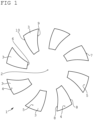
- Figure 1 a schematic representation of a permanent magnet arrangement with permanent magnets that have a continuous course of the side surfaces
- Figure 2 a schematic representation of an axial flow machine.
- a permanent magnet arrangement 1 for an axial flux machine of a door drive is shown schematically.
- the permanent magnet arrangement 1 has several permanent magnets 3 arranged adjacent to one another in a ring around a machine axis 2.
- a magnetic north pole 4 and a magnetic south pole 5 of each permanent magnet 3 are arranged such that within the respective permanent magnet 3, magnetic field lines running between the north pole 4 and the south pole 5 run parallel to the machine axis 2, with magnetic field directions of adjacent permanent magnets 3 running in opposite directions.
- Each permanent magnet 3 extends from an inner surface 6 facing the machine axis 2 to an outer surface 7.
- the inner surface 6 and the outer surface 7 are each connected by the north pole 4 to the south pole 5. extending side surfaces 8 of the respective permanent magnet 3.
- First side surfaces 9 and second side surfaces 10 have a continuous curved course in a circumferential direction of the permanent magnet arrangement 1 from the inner surface 6 to the outer surface 7, wherein the first side surface 9 is concavely curved and the second side surface 10 is convexly curved. In this case, a distance between the side surfaces 9, 10 in the circumferential direction of the permanent magnet arrangement 1 increases in the radial direction.
- each permanent magnet 3 is curved and run along an inner ring circumference and an outer ring circumference of the permanent magnet arrangement 1.
- the outer surfaces 7 are displaced relative to the inner surface 6 in the circumferential direction.
- a length of the outer surfaces 7 in the circumferential direction is greater than a length of the inner surfaces 6.
- Figure 2 shows schematically a partially sectioned axial flow machine 11 with a coil arrangement 12 and a permanent magnet arrangement 1.
- the permanent magnet arrangement 1 corresponds to the one shown in Figure 1 illustrated design. In this illustration it can be seen that all cutting planes of each permanent magnet 3 that are perpendicular to the machine axis 2 are congruent.
- the coil arrangement 12 has a plurality of electrical Machine coils 13 that are wound around iron cores 14 of the coil arrangement 12.
- the coil arrangement 12 is axially displaced, arranged adjacent to the permanent magnet arrangement 1.
- the axial flux machine 11 also has a circuit board 15 for electrically contacting the coils 13.
Landscapes
- Engineering & Computer Science (AREA)
- Power Engineering (AREA)
- Permanent Field Magnets Of Synchronous Machinery (AREA)
Abstract
Die Erfindung betrifft eine Permanentmagnetanordnung (1) zur Verwendung als Rotor oder Stator einer Axialflussmaschine, insbesondere einer Axialflussmaschine eines Türantriebs. Die Permanentmagnetanordnung (1) weist mehrere um eine Maschinenachse (2) ringförmig angeordnete und jeweils in einer parallel zu der Mittelachse (2) verlaufenden axialen Richtung magnetisierte Permanentmagnete (3) auf. Benachbart zueinander angeordnete Permanentmagnete (3) weisen jeweils eine entgegengesetzt ausgerichtete Polarisierung auf. Jeder Permanentmagnet (3) erstreckt sich von einer der Maschinenachse (2) zugewandten Innenfläche (6) des Permanentmagneten (3) zu einer Außenfläche (7) des Permanentmagneten (3) weg. Jeder Permanentmagnet (3) weist eine erste Seitenfläche (9) und eine der ersten Seitenfläche (9) gegenüberliegende zweite Seitenfläche (10) auf. Die beiden Seitenflächen (9, 10) verbinden die Innenfläche (6) und die Außenfläche (7) miteinander. Die erste Seitenfläche (9) jedes Permanentmagneten (3) sind in Richtung auf die zweite Seitenfläche (10) eines jeweils unmittelbar benachbarten Permanentmagneten (3) ausgerichtet. Jede erste Seitenfläche (9) weist einen stetig gekrümmten Verlauf von der Innenfläche (6) bis zu der Außenfläche (7) hin auf, sodass der Verlauf der ersten Seitenfläche (9) entweder konkav oder konvex ist.
Description
- Die Erfindung betrifft eine Permanentmagnetanordnung zur Verwendung als Rotor oder Stator einer Axialflussmaschine, insbesondere einer Axialflussmaschine eines Türantriebs, wobei die Permanentmagnetanordnung mehrere um eine Maschinenachse ringförmig angeordnete und jeweils in einer parallel zu der Maschinenachse verlaufenden axialen Richtung magnetisierte Permanentmagnete aufweist, wobei benachbart zueinander angeordnete Permanentmagnete jeweils eine entgegengesetzt ausgerichtete Polarisierung aufweisen, wobei sich jeder Permanentmagnet von einer der Maschinenachse zugewandten Innenfläche des Permanentmagneten zu einer Außenfläche des Permanentmagneten weg erstreckt, wobei jeder Permanentmagnet eine erste Seitenfläche und eine der ersten Seitenfläche gegenüberliegende zweite Seitenfläche aufweist, wobei die beiden Seitenflächen die Innenfläche und die Außenfläche miteinander verbinden, wobei die erste Seitenfläche jedes Permanentmagneten in Richtung auf die zweite Seitenfläche eines jeweils unmittelbar benachbarten Permanentmagneten ausgerichtet sind. Die Erfindung betrifft auch eine Axialflussmaschine mit einer Spulenanordnung und einer Permanentmagnetanordnung.
- Die Verwendung von Axialflussmaschinen und insbesondere von bürstenlosen Axialflussmaschinen für Türantriebe ist aus dem Stand der Technik bekannt und wird beispielsweise in der Druckschrift
EP 3 974 610 A1 beschrieben. Bei derartigen Axialflussmaschinen verläuft der magnetische Fluss durch die Permanentmagnetanordnung und die Spulenanordnung axial zur Drehachse des Motors, die die Maschinenachse bildet. Die Permanentmagnetanordnung bildet einen Teil eines Stators der Axialflussmaschine und die Spulenanordnung bildet einen Teil eines Rotors der Axialflussmaschine oder die Permanentmagnetanordnung bildet einen Teil des Rotors der Axialflussmaschine und die Spulenanordnung bildet einen Teil des Stators der Axialflussmaschine. Die Permanentmagneten der Permanentmagnetanordnung und Spulen der Spulenanordnung sind dabei üblicherweise ringförmig um die Maschinenachse herum angeordnet. Die Permanentmagneten sind so ausgerichtet, dass einer der Pole jedes Permanentmagneten näher zu der Spulenanordnung liegt als der andere Pol, sodass innerhalb des jeweiligen Permanentmagneten zwischen dem Nordpol und dem Südpol verlaufende magnetische Feldlinien parallel zu der Maschinenachse verlaufen. Die Permanentmagneten weisen üblicherweise eine näherungsweise trapezförmige Grundfläche auf, wobei Abmessungen der Grundfläche ein Vielfaches einer Höhe des jeweiligen Permanentmagneten aufweisen. Geraden durch Seitenkanten der Grundfläche verlaufen dabei üblicherweise durch einen Punkt der Drehachse bzw. der Maschinenachse, sodass eine Innenkante der Grundfläche kürzer ist als eine Außenkante der Grundfläche. Die Permanentmagnete weisen dadurch eine Form eines näherungsweise trapezförmigen Prismas auf. Häufig sind die Innenkante und die Außenkante auch kreisabschnittsförmig ausgebildet, sodass die Grundfläche ein Ringsegment bildet. - Die Permanentmagnete der erfindungsgemäßen Permanentmagnetanordnung weisen jeweils eine Innenfläche, eine Außenfläche und einander gegenüberliegende Seitenflächen auf. Dabei können diese erkennbar voneinander abgegrenzt werden.
- Es ist bekannt, dass beim Betrieb dieser Axialflussmaschinen sogenannte Rastkräfte oder Rastmomente auftreten, die im Betrieb zu einer erhöhten Geräuschentwicklung und Vibration führen und den Gesamtwirkungsgrad der Maschine senken. Die Rastkräfte sind magnetische Störkräfte und entstehen durch Wechselwirkungen zwischen den Permanentmagneten und Spulenkernen bzw. Statorzähnen, die aus Eisen oder einem anderen Material mit guter magnetischer Leitfähigkeit bestehen. Um diese Rastkräfte zu reduzieren sind aus dem Stand der Technik unterschiedliche Maßnahmen bekannt.
- Eine dieser Maßnahmen ist die sogenannte "Schrägung der Magnetkanten" der Permanentmagnete. Bei dieser Maßnahme werden die Permanentmagnete ausgehend von der näherungsweise trapezförmigen Grundfläche so angepasst, dass die Geraden durch die Seitenkanten nicht mehr durch die Drehachse verlaufen oder dass von der Trapezform abweichende Formgebungen mit beispielsweise geknickt verlaufenden Seitenkanten gewählt werden. Eine aus dem Stand der Technik bekannte Möglichkeit zur Schrägung der Magnetkanten besteht darin, die Permanentmagneten ausgehend von der trapezförmigen Grundfläche so anzupassen, dass die Seitenkanten um einen sogenannten Schrägungswinkel gegen die durch die Drehachse verlaufenden Geraden verkippt werden. Die Seitenkanten der Permanentmagneten weisen dabei für jeden Verbindungspunkt auf der jeweiligen Seitenkante oder zumindest für jeden Verbindungspunkt auf Abschnitten der Seitenkanten bei geknicktem Verlauf der Seitenkante den gleichen Verschiebungswinkel auf. Dieser wird auch Schrägungswinkel genannt.
- Als Aufgabe der Erfindung wird es angesehen, die aus dem Stand der Technik bekannten Ausgestaltungen der Magnetkanten so weiterzuentwickeln, dass die Rastmomente weiter reduziert werden.
- Diese Aufgabe wird erfindungsgemäß dadurch gelöst, dass jede erste Seitenfläche einen stetig gekrümmten Verlauf von der Innenfläche bis zu der Außenfläche hin aufweist, sodass der Verlauf der ersten Seitenfläche entweder konkav oder konvex ist. Bei Untersuchungen mit herkömmlichen Permanentmagneten mit näherungsweise trapezförmiger Grundfläche mit kreisabschnittsförmig ausgebildeter Innen- und Außenkante hat sich herausgestellt, dass ein Beitrag einzelner Abschnitte der Permanentmagneten zu den durch diese Permanentmagneten erzeugten Rastmomente abhängig vom Abstand des jeweiligen Abschnitts von der Maschinenachse ist. Zudem hat sich herausgestellt, dass dieser Beitrag nicht linear von dem Abstand abhängt. Durch die erfindungsgemäße Ausgestaltung mindestens einer der beiden Seitenflächen wird diese Erkenntnis ausgenutzt, um die Rastmomente weiter zu verringern. Dazu wird anstelle der Ausgestaltung mit einem konstanten Verschiebungs- bzw. Schrägungswinkel mindestens eine der Seitenflächen so ausgestaltet, dass der Schrägungswinkel mit dem Abstand von der Maschinenachse kontinuierlich zunimmt und gekrümmt ausgebildet ist.
- Die Rastmomente können vorteilhafterweise dadurch weiter reduziert werden, dass eine Krümmung der ersten Seitenfläche von der Innenfläche zu der Außenfläche hin zunimmt. Es hat sich gezeigt, dass durch eine derartige Ausgestaltung einer Seitenfläche mit einem in Abhängigkeit des Abstands von der Maschinenachse überproportional größer werdenden Schrägungswinkel die Rastmomente besonders gut reduziert werden können.
- Vorteilhafterweise ist erfindungsgemäß vorgesehen, dass jede zweite Seitenfläche einen stetig gekrümmten Verlauf von der Innenfläche bis zu der Außenfläche hin aufweist, sodass der Verlauf der zweiten Seitenfläche entweder konvex oder konkav ist. Auf diese Weise ist die zweite Seitenfläche ebenfalls geneigt bzw. verkippt oder geschrägt und gekrümmt ausgestaltet.
- Bei einer besonders vorteilhaften Ausgestaltung der erfindungsgemäßen Permanentmagnetanordnung ist vorgesehen, dass eine Krümmung der zweiten Seitenfläche von der Innenfläche zu der Außenfläche hin zunimmt. Auf diese Weise verändert sich der Schrägungswinkel der zweiten Seitenfläche wie bei der ersten Seitenfläche überproportional im Verhältnis zum Abstand des jeweiligen Abschnitts von der Maschinenachse.
- Vorteilhafterweise ist erfindungsgemäß vorgesehen, dass der Verlauf der zweiten Seitenfläche konkav ist, wenn der Verlauf der ersten Seitenfläche konvex ist und umgekehrt. Auf diese Weise ist die zweite Seitenfläche in die gleiche Richtung geneigt bzw. verkippt oder geschrägt wie die erste Seitenfläche.
- Die Rastmomente können dadurch weiter reduziert werden, dass ein in einer Umfangsrichtung der Permanentmagnetanordnung bestimmter Abstand der ersten Seitenfläche zu der zweiten Seitenfläche jedes Permanentmagneten zueinander von der Innenfläche zu der Außenfläche hin zunimmt. Der erste Verschiebungswinkel nimmt im Verhältnis zu dem Abstand des jeweiligen Verschiebungspunkts zu der Maschinenachse bei dieser Ausgestaltung also stärker zu, als der zweite Verschiebungswinkel abnimmt.
- Vorteilhafterweise ist erfindungsgemäß vorgesehen, dass sämtliche senkrecht auf der Maschinenachse stehende Schnittebenen jedes Permanentmagneten deckungsgleich sind. Hierdurch weisen sämtliche erste Verbindungslinien gleicher Länge den gleichen ersten Verschiebungswinkel und sämtliche zweite Verbindungslinien gleicher Länge den gleichen zweiten Verschiebungswinkel auf. Dadurch ergibt sich ein ausschließlich in einer Umfangsrichtung gekrümmter oder gestufter Verlauf beider Seitenflächen.
- Bei einer besonders vorteilhaften Ausgestaltung der erfindungsgemäßen Permanentmagnetanordnung ist vorgesehen, dass die Innenfläche jedes Permanentmagneten abschnittsweise entlang eines Innenringumfangs der Permanentmagnetanordnung und die Außenfläche jedes Permanentmagneten abschnittsweise entlang eines Außenringumfangs der Permanentmagnetanordnung verläuft. Durch die ringförmige Ausgestaltung der Permanentmagnetanordnung ergibt sich ein für den der Axialflussmaschine besonders geeignetes Magnetfeld.
- Bei einer besonders vorteilhaften Ausgestaltung der erfindungsgemäßen Permanentmagnetanordnung ist vorgesehen, dass die Permanentmagnete so ausgestaltet und die Innenflächen und die Außenflächen jedes Permanentmagneten so zueinander ausgerichtet sind, dass in mindestens einer senkrecht auf der Maschinenachse stehenden Schnittebene ein ausgehend von der Maschinenachse radial durch einen Innenabstandsmittelpunkt der Innenfläche jedes Permanentmagneten verlaufender Strahl die Außenfläche bzw. den Außenringumfang des jeweiligen Permanentmagneten beabstandet zu einem Außenabstandsmittelpunkt schneidet, wobei der Innenabstandsmittelpunkt und der Außenabstandsmittelpunkt durch die mittlere Weglänge zwischen Endpunkten der jeweiligen Innenfläche bzw. der jeweiligen Außenfläche bestimmt sind.
- Um einen durchgehend progressiv gekrümmten Verlauf der Seitenflächen zu erreichen ist erfindungsgemäß vorgesehen, dass die Außenfläche relativ zu der Innenfläche in der Umfangsrichtung verschoben ist. Diese Verschiebung bezieht sich auf die aus dem Stand der Technik bekannte näherungsweise trapezförmige Grundform der Permanentmagnete.
- Vorteilhafterweise ist erfindungsgemäß vorgesehen, dass eine Länge der Außenfläche in der Umfangrichtung größer ist als eine Länge der Innenfläche. Auf diese Weise kann der zur Verfügung stehende Bauraum vollständig ausgenutzt werden.
- Die Rastmomente können dadurch weiter reduziert werden, dass die Permanentmagnete so ausgestaltet sind und relativ zueinander ausgerichtet sind, dass in mindestens einer senkrecht auf der Maschinenachse stehenden Schnittebene ein ausgehend von der Maschinenachse radial durch einen in der Umfangsrichtung äußersten Punkt der Außenfläche eines ersten Permanentmagneten laufender Strahl abschnittsweise in der korrespondierenden Schnittebene eines zu dem ersten Permanentmagneten unmittelbar benachbart angeordneten zweiten Permanentmagneten verläuft. Benachbarte Permanentmagnete überlappen sich dadurch von der Maschinenachse aus gesehen abschnittsweise.
- Erfindungsgemäß ist vorteilhafterweise vorgesehen, dass die Außenfläche und die Innenfläche des Permanentmagneten nicht kontinuierlich ineinander übergehen. Die Innenfläche und die Außenfläche können vorteilhafterweise gegeneinander und gegenüber den Seitenflächen erkennbar voneinander abgegrenzt werden. Vorteilhafterweise gehen die Seitenflächen nicht kontinuierlich in die Innenfläche und die Außenfläche über.
- Die Erfindung betrifft auch eine Axialflussmaschine mit einer Spulenanordnung und einer Permanentmagnetanordnung gemäß einem der voranstehenden Ansprüche, wobei die Spulenanordnung mehrere benachbart zueinander ringförmig um die Maschinenachse angeordnete elektrische Maschinenspulen aufweist, wobei die Spulenanordnung axial verschoben, benachbart zu der Permanentmagnetanordnung angeordnet ist. Vorteilhafterweise handelt s sich bei der Axialflussmaschine um eine bürstenlose Axialflussmaschine. Derartige Axialflussmaschinen eignen sich besonders gut für die Verwendung mit Tür- oder Fensterantrieben.
- Vorteilhafterweise ist erfindungsgemäß vorgesehen, dass der Innenringumfang und der Außenringumfang der Permanentmagnetanordnung im Wesentlichen korrespondierenden Ringumfängen der Spulenanordnung entsprechen. Auf diese Weise kann ein besonders kompakter Aufbau der Axialflussmaschine erreicht werden. Erfindungsgemäß ist vorteilhafterweise vorgesehen, dass die Axialflussmaschine in einem Schwenktürflügel- oder Schiebetür- oder Karusselltürantrieb verwendbar ist.
- Weitere vorteilhafte Ausgestaltungen der erfindungsgemäßen Permanentmagnetanordnung werden anhand von in der Zeichnung dargestellten Ausführungsbeispielen näher erläutert.
-
Figur 1 eine schematische Darstellung einer Permanentmagnetanordnung mit Permanentmagneten, die einen kontinuierlichen Verlauf der Seitenflächen aufweisen und -
Figur 2 eine schematische Darstellung einer Axialflussmaschine. - In der
Figur 1 ist schematisch eine Permanentmagnetanordnung 1 für eine Axialflussmaschine eines Türantriebs dargestellt. Die Permanentmagnetanordnung 1 weist mehrere benachbart zueinander ringförmig um eine Maschinenachse 2 angeordnete Permanentmagnete 3 auf. Ein magnetischer Nordpol 4 und ein magnetischer Südpol 5 jedes Permanentmagneten 3 ist so angeordnet, dass innerhalb des jeweiligen Permanentmagneten 3 zwischen dem Nordpol 4 und dem Südpol 5 verlaufende magnetische Feldlinien parallel zu der Maschinenachse 2 verlaufen, wobei Magnetfeldrichtungen benachbarter Permanentmagnete 3 entgegengesetzt verlaufen. - Jeder Permanentmagnet 3 erstreckt sich von einer der Maschinenachse 2 zugewandten Innenfläche 6 zu einer Außenfläche 7 weg. Die Innenfläche 6 und die Außenfläche 7 sind durch sich jeweils von dem Nordpol 4 zu dem Südpol 5 erstreckende Seitenflächen 8 des jeweiligen Permanentmagneten 3 verbunden.
- Erste Seitenflächen 9 und zweite Seitenflächen 10 weisen einen kontinuierlich in einer Umfangsrichtung der Permanentmagnetanordnung 1 gekrümmten Verlauf von der Innenfläche 6 zu der Außenfläche 7 hin auf, wobei die erste Seitenfläche 9 konkav gekrümmt ist und die zweite Seitenfläche 10 konvex gekrümmt ist. Dabei nimmt ein in der Umfangsrichtung der Permanentmagnetanordnung 1 bestimmter Abstand der Seitenflächen 9, 10 zueinander in der radialen Richtung zu.
- Die Innenfläche 6 und die Außenfläche 7 jedes Permanentmagneten 3 sind gekrümmt und verlaufen entlang eines Innenringumfangs und eines Außenringumfangs der Permanentmagnetanordnung 1. Dabei sind die Außenflächen 7 relativ zu den Innenfläche 6 in der Umfangsrichtung verschoben. Zudem ist eine Länge der Außenflächen 7 in der Umfangrichtung größer ist als eine Länge der Innenflächen 6.
-
Figur 2 zeigt schematisch eine teilweise geschnitten dargestellte Axialflussmaschine 11 mit einer Spulenanordnung 12 und einer Permanentmagnetanordnung 1. Die Permanentmagnetanordnung 1 entspricht dabei der inFigur 1 dargestellten Ausgestaltung. In dieser Darstellung ist erkennbar, dass sämtliche senkrecht auf der Maschinenachse 2 stehende Schnittebenen jedes Permanentmagneten 3 deckungsgleich sind. - Die Spulenanordnung 12 weist mehrere benachbart zueinander ringförmig um die Maschinenachse 2 angeordnete elektrische Maschinenspulen 13 auf, die um Eisenkerne 14 der Spulenanordnung 12 gewickelt sind. Die Spulenanordnung 12 ist axial verschoben, benachbart zu der Permanentmagnetanordnung 1 angeordnet. Die Axialflussmaschine 11 weist zudem eine Platine 15 zur elektrischen Kontaktierung der Spulen 13 auf.
- In der Zeichnung sind jeweils exemplarisch einzelne mehrerer gleichartiger Elemente mit einem Bezugszeichen gekennzeichnet.
Claims (14)
- Permanentmagnetanordnung (1) zur Verwendung als Rotor oder Stator einer Axialflussmaschine (11), insbesondere einer Axialflussmaschine (11) eines Türantriebs, wobei die Permanentmagnetanordnung (1) mehrere um eine Maschinenachse (2) ringförmig angeordnete und jeweils in einer parallel zu der Maschinenachse (2) verlaufenden axialen Richtung magnetisierte Permanentmagnete (3) aufweist, wobei benachbart zueinander angeordnete Permanentmagnete (3) jeweils eine entgegengesetzt ausgerichtete Polarisierung aufweisen, wobei sich jeder Permanentmagnet (3) von einer der Maschinenachse (2) zugewandten Innenfläche (6) des Permanentmagneten (3) zu einer Außenfläche (7) des Permanentmagneten (3) weg erstreckt, wobei jeder Permanentmagnet (3) eine erste Seitenfläche (9) und eine der ersten Seitenfläche (9) gegenüberliegende zweite Seitenfläche (10) aufweist, wobei die beiden Seitenflächen (9, 10) die Innenfläche (6) und die Außenfläche (7) miteinander verbinden, wobei die erste Seitenfläche (9) jedes Permanentmagneten (3) in Richtung auf die zweite Seitenfläche (10) eines jeweils unmittelbar benachbarten Permanentmagneten (3) ausgerichtet sind, dadurch gekennzeichnet, dass jede erste Seitenfläche (9) einen stetig gekrümmten Verlauf von der Innenfläche (6) bis zu der Außenfläche (7) hin aufweist, sodass der Verlauf der ersten Seitenfläche (9) entweder konkav oder konvex ist.
- Permanentmagnetanordnung (1) gemäß Anspruch 1, dadurch gekennzeichnet, dass eine Krümmung der ersten Seitenfläche (9) von der Innenfläche (6) zu der Außenfläche (7) hin zunimmt.
- Permanentmagnetanordnung (1) gemäß Anspruch 1 oder Anspruch 2, dadurch gekennzeichnet, dass jede zweite Seitenfläche (10) einen stetig gekrümmten Verlauf von der Innenfläche (6) bis zu der Außenfläche (7) hin aufweist, sodass der Verlauf der zweiten Seitenfläche (10) entweder konvex oder konkav ist.
- Permanentmagnetanordnung (1) gemäß Anspruch 3, dadurch gekennzeichnet, dass eine Krümmung der zweiten Seitenfläche (10) von der Innenfläche (6) zu der Außenfläche (7) hin zunimmt.
- Permanentmagnetanordnung (1) gemäß Anspruch 3 oder Anspruch 4, dadurch gekennzeichnet, dass der Verlauf der zweiten Seitenfläche (10) konkav ist, wenn der Verlauf der ersten Seitenfläche (9) konvex ist und umgekehrt.
- Permanentmagnetanordnung (1) gemäß einem der voranstehenden Ansprüche, dadurch gekennzeichnet, dass ein in einer Umfangsrichtung der Permanentmagnetanordnung (1) bestimmter Abstand der ersten Seitenfläche (9) zu der zweiten Seitenfläche (10) jedes Permanentmagneten (3) zueinander von der Innenfläche (6) zu der Außenfläche (7) hin zunimmt.
- Permanentmagnetanordnung (1) gemäß einem der voranstehenden Ansprüche, dadurch gekennzeichnet, dass sämtliche Schnittflächen jedes Permanentmagneten (3) durch senkrecht auf der Maschinenachse (2) stehende Schnittebenen deckungsgleich sind.
- Permanentmagnetanordnung (1) gemäß einem der voranstehenden Ansprüche, dadurch gekennzeichnet, dass die Innenfläche (6) jedes Permanentmagneten (3) abschnittsweise entlang eines Innenringumfangs der Permanentmagnetanordnung (1) und die Außenfläche (7) jedes Permanentmagneten (3) abschnittsweise entlang eines Außenringumfangs der Permanentmagnetanordnung (1) verläuft.
- Permanentmagnetanordnung (1) gemäß einem der voranstehenden Ansprüche, dadurch gekennzeichnet, dass eine Länge der Außenfläche (7) in der Umfangrichtung größer ist als eine Länge der Innenfläche (6).
- Permanentmagnetanordnung (1) gemäß einem der voranstehenden Ansprüche, dadurch gekennzeichnet, dass die Permanentmagnete (3) so ausgestaltet und die Innenflächen (6) und die Außenflächen (7) jedes Permanentmagneten (3) so zueinander ausgerichtet sind, dass in mindestens einer senkrecht auf der Maschinenachse (2) stehenden Schnittebene ein ausgehend von der Maschinenachse (2) radial durch einen Innenabstandsmittelpunkt der Innenfläche (6) jedes Permanentmagneten (3) verlaufender Strahl die Außenfläche (7) und/oder den Außenringumfang des jeweiligen Permanentmagneten (3) beabstandet zu einem Außenabstandsmittelpunkt schneidet, wobei der Innenabstandsmittelpunkt und der Außenabstandsmittelpunkt durch die mittlere Weglänge zwischen Endpunkten der jeweiligen Innenfläche (6) bzw. der jeweiligen Außenfläche (7) bestimmt sind.
- Permanentmagnetanordnung (1) gemäß einem der voranstehenden Ansprüche, dadurch gekennzeichnet, dass die Permanentmagnete (3) so ausgestaltet sind und relativ zueinander ausgerichtet sind, dass in mindestens einer senkrecht auf der Maschinenachse (2) stehenden Schnittebene ein ausgehend von der Maschinenachse (2) radial durch einen in der Umfangsrichtung äußersten Punkt der Außenfläche (7) eines ersten Permanentmagneten (3) laufender Strahl abschnittsweise in der korrespondierenden Schnittebene eines zu dem ersten Permanentmagneten (3) unmittelbar benachbart angeordneten zweiten Permanentmagneten (3) verläuft.
- Axialflussmaschine (11) mit einer Spulenanordnung (12) und mit einer Permanentmagnetanordnung (1) gemäß einem der voranstehenden Ansprüche, wobei die Spulenanordnung (12) mehrere benachbart zueinander ringförmig um die Maschinenachse (2) angeordnete elektrische Maschinenspulen (13) aufweist, wobei die Spulenanordnung (12) axial verschoben benachbart zu der Permanentmagnetanordnung (1) angeordnet ist.
- Axialflussmaschine (11) gemäß Anspruch 12, dadurch gekennzeichnet, dass der Innenringumfang und der Außenringumfang der Permanentmagnetanordnung (1) im Wesentlichen korrespondierenden Ringumfängen der Spulenanordnung (12) entsprechen.
- Axialflussmaschine (11) gemäß Anspruch 12 oder Anspruch 13, dadurch gekennzeichnet, dass die Axialflussmaschine (11) in einem Schwenkflügeltür- oder Schiebetür- oder Karusselltürantrieb verwendbar ist.
Priority Applications (2)
| Application Number | Priority Date | Filing Date | Title |
|---|---|---|---|
| EP23181715.6A EP4485756A1 (de) | 2023-06-27 | 2023-06-27 | Permanentmagnetanordnung für eine axialflussmaschine eines türantriebs und axialflussmaschine |
| US18/752,150 US20250007341A1 (en) | 2023-06-27 | 2024-06-24 | Permanent magnet arrangement for an axial flux machine of a door drive and axial flux machine |
Applications Claiming Priority (1)
| Application Number | Priority Date | Filing Date | Title |
|---|---|---|---|
| EP23181715.6A EP4485756A1 (de) | 2023-06-27 | 2023-06-27 | Permanentmagnetanordnung für eine axialflussmaschine eines türantriebs und axialflussmaschine |
Publications (1)
| Publication Number | Publication Date |
|---|---|
| EP4485756A1 true EP4485756A1 (de) | 2025-01-01 |
Family
ID=87003267
Family Applications (1)
| Application Number | Title | Priority Date | Filing Date |
|---|---|---|---|
| EP23181715.6A Pending EP4485756A1 (de) | 2023-06-27 | 2023-06-27 | Permanentmagnetanordnung für eine axialflussmaschine eines türantriebs und axialflussmaschine |
Country Status (2)
| Country | Link |
|---|---|
| US (1) | US20250007341A1 (de) |
| EP (1) | EP4485756A1 (de) |
Citations (6)
| Publication number | Priority date | Publication date | Assignee | Title |
|---|---|---|---|---|
| JPS50111611U (de) * | 1974-02-22 | 1975-09-11 | ||
| EP0734112A1 (de) * | 1995-03-24 | 1996-09-25 | Kone Oy | Dämpfungswicklung für einen Aufzugsmotor |
| WO2009037374A1 (en) * | 2007-09-21 | 2009-03-26 | Kone Corporation | Electric motor |
| EP3176914A1 (de) * | 2010-03-31 | 2017-06-07 | Kone Corporation | Elektromotor, hebemaschine und aufzugsystem |
| EP3974610A1 (de) | 2020-09-25 | 2022-03-30 | dormakaba Deutschland GmbH | Antriebseinrichtung zum verschieben eines flügels |
| JP7289535B2 (ja) * | 2020-05-19 | 2023-06-12 | 株式会社アパード | アキシャルギャップモータ |
Family Cites Families (2)
| Publication number | Priority date | Publication date | Assignee | Title |
|---|---|---|---|---|
| DE102020125116A1 (de) * | 2020-09-25 | 2022-03-31 | Dormakaba Deutschland Gmbh | Stator für eine Axialflussmaschine, Axialflussmaschine und Antriebseinrichtung zum Bewegen eines Flügels |
| JP7883493B2 (ja) * | 2021-06-21 | 2026-07-01 | 住友電気工業株式会社 | ステータコア、ステータ、回転電機、及びステータコアの製造方法 |
-
2023
- 2023-06-27 EP EP23181715.6A patent/EP4485756A1/de active Pending
-
2024
- 2024-06-24 US US18/752,150 patent/US20250007341A1/en active Pending
Patent Citations (6)
| Publication number | Priority date | Publication date | Assignee | Title |
|---|---|---|---|---|
| JPS50111611U (de) * | 1974-02-22 | 1975-09-11 | ||
| EP0734112A1 (de) * | 1995-03-24 | 1996-09-25 | Kone Oy | Dämpfungswicklung für einen Aufzugsmotor |
| WO2009037374A1 (en) * | 2007-09-21 | 2009-03-26 | Kone Corporation | Electric motor |
| EP3176914A1 (de) * | 2010-03-31 | 2017-06-07 | Kone Corporation | Elektromotor, hebemaschine und aufzugsystem |
| JP7289535B2 (ja) * | 2020-05-19 | 2023-06-12 | 株式会社アパード | アキシャルギャップモータ |
| EP3974610A1 (de) | 2020-09-25 | 2022-03-30 | dormakaba Deutschland GmbH | Antriebseinrichtung zum verschieben eines flügels |
Also Published As
| Publication number | Publication date |
|---|---|
| US20250007341A1 (en) | 2025-01-02 |
Similar Documents
| Publication | Publication Date | Title |
|---|---|---|
| DE102006025396B4 (de) | A-phasiger bürstenloser Motor | |
| EP0729216A2 (de) | Hybriderregte Synchronmaschine | |
| DE3710658A1 (de) | Elektronisch kommutierter, kollektorloser gleichstrommotor | |
| DE102010046906A1 (de) | Motor | |
| DE112011101641T5 (de) | Rotor einer rotierenden elektrischen Maschine | |
| WO2006106087A1 (de) | Reluktanzmotor | |
| DE102018112971A1 (de) | Permanentmagnet-Synchronmotor und Magnetpositionierungssystem für einen Verdichter einer Fahrzeugklimaanlage | |
| DE102015004669A1 (de) | Motor | |
| EP2725687A1 (de) | Permanenterregte Synchronmaschine | |
| DE102007013738B4 (de) | Elektrische Maschine mit Klauenpolstator | |
| WO2007115907A2 (de) | Antriebs- und auswerteeinrichtung | |
| DE10261763B4 (de) | Rotor für einen Elektromotor | |
| DE102017109256A1 (de) | Statoranordnung | |
| EP3758194B1 (de) | Rotor für eine elektrische maschine, elektrische maschine für ein fahrzeug und fahrzeug | |
| EP4485755A1 (de) | Permanentmagnetanordnung für eine axialflussmaschine eines türantriebs und axialflussmaschine | |
| DE102020212636A1 (de) | Rotor für eine elektrische Maschine, elektrische Maschine und Kraftfahrzeug | |
| DE102021125206A1 (de) | Elektromechanische Rotortopologie zur Steigerung der Effizienz elektrischer Maschinen | |
| DE102016212328A1 (de) | Rotoranordnung einer elektrischen Maschine | |
| WO2022207442A1 (de) | Rotor einer elektrischen asynchronmaschine | |
| DE10313970A1 (de) | Rotor für hohe Drehzahlen und große Ausgangsleistung | |
| DE60014199T2 (de) | Elektrische Drehmaschine | |
| DE102020214207A1 (de) | Rotor mit Kavitäten, Elektromaschine und Kraftfahrzeug | |
| WO2025242293A1 (de) | Rotoranordnung für einen axialflussmotor und axialflussmotor mit einer rotoranordnung | |
| EP4485754A1 (de) | Permanentmagnetanordnung, axialflussmaschine und elektromechanischer antrieb | |
| DE10056875A1 (de) | Rotor für eine elektrische Maschine |
Legal Events
| Date | Code | Title | Description |
|---|---|---|---|
| PUAI | Public reference made under article 153(3) epc to a published international application that has entered the european phase |
Free format text: ORIGINAL CODE: 0009012 |
|
| STAA | Information on the status of an ep patent application or granted ep patent |
Free format text: STATUS: THE APPLICATION HAS BEEN PUBLISHED |
|
| AK | Designated contracting states |
Kind code of ref document: A1 Designated state(s): AL AT BE BG CH CY CZ DE DK EE ES FI FR GB GR HR HU IE IS IT LI LT LU LV MC ME MK MT NL NO PL PT RO RS SE SI SK SM TR |
|
| STAA | Information on the status of an ep patent application or granted ep patent |
Free format text: STATUS: REQUEST FOR EXAMINATION WAS MADE |
|
| 17P | Request for examination filed |
Effective date: 20250617 |