EP4485673A1 - Energiespeichervorrichtung und verfahren zur herstellung der energiespeichervorrichtung - Google Patents
Energiespeichervorrichtung und verfahren zur herstellung der energiespeichervorrichtung Download PDFInfo
- Publication number
- EP4485673A1 EP4485673A1 EP23760181.0A EP23760181A EP4485673A1 EP 4485673 A1 EP4485673 A1 EP 4485673A1 EP 23760181 A EP23760181 A EP 23760181A EP 4485673 A1 EP4485673 A1 EP 4485673A1
- Authority
- EP
- European Patent Office
- Prior art keywords
- storage device
- electrical storage
- lid
- current collector
- electrode assembly
- Prior art date
- Legal status (The legal status is an assumption and is not a legal conclusion. Google has not performed a legal analysis and makes no representation as to the accuracy of the status listed.)
- Pending
Links
Images


Classifications
-
- H—ELECTRICITY
- H01—ELECTRIC ELEMENTS
- H01M—PROCESSES OR MEANS, e.g. BATTERIES, FOR THE DIRECT CONVERSION OF CHEMICAL ENERGY INTO ELECTRICAL ENERGY
- H01M50/00—Constructional details or processes of manufacture of the non-active parts of electrochemical cells other than fuel cells, e.g. hybrid cells
- H01M50/50—Current conducting connections for cells or batteries
- H01M50/572—Means for preventing undesired use or discharge
- H01M50/584—Means for preventing undesired use or discharge for preventing incorrect connections inside or outside the batteries
- H01M50/586—Means for preventing undesired use or discharge for preventing incorrect connections inside or outside the batteries inside the batteries, e.g. incorrect connections of electrodes
-
- H—ELECTRICITY
- H01—ELECTRIC ELEMENTS
- H01G—CAPACITORS; CAPACITORS, RECTIFIERS, DETECTORS, SWITCHING DEVICES, LIGHT-SENSITIVE OR TEMPERATURE-SENSITIVE DEVICES OF THE ELECTROLYTIC TYPE
- H01G11/00—Hybrid capacitors, i.e. capacitors having different positive and negative electrodes; Electric double-layer [EDL] capacitors; Processes for the manufacture thereof or of parts thereof
- H01G11/74—Terminals, e.g. extensions of current collectors
-
- H—ELECTRICITY
- H01—ELECTRIC ELEMENTS
- H01G—CAPACITORS; CAPACITORS, RECTIFIERS, DETECTORS, SWITCHING DEVICES, LIGHT-SENSITIVE OR TEMPERATURE-SENSITIVE DEVICES OF THE ELECTROLYTIC TYPE
- H01G11/00—Hybrid capacitors, i.e. capacitors having different positive and negative electrodes; Electric double-layer [EDL] capacitors; Processes for the manufacture thereof or of parts thereof
- H01G11/78—Cases; Housings; Encapsulations; Mountings
- H01G11/82—Fixing or assembling a capacitive element in a housing, e.g. mounting electrodes, current collectors or terminals in containers or encapsulations
-
- H—ELECTRICITY
- H01—ELECTRIC ELEMENTS
- H01M—PROCESSES OR MEANS, e.g. BATTERIES, FOR THE DIRECT CONVERSION OF CHEMICAL ENERGY INTO ELECTRICAL ENERGY
- H01M10/00—Secondary cells; Manufacture thereof
- H01M10/05—Accumulators with non-aqueous electrolyte
- H01M10/058—Construction or manufacture
- H01M10/0585—Construction or manufacture of accumulators having only flat construction elements, i.e. flat positive electrodes, flat negative electrodes and flat separators
-
- H—ELECTRICITY
- H01—ELECTRIC ELEMENTS
- H01M—PROCESSES OR MEANS, e.g. BATTERIES, FOR THE DIRECT CONVERSION OF CHEMICAL ENERGY INTO ELECTRICAL ENERGY
- H01M50/00—Constructional details or processes of manufacture of the non-active parts of electrochemical cells other than fuel cells, e.g. hybrid cells
- H01M50/10—Primary casings; Jackets or wrappings
- H01M50/102—Primary casings; Jackets or wrappings characterised by their shape or physical structure
- H01M50/103—Primary casings; Jackets or wrappings characterised by their shape or physical structure prismatic or rectangular
-
- H—ELECTRICITY
- H01—ELECTRIC ELEMENTS
- H01M—PROCESSES OR MEANS, e.g. BATTERIES, FOR THE DIRECT CONVERSION OF CHEMICAL ENERGY INTO ELECTRICAL ENERGY
- H01M50/00—Constructional details or processes of manufacture of the non-active parts of electrochemical cells other than fuel cells, e.g. hybrid cells
- H01M50/10—Primary casings; Jackets or wrappings
- H01M50/102—Primary casings; Jackets or wrappings characterised by their shape or physical structure
- H01M50/105—Pouches or flexible bags
-
- H—ELECTRICITY
- H01—ELECTRIC ELEMENTS
- H01M—PROCESSES OR MEANS, e.g. BATTERIES, FOR THE DIRECT CONVERSION OF CHEMICAL ENERGY INTO ELECTRICAL ENERGY
- H01M50/00—Constructional details or processes of manufacture of the non-active parts of electrochemical cells other than fuel cells, e.g. hybrid cells
- H01M50/10—Primary casings; Jackets or wrappings
- H01M50/116—Primary casings; Jackets or wrappings characterised by the material
- H01M50/124—Primary casings; Jackets or wrappings characterised by the material having a layered structure
- H01M50/126—Primary casings; Jackets or wrappings characterised by the material having a layered structure comprising three or more layers
- H01M50/129—Primary casings; Jackets or wrappings characterised by the material having a layered structure comprising three or more layers with two or more layers of only organic material
-
- H—ELECTRICITY
- H01—ELECTRIC ELEMENTS
- H01M—PROCESSES OR MEANS, e.g. BATTERIES, FOR THE DIRECT CONVERSION OF CHEMICAL ENERGY INTO ELECTRICAL ENERGY
- H01M50/00—Constructional details or processes of manufacture of the non-active parts of electrochemical cells other than fuel cells, e.g. hybrid cells
- H01M50/10—Primary casings; Jackets or wrappings
- H01M50/147—Lids or covers
- H01M50/148—Lids or covers characterised by their shape
- H01M50/15—Lids or covers characterised by their shape for prismatic or rectangular cells
-
- H—ELECTRICITY
- H01—ELECTRIC ELEMENTS
- H01M—PROCESSES OR MEANS, e.g. BATTERIES, FOR THE DIRECT CONVERSION OF CHEMICAL ENERGY INTO ELECTRICAL ENERGY
- H01M50/00—Constructional details or processes of manufacture of the non-active parts of electrochemical cells other than fuel cells, e.g. hybrid cells
- H01M50/10—Primary casings; Jackets or wrappings
- H01M50/147—Lids or covers
- H01M50/155—Lids or covers characterised by the material
- H01M50/16—Organic material
-
- H—ELECTRICITY
- H01—ELECTRIC ELEMENTS
- H01M—PROCESSES OR MEANS, e.g. BATTERIES, FOR THE DIRECT CONVERSION OF CHEMICAL ENERGY INTO ELECTRICAL ENERGY
- H01M50/00—Constructional details or processes of manufacture of the non-active parts of electrochemical cells other than fuel cells, e.g. hybrid cells
- H01M50/10—Primary casings; Jackets or wrappings
- H01M50/147—Lids or covers
- H01M50/155—Lids or covers characterised by the material
- H01M50/164—Lids or covers characterised by the material having a layered structure
-
- H—ELECTRICITY
- H01—ELECTRIC ELEMENTS
- H01M—PROCESSES OR MEANS, e.g. BATTERIES, FOR THE DIRECT CONVERSION OF CHEMICAL ENERGY INTO ELECTRICAL ENERGY
- H01M50/00—Constructional details or processes of manufacture of the non-active parts of electrochemical cells other than fuel cells, e.g. hybrid cells
- H01M50/10—Primary casings; Jackets or wrappings
- H01M50/147—Lids or covers
- H01M50/166—Lids or covers characterised by the methods of assembling casings with lids
- H01M50/169—Lids or covers characterised by the methods of assembling casings with lids by welding, brazing or soldering
-
- H—ELECTRICITY
- H01—ELECTRIC ELEMENTS
- H01M—PROCESSES OR MEANS, e.g. BATTERIES, FOR THE DIRECT CONVERSION OF CHEMICAL ENERGY INTO ELECTRICAL ENERGY
- H01M50/00—Constructional details or processes of manufacture of the non-active parts of electrochemical cells other than fuel cells, e.g. hybrid cells
- H01M50/10—Primary casings; Jackets or wrappings
- H01M50/172—Arrangements of electric connectors penetrating the casing
- H01M50/174—Arrangements of electric connectors penetrating the casing adapted for the shape of the cells
- H01M50/176—Arrangements of electric connectors penetrating the casing adapted for the shape of the cells for prismatic or rectangular cells
-
- H—ELECTRICITY
- H01—ELECTRIC ELEMENTS
- H01M—PROCESSES OR MEANS, e.g. BATTERIES, FOR THE DIRECT CONVERSION OF CHEMICAL ENERGY INTO ELECTRICAL ENERGY
- H01M50/00—Constructional details or processes of manufacture of the non-active parts of electrochemical cells other than fuel cells, e.g. hybrid cells
- H01M50/10—Primary casings; Jackets or wrappings
- H01M50/172—Arrangements of electric connectors penetrating the casing
- H01M50/174—Arrangements of electric connectors penetrating the casing adapted for the shape of the cells
- H01M50/178—Arrangements of electric connectors penetrating the casing adapted for the shape of the cells for pouch or flexible bag cells
-
- H—ELECTRICITY
- H01—ELECTRIC ELEMENTS
- H01M—PROCESSES OR MEANS, e.g. BATTERIES, FOR THE DIRECT CONVERSION OF CHEMICAL ENERGY INTO ELECTRICAL ENERGY
- H01M50/00—Constructional details or processes of manufacture of the non-active parts of electrochemical cells other than fuel cells, e.g. hybrid cells
- H01M50/50—Current conducting connections for cells or batteries
- H01M50/531—Electrode connections inside a battery casing
- H01M50/54—Connection of several leads or tabs of plate-like electrode stacks, e.g. electrode pole straps or bridges
-
- H—ELECTRICITY
- H01—ELECTRIC ELEMENTS
- H01M—PROCESSES OR MEANS, e.g. BATTERIES, FOR THE DIRECT CONVERSION OF CHEMICAL ENERGY INTO ELECTRICAL ENERGY
- H01M50/00—Constructional details or processes of manufacture of the non-active parts of electrochemical cells other than fuel cells, e.g. hybrid cells
- H01M50/50—Current conducting connections for cells or batteries
- H01M50/543—Terminals
- H01M50/547—Terminals characterised by the disposition of the terminals on the cells
- H01M50/548—Terminals characterised by the disposition of the terminals on the cells on opposite sides of the cell
-
- H—ELECTRICITY
- H01—ELECTRIC ELEMENTS
- H01M—PROCESSES OR MEANS, e.g. BATTERIES, FOR THE DIRECT CONVERSION OF CHEMICAL ENERGY INTO ELECTRICAL ENERGY
- H01M50/00—Constructional details or processes of manufacture of the non-active parts of electrochemical cells other than fuel cells, e.g. hybrid cells
- H01M50/50—Current conducting connections for cells or batteries
- H01M50/543—Terminals
- H01M50/564—Terminals characterised by their manufacturing process
- H01M50/566—Terminals characterised by their manufacturing process by welding, soldering or brazing
-
- H—ELECTRICITY
- H01—ELECTRIC ELEMENTS
- H01G—CAPACITORS; CAPACITORS, RECTIFIERS, DETECTORS, SWITCHING DEVICES, LIGHT-SENSITIVE OR TEMPERATURE-SENSITIVE DEVICES OF THE ELECTROLYTIC TYPE
- H01G11/00—Hybrid capacitors, i.e. capacitors having different positive and negative electrodes; Electric double-layer [EDL] capacitors; Processes for the manufacture thereof or of parts thereof
- H01G11/78—Cases; Housings; Encapsulations; Mountings
- H01G11/80—Gaskets; Sealings
-
- H—ELECTRICITY
- H01—ELECTRIC ELEMENTS
- H01G—CAPACITORS; CAPACITORS, RECTIFIERS, DETECTORS, SWITCHING DEVICES, LIGHT-SENSITIVE OR TEMPERATURE-SENSITIVE DEVICES OF THE ELECTROLYTIC TYPE
- H01G11/00—Hybrid capacitors, i.e. capacitors having different positive and negative electrodes; Electric double-layer [EDL] capacitors; Processes for the manufacture thereof or of parts thereof
- H01G11/84—Processes for the manufacture of hybrid or EDL capacitors, or components thereof
-
- Y—GENERAL TAGGING OF NEW TECHNOLOGICAL DEVELOPMENTS; GENERAL TAGGING OF CROSS-SECTIONAL TECHNOLOGIES SPANNING OVER SEVERAL SECTIONS OF THE IPC; TECHNICAL SUBJECTS COVERED BY FORMER USPC CROSS-REFERENCE ART COLLECTIONS [XRACs] AND DIGESTS
- Y02—TECHNOLOGIES OR APPLICATIONS FOR MITIGATION OR ADAPTATION AGAINST CLIMATE CHANGE
- Y02E—REDUCTION OF GREENHOUSE GAS [GHG] EMISSIONS, RELATED TO ENERGY GENERATION, TRANSMISSION OR DISTRIBUTION
- Y02E60/00—Enabling technologies; Technologies with a potential or indirect contribution to GHG emissions mitigation
- Y02E60/10—Energy storage using batteries
-
- Y—GENERAL TAGGING OF NEW TECHNOLOGICAL DEVELOPMENTS; GENERAL TAGGING OF CROSS-SECTIONAL TECHNOLOGIES SPANNING OVER SEVERAL SECTIONS OF THE IPC; TECHNICAL SUBJECTS COVERED BY FORMER USPC CROSS-REFERENCE ART COLLECTIONS [XRACs] AND DIGESTS
- Y02—TECHNOLOGIES OR APPLICATIONS FOR MITIGATION OR ADAPTATION AGAINST CLIMATE CHANGE
- Y02P—CLIMATE CHANGE MITIGATION TECHNOLOGIES IN THE PRODUCTION OR PROCESSING OF GOODS
- Y02P70/00—Climate change mitigation technologies in the production process for final industrial or consumer products
- Y02P70/50—Manufacturing or production processes characterised by the final manufactured product
Definitions
- the all-solid-state battery includes an electrode assembly, an electrode terminal, and an outer packaging that seals the electrode assembly.
- the outer packaging includes an exterior film wound around the electrode assembly so as to have an opening, and a lid disposed at the opening.
- An object of the present invention is to provide an electrical storage device in which a current collector can be protected, and a method for manufacturing an electrical storage device.
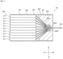
- the electrical storage device 10 includes two electrode terminals 30.
- the electrode terminal 30 is a metal terminal for use in input and output of electrical power in the electrode assembly 20.
- One end part of the electrode terminal 30 is electrically connected to the electrode 21 (positive electrode or negative electrode) in the electrode assembly 20 through the current collector 22.
- the other end part of the electrode terminal 30 protrudes outward from an end edge of the outer packaging 40, for example.
- the exterior film 50 is wound in a state of being in contact with the outer surface of the electrode assembly 20.
- the electrical storage device 10 is an all-solid-state battery, it is necessary to eliminate the space between the electrode assembly 20 and the exterior film 50 from the viewpoint that it is necessary to uniformly apply a high pressure from the outer surface of the battery for exhibiting battery performance, and therefore, it is preferable that the exterior film 50 is wound in a state of being in contact with the outer surface of the electrode assembly 20.
- the base material layer 51 in the exterior film 50 is a layer for imparting heat resistance to the exterior film 50 to suppress generation of pinholes which may occur during processing or distribution.
- the base material layer 51 includes, for example, at least one of a stretched polyester resin layer and a stretched polyamide resin layer.
- the barrier layer 52 can be protected during processing of the exterior film 50 to suppress breakage of the exterior film 50.
- the stretched polyester resin layer is preferably a biaxially stretched polyester resin layer
- the stretched polyamide resin layer is preferably a biaxially stretched polyamide resin layer.
- the thickness of the barrier layer 52 is, for example, preferably 15 to 100 ⁇ m, more preferably 30 to 80 ⁇ m.
- the thickness of the barrier layer 52 is 15 ⁇ m or more, the exterior film 50 is less likely to be broken even if stress is applied by packaging processing.
- the thickness of the barrier layer 52 is 100 ⁇ m or less, an increase in mass of the exterior film 50 can be reduced, and a decrease in weight energy density of the electrical storage device 10 can be suppressed.
- the buffer layer functions as a cushion, so that the exterior film 50 is prevented from being damaged by the impact of falling of the electrical storage device 10 or handling during manufacturing of the electrical storage device 10.
- the root 70X of the first sealed portion 70 may be located on an arbitrary surface of the outer packaging 40.
- the first sealed portion 70 is folded toward the second surface 42 of the outer packaging 40.
- the first sealed portion 70 may protrude outward with respect to the electrode assembly 20 in plan view, or may be folded toward the first surface 41.
- the lid 60 generally has, for example, a cuboid shape, and is made from, a resin material.
- the lid 60 may be formed by, for example, cold-molding the exterior film 50.
- the material for forming the lid 60 include polyester-based resins such as polyethylene terephthalate-based resins and polybutylene terephthalate-based resins, polyolefin-based resins such as polyethylene-based resins, fluorine-based resins and polypropylene-based resins, cyclic polyolefin-based resins, or acid-modified polyolefin-based resins obtained by graft-modifying the polyolefin-based resin with an acid such as maleic anhydride.
- a second sealed portion 80 is formed by heat-sealing the heat-sealable resin layer 53 of the exterior film 50 and a lateral surface of the lid 60 (hereinafter, referred to as a "seal surface 61").
- the sealing strength between the heat-sealable resin layer 53 of the exterior film 50 and the seal surface 61 of the lid 60 may be referred to as sealing strength of the second sealed portion 80.
- the sealing strength of the second sealed portion 80 is the sealing strength between the heat-sealable resin layer 53 and the lid 60 in the long-side portion of the seal surface 61, that is, the seal surface 61 extending in the LR (width) direction in Fig. 1 .
- the exterior film 50 is in the UD (vertical) direction in Fig. 1 with respect to the lid 60, and the sealing strength of the second sealed portion 80 is measured on the basis of a distance of the second sealed portion 80 in the FB (depth) direction.
- the sealing strength of the second sealed portion 80 of the lid 60 divided into a plurality of parts including long sides and short sides is the sealing strength at the long-side portion of the seal surface 61 of the plurality of parts.
- the sealing strength of the second sealed portion 80 is preferably 40 N/15 mm or more, more preferably 50 N/15 mm or more, still more preferably 60 N/15 mm or more, still more preferably 70 N/15 mm or more, still more preferably 85 N/15 mm or more.
- the sealing strength of the second sealed portion 80 is 40 N/15 mm or more, a state in which the electrode assembly 20 is sealed with the outer packaging 40 is suitably maintained even if the electrical storage device 10 is used for, for example, several years (less than 10 years).
- the lid 60 When the lid 60 has a plate shape, the lid 60 is preferably thick enough to suppress deformation of the outer packaging 40 even if electrical storage devices 10 are stacked on top of another. From another point of view, when the lid 60 has a plate shape, the seal surface 61 of the lid 60 is preferably thick enough to ensure that the seal surface 61 of the lid 60 and the exterior film 50 can be suitably heat-sealed in formation of the second sealed portion 80.
- the minimum value of the thickness of the lid 60 is, for example, 1.0 mm, more preferably 3 mm, still more preferably 4 mm.
- the maximum value of the thickness of the lid 60 is, for example, 10 mm, more preferably 8.0 mm, still more preferably 7.0 mm.
- the maximum value of the thickness of the lid 60 may be 10 mm or more.
- the thickness of the material for forming the lid 60 is preferably in the range of 1.0 mm to 10 mm, 1.0 mm to 8.0 mm, 1.0 mm to 7.0 mm, 3.0 mm to 10 mm, 3.0 mm to 8.0 mm, 3.0 mm to 7.0 mm, 4.0 mm to 10 mm, 4.0 mm to 8.0 mm, or 4.0 mm to 7.0 mm.
- the material for forming the lid 60 does not include a film defined by Japanese Industrial Standard (JIS), Packaging Terminology Standard.
- JIS Japanese Industrial Standard
- the thickness of the lid 60 may vary depending on a portion of the lid 60. When the thickness of the lid 60 varies depending on a portion, the thickness of the thickest portion of the lid 60 is defined as a thickness of the lid 60.
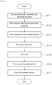
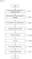
- Fig. 4 is a flowchart showing an example of a method for manufacturing the electrical storage device 10.
- the method for manufacturing the electrical storage device 10 includes, for example, a first step, a second step, a third step, a fourth step, a fifth step, a sixth step and a seventh step.
- the first to seventh steps are carried out by, for example, an apparatus for manufacturing the electrical storage device 10.
- the term "first to seventh steps" refers to conveniently assigned names of the steps, and does not mean the order of the steps.
- Fig. 5 is a diagram related to the first step as step S11.
- the manufacturing apparatus electrically connects the electrode assembly 20 and the electrode terminal 30 through the current collector 22.
- diagrammatic representation of the current collector 22 is omitted for simplification of the drawings.
- the third step as step S13 is carried out after the first step or the second step.
- the manufacturing apparatus heat-seals the opposed heat-sealable resin layers 53 of the exterior film 50 to form a first sealed portion 70, a part of which is an unsealed portion 71A (see Fig. 7 ) (hereinafter, referred to as a "temporary first sealed portion 71").
- the unsealed portion 71A can be formed by using, for example, a seal bar having a shape such that a part of the sealing bar does not come into contact with the exterior film 50.
- the unsealed portion 71A can be formed by interposing a fluororesin film or the like between surfaces (heat-sealable resin layers 53) of the exterior film 50, which face each other.
- the electrode assembly 20 can be held by the exterior film 50, so that the location of the electrode assembly 20 is unlikely to shift with respect to the exterior film 50. This suppresses generation of wrinkles during formation of the second sealed portion 80.
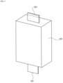
- Fig. 8 is a diagram related to the fourth step as step S14.
- the fourth step is carried out after the third step.
- the manufacturing apparatus fills one space 90 with a resin 100 for forming the lid 60.
- the resin 100 is molten and has predetermined fluidity.
- the resin 100 has, for example, a ring shape with a hole 100X at the center which enables passage of the electrode terminal 30.
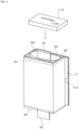
- Fig. 9 is a diagram related to the fifth step as step S15.
- the fifth step is carried out after the fourth step.
- the manufacturing apparatus forms the lid 60 by pressing a mold 110 against the resin 100 filled in one space 90.
- the mold 110 has a size allowing the mold 110 to be housed in the space 90, and has a hole 110X at the center through which the electrode terminal 30 can be inserted.
- the current collector 22 is covered with the lid 60, and the lid 60 and the current collector 22 are joined.
- the sixth step as step S16 is carried out after the fifth step or in parallel to the fifth step.
- the manufacturing apparatus forms the second sealed portion 80 by heat-sealing the exterior film 50 and the seal surface 61 of the lid 60.
- the manufacturing apparatus also carries out the fourth step, the fifth step and the sixth step on the other space 90.
- the seventh step as step S17 is carried out after the fourth step, the fifth step and the sixth step are carried out on two spaces 90.
- the manufacturing apparatus injects an electrolytic solution from the unsealed portion 71A of the temporary first sealed portion 71, evacuates the exterior film 50, and then heat-seals the unsealed portion 71A to form the first sealed portion 70.
- the electrical storage device 10 is an all-solid-state battery, the step of injecting an electrolytic solution in the seventh step is omitted.
- the lid 60 covers at least a part of the current collector 22. Therefore, for example, even if an external force acts on the electrical storage device 10, the current collector 22 is protected by the lid 60.
- An electrical storage device 200 of a second embodiment has the same configuration as in the first embodiment except that a protective material 210 is provided.
- the electrical storage device 200 of the second embodiment will be described mainly for portions different from those in the first embodiment.
- Fig. 10 is a sectional view of the electrical storage device 200.
- the electrical storage device 200 includes a protective material 210 which is disposed between a lid 60 and an electrode assembly 20 and protects a current collector 22.
- the protective material 210 covers at least a part of the current collector 22.
- the protective material 210 is in contact with the covered current collector 22. More preferably, the protective material 210 is joined to the covered current collector 22.
- the protective material 210 covers all current collectors 22, and is joined to the outermost current collector 22.
- the protective material 210 may be disposed so as to fill gaps between a plurality of current collectors 22.
- a portion of the current collector 22 which is welded to an electrode terminal 30, i.e., a welded portion 22X, is covered with the lid 60.
- the lid 60 is joined to the welded portion 22X.
- the protective material 210 can be arbitrarily selected.
- the protective material 210 may be a film or a resin molded product.
- Fig. 11 is a flowchart showing an example of a method for manufacturing the electrical storage device 200.
- the manufacturing method shown in Fig. 11 further includes an eighth step as step S18 in addition to the steps shown in Fig. 4 .
- the manufacturing apparatus disposes the protective material 210 for protecting the current collector 22.
- the eighth step can be carried out at any time after the first step and before the fourth step.
- the protective material 210 covers at least a part of the current collector 22. Therefore, for example, even if an external force acts on the electrical storage device 10, the current collector 22 is protected by the protective material 210.
- the above-described embodiments are an example of possible forms of an electrical storage device, and a method for manufacturing an electrical storage device according to the present invention, and are not intended to limit the forms thereof.
- the electrical storage device, and the method for manufacturing an electrical storage device according to the present invention may have a form different from that exemplified in each of the embodiment.
- An example thereof is a form in which a part of the configuration of any of the embodiments is replaced, changed or omitted, or a form in which a new configuration is added to any of the embodiments.
- two electrode terminals 30 may protrude from one of two lids 60.
- a portion of the outer packaging 40 where the other lid 60 is disposed can be sealed by a known method.
- the other lid 60 may be omitted, and the exterior film 50 may be folded to seal the electrode assembly 20.
- This modification can also be applied to the electrical storage device 200 of the second embodiment.
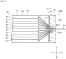
- the configuration of the protective material 210 can be arbitrarily changed.
- the protective material 210 may be a plate which is disposed between the electrode assembly 20 and the welded portion 22X and separates sections inside the outer packaging 40 as shown in Fig. 12 .
- the electrode terminal 30 is only required to enable input and output of electrical power in the electrode assembly 20, and is not required to protrude from the outer packaging 40, for example.
- the electrode terminal 30 may have any shape including a surface that is flush with a surface of the lid 60 which faces the outer portion of the outer packaging 40. This modification can also be applied to the electrical storage device 10 of the second embodiment.
- the fifth step as step S15 shown in Fig. 9 may be omitted.
- the resin 100 has high fluidity, in other words, low viscosity
- the resin 100 spreads so as to fill the space 90 as the space 90 is filled with the resin 100 in the fourth step as step S14. Therefore, when the resin 100 has high fluidity, the fifth step can be omitted.
- This modification can also be applied to the electrical storage device 200 of the second embodiment.
- exterior film 50 may be a laminate (laminate film) including the heat-sealable resin layers 53 on both surfaces of the barrier layer 52.
- first sealed portion 70 may be formed by heat-sealable resin layers 53 laminated on one side or the other side of the barrier layer 52, or may be formed by heat-sealing the heat-sealable resin layer 53 laminated on one side and the heat-sealable resin layer 53 laminated on the other side of the barrier layer 52.
- the root 70X of the first sealed portion 70 is located on an arbitrary surface of the outer packaging 40.
- the root 70X of the first sealed portion 70 is located on a side 43 which is a boundary between the first surface 41 and the second surface 42.
- the heat-sealable resin layer 53 may be joined to, for example, the barrier layer 52 with an adhesive layer 55 interposed therebetween. This modification can also be applied to the electrical storage device 200 of the second embodiment.
Landscapes
- Chemical & Material Sciences (AREA)
- Chemical Kinetics & Catalysis (AREA)
- Electrochemistry (AREA)
- General Chemical & Material Sciences (AREA)
- Engineering & Computer Science (AREA)
- Power Engineering (AREA)
- Microelectronics & Electronic Packaging (AREA)
- Manufacturing & Machinery (AREA)
- Sealing Battery Cases Or Jackets (AREA)
- Connection Of Batteries Or Terminals (AREA)
- Cell Separators (AREA)
- Secondary Cells (AREA)
- Electric Double-Layer Capacitors Or The Like (AREA)
Applications Claiming Priority (2)
| Application Number | Priority Date | Filing Date | Title |
|---|---|---|---|
| JP2022028729 | 2022-02-26 | ||
| PCT/JP2023/007127 WO2023163183A1 (ja) | 2022-02-26 | 2023-02-27 | 蓄電デバイス、蓄電デバイスの製造方法 |
Publications (2)
| Publication Number | Publication Date |
|---|---|
| EP4485673A1 true EP4485673A1 (de) | 2025-01-01 |
| EP4485673A4 EP4485673A4 (de) | 2026-03-11 |
Family
ID=87766255
Family Applications (1)
| Application Number | Title | Priority Date | Filing Date |
|---|---|---|---|
| EP23760181.0A Pending EP4485673A4 (de) | 2022-02-26 | 2023-02-27 | Energiespeichervorrichtung und verfahren zur herstellung der energiespeichervorrichtung |
Country Status (6)
| Country | Link |
|---|---|
| US (1) | US20250141072A1 (de) |
| EP (1) | EP4485673A4 (de) |
| JP (2) | JP7375995B1 (de) |
| KR (1) | KR20240154531A (de) |
| CN (1) | CN118765459A (de) |
| WO (1) | WO2023163183A1 (de) |
Cited By (1)
| Publication number | Priority date | Publication date | Assignee | Title |
|---|---|---|---|---|
| EP4625673A3 (de) * | 2022-08-12 | 2025-12-31 | Dai Nippon Printing Co., Ltd. | Energiespeichervorrichtung, verstärkungskomponente und verfahren zur herstellung der energiespeichervorrichtung |
Families Citing this family (3)
| Publication number | Priority date | Publication date | Assignee | Title |
|---|---|---|---|---|
| WO2025115974A1 (ja) * | 2023-11-30 | 2025-06-05 | 大日本印刷株式会社 | 外装フィルム、蓄電デバイス、蓄電デバイスの製造方法 |
| JP7835235B2 (ja) * | 2024-02-29 | 2026-03-25 | 大日本印刷株式会社 | 蓄電デバイス、電動自動車、蓄電デバイス用包装材、蓄電デバイス用容器及びその製造方法 |
| KR20260020788A (ko) * | 2024-08-05 | 2026-02-12 | 주식회사 엘지에너지솔루션 | 이차 전지 및 이를 포함하는 배터리 팩 |
Family Cites Families (7)
| Publication number | Priority date | Publication date | Assignee | Title |
|---|---|---|---|---|
| JPS5934992Y2 (ja) * | 1979-03-28 | 1984-09-27 | 松下電器産業株式会社 | 電気二重層キャパシタ |
| JP4424053B2 (ja) * | 2004-04-28 | 2010-03-03 | トヨタ自動車株式会社 | ラミネート型二次電池、およびその組電池 |
| JP2014041724A (ja) * | 2012-08-21 | 2014-03-06 | Toyota Industries Corp | 蓄電装置、及び電極組立体の製造方法 |
| JP6772855B2 (ja) * | 2017-01-20 | 2020-10-21 | トヨタ自動車株式会社 | 全固体電池 |
| JP6879230B2 (ja) | 2018-03-05 | 2021-06-02 | トヨタ自動車株式会社 | 全固体電池 |
| KR102809759B1 (ko) * | 2019-10-14 | 2025-05-16 | 주식회사 엘지에너지솔루션 | 배터리 셀, 이러한 배터리 셀을 포함하는 배터리 모듈 및 이러한 배터리 모듈을 포함하는 배터리 팩 |
| KR20250116793A (ko) * | 2020-02-07 | 2025-08-01 | 다이니폰 인사츠 가부시키가이샤 | 축전 디바이스 |
-
2023
- 2023-02-27 WO PCT/JP2023/007127 patent/WO2023163183A1/ja not_active Ceased
- 2023-02-27 EP EP23760181.0A patent/EP4485673A4/de active Pending
- 2023-02-27 US US18/837,290 patent/US20250141072A1/en active Pending
- 2023-02-27 JP JP2023552206A patent/JP7375995B1/ja active Active
- 2023-02-27 KR KR1020247025218A patent/KR20240154531A/ko active Pending
- 2023-02-27 CN CN202380023647.3A patent/CN118765459A/zh active Pending
- 2023-10-13 JP JP2023177173A patent/JP2024009956A/ja active Pending
Cited By (2)
| Publication number | Priority date | Publication date | Assignee | Title |
|---|---|---|---|---|
| EP4625673A3 (de) * | 2022-08-12 | 2025-12-31 | Dai Nippon Printing Co., Ltd. | Energiespeichervorrichtung, verstärkungskomponente und verfahren zur herstellung der energiespeichervorrichtung |
| EP4625674A3 (de) * | 2022-08-12 | 2026-01-07 | Dai Nippon Printing Co., Ltd. | Energiespeichervorrichtung, verstärkungskomponente und verfahren zur herstellung der energiespeichervorrichtung |
Also Published As
| Publication number | Publication date |
|---|---|
| EP4485673A4 (de) | 2026-03-11 |
| JPWO2023163183A1 (de) | 2023-08-31 |
| CN118765459A (zh) | 2024-10-11 |
| JP7375995B1 (ja) | 2023-11-08 |
| KR20240154531A (ko) | 2024-10-25 |
| US20250141072A1 (en) | 2025-05-01 |
| JP2024009956A (ja) | 2024-01-23 |
| WO2023163183A1 (ja) | 2023-08-31 |
Similar Documents
| Publication | Publication Date | Title |
|---|---|---|
| EP4485673A1 (de) | Energiespeichervorrichtung und verfahren zur herstellung der energiespeichervorrichtung | |
| EP4456277A1 (de) | Deckel, stromspeichervorrichtung und verfahren zur herstellung einer stromspeichervorrichtung | |
| CN115066791A (zh) | 蓄电器件和蓄电器件的制造方法 | |
| US20250055098A1 (en) | Power storage device, lid, and power storage device manufacturing method | |
| EP4571991A1 (de) | Energiespeichervorrichtung, verstärkungskomponente und verfahren zur herstellung der energiespeichervorrichtung | |
| EP4679580A1 (de) | Energiespeichervorrichtung, deckelkörper und deckeleinheit | |
| EP4485644A1 (de) | Deckelkörper, deckelkörpereinheit, stromspeichervorrichtung, verfahren zur herstellung einer deckelkörpereinheit und verfahren zur herstellung einer stromspeichervorrichtung | |
| US20250079588A1 (en) | Power storage device | |
| JP7643651B1 (ja) | 蓋体、蓋本体、蓄電デバイス | |
| JP7643652B1 (ja) | 蓋体、蓄電デバイス | |
| EP4693709A1 (de) | Energiespeichervorrichtung, elektrodenanschlusseinheit und aussenkörpersatz | |
| JP7726412B2 (ja) | 蓄電デバイス及び蓄電デバイス用の保護部材 | |
| JP7786654B2 (ja) | 蓄電デバイス、外装フィルム、外装体キット、蓄電デバイスの製造方法 | |
| WO2025084359A1 (ja) | 蓄電デバイス用外装フィルム及び蓄電デバイス | |
| EP4693642A1 (de) | Energiespeichervorrichtung und verfahren zur herstellung davon | |
| EP4693630A1 (de) | Stromspeichervorrichtung, fixiervorrichtung und verfahren zur herstellung der stromspeichervorrichtung | |
| KR20250160887A (ko) | 축전 디바이스의 제조 방법, 및 축전 디바이스 |
Legal Events
| Date | Code | Title | Description |
|---|---|---|---|
| STAA | Information on the status of an ep patent application or granted ep patent |
Free format text: STATUS: THE INTERNATIONAL PUBLICATION HAS BEEN MADE |
|
| PUAI | Public reference made under article 153(3) epc to a published international application that has entered the european phase |
Free format text: ORIGINAL CODE: 0009012 |
|
| STAA | Information on the status of an ep patent application or granted ep patent |
Free format text: STATUS: REQUEST FOR EXAMINATION WAS MADE |
|
| 17P | Request for examination filed |
Effective date: 20240905 |
|
| AK | Designated contracting states |
Kind code of ref document: A1 Designated state(s): AL AT BE BG CH CY CZ DE DK EE ES FI FR GB GR HR HU IE IS IT LI LT LU LV MC ME MK MT NL NO PL PT RO RS SE SI SK SM TR |
|
| DAV | Request for validation of the european patent (deleted) | ||
| DAX | Request for extension of the european patent (deleted) | ||
| A4 | Supplementary search report drawn up and despatched |
Effective date: 20260209 |
|
| RIC1 | Information provided on ipc code assigned before grant |
Ipc: H01M 50/531 20210101AFI20260203BHEP Ipc: H01G 11/80 20130101ALI20260203BHEP Ipc: H01G 11/84 20130101ALI20260203BHEP Ipc: H01M 50/103 20210101ALI20260203BHEP Ipc: H01M 50/105 20210101ALI20260203BHEP Ipc: H01M 50/129 20210101ALI20260203BHEP Ipc: H01M 50/15 20210101ALI20260203BHEP Ipc: H01M 50/16 20210101ALI20260203BHEP Ipc: H01M 50/164 20210101ALI20260203BHEP Ipc: H01M 50/166 20210101ALI20260203BHEP Ipc: H01M 50/169 20210101ALI20260203BHEP Ipc: H01M 50/176 20210101ALI20260203BHEP Ipc: H01M 50/178 20210101ALI20260203BHEP Ipc: H01M 50/54 20210101ALI20260203BHEP Ipc: H01M 50/548 20210101ALI20260203BHEP |