EP4485597A2 - Verfahren zur zellwicklung und system zur zellwicklung - Google Patents
Verfahren zur zellwicklung und system zur zellwicklung Download PDFInfo
- Publication number
- EP4485597A2 EP4485597A2 EP24185411.6A EP24185411A EP4485597A2 EP 4485597 A2 EP4485597 A2 EP 4485597A2 EP 24185411 A EP24185411 A EP 24185411A EP 4485597 A2 EP4485597 A2 EP 4485597A2
- Authority
- EP
- European Patent Office
- Prior art keywords
- cathode
- winding
- cathode electrode
- embossing
- experimental
- Prior art date
- Legal status (The legal status is an assumption and is not a legal conclusion. Google has not performed a legal analysis and makes no representation as to the accuracy of the status listed.)
- Pending
Links
Images


Classifications
-
- H—ELECTRICITY
- H01—ELECTRIC ELEMENTS
- H01M—PROCESSES OR MEANS, e.g. BATTERIES, FOR THE DIRECT CONVERSION OF CHEMICAL ENERGY INTO ELECTRICAL ENERGY
- H01M10/00—Secondary cells; Manufacture thereof
- H01M10/04—Construction or manufacture in general
- H01M10/0404—Machines for assembling batteries
- H01M10/0409—Machines for assembling batteries for cells with wound electrodes
-
- H—ELECTRICITY
- H01—ELECTRIC ELEMENTS
- H01M—PROCESSES OR MEANS, e.g. BATTERIES, FOR THE DIRECT CONVERSION OF CHEMICAL ENERGY INTO ELECTRICAL ENERGY
- H01M10/00—Secondary cells; Manufacture thereof
- H01M10/04—Construction or manufacture in general
- H01M10/0431—Cells with wound or folded electrodes
-
- H—ELECTRICITY
- H01—ELECTRIC ELEMENTS
- H01M—PROCESSES OR MEANS, e.g. BATTERIES, FOR THE DIRECT CONVERSION OF CHEMICAL ENERGY INTO ELECTRICAL ENERGY
- H01M10/00—Secondary cells; Manufacture thereof
- H01M10/05—Accumulators with non-aqueous electrolyte
- H01M10/058—Construction or manufacture
- H01M10/0587—Construction or manufacture of accumulators having only wound construction elements, i.e. wound positive electrodes, wound negative electrodes and wound separators
-
- H—ELECTRICITY
- H01—ELECTRIC ELEMENTS
- H01M—PROCESSES OR MEANS, e.g. BATTERIES, FOR THE DIRECT CONVERSION OF CHEMICAL ENERGY INTO ELECTRICAL ENERGY
- H01M4/00—Electrodes
- H01M4/02—Electrodes composed of, or comprising, active material
- H01M4/04—Processes of manufacture in general
- H01M4/043—Processes of manufacture in general involving compressing or compaction
- H01M4/0435—Rolling or calendering
-
- H—ELECTRICITY
- H01—ELECTRIC ELEMENTS
- H01M—PROCESSES OR MEANS, e.g. BATTERIES, FOR THE DIRECT CONVERSION OF CHEMICAL ENERGY INTO ELECTRICAL ENERGY
- H01M6/00—Primary cells; Manufacture thereof
- H01M6/005—Devices for making primary cells
-
- H—ELECTRICITY
- H01—ELECTRIC ELEMENTS
- H01M—PROCESSES OR MEANS, e.g. BATTERIES, FOR THE DIRECT CONVERSION OF CHEMICAL ENERGY INTO ELECTRICAL ENERGY
- H01M4/00—Electrodes
- H01M4/02—Electrodes composed of, or comprising, active material
- H01M2004/026—Electrodes composed of, or comprising, active material characterised by the polarity
- H01M2004/028—Positive electrodes
-
- Y—GENERAL TAGGING OF NEW TECHNOLOGICAL DEVELOPMENTS; GENERAL TAGGING OF CROSS-SECTIONAL TECHNOLOGIES SPANNING OVER SEVERAL SECTIONS OF THE IPC; TECHNICAL SUBJECTS COVERED BY FORMER USPC CROSS-REFERENCE ART COLLECTIONS [XRACs] AND DIGESTS
- Y02—TECHNOLOGIES OR APPLICATIONS FOR MITIGATION OR ADAPTATION AGAINST CLIMATE CHANGE
- Y02E—REDUCTION OF GREENHOUSE GAS [GHG] EMISSIONS, RELATED TO ENERGY GENERATION, TRANSMISSION OR DISTRIBUTION
- Y02E60/00—Enabling technologies; Technologies with a potential or indirect contribution to GHG emissions mitigation
- Y02E60/10—Energy storage using batteries
-
- Y—GENERAL TAGGING OF NEW TECHNOLOGICAL DEVELOPMENTS; GENERAL TAGGING OF CROSS-SECTIONAL TECHNOLOGIES SPANNING OVER SEVERAL SECTIONS OF THE IPC; TECHNICAL SUBJECTS COVERED BY FORMER USPC CROSS-REFERENCE ART COLLECTIONS [XRACs] AND DIGESTS
- Y02—TECHNOLOGIES OR APPLICATIONS FOR MITIGATION OR ADAPTATION AGAINST CLIMATE CHANGE
- Y02P—CLIMATE CHANGE MITIGATION TECHNOLOGIES IN THE PRODUCTION OR PROCESSING OF GOODS
- Y02P70/00—Climate change mitigation technologies in the production process for final industrial or consumer products
- Y02P70/50—Manufacturing or production processes characterised by the final manufactured product
Definitions
- the disclosure relates to the field of cell winding technologies, and in particular, to a method for cell winding and a system for cell winding.
- An alignment of tabs of a cell may impact the electrical performance of a finished battery.
- a misalignment amount of the cathode tabs is typically controlled in a process and serves as an indicator of tab misalignment.
- the tab misalignment of the cell may still occur with an increase in the number of winding circles, resulting in an adverse effect on a yield of the cell.
- the tab misalignment can be reduced by obtaining and calculating tab misalignments in previous windings of multiple cells and then adjusting and fixing relevant parameters of embossing processing.
- obtaining and calculating the tab misalignments in previous windings of multiple cells requires processing of a large amount of data.
- positions of thick portions and thin portions of a feeding electrode are uncertain, only adjusting the relevant parameters of the embossing processing by analyzing previous data to reduce the tab misalignment may easily cause the thick portions of the electrode to be thicker and the thin portions of the electrode to be thinner, which may increase the misalignment amount of tabs after cell winding, resulting in a decrease in a winding yield of the cell.
- the disclosure provides a method for cell winding.
- the method includes feeding materials, preparing winding, embossing, and winding.
- the feeding materials includes obtaining a separator, a cathode electrode, and an anode electrode.
- the cathode electrode satisfies that: after pre-winding, a first cathode tab of the cathode electrode and a second cathode tab of the cathode electrode adjacent to the first cathode tab, adjacent to a winding end of the cathode electrode, are arranged with a surplus misalignment.
- the preparing winding includes fixing a starting end of the separator, a starting end of the cathode electrode, and a starting end of the anode electrode to a winding device.
- the embossing includes embossing the cathode electrode by a rolling device, such that the cathode electrode subjected to embossing satisfies that: the first cathode tab is aligned with the second cathode tab after winding.
- an embossing depth required by the cathode electrode is calculated based on the surplus misalignment formed by the pre-winding, to enable the first cathode tab and the second cathode tab, that are adjacent to the winding end of the cathode electrode, to be aligned with each other after the winding.
- the winding includes winding the separator, the cathode electrode, and the anode electrode by the winding device to form a cell.
- a system for cell winding includes a feeding device, a rolling device, and a winding device.
- the feeding device is configured to provide a separator, a cathode electrode, and an anode electrode.
- the cathode electrode satisfies that: after pre-winding, a first cathode tab of the cathode electrode and a second cathode tab of the cathode electrode adjacent to the first cathode tab, adjacent to a winding end of the cathode electrode, are arranged with a surplus misalignment.
- the rolling device is configured to emboss the cathode electrode, such that the cathode electrode subjected to embossing satisfies that: the first cathode tab is aligned with the second cathode tab after winding.
- the winding device is configured to fix a starting end of the separator, a starting end of the cathode electrode, and a starting end of the anode electrode, and to wind the separator, the cathode electrode, and the anode electrode.
- a method for cell winding includes pre-winding, feeding materials, preparing winding, embossing, and winding.
- the pre-winding includes obtaining and pre-winding an experimental separator, an experimental cathode electrode, and an experimental anode electrode; where after the pre-winding is completed, each two adjacent cathode tabs on the experimental cathode electrode are arranged with a surplus misalignment.
- the feeding materials includes obtaining a production separator, a production cathode electrode, and a production anode electrode; where the production cathode electrode obtained satisfies that a distance between each two cathode tabs on the production cathode electrode is equal to a distance between the each two cathode tabs on the experimental cathode electrode.
- the preparing winding includes fixing a starting end of the production separator, a starting end of the production cathode electrode, and a starting end of the production anode electrode to a winding device.
- the embossing includes embossing the production cathode electrode by a rolling device to enable the production cathode electrode subjected to embossing to satisfy that: cathode tabs on the production cathode electrode are aligned with each other after winding; where during the embossing, an embossing depth required by the production cathode electrode is calculated based on the surplus misalignment between the each two adjacent cathode tabs on the experimental cathode electrode after the pre-winding, to enable the each two adjacent cathode tabs on the production cathode electrode to be aligned with each other after the winding.
- the winding includes winding the production separator, the production cathode electrode, and the production anode electrode by the winding device to form a cell.
- a system for cell winding includes a pre-winding device, a feeding device, a rolling device, and a winding device.
- the pre-winding device is configured to obtain an experimental separator, an experimental cathode electrode, and an experimental anode electrode and to complete a pre-winding, where after the pre-winding is completed, each two adjacent cathode tabs on the experimental cathode electrode are arranged with a surplus misalignment;
- the feeding device is configured to provide a production separator, a production cathode electrode, and a production anode electrode, where the production cathode electrode provided satisfies that: a distance between each two adjacent cathode tabs on the production cathode electrode is equal to a distance between the each two adjacent cathode tabs on the experimental cathode electrode;
- the rolling device is configured to emboss the production cathode electrode to enable the production cathode electrode subjected to embossing to satisfy that: cathode tabs on the production cathode electrode are aligned with each other after winding.
- the winding device is configured to fix a starting end of the production separator, a starting end of the production cathode electrode, and a starting end of the production anode electrode and to wind the production separator, the production cathode electrode, and the production anode electrode.
- misalignment parameters of tabs during winding of previously wound cells are obtained and used for controlling of a variation in embossing pressure to adjust a thickness of an electrode, thereby reducing a misalignment amount of tabs during a current winding and improving a yield of a cell.
- obtaining the misalignment parameters of tabs during winding of previously wound cells requires obtaining of a large amount of relevant data of the previously wound cells, making a process of cell winding more cumbersome.
- the disclosure provides a method for cell winding and a system for cell winding to reduce the misalignment amount of tabs, thereby improving the yield of the cell.
- FIG. 1 is a schematic flow chart of a method for cell winding according to an embodiment of the disclosure
- FIG. 2 is a schematic diagram of a system for cell winding according to an embodiment of the disclosure
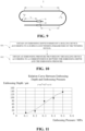
- FIG. 3 is a schematic diagram of a wound cell according to an embodiment of the disclosure
- FIG. 4 is a schematic diagram of a cathode electrode in an unwinding state according to an embodiment of the disclosure.
- a method for cell winding is provided in an embodiment of the disclosure to reduce a misalignment amount of tabs.
- the method for cell winding includes the following.
- feeding materials is carried out to obtain a separator 1, a cathode electrode 3, and an anode electrode 5.
- the cathode electrode 3 obtained in the feeding materials is configured such that after pre-winding of a cell 10, a first cathode tab 31 of the of the cathode electrode 3 and a second cathode tab 32 of the cathode electrode 3 adjacent to the first cathode tab 31, adjacent to a winding end of the cathode electrode 3, are arranged with a surplus misalignment.
- preparing winding is carried out to fix a starting end of the separator 1, a starting end of the cathode electrode 3, and a starting end of the anode electrode 5 to a winding device 40.
- embossing is carried out to emboss the cathode electrode 3 by a rolling device 60, and the cathode electrode 3 subjected to the embossing is configured such that the first cathode tab 31 is aligned with the second cathode tab 32 after winding of the cell 10.
- the embossing is configured to enable the surplus misalignment between the first cathode tab 31 and the second cathode tab 32 adjacent to the first cathode tab 31 after the winding to be zero, where the first cathode tab 31 and the second cathode tab 32 are arranged adjacent to the winding end of the cathode electrode 3.
- the winding is carried out to wind the separator 1, the cathode electrode 3, and the anode electrode 5 by the winding device 40 to form the cell 10.
- the winding end of the cathode electrode 3 refers to a terminal end of the cathode electrode 3 where winding starts.
- the pre-winding of the cell 10 is a winding of the cathode electrode 3 without embossing.
- a purpose of the pre-winding is to facilitate measurement and calculation of relevant parameters of the surplus misalignment between the first cathode tab 31 and the second cathode tab 32.
- the embossing of the rolling device 60 refers to a process where pressure is applied to the product, causing it to deform in the thickness direction. Consequently, this results in an increase in the overall thickness of the product in the thickness direction.
- the cathode electrode 3 is configured such that, after the pre-winding of the cell 10, the first cathode tab 31 of the cathode electrode 3 and the second cathode tab 32 of the cathode electrode 3 adjacent to the first cathode tab 31, adjacent to the winding end of the cathode electrode 3, are arranged to form the surplus misalignment. That is, a distance between the first cathode tab 31 and the second cathode tab 32 on the cathode electrode 3 in the unwinding state is increased in advance. Then, during the embossing, the embossing is performed on the cathode electrode 3 to thicken the cathode electrode 3.
- the first cathode tab 31 and the second cathode tab 32 which are originally in surplus misalignment can be aligned. Furthermore, by fixing rolling parameters of the rolling device 60, an overall thickness of the cathode electrode 3 can be made more uniform, so that tabs on the cathode electrode 3, other than the first cathode tab 31 and the second cathode tab 32, can be aligned with each other. Thus, according to the method for cell winding provided by this embodiment, the misalignment amount of tabs can be reduced, thereby improving a winding yield of the cell 10.
- the separator 1 provided in this embodiment includes a first separator 11 and a second separator 12. Before winding of an electrode of the cell 10, the first separator 11, the cathode electrode 3, the second separator 12, and the anode electrode 5 are sequentially stacked. After the winding of the electrode of the cell 10, the first separator 11, the cathode electrode 3, the second separator 12, and the anode electrode 5 are sequentially stacked from inside to outside.
- the system for cell winding 100 includes a feeding device 20, a winding device 40, and a rolling device 60.
- the feeding device 20 is configured to provide the separator 1, the cathode electrode 3, and the anode electrode 5.
- the cathode electrode 3 provided by the feeding device 20 is configured such that, after the pre-winding, the first cathode tab 31 and the second cathode tab 32 adjacent to the first cathode tab 31, adjacent to the winding end of the cathode electrode 3, are arranged with the surplus misalignment.
- the rolling device 60 is configured to emboss the cathode electrode 3, such that the cathode electrode 3 subjected to the embossing is configured such that the first cathode tab 31 is aligned with the second cathode tab 32 after the winding of the cell 10.
- the winding device 40 is configured to fix the starting end of the separator 1, the starting end of the cathode electrode 3, and the starting end of the anode electrode 5, and to wind the separator 1, the cathode electrode 3, and the anode electrode 5.
- the cathode electrode 3 provided by the feeding device 20 is designed and configured such that, after the pre-winding, the first cathode tab 31 of the cathode electrode 3 and the second cathode tab 32 of the cathode electrode 3 adjacent to the first cathode tab 31, adjacent to the winding end of the cathode electrode 3, are arranged with the surplus misalignment. That is, the distance between the first cathode tab 31 and the second cathode tab 32 on the cathode electrode 3 in the unwinding state is increased in advance.
- the starting end of the separator 1, the starting end of the cathode electrode 3, and the starting end of the anode electrode 5 provided by the feeding device 20 are fixed by the winding device 40, and the cathode electrode 3 is embossed by the rolling device 60 to thicken the cathode electrode 3.
- the separator 1, the cathode electrode 3, and the anode electrode 5 are wound by the winding device 40. After the winding, since the cathode electrode 3 is thickened, the first cathode tab 31 and the second cathode tab 32 which are originally in surplus misalignment can be aligned with each other.
- an overall thickness of the cathode electrode 3 can be made more uniform, so that other taps on the cathode electrode 3, other than the first cathode tab 31 and the second cathode tab 32, can be aligned with each other.
- the misalignment amount of tabs can be reduced, thereby improving the winding yield of the cell.
- FIG. 5 is a schematic diagram of the rolling device according to an embodiment of the disclosure.
- the rolling device 60 includes a support 61, a first compression roller 62, a first driver 63, a second compression roller 64, a second driver 65, and a control valve 66.
- the first compression roller 62 is rotatably disposed on the support 61.
- the first driver 63 is configured to rotate the first compression roller 62.
- the second compression roller 64 is rotatably disposed on the support 61.
- the second compression roller 64 is parallel to the first compression roller 62.
- the second driver 65 is configured to drive the first compression roller 62 to move toward or away from the second compression roller 64 to adjust an embossing pressure of the rolling device 60.
- the control valve 66 is electrically connected to the second driver 65 and configured to control the second driver 65 to drive the first compression roller 62 to move towards or away from the second compression roller 64.
- the second driver 65 is controlled to move or be fixed by adjusting the control valve 66, thereby driving the first compression roller 62 to move towards/away from the second compression roller 64 or to be relatively fixed. It is convenient to adjust or fix the embossing pressure applied by the rolling device 60 to the cathode electrode 3, such that the rolling device 60 can be applied to cathode electrodes 3 requiring different embossing depths.
- the first compression roller 62 is a rubber-coating roller
- the first driver 63 is a motor
- the second compression roller 64 is an embossing roller
- the second driver 65 is a cylinder
- the control valve 66 is a proportional valve.
- the first compression roller 62 satisfies that: the first compression roller 62 rotates actively; the first compression roller 62 is made of a common aluminum roller and polyurethane; and the first compression roller 62 has a hardness of 35 HS, a diameter of 29.6 mm, and a length of 213 mm.
- the second compression roller 64 satisfies that: the second compression roller 64 rotates passively; the second compression roller 64 is made of a high-strength aluminum alloy; the second compression roller 64 had a hardness of 500 HV, a diameter of 29.6 mm, and a length of 213 mm; each of convex points on the second compression roller 64 is circular; a radius of the convex point on the second compression roller 64 is 3.6 mm; and a distance between centers of two adjacent convex points on the second compression roller 64 is 3.5 mm; a height of the convex point on the second compression roller 64 is 0.8 mm; and a parallelism between the second compression roller 64 and the first compression roller 62 is 0.03 mm.
- control valve 66 is configured to control a proportional electromagnet by outputting current in proportion to pulses, the proportional electromagnet is configured to proportionally control a position of a valve core to achieve rapid pressure rise and fall adjustment, and a control precision of the control valve 66 is limited to or equal to ⁇ 0.002 Mpa.
- first driver 63 and the second driver 65 may be other driving structures
- first compression roller 62 and the second compression roller 64 may be other roller structures
- control valve 66 may be other control devices, which is not limited in the disclosure.
- FIG. 6 is a schematic flow chart of a method for cell winding according to another embodiment of the disclosure.
- a method for cell winding is provided in an embodiment of the disclosure to reduce a misalignment amount of tabs.
- the method for cell winding includes the following.
- feeding materials is carried out to obtain the separator 1, the cathode electrode 3, and the anode electrode 5.
- the cathode electrode 3 obtained in the feeding materials is configured such that after the pre-winding of the cell 10, the first cathode tab 31 of the cathode electrode 3 and the second cathode tab 32 of the cathode electrode 3 adjacent to the first cathode tab 31, adjacent to the winding end of the cathode electrode 3, are arranged with the surplus misalignment.
- preparing winding is carried out to fix the starting end of the separator 1, the starting end of the cathode electrode 3, and the starting end of the anode electrode 5 to the winding device 40.
- embossing is carried out to emboss the separator 1 and the cathode electrode 3 by the rolling device 60, and the cathode electrode 3 subjected to the embossing is configured such that the first cathode tab 31 is aligned with the second cathode tab 32 after the winding of the cell 10.
- winding is carried out to wind the separator 1, the cathode electrode 3, and the anode electrode 5 by the winding device 40 to form the cell 10.
- the cathode electrode 3 is configured such that, after the pre-winding of the cell 10, the first cathode tab 31 of the cathode electrode 3 and the second cathode tab 32 of the cathode electrode 3 adjacent to the first cathode tab 31, adjacent to the winding end of the cathode electrode 3, are arranged to form the surplus misalignment. That is, the distance between the first cathode tab 31 and the second cathode tab 32 on the cathode electrode 3 in the unwinding state is increased in advance.
- the embossing is performed on the separator 1 and the cathode electrode 3 to thicken the separator 1 and the cathode electrode 3.
- the separator 1 and the cathode electrode 3 thicken, such that the first cathode tab 31 and the second cathode tab 32 which are originally in surplus misalignment can be aligned with each other.
- an overall thickness of the separator 1 and an overall thickness of the cathode electrode 3 can be made more uniform, so that the tabs on the cathode electrode 3, other than the first cathode tab 31 and the second cathode tab 32, can be aligned.
- the misalignment amount of tabs can be reduced, thereby improving the winding yield of the cell 10.
- the embossing is carried out to emboss the first separator 11 and the cathode electrode 3 to thicken the first separator 11 and the cathode electrode 3.
- the embossing is carried out to emboss the second separator 12 and the cathode electrode 3 to thicken the second separator 12 and the cathode electrode 3.
- the embossing is carried out to emboss the first separator 11, the second separator 12, and the cathode electrode 3 to thicken the first separator 11, the second separator 12, and the cathode electrode 3.
- the embossing in the method for cell winding is carried out to emboss the separator 1, the cathode electrode 3, and the anode electrode 5 by the rolling device 60, and the cathode electrode 3 subjected to the embossing is configured such that the first cathode tab 31 is aligned with the second cathode tab 32 after the winding of the cell 10.
- FIG. 7 is a schematic diagram illustrating winding of the cathode electrode in a desired state according to an embodiment of the disclosure
- FIG. 8 is a schematic diagram illustrating winding of the cathode electrode with a surplus misalignment according to an embodiment of the disclosure
- FIG. 9 is a schematic diagram illustrating winding of the cathode electrode subjected to embossing according to an embodiment of the disclosure.
- the surplus misalignment between the first cathode tab 31 and the second cathode tab 32 satisfies that: after the pre-winding of the cathode electrode 3, the first cathode tab 31 is positioned in a first circle of the cathode electrode 3 subjected to the pre-winding, and the second cathode tab 32 is positioned in a second circle of the cathode electrode 3 subjected to the pre-winding. There is a surplus ⁇ L between the second cathode tab 32 and the first cathode tab 31.
- the surplus ⁇ L is a distance from a geometric center of the first cathode tab 31 to a geometric center of the second cathode tab 32 along a winding trajectory of the cathode electrode 3.
- the winding trajectory refers to a trajectory along which the cathode electrode 3 is wound.
- the first cathode tab 31 and the second cathode tab 32 of the cathode electrode 3 are configured such that, after the pre-winding of the cathode electrode 3, the first cathode tab 31 is positioned in the first circle of the wound cathode electrode 3, and the second cathode tab 32 is positioned in the second circle of the wound cathode electrode 3.
- the second cathode tab 32 exceeds the first cathode tab 31, that is, there is the surplus ⁇ L between the second cathode tab 32 and the first cathode tab 31.
- the thickness of the cathode electrode 3 in the unwinding state may be further increased by the rolling device 60, so that the first cathode tab 31 and the second cathode tab 32 which are originally in surplus misalignment can be aligned with each other after the winding of the cathode electrode 3, thereby allowing the surplus ⁇ L to be changed from non-zero to zero after the winding of the cathode electrode 3.
- FIG. 10 is a flow chart of determining the embossing pressure according to an embodiment of the disclosure
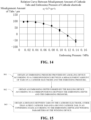
- FIG. 11 is a graph illustrating a correspondence between the embossing depth and the embossing pressure according to an embodiment of the disclosure.
- the embossing depth y formed by the rolling device 60 is obtained according to the surplus ⁇ L and the winding parameters of the winding device 40.
- the embossing pressure x provided by the rolling device 60 is obtained according to a correspondence between the embossing depth y and the embossing pressure x.
- the surplus ⁇ L is designed to be a fixed value.
- a specific value of the surplus ⁇ L illustrated in FIG. 8 may be obtained by measuring the cell 10 after the pre-winding. Since the winding device 40 is fixed, the winding parameters of the winding device 40 are also fixed values. As illustrated in FIGS. 7 and 8 , the winding parameters of the winding device 40 include L 1 , L 2 , L 3 , R 1 , and R 2 .
- L 1 represents a distance from one end of the first cathode tab 31 adjacent to a first winding bend to the first winding bend
- L 3 represents a distance from a second winding bend to one end of the second cathode tab 32 adjacent to the second winding bend
- L 2 represents a distance from the first winding bend to the second winding bend
- R 1 represents a radius of the first winding bend
- R 2 represents a radius of the second winding bend.
- the embossing depth is set to be represented as y
- the embossing pressure is set to be represented as x
- the embossing depth y required to be formed on the cathode electrode 3 by the rolling device 60 can be obtained. That is, an increase in the thickness of the cathode electrode 3, that is required through the embossing, can be obtained.
- the thickness of the cathode electrode 3 can be increased under the action of the rolling device 60, and a winding thickness can be uniform, where the winding thickness is the sum of a thickness of the cathode electrode 3 at a fixed position and the embossing depth y at the fixed position.
- the thickness of the cathode electrode 3 can be increased, so that the first cathode tab 31 can be aligned with the second cathode tab 32 after the winding of the cathode electrode 3.
- the fixed embossing pressure x provided by the rolling device 60 can make the winding thickness of the cathode electrode 3 more uniform, so that the tabs on the cathode electrode 3, other than the first cathode tab 31 and the second cathode tab 32, can also be aligned, which is beneficial to reducing the misalignment amount of the tabs on the cathode electrode 3, thereby improving the winding yield of the cell 10.
- FIG. 12 is a schematic flow chart of determining a distance between the tabs on the cathode electrode, other than the first cathode tab and the second cathode tab, according to an embodiment of the disclosure.
- the embossing depth y formed by the rolling device 60 is obtained according to the surplus ⁇ L and the winding parameters of the winding device 40.
- the distance between the tabs on the cathode electrode 3, other than the first cathode tab 31 and the second cathode tab 32, in an unwinding state of the cathode electrode 3 is obtained according to the embossing depth y and the winding parameters of the winding device 40.
- winding parameters of the first separator 11, the cathode electrode 3, the second separator 12, and the anode electrode 5 may be obtained according to a structure and a winding form of the second circle of the cell 10. Then, the distance between the tabs of the cathode electrode 3, other than the first cathode tab 31 and the second cathode tab 32, in the unwinding state can be obtained according to the embossment depth y and the winding parameters L 1 , L 2 , L 3 , R 1 , and R 2 of the winding device 40.
- the embossing depth y required to be formed on the cathode electrode 3 by the rolling device 60 can be obtained. That is, an increase in the thickness of the cathode electrode 3, that is required through the embossing, can be obtained.
- the distance between the tabs on the cathode electrode 3, other than the first cathode tab 31 and the second cathode tab 32, in the unwinding state of the cathode electrode 3 can be obtained, so that the cathode electrode 3 can be configured such that, after the winding, the tabs on the cathode electrode 3, other than the first cathode tab 31 and the second cathode tab 32, can be aligned.
- the tabs on the cathode electrode 3 can be aligned after the winding of the cathode electrode 3, thereby improving the winding yield of the cell 10.
- FIG. 13 is a schematic flow chart of determining the distance between the first cathode tab and the second cathode tab on the cathode electrode according to another embodiment of the disclosure
- FIG. 14 is a graph illustrating the correspondence between the misalignment amount of cathode tabs and the embossing pressure according to an embodiment of the disclosure.
- the embossing pressure x provided by the rolling device 60 is obtained according to a correspondence between the misalignment amount z 1 of the cathode tabs on the cathode electrode 3 and the embossing pressure x.
- the embossing depth y formed by the rolling device 60 is obtained according to the correspondence between the embossing depth y and the embossing pressure x.
- a value of the surplus ⁇ L is obtained according to the embossing depth y and the winding parameters L 1 , L 2 , L 3 , R 1 , and R 2 of the winding device 40, to obtain the distance between the first cathode tab 31 and the second cathode tab 32 in the unwinding state of the cathode electrode.
- the misalignment amount of the tabs on the cathode electrode 3 is set to be represented as z 1
- the embossing pressure is set to be represented as x
- z 1 f x 2 + g x + h and the minimum value (i.e., zero) of the misalignment amount z 1 of the tabs on the cathode electrode 3, a determined value of the embossing pressure x, that is required to be provided by the rolling device 60, can be obtained.
- the misalignment amount is obtained by measuring a maximum distance between tabs on a previous cathode electrode along a winding trajectory after winding of the previous cathode electrode, where the previous cathode electrode is the same as the cathode electrode 3 except that there is no surplus misalignment provided for the previous cathode electrode.
- the embossing depth is set to be represented as y
- the embossing pressure is set to be represented as x
- the winding parameters L 1 , L 2 , L 3 , R 1 , and R 2 of the winding device 40 are also fixed values.
- the winding parameters of the winding device 40 include L 1 , L 2 , L 3 , R 1 , and R 2 .
- L 1 represents a distance from one end of the first cathode tab 31 adjacent to a first winding bend to the first winding bend
- L 3 represents a distance from a second winding bend to one end of the second cathode tab 32 adjacent to the second winding bend
- L 2 represents a distance from the first winding bend to the second winding bend
- R 1 represents a radius of the first winding bend
- R 2 represents a radius of the second winding bend.
- the method for cell winding provided in the embodiments of the disclosure, first, through data fitting analysis of the misalignment amount z 1 of the tabs on the cathode electrode 3 and the embossing pressure x, a specific correspondence between the misalignment amount z 1 of the tabs on the cathode electrode 3 and the embossing pressure x can be obtained, such that the embossing pressure x corresponding to a relatively small misalignment amount z 1 of the tabs on the cathode electrode 3 that needs to be provided by the rolling device 60 can be obtained.
- the embossing depth y required to be formed by the rolling device 60 is obtained according to the correspondence between the embossing depth y and the embossing pressure x.
- a fixed value of the surplus ⁇ L between the first cathode tab 31 and the second cathode tab 32 can be obtained by calculating the embossing depth y and the winding parameters L 1 , L 2 , L 3 , R 1 , and R 2 of the winding device 40, such that a fixed distance between the first cathode tab 31 and the second cathode tab 32 in the unwinding state of the cathode electrode 3 can be obtained.
- the increase in the thickness of the cathode electrode 3 may compensate for the surplus of the misalignment between the first cathode tab 31 and the second cathode tab 32, so that the first cathode tab 31 can be aligned with the second cathode tab 32 after the winding of the cathode electrode 3.
- FIG. 15 is a schematic flow chart of determining the distance between tabs on the cathode electrode, other than the first cathode tab and the second cathode tab, according to another embodiment of the disclosure.
- the embossing pressure x provided by the rolling device 60 is obtained according to the correspondence between the misalignment amount z 1 of the tabs on the cathode electrode 3 and the embossing pressure x.
- the embossing depth y formed by the rolling device 60 is obtained according to the correspondence between the embossing depth y and the embossing pressure x.
- the distance between the tabs on the cathode electrode 3, other than the first cathode tab 31 and the second cathode tab 32, in the unwinding state of the cathode electrode is obtained according to the embossing depth y and the winding parameters L 1 , L 2 , L 3 , R 1 , and R 2 of the winding device 40.
- the winding parameters of the first separator 11, the cathode electrode 3, the second separator 12, and the anode electrode 5 may be obtained according to a structure and a winding form of the second circle of the cell 10.
- the distance between the tabs of the cathode electrode 3, other than the first cathode tab 31 and the second cathode tab 32 in the unwinding state can then be obtained according to the embossment depth y and the winding parameters L 1 , L 2 , L 3 , R 1 , and R 2 of the winding device 40.
- the embossing pressure x that is required to be provided by the rolling device 60, can be obtained according to the correspondence between the misalignment amount z 1 of the tabs on the cathode electrode 3 and the embossing pressure x, such that the embossing pressure x, required to be provided by the rolling device 60, corresponding to a relatively small misalignment amount z 1 of the tabs on the cathode electrode 3 can be obtained.
- the fixed value of the embossing depth y of the cathode electrode 3 can be obtained according to the correspondence between the embossing depth y and the embossing pressure x, thereby obtaining a value of the winding thickness of the cathode electrode 3.
- the distance between the tabs of the cathode electrode 3, other than the first cathode tab 31 and the second cathode tab 32, in the unwinding state of the cathode electrode 3 can be obtained, so that the cathode electrode 3 can be configured such that after the winding, the tabs of the cathode electrode 3, other than the first cathode tab 31 and the second cathode tab 32, can be are aligned.
- the tabs on the cathode electrode 3 can be aligned after the winding of the cathode electrode 3, thereby improving the winding yield of the cell 10.
- FIG. 16 is a schematic flow chart of determining the distance between the first cathode tab and the second cathode tab on the cathode electrode according to another embodiment of the disclosure
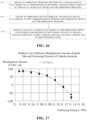
- FIG. 17 is a graph illustrating the correspondence between the misalignment amount of anode tabs and the embossing pressure according to an embodiment of the disclosure.
- the embossing pressure x provided by the rolling device 60 is obtained according to a correspondence between a misalignment amount z 2 of the tabs on the anode electrode 5 and the embossing pressure x.
- the embossing depth y formed by the rolling device 60 is obtained according to the correspondence between the embossing depth y and the embossing pressure x.
- the value of the surplus ⁇ L is obtained according to the embossing depth y and the winding parameters of the winding device 40, to obtain the distance between the first cathode tab 31 and the second cathode tab 32 in the unwinding state of the cathode electrode 3.
- the misalignment amount is obtained by measuring a maximum distance between tabs on a previous anode electrode along a winding trajectory after winding of the previous anode electrode, wherein the previous anode electrode is the same as the anode electrode 5 except that there is no surplus misalignment provided for the previous anode electrode 5.
- the misalignment amount of the tabs on the anode electrode 5 is set to be represented as z 2
- the embossing pressure is set to be represented as x
- the determined value of the embossing pressure x that is required to be provided by the rolling device 60, can be obtained.
- the method for cell winding provided in the embodiments of the disclosure, first, through data fitting analysis of the misalignment amount z 2 of the tabs on the anode electrode 5 and the embossing pressure x , a specific correspondence between the misalignment amount z 2 of the tabs on the anode electrode 5 and the embossing pressure x can be obtained, such that the embossing pressure x corresponding to a relatively small misalignment amount z 2 of the tabs on the anode electrode 5, that needs to be provided by the rolling device 60, can be obtained.
- the embossing depth y required to be formed by the rolling device 60 is obtained.
- the fixed value of the surplus ⁇ L between the first cathode tab 31 and the second cathode tab 32 can be obtained by calculating the embossing depth y and the winding parameters L 1 , L 2 , L 3 , R 1 , and R 2 of the winding device 40, such that the fixed distance between the first cathode tab 31 and the second cathode tab 32 in the unwinding state of the cathode electrode 3 can be obtained.
- the increase in the thickness of the cathode electrode 3 may compensate for the surplus of the misalignment between the first cathode tab 31 and the second cathode tab 32, so that the first cathode tab 31 can be aligned with the second cathode tab 32 after the winding of the cathode electrode 3.
- FIG. 18 is a schematic flow chart of determining the distance between tabs on the cathode electrode, other than the first cathode tab and the second cathode tab, according to yet another embodiment of the disclosure.
- the embossing pressure x provided by the rolling device 60 is obtained according to a correspondence between the misalignment amount z 2 of the tabs on the anode electrode 5 and the embossing pressure x.
- the embossing depth y formed by the rolling device 60 is obtained according to the correspondence between the embossing depth y and the embossing pressure x.
- the distance between the tabs on the cathode electrode 3, other than the first cathode tab 31 and the second cathode tab 32, in the unwinding state of the cathode electrode 3 is obtained according to the embossing depth and the winding parameters of the winding device 40.
- the embossing pressure x that is required to be provided by the rolling device 60, can be obtained according to the correspondence between the misalignment amount z 2 of the tabs on the anode electrode 5 and the embossing pressure x , such that the embossing pressure x, required to be provided by the rolling device 60, corresponding to a relatively small misalignment amount z 2 of the tabs on the anode electrode 5 can be obtained.
- the fixed value of the embossing depth y of the cathode electrode 3 can be obtained according to the correspondence between the embossing depth y and the embossing pressure x , thereby obtaining the value of the winding thickness of the cathode electrode 3.
- the distance between the tabs of the cathode electrode 3, other than the first cathode tab 31 and the second cathode tab 32, in the unwinding state of the cathode electrode 3 can be obtained, so that the cathode electrode 3 can be configured such that after the winding, the tabs of the cathode electrode 3, other than the first cathode tab 31 and the second cathode tab 32, can be are aligned.
- the tabs on the cathode electrode 3 can be aligned after the winding of the cathode electrode 3, thereby improving the winding yield of the cell 10.
- FIG. 19 is a schematic flow chart of a method for cell winding according to another embodiment of the disclosure.
- a method for winding the cell 10 is further provided in the disclosure to avoid the alignment of tabs.
- the method for winding the cell 10 includes the following.
- pre-winding is carried out to obtain and pre-wind an experimental separator, an experimental cathode electrode, and an experimental anode electrode; where after the pre-winding is completed, each two adjacent cathode tabs on the experimental cathode electrode are arranged with a surplus misalignment.
- feeding materials is carried out to obtain a production separator 1, a production cathode electrode 3, and a production anode electrode 5; where the production cathode electrode 3 obtained satisfies that a distance between each two cathode tabs on the production cathode electrode 3 is equal to a distance between the each two cathode tabs on the experimental cathode electrode.
- preparing winding is carried out to fix a starting end of the production separator 1, a starting end of the production cathode electrode 3, and a starting end of the production anode electrode 5 to a winding device.
- embossing is carried out to emboss the production cathode electrode 1 by a rolling device 60 to enable the production cathode electrode 3 subjected to embossing to satisfy that: cathode tabs on the production cathode electrode 3 are aligned with each other after winding; where the embossing is configured to enable the surplus misalignment between each two adjacent cathode tabs on the experimental cathode electrode after the winding to be zero.
- winding is carried out to wind the production separator 1, the production cathode electrode 3, and the production anode electrode 5 by the winding device to form a cell 10.
- the experimental separator, the experimental cathode electrode, and the experimental anode electrode obtained in the pre-winding are different from the production separator, the production cathode electrode, and the production anode electrode obtained in the feeding materials.
- the winding of the experimental cathode electrode in the pre-winding is performed before embossing treatment, aiming to facilitate the measurement and calculation of relevant parameters of the surplus misalignment between different cathode tabs on the experimental cathode electrode.
- the feeding materials involves obtaining the production separator 1, the production cathode electrode 3, and the production anode electrode 5 that are used in actual mass production.
- the pre-winding is carried out to obtain the experimental separator, the experimental cathode electrode, and the experimental anode electrode; where after the pre-winding is completed, each two adjacent cathode tabs on the experimental cathode electrode are arranged with the surplus misalignment.
- the production cathode electrode 3 is configured such that, after the winding of the cell 10, a surplus misalignment between cathode tabs on the production cathode electrode 3 is the same as the surplus misalignment between each two adjacent cathode tabs on the experimental cathode electrode formed during the pre-winding.
- a distance between each two adjacent cathode tabs on the production cathode electrode 3, obtained in the feeding materials, in an unwinding state is preset to be the same as a distance between each two adjacent cathode tabs on the experimental cathode electrode, obtained in the pre-winding, in the unwinding state. Then, during the embossing, the embossing is performed on the production cathode electrode 3 obtained in the feeding materials to thicken the production cathode electrode 3. After the winding of the cell 10, since the production cathode electrode 3 thickens, the cathode tabs on the production cathode electrode 3, which are not thickened originally and thus in surplus misalignment with each other, can be aligned after the actual winding.
- an overall thickness of the production cathode electrode 3 can be made more uniform, so that each pair of tabs on the production cathode electrode 3 can be aligned with each other.
- the misalignment amount of tabs of the cell 10 can be reduced, thereby improving a winding yield of the cell 10.
- the system 100 includes a pre-winding device (not illustrated), a feeding device 20, a rolling device 40, and a winding device 60.
- the pre-winding device configured to obtain the experimental separator, the experimental cathode electrode, and the experimental anode electrode and to complete the pre-winding. After the pre-winding is completed, each two adjacent cathode tabs on the experimental cathode electrode are arranged with a surplus misalignment.
- the feeding device 20 is configured to provide the production separator 1, the production cathode electrode 3, and the production anode electrode 5.
- the production cathode electrode 3 provided by the feeding device 20 satisfies that: a distance between each two adjacent cathode tabs on the production cathode electrode 3 is equal to a distance between the each two adjacent cathode tabs on the experimental cathode electrode.
- the rolling device 60 is configured to emboss the production cathode electrode 3 to enable the production cathode electrode 3 subjected to embossing to satisfy that: cathode tabs on the production cathode electrode3 are aligned with each other after winding.
- the winding device 40 is configured to fix a starting end of the production separator 1, a starting end of the production cathode electrode 3, and a starting end of the production anode electrode 5 and to wind the production separator 1, the production cathode electrode 3, and the production anode electrode 5.
- the system 100 for cell winding provided in this embodiment is configured to operate as follows. Firstly, the pre-winding is carried out to obtain the experimental separator, the experimental cathode electrode, and the experimental anode electrode; where after the pre-winding is completed, each two adjacent cathode tabs on the experimental cathode electrode are arranged with the surplus misalignment. Then, by setting the production cathode electrode 3 provided by the feeding device 20, the production cathode electrode 3 is configured such that, after the pre-winding, a surplus misalignment between each two adjacent cathode tabs on the production cathode electrode 3 is the same as the surplus misalignment between each two adjacent cathode tabs on the experimental cathode electrode.
- a distance between each two adjacent cathode tabs on the production cathode electrode 3 in the unwinding state is preset to be increased. Then, the starting end of the production separator 1, the starting end of the production cathode electrode 3, and the starting end of the production anode electrode 5 are fixed by the winding device 40, and the production separator 1, the production cathode electrode 3, and the production anode electrode 5 are embossed by the rolling device 60 to thicken the production separator 1. Finally, the production separator 1, the production cathode electrode 3, and the production anode electrode 5 are wound by the winding device 40.
- the cathode tabs on the production cathode electrode 3, which are not thickened originally and thus in surplus misalignment with each other, can be aligned after the actual winding. Furthermore, by fixing rolling parameters of the rolling device 60, an overall thickness of the production cathode electrode 3 can be made more uniform, so that each pair of tabs on the production cathode electrode 3 can be aligned with each other. Thus, according to the system 100 for cell winding provided by this embodiment, the misalignment amount of tabs of the cell 10 can be reduced, thereby improving a winding yield of the cell 10.
- the surplus misalignment satisfies that: after the pre-winding, in the each two adjacent cathode tabs on the experimental cathode electrode, one cathode tab is positioned in a first circle, and another cathode tab is positioned in a second circle; there is a surplus between the one cathode tab positioned in the first circle and the another cathode tab positioned in the second circle, where the surplus is a distance from a geometric center of the one cathode tab positioned in the first circle to a geometric center of the another cathode tab positioned in the second circle along a winding trajectory.
- each two adjacent cathode tabs on the experimental cathode electrode are configured such that: after the pre-winding of the experimental cathode electrode, in the each two adjacent cathode tabs on the experimental cathode electrode, one cathode tab is positioned in the first circle of the wound experimental cathode electrode, and another cathode tab is positioned in the second circle of the wound experimental cathode electrode, in other words, the another cathode tab exceeds the one cathode tab, that is, there is a surplus between the another cathode tab and the one cathode tab.
- the thickness of the experimental cathode electrode in the unwinding state may be further increased by the rolling device 60, so that the one cathode tab and the another cathode tab on the experimental cathode electrode, which are originally in surplus misalignment after winding, can be aligned with each other after the winding of the experimental cathode electrode 3, thereby allowing the surplus to be changed from non-zero to zero after the winding of the experimental cathode electrode 3.
- the actual production cathode electrode is designed to be the same as the experimental cathode electrode, and the rolling parameters of the rolling device for the actual production cathode electrode 3 are the same as that for the experimental cathode electrode. This ensures that the cathode tabs on the production cathode electrode, which are originally not thickened and thus have surplus misalignment, align with each other after actual winding.
- FIG. 20 is a schematic flow chart of a method for cell winding according to another embodiment of the disclosure.
- an embossing depth required to be formed by the rolling device 60 is obtained according to the surplus ⁇ L and winding parameters of the winding device 40.
- a correspondence between the embossing depth and an embossing pressure is obtained by presetting and fixing material parameters of the experimental cathode electrode and parameters of the rolling device and applying multiple sets of different embossing pressures to multiple sets of experimental cathode electrodes.
- an embossing pressure required to be provided by the rolling device is obtained according to the correspondence between the embossing depth required and the embossing pressure, to enable the cathode tabs on the production cathode electrode to be aligned with each other after the winding of the production cathode electrode.
- L 1 represents a distance from one end of the first cathode tab 31 adjacent to a first winding bend to the first winding bend
- L 3 represents a distance from a second winding bend to one end of the second cathode tab 32 adjacent to the second winding bend
- L 2 represents a distance from the first winding bend to the second winding bend
- R 1 represents a radius of the first winding bend
- R 2 represents a radius of the second winding bend.
- the embossing depth is set to be represented as y
- the embossing pressure is set to be represented as x
- the embossing depth y required to be formed on the production cathode electrode 3 by the rolling device 60 can be obtained. That is, an increase in the thickness of the production cathode electrode 3, that is required through the embossing, can be obtained.
- a specific correspondence between the embossing depth y and an embossing pressure x can be obtained by presetting and fixing material parameters of the experimental cathode electrode and parameters of the rolling device, applying multiple sets of different embossing pressures to multiple sets of experimental cathode electrodes, and performing data fitting analysis on the embossing depth y and the embossing pressure x, such that a fixed value of the embossing depth y can be determined, and then a fixed value of the embossing pressure x required to be provided corresponding to the embossing depth y can be determined.
- the thickness of the production cathode electrode 3 can be increased under the action of the rolling device 60, and a winding thickness can be uniform, where the winding thickness is the sum of a thickness of the production cathode electrode 3 at a fixed position and the embossing depth y at the fixed position.
- the thickness of the production cathode electrode 3 can be
- the fixed embossing pressure x provided by the rolling device 60 can make the winding thickness of the production cathode electrode 3 more uniform, so that other tabs on the production cathode electrode 3 can also be aligned, which is beneficial to reducing the misalignment amount of the tabs on the production cathode electrode 3, thereby improving the winding yield of the cell 10.
- FIG. 21 is a schematic flow chart of aligning a first cathode tab and a second cathode tab on a cathode electrode with each other according to another embodiment of the disclosure
- FIG. 22 is a schematic flow chart of aligning cathode tabs, other than the first cathode tab and the second cathode tab, on the cathode electrode with each other according to another embodiment of the disclosure.
- an embossing depth required in a region between the first cathode tab 31 and the second cathode tab 32, that are adjacent to one end of the production cathode electrode 3 where winding of the production cathode electrode 3 starts, on the production cathode electrode 3 is obtained according to a surplus ⁇ L between the first cathode tab 31 and the second cathode tab 32 on the experimental cathode electrode that are adjacent to one end of the experimental cathode electrode where winding of the experimental cathode electrode starts.
- an embossing pressure required to be applied by the rolling device 60 to the region between the first cathode tab 31 and the second cathode tab 32 on the experimental cathode electrode is obtained according to the function relationship between the embossing depth and the embossing pressure.
- an embossing depth required in a region between the each two adjacent cathode tabs, other than the first cathode tab and the second cathode tab, on the experimental cathode electrode is obtained according to a surplus between the each two adjacent cathode tabs, other than the first cathode tab and the second cathode tab, on the experimental cathode electrode.
- an embossing pressure required to be applied by the rolling device to the region between the each two adjacent cathode tabs, other than the first cathode tab and the second cathode tab, on the experimental cathode electrode is obtained according to the function relationship between the embossing depth and the embossing pressure.
- the embossing depth required in the region between the first cathode tab 31 and the second cathode tab 32 on the production cathode electrode 3 needs to be designed to be the same as the embossing depth required in the region between each two adjacent tabs that are different from the first cathode tab 31 and the second cathode tab 32 at the starting end of the production cathode electrode 3.
- the surplus between each two adjacent cathode tabs of the cathode electrode 3 can be designed to be different.
- FIG. 23 is a schematic flow chart of obtaining a correspondence between a misalignment amount of cathode tabs and an embossing pressure according to another embodiment of the disclosure.
- multiple sets of different embossing depths required to be formed by the rolling device 60 on multiple sets of experimental cathode electrodes are obtained according to the winding parameters of the winding device 40 and multiple sets of different surpluses of the multiple sets of experimental cathode electrodes.
- multiple sets of different embossing pressures required to be applied by the rolling device to the multiple sets of experimental cathode electrodes are obtained according to the multiple sets of different embossing depths required by the multiple sets of experimental cathode electrodes.
- multiple sets of misalignment amounts of tabs on the multiple sets of experimental cathode electrodes after winding are obtained by respectively applying the multiple sets of different embossing pressures required to the multiple sets of experimental cathode electrodes.
- multiple sets of surpluses ⁇ L of the first cathode electrode tabs 31 and the second cathode electrode tabs 32 of the production cathode electrode 3 can be designed.
- the misalignment amount of tabs on the experimental cathode electrode or of tabs on the production cathode electrode 3 and the embossing pressure is set to be represented as z 1
- the misalignment amount of the tabs on the experimental cathode electrode is set to be represented as z 1
- the embossing pressure is set to be represented as x
- z 1 f x 2 + g x + h and the minimum value (i.e., zero) of the misalignment amount z 1 of the tabs on the experimental cathode electrode 3, a determined value of the embossing pressure x, that is required to be provided by the rolling device 60 to the production cathode electrode 3, can be obtained, such that misalignment amount z 1 of tabs of the wound cell 10 is equal to zero.
- a determined value of the embossing depth y can be obtained according to the determined value of the embossing pressure x, so that different determined values of surpluses between different cathode tabs on the production cathode electrode 3 can be obtained according to the winding parameters L 1 , L 2 , L 3 , R 1 , and R 2 .
- FIG. 24 is schematic flow chart of obtaining a correspondence between a misalignment amount of anode tabs and an embossing pressure according to another embodiment of the disclosure.
- multiple sets of different embossing pressures required to be applied by the rolling device 60 to the multiple sets of experimental anode electrodes are obtained according to the multiple sets of different embossing depths required by the multiple sets of experimental anode electrodes.
- multiple sets of misalignment amounts of tabs on the multiple sets of experimental anode electrodes after winding are obtained by applying the multiple sets of different embossing pressures required respectively to the multiple sets of experimental anode electrodes.
- the misalignment amount of the tabs on the experimental anode electrode is set to be represented as z 2
- the misalignment amount of the tabs on the experimental anode electrode is set to be represented as z 2
- the embossing pressure is set to be represented as x
- a determined value of the embossing pressure x that is required to be provided by the rolling device 60, can be obtained, such that misalignment amount z 2 of anode tabs of the wound cell 10 is equal to zero.
- a determined value of the embossing depth y can be obtained according to the determined value of the embossing pressure x, so that different determined values of surpluses between different anode tabs on the production anode electrode 5 can be obtained according to the winding parameters L 1 , L 2 , L 3 , R 1 , and R 2 .
Landscapes
- Engineering & Computer Science (AREA)
- Manufacturing & Machinery (AREA)
- Chemical & Material Sciences (AREA)
- Chemical Kinetics & Catalysis (AREA)
- Electrochemistry (AREA)
- General Chemical & Material Sciences (AREA)
- Secondary Cells (AREA)
- Primary Cells (AREA)
Applications Claiming Priority (1)
| Application Number | Priority Date | Filing Date | Title |
|---|---|---|---|
| CN202310787846.3A CN116598569A (zh) | 2023-06-29 | 2023-06-29 | 电芯卷绕的方法及电芯卷绕系统 |
Publications (2)
| Publication Number | Publication Date |
|---|---|
| EP4485597A2 true EP4485597A2 (de) | 2025-01-01 |
| EP4485597A3 EP4485597A3 (de) | 2025-07-30 |
Family
ID=87611941
Family Applications (1)
| Application Number | Title | Priority Date | Filing Date |
|---|---|---|---|
| EP24185411.6A Pending EP4485597A3 (de) | 2023-06-29 | 2024-06-28 | Verfahren zur zellwicklung und system zur zellwicklung |
Country Status (4)
| Country | Link |
|---|---|
| US (1) | US20250006975A1 (de) |
| EP (1) | EP4485597A3 (de) |
| CN (1) | CN116598569A (de) |
| WO (1) | WO2025001123A1 (de) |
Families Citing this family (2)
| Publication number | Priority date | Publication date | Assignee | Title |
|---|---|---|---|---|
| CN116598569A (zh) * | 2023-06-29 | 2023-08-15 | 厦门海辰储能科技股份有限公司 | 电芯卷绕的方法及电芯卷绕系统 |
| CN118448748B (zh) * | 2024-05-27 | 2025-01-21 | 益阳长天新能源科技有限公司 | 一种极耳错位修正方法 |
Family Cites Families (8)
| Publication number | Priority date | Publication date | Assignee | Title |
|---|---|---|---|---|
| CN207864411U (zh) * | 2017-12-07 | 2018-09-14 | 合肥国轩高科动力能源有限公司 | 一种极片卷绕机及其三角辊 |
| CN109585902B (zh) * | 2018-12-24 | 2024-11-12 | 江苏正力新能电池技术股份有限公司 | 可调节极耳错位的电芯卷绕系统和方法 |
| CN113097570B (zh) * | 2021-03-26 | 2022-08-30 | 宁德新能源科技有限公司 | 卷绕电芯及用于其的极耳错位测量方法 |
| CN214378574U (zh) * | 2021-03-31 | 2021-10-08 | 深圳吉阳智能科技有限公司 | 极片卷绕纠正装置和卷绕机 |
| CN116263321A (zh) * | 2022-10-21 | 2023-06-16 | 江苏耀宁新能源创新科技有限公司 | 一种在线纠正极耳错位方法 |
| CN218996812U (zh) * | 2022-11-02 | 2023-05-09 | 广州融捷能源科技有限公司 | 一种具有极耳调整功能的卷绕电芯制备系统 |
| CN115882166B (zh) * | 2022-11-30 | 2025-12-16 | 广东利元亨智能装备股份有限公司 | 电芯极耳错位优化方法和控制器 |
| CN116598569A (zh) * | 2023-06-29 | 2023-08-15 | 厦门海辰储能科技股份有限公司 | 电芯卷绕的方法及电芯卷绕系统 |
-
2023
- 2023-06-29 CN CN202310787846.3A patent/CN116598569A/zh active Pending
-
2024
- 2024-01-25 WO PCT/CN2024/074048 patent/WO2025001123A1/zh not_active Ceased
- 2024-06-28 EP EP24185411.6A patent/EP4485597A3/de active Pending
- 2024-06-28 US US18/759,386 patent/US20250006975A1/en active Pending
Also Published As
| Publication number | Publication date |
|---|---|
| CN116598569A (zh) | 2023-08-15 |
| WO2025001123A1 (zh) | 2025-01-02 |
| US20250006975A1 (en) | 2025-01-02 |
| EP4485597A3 (de) | 2025-07-30 |
Similar Documents
| Publication | Publication Date | Title |
|---|---|---|
| EP4485597A2 (de) | Verfahren zur zellwicklung und system zur zellwicklung | |
| CN114454534B (zh) | 用于加工电极带的砑光机和方法 | |
| CN103503217A (zh) | 用于制造电极线圈的方法和设备 | |
| US8820132B2 (en) | Method and facility for producing separator for use in polymer electrolyte fuel cell | |
| US10525515B2 (en) | Roll-bending processing method and processing device | |
| CN1599197A (zh) | 铁心、其制造方法及制造装置 | |
| CN117976955B (zh) | 电芯极耳间距纠正方法、装置及标准极耳间距获取方法 | |
| EP3486975B1 (de) | Verfahren zur herstellung einer sekundärbatterieelektrode | |
| WO2023015879A1 (zh) | 弹性支撑件、电解槽、制造设备和制造方法 | |
| US4481003A (en) | Method of producing itegral electrode structure for electron gun | |
| CN112743242A (zh) | 调高器的高精度控制方法、装置和调高器控制设备 | |
| CN118380626B (zh) | 卷针半径的调整方法、装置、设备及存储介质 | |
| CN115415329B (zh) | 一种控制板形缺陷延伸率的设定方法 | |
| CN107453567A (zh) | 一种盘式电机定子铁心的加工方法 | |
| CN119998972B (zh) | 电极材料卷绕装置 | |
| KR102758781B1 (ko) | 전극의 사행 보정장치 및 전극의 사행 보정방법 | |
| CN115451851A (zh) | 一种快速确定极耳间距尺寸的方法、装置及电池生产系统 | |
| JPH08300045A (ja) | 板の曲げ加工方法 | |
| EP4601022A1 (de) | Verfahren zum walzen einer elektrode | |
| US20250128310A1 (en) | Battery manufacturing device and manufacturing method | |
| CN221805791U (zh) | 电池的电极片及电池 | |
| CN117019984B (zh) | 一种冲压圆料片落料排板方法、系统 | |
| JP2981996B2 (ja) | 磁気ヘッドの加工方法 | |
| KR20230146291A (ko) | 코팅부와 탭부의 연신 차이 측정장치 | |
| US20260011708A1 (en) | Secondary battery electrode plate manufacturing apparatus including die parallelism monitoring device and secondary battery electrode plate manufacturing method |
Legal Events
| Date | Code | Title | Description |
|---|---|---|---|
| PUAI | Public reference made under article 153(3) epc to a published international application that has entered the european phase |
Free format text: ORIGINAL CODE: 0009012 |
|
| STAA | Information on the status of an ep patent application or granted ep patent |
Free format text: STATUS: THE APPLICATION HAS BEEN PUBLISHED |
|
| AK | Designated contracting states |
Kind code of ref document: A2 Designated state(s): AL AT BE BG CH CY CZ DE DK EE ES FI FR GB GR HR HU IE IS IT LI LT LU LV MC ME MK MT NL NO PL PT RO RS SE SI SK SM TR |
|
| RAP1 | Party data changed (applicant data changed or rights of an application transferred) |
Owner name: HITHIUM TECH HK LIMITED |
|
| PUAL | Search report despatched |
Free format text: ORIGINAL CODE: 0009013 |
|
| AK | Designated contracting states |
Kind code of ref document: A3 Designated state(s): AL AT BE BG CH CY CZ DE DK EE ES FI FR GB GR HR HU IE IS IT LI LT LU LV MC ME MK MT NL NO PL PT RO RS SE SI SK SM TR |
|
| RIC1 | Information provided on ipc code assigned before grant |
Ipc: H01M 10/04 20060101AFI20250624BHEP Ipc: H01M 10/0587 20100101ALI20250624BHEP |
|
| STAA | Information on the status of an ep patent application or granted ep patent |
Free format text: STATUS: REQUEST FOR EXAMINATION WAS MADE |
|
| 17P | Request for examination filed |
Effective date: 20251230 |
|
| STAA | Information on the status of an ep patent application or granted ep patent |
Free format text: STATUS: EXAMINATION IS IN PROGRESS |
|
| 17Q | First examination report despatched |
Effective date: 20260213 |