EP4485436A1 - Logo lighting device for a vehicle, in particular motor vehicle - Google Patents
Logo lighting device for a vehicle, in particular motor vehicle Download PDFInfo
- Publication number
- EP4485436A1 EP4485436A1 EP24183367.2A EP24183367A EP4485436A1 EP 4485436 A1 EP4485436 A1 EP 4485436A1 EP 24183367 A EP24183367 A EP 24183367A EP 4485436 A1 EP4485436 A1 EP 4485436A1
- Authority
- EP
- European Patent Office
- Prior art keywords
- light
- light guide
- vehicle
- guide
- illuminating device
- Prior art date
- Legal status (The legal status is an assumption and is not a legal conclusion. Google has not performed a legal analysis and makes no representation as to the accuracy of the status listed.)
- Pending
Links
Images
Classifications
-
- B—PERFORMING OPERATIONS; TRANSPORTING
- B60—VEHICLES IN GENERAL
- B60Q—ARRANGEMENT OF SIGNALLING OR LIGHTING DEVICES, THE MOUNTING OR SUPPORTING THEREOF OR CIRCUITS THEREFOR, FOR VEHICLES IN GENERAL
- B60Q1/00—Arrangement of optical signalling or lighting devices, the mounting or supporting thereof or circuits therefor
- B60Q1/26—Arrangement of optical signalling or lighting devices, the mounting or supporting thereof or circuits therefor the devices being primarily intended to indicate the vehicle, or parts thereof, or to give signals, to other traffic
- B60Q1/2661—Arrangement of optical signalling or lighting devices, the mounting or supporting thereof or circuits therefor the devices being primarily intended to indicate the vehicle, or parts thereof, or to give signals, to other traffic mounted on parts having other functions
-
- B—PERFORMING OPERATIONS; TRANSPORTING
- B60—VEHICLES IN GENERAL
- B60R—VEHICLES, VEHICLE FITTINGS, OR VEHICLE PARTS, NOT OTHERWISE PROVIDED FOR
- B60R13/00—Elements for body-finishing, identifying, or decorating; Arrangements or adaptations for advertising purposes
- B60R13/005—Manufacturers' emblems, name plates, bonnet ornaments, mascots or the like; Mounting means therefor
-
- G—PHYSICS
- G09—EDUCATION; CRYPTOGRAPHY; DISPLAY; ADVERTISING; SEALS
- G09F—DISPLAYING; ADVERTISING; SIGNS; LABELS OR NAME-PLATES; SEALS
- G09F13/00—Illuminated signs; Luminous advertising
- G09F13/04—Signs, boards or panels, illuminated from behind the insignia
- G09F13/0404—Signs, boards or panels, illuminated from behind the insignia the light source being enclosed in a box forming the character of the sign
-
- G—PHYSICS
- G09—EDUCATION; CRYPTOGRAPHY; DISPLAY; ADVERTISING; SEALS
- G09F—DISPLAYING; ADVERTISING; SIGNS; LABELS OR NAME-PLATES; SEALS
- G09F13/00—Illuminated signs; Luminous advertising
- G09F13/04—Signs, boards or panels, illuminated from behind the insignia
- G09F13/0418—Constructional details
-
- G—PHYSICS
- G09—EDUCATION; CRYPTOGRAPHY; DISPLAY; ADVERTISING; SEALS
- G09F—DISPLAYING; ADVERTISING; SIGNS; LABELS OR NAME-PLATES; SEALS
- G09F13/00—Illuminated signs; Luminous advertising
- G09F13/04—Signs, boards or panels, illuminated from behind the insignia
- G09F13/0418—Constructional details
- G09F13/044—Signs, boards or panels mounted on vehicles
-
- G—PHYSICS
- G09—EDUCATION; CRYPTOGRAPHY; DISPLAY; ADVERTISING; SEALS
- G09F—DISPLAYING; ADVERTISING; SIGNS; LABELS OR NAME-PLATES; SEALS
- G09F13/00—Illuminated signs; Luminous advertising
- G09F13/04—Signs, boards or panels, illuminated from behind the insignia
- G09F13/0418—Constructional details
- G09F13/049—Edge illuminated signs, boards or panels
-
- G—PHYSICS
- G09—EDUCATION; CRYPTOGRAPHY; DISPLAY; ADVERTISING; SEALS
- G09F—DISPLAYING; ADVERTISING; SIGNS; LABELS OR NAME-PLATES; SEALS
- G09F13/00—Illuminated signs; Luminous advertising
- G09F13/18—Edge-illuminated signs
-
- G—PHYSICS
- G09—EDUCATION; CRYPTOGRAPHY; DISPLAY; ADVERTISING; SEALS
- G09F—DISPLAYING; ADVERTISING; SIGNS; LABELS OR NAME-PLATES; SEALS
- G09F21/00—Mobile visual advertising
- G09F21/04—Mobile visual advertising by land vehicles
Definitions
- This invention relates to a logo lighting device for a vehicle, in particular a motor vehicle.
- the patent DE102008044854A1 describes a logo lighting device for a vehicle wherein a casing is made of transparent polycarbonate. A layer of partly transparent metal (for example silver, aluminium, or the like) of some tens of nanometres is applied to the outside at the point where the light must emerge at the logo. The remaining area of the casing is covered in chrome plating so that light does not escape. A lighting device (for example, consisting of SMD LEDs on a printed circuit) is installed in the inner cavity of the casing and protected from the environment via sealing.
- the device illustrated in the patent mentioned above is formed from many different parts that must be assembled together; thus, its production is complex and costly.
- the aim of this invention is to provide a logo display device for a vehicle that is extremely simple to build and to assemble and costs very little.
- number 1 identifies a logo lighting device for a vehicle, in particular a motor vehicle, comprising a light-proof front screen portion 2 provided with an integral window 3 that light can pass through and that has edges that reproduce a logo, schematically depicted in the figure with the letter R arranged in a circle.
- the logo may consist of several different windows that are separated from each other by light-proof parts.
- the screen 2 may be printed in a single piece of transparent plastic covered in light-proof paint that is not deposited on the windows 3 that produce the logo.
- the windows may not be completely transparent and be made of plastic provided with embossing, plastic covered in metallization able to allow light rays to pass through, or opaline material.
- the device 1 also comprises a central illuminating device 4 designed to light the integral window 3 with a spatially uniform light intensity.
- the central illuminating device 4 comprises a first light guide 5 that, in the embodiment, extends along a first straight direction (D1, see Figure 3 ) and is provided with a light source 6 at one end thereof (typically an LED) that supplies light at the input of the guide (schematically depicted with arrows in Figure 1 ).
- the light guide 5 is designed to output rays that radially extend along a second direction (D2) transverse to the first D1.
- the light guide 5 could also be different from that illustrated in the drawings, for example curved with more bends or comprising straight portions and curved ones.
- the central illuminating device 4 comprises a second light guide 7 having a reduced dimension (the thickness along Z) compared to the dimensions X, Y that define its extension (typically a guide shaped like a flat wall).
- the guide has, in the example, a straight side 8 (see Figure 3 ) acting as a collimator which is arranged facing the first straight guide 5 and designed to receive output rays at the first guide 5 that extend along D2.
- the second light guide 7 shaped like a flat wall is configured to output light radiation R that extends parallel to a main direction D3 (for example, transverse to the lying plane of the flat wall) and is directed towards the screen 2 and, thus, the integral window 3 in order to light it completely.
- the flat wall 7 lights up with a spatially uniform light intensity along its whole extension along X and Y.
- the device 1 is installed in the vehicle so that the light radiation output at the window 3 along D3 is also parallel to the axis of the vehicle in which the logo lighting device is installed (see Figure 2 ). In this way, the window 3 of the device 1 is seen completely lit up by an observer that is located in front of the vehicle.
- a rear cover 9 configured to house the central illuminating device 4 can be connected to the front portion of the screen 2 using known fasteners, for example screws (not illustrated).
- the cover 9 is not an essential element of the device and may also not be included.
- the first light guide 5 and the second light guide 7 shaped like a flat wall are made via moulding of a single piece of plastic. In this way, production costs are reduced and assembly is simplified.
- the rear cover 9 - if included - is delimited by a flat reflecting wall 10 facing the central illuminating device 4.
- This wall 10 can be covered by a reflecting surface, for example a metal surface, or, more simply, the cover 9 may be made of light-coloured, for example white, plastic.
- the flat wall that creates the central illuminating device 4 is delimited by two opposite faces 7-a, 7-b at least one of which (7-b in the example) is provided with light outcoupling elements that allow the generation of light radiation developing parallel to one another.
- the light out-coupling elements comprise prisms, embossing, paint, or metallization.
Landscapes
- Engineering & Computer Science (AREA)
- Physics & Mathematics (AREA)
- General Physics & Mathematics (AREA)
- Theoretical Computer Science (AREA)
- Mechanical Engineering (AREA)
- Business, Economics & Management (AREA)
- Accounting & Taxation (AREA)
- Marketing (AREA)
- Non-Portable Lighting Devices Or Systems Thereof (AREA)
Abstract
A logo lighting device (1) for a vehicle, in particular a motor vehicle, including: a light-proof front screen portion (2) provided with at least one integral window (3) that light can pass through and that has boundaries reproducing a logo; a central illuminating device (4) adapted to illuminate the integral window (3); the central illuminating device (4) including a first light guide (5) that extends along a first direction (D1) and is provided with a light source (6) at one end thereof, the first light guide (5) being adapted to output rays that extend along a second direction (D2) which is transversal to the first direction (D1); the central illuminating device (4) including a second light guide (7) having a reduced thickness with respect to its extension and having a side (8) which is arranged facing the first light guide (5) and which is configured to receive at least a part of the output rays at the first guide (4) along the second direction (D2); the second light guide (7) is configured to output light radiation that extends parallel to a third main direction and that is directed towards the integral window (3) .
Description
- This patent application claims priority from
Italian patent application no. 102023000013425 filed on 28 June 2023 - This invention relates to a logo lighting device for a vehicle, in particular a motor vehicle.
- The patent
DE102008044854A1 describes a logo lighting device for a vehicle wherein a casing is made of transparent polycarbonate. A layer of partly transparent metal (for example silver, aluminium, or the like) of some tens of nanometres is applied to the outside at the point where the light must emerge at the logo. The remaining area of the casing is covered in chrome plating so that light does not escape. A lighting device (for example, consisting of SMD LEDs on a printed circuit) is installed in the inner cavity of the casing and protected from the environment via sealing. The device illustrated in the patent mentioned above is formed from many different parts that must be assembled together; thus, its production is complex and costly. - The aim of this invention is to provide a logo display device for a vehicle that is extremely simple to build and to assemble and costs very little.
- The above-mentioned aim is achieved with this invention in that it relates to a logo display device for a vehicle of the type described in claim 1.
- The invention will be illustrated with reference to the accompanying figures wherein:
-
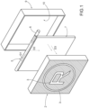
Figure 1 illustrates, in a perspective, exploded view, a logo display device for a vehicle produced according to the precepts of this invention; -
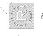
Figure 2 illustrates, in a front view, the device inFigure 1 installed on a front portion of a vehicle; -
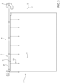
Figure 3 illustrates, in a front view, a component part of the device inFigure 1 ; and -
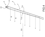
Figure 4 illustrates the operating principle of the part illustrated inFigure 3 . - With reference to
Figure 1 , number 1 identifies a logo lighting device for a vehicle, in particular a motor vehicle, comprising a light-prooffront screen portion 2 provided with anintegral window 3 that light can pass through and that has edges that reproduce a logo, schematically depicted in the figure with the letter R arranged in a circle. The logo may consist of several different windows that are separated from each other by light-proof parts. - The
screen 2 may be printed in a single piece of transparent plastic covered in light-proof paint that is not deposited on thewindows 3 that produce the logo. The windows may not be completely transparent and be made of plastic provided with embossing, plastic covered in metallization able to allow light rays to pass through, or opaline material. - The device 1 also comprises a central
illuminating device 4 designed to light theintegral window 3 with a spatially uniform light intensity. The centralilluminating device 4 comprises afirst light guide 5 that, in the embodiment, extends along a first straight direction (D1, seeFigure 3 ) and is provided with alight source 6 at one end thereof (typically an LED) that supplies light at the input of the guide (schematically depicted with arrows inFigure 1 ). Thelight guide 5 is designed to output rays that radially extend along a second direction (D2) transverse to the first D1. Thelight guide 5 could also be different from that illustrated in the drawings, for example curved with more bends or comprising straight portions and curved ones. - The central
illuminating device 4 comprises asecond light guide 7 having a reduced dimension (the thickness along Z) compared to the dimensions X, Y that define its extension (typically a guide shaped like a flat wall). The guide has, in the example, a straight side 8 (seeFigure 3 ) acting as a collimator which is arranged facing the firststraight guide 5 and designed to receive output rays at thefirst guide 5 that extend along D2. - The
second light guide 7 shaped like a flat wall is configured to output light radiation R that extends parallel to a main direction D3 (for example, transverse to the lying plane of the flat wall) and is directed towards thescreen 2 and, thus, theintegral window 3 in order to light it completely. Basically, theflat wall 7 lights up with a spatially uniform light intensity along its whole extension along X and Y. - In use, the device 1 is installed in the vehicle so that the light radiation output at the
window 3 along D3 is also parallel to the axis of the vehicle in which the logo lighting device is installed (seeFigure 2 ). In this way, thewindow 3 of the device 1 is seen completely lit up by an observer that is located in front of the vehicle. - A
rear cover 9 configured to house the centralilluminating device 4 can be connected to the front portion of thescreen 2 using known fasteners, for example screws (not illustrated). - The
cover 9 is not an essential element of the device and may also not be included. - Conveniently, the
first light guide 5 and thesecond light guide 7 shaped like a flat wall are made via moulding of a single piece of plastic. In this way, production costs are reduced and assembly is simplified. - Conveniently, the rear cover 9 - if included - is delimited by a flat reflecting
wall 10 facing the centralilluminating device 4. Thiswall 10 can be covered by a reflecting surface, for example a metal surface, or, more simply, thecover 9 may be made of light-coloured, for example white, plastic. - As can be seen in
Figure 4 , the flat wall that creates the centralilluminating device 4 is delimited by two opposite faces 7-a, 7-b at least one of which (7-b in the example) is provided with light outcoupling elements that allow the generation of light radiation developing parallel to one another. - Conveniently, the light out-coupling elements comprise prisms, embossing, paint, or metallization.
Claims (8)
- A logo lighting device (1) for a vehicle, in particular a motor vehicle, characterized by comprising:- a light-proof front screen portion (2) provided with at least one integral window (3) that light can pass through and that has boundaries reproducing a logo;- a central illuminating device (4) adapted to illuminate the integral window (3); the central illuminating device (4) comprises a first light guide (5) which extends, at least for a stretch thereof, along a first direction (D1) and is provided with a light source (6) at one end thereof, said first light guide (5) being adapted to output rays which extend along a second direction (D2) which is transversal to the first direction (D1); the central illuminating device (4) comprising a second light guide having a dimension (Z) which is reduced with respect to the dimensions X, Y defining its extension and having at least one side (8) arranged facing the first light guide (5) and configured to receive at least a part of the output rays at the first guide (4) along the second direction (D2); said second light guide (7) being configured to output light radiations which extend parallel to a third main direction (D3) and are directed towards the integral window (3).
- - The device according to claim 1, wherein the first light guide (5) and the second light guide (7) are made in a single piece of plastic material.
- - The device according to claim 1 or 2, wherein a rear cover (9) is provided, which is delimited by a flat reflecting wall (10) facing the central illuminating device.
- - The device according to any one of the preceding claims, wherein the second light guide (7) is delimited by two opposite faces (7-a, 7-b) at least one of which (7-b) is provided with light outcoupling elements that allow the generation of light radiations developing parallel to one another.
- - The device according to claim 4, wherein the light out-coupling elements comprise prisms, embossing, paint, metallization.
- - The device according to any one of the preceding claims, wherein said first light guide (5) is of the rectilinear type.
- - The device according to any one of the preceding claims, wherein said second light guide (5) is shaped like a flat wall.
- - The device according to claim 7, wherein the light guide (7) is shaped like a flat wall and is configured to output light radiation R which extends transversely to the lying plane of the flat wall.
Applications Claiming Priority (1)
| Application Number | Priority Date | Filing Date | Title |
|---|---|---|---|
| IT102023000013425A IT202300013425A1 (en) | 2023-06-28 | 2023-06-28 | DEVICE FOR ILLUMINATING A VEHICLE LOGO, ESPECIALLY A MOTOR VEHICLE |
Publications (1)
| Publication Number | Publication Date |
|---|---|
| EP4485436A1 true EP4485436A1 (en) | 2025-01-01 |
Family
ID=88097739
Family Applications (1)
| Application Number | Title | Priority Date | Filing Date |
|---|---|---|---|
| EP24183367.2A Pending EP4485436A1 (en) | 2023-06-28 | 2024-06-20 | Logo lighting device for a vehicle, in particular motor vehicle |
Country Status (3)
| Country | Link |
|---|---|
| EP (1) | EP4485436A1 (en) |
| CN (1) | CN119218097A (en) |
| IT (1) | IT202300013425A1 (en) |
Citations (5)
| Publication number | Priority date | Publication date | Assignee | Title |
|---|---|---|---|---|
| DE10032927A1 (en) * | 2000-07-06 | 2002-01-17 | Hella Kg Hueck & Co | Lighting device e.g. for illuminating motor vehicle interior, uses plate-shaped or bar-type light-guide |
| DE102008044854A1 (en) | 2008-08-28 | 2010-03-04 | Adelmann, Lothar, Dipl.-Designer | Method for illumination of chromium colored and planar mark emblem of motor vehicle of old type, involves laying light source on printed circuit board, and integrating protection devices in emblem to protect emblem against over voltage |
| US20130003397A1 (en) * | 2009-12-11 | 2013-01-03 | Alain Buisson | Signal light device for a motor vehicle |
| WO2016191487A1 (en) * | 2015-05-26 | 2016-12-01 | Optoglo Inc. | Illuminated window display |
| US10030846B2 (en) * | 2012-02-14 | 2018-07-24 | Svv Technology Innovations, Inc. | Face-lit waveguide illumination systems |
-
2023
- 2023-06-28 IT IT102023000013425A patent/IT202300013425A1/en unknown
-
2024
- 2024-06-20 EP EP24183367.2A patent/EP4485436A1/en active Pending
- 2024-06-25 CN CN202410823196.8A patent/CN119218097A/en active Pending
Patent Citations (5)
| Publication number | Priority date | Publication date | Assignee | Title |
|---|---|---|---|---|
| DE10032927A1 (en) * | 2000-07-06 | 2002-01-17 | Hella Kg Hueck & Co | Lighting device e.g. for illuminating motor vehicle interior, uses plate-shaped or bar-type light-guide |
| DE102008044854A1 (en) | 2008-08-28 | 2010-03-04 | Adelmann, Lothar, Dipl.-Designer | Method for illumination of chromium colored and planar mark emblem of motor vehicle of old type, involves laying light source on printed circuit board, and integrating protection devices in emblem to protect emblem against over voltage |
| US20130003397A1 (en) * | 2009-12-11 | 2013-01-03 | Alain Buisson | Signal light device for a motor vehicle |
| US10030846B2 (en) * | 2012-02-14 | 2018-07-24 | Svv Technology Innovations, Inc. | Face-lit waveguide illumination systems |
| WO2016191487A1 (en) * | 2015-05-26 | 2016-12-01 | Optoglo Inc. | Illuminated window display |
Also Published As
| Publication number | Publication date |
|---|---|
| CN119218097A (en) | 2024-12-31 |
| IT202300013425A1 (en) | 2024-12-28 |
Similar Documents
| Publication | Publication Date | Title |
|---|---|---|
| US20190170317A1 (en) | Light device, especially signal lamp, for motor vehicles | |
| CN109383410B (en) | Radar-capable illuminated signs for vehicles | |
| EP3663641B1 (en) | Vehicle lighting and/or signalling device | |
| US10053004B2 (en) | Headlamp with backlit side bezel signature image | |
| US10214140B2 (en) | Elongate illuminated automotive design element | |
| EP3106348B1 (en) | Vehicle light and related manufacturing method | |
| US11293621B2 (en) | Light guide for lamps and related lamp for motor vehicles | |
| US20160231493A1 (en) | Light assembly for illuminating an emblem | |
| CN105805698A (en) | Light transmission device | |
| DE19621148A1 (en) | Lighting element, especially e.g. for use in motor vehicles | |
| WO2009110476A1 (en) | Illuminating device | |
| JP6497054B2 (en) | Vehicle light guide member, vehicle lamp | |
| CN105774684A (en) | Application structure for motor vehicles | |
| CN112638678A (en) | Vehicle door seal supporting a light source | |
| EP3043152A1 (en) | Glow ring for instrument panel | |
| EP3608582B1 (en) | Multi-sided luminous lighting member and three-dimensional lighting device using same | |
| EP1559614B1 (en) | Outside mirror apparatus for vehicle and illuminating unit for the outside mirror apparatus | |
| EP4485436A1 (en) | Logo lighting device for a vehicle, in particular motor vehicle | |
| EP2803902A1 (en) | Lighting apparatus and vehicle light | |
| CN108361648B (en) | Lighting device comprising a shade with a 3D pattern | |
| JP6320110B2 (en) | Vehicle lamp with license lamp | |
| WO2007092825A1 (en) | Direct lighting vehicular lamp | |
| JP7616149B2 (en) | Luminous Emblem | |
| US11852313B2 (en) | Light device of a vehicle to ensure a dark, or colored appearance of at least a part of the light device in the off state | |
| CN108351082B (en) | Method for manufacturing design equipment for vehicles and lighting devices |
Legal Events
| Date | Code | Title | Description |
|---|---|---|---|
| PUAI | Public reference made under article 153(3) epc to a published international application that has entered the european phase |
Free format text: ORIGINAL CODE: 0009012 |
|
| STAA | Information on the status of an ep patent application or granted ep patent |
Free format text: STATUS: THE APPLICATION HAS BEEN PUBLISHED |
|
| AK | Designated contracting states |
Kind code of ref document: A1 Designated state(s): AL AT BE BG CH CY CZ DE DK EE ES FI FR GB GR HR HU IE IS IT LI LT LU LV MC ME MK MT NL NO PL PT RO RS SE SI SK SM TR |
|
| STAA | Information on the status of an ep patent application or granted ep patent |
Free format text: STATUS: REQUEST FOR EXAMINATION WAS MADE |
|
| 17P | Request for examination filed |
Effective date: 20250627 |