EP3106348B1 - Vehicle light and related manufacturing method - Google Patents
Vehicle light and related manufacturing method Download PDFInfo
- Publication number
- EP3106348B1 EP3106348B1 EP16172050.3A EP16172050A EP3106348B1 EP 3106348 B1 EP3106348 B1 EP 3106348B1 EP 16172050 A EP16172050 A EP 16172050A EP 3106348 B1 EP3106348 B1 EP 3106348B1
- Authority
- EP
- European Patent Office
- Prior art keywords
- main light
- substrate
- light
- light source
- vehicle
- Prior art date
- Legal status (The legal status is an assumption and is not a legal conclusion. Google has not performed a legal analysis and makes no representation as to the accuracy of the status listed.)
- Active
Links
Images


Classifications
-
- F—MECHANICAL ENGINEERING; LIGHTING; HEATING; WEAPONS; BLASTING
- F21—LIGHTING
- F21S—NON-PORTABLE LIGHTING DEVICES; SYSTEMS THEREOF; VEHICLE LIGHTING DEVICES SPECIALLY ADAPTED FOR VEHICLE EXTERIORS
- F21S41/00—Illuminating devices specially adapted for vehicle exteriors, e.g. headlamps
- F21S41/20—Illuminating devices specially adapted for vehicle exteriors, e.g. headlamps characterised by refractors, transparent cover plates, light guides or filters
- F21S41/29—Attachment thereof
-
- B—PERFORMING OPERATIONS; TRANSPORTING
- B26—HAND CUTTING TOOLS; CUTTING; SEVERING
- B26D—CUTTING; DETAILS COMMON TO MACHINES FOR PERFORATING, PUNCHING, CUTTING-OUT, STAMPING-OUT OR SEVERING
- B26D7/00—Details of apparatus for cutting, cutting-out, stamping-out, punching, perforating, or severing by means other than cutting
- B26D7/01—Means for holding or positioning work
- B26D7/015—Means for holding or positioning work for sheet material or piles of sheets
-
- B—PERFORMING OPERATIONS; TRANSPORTING
- B26—HAND CUTTING TOOLS; CUTTING; SEVERING
- B26D—CUTTING; DETAILS COMMON TO MACHINES FOR PERFORATING, PUNCHING, CUTTING-OUT, STAMPING-OUT OR SEVERING
- B26D7/00—Details of apparatus for cutting, cutting-out, stamping-out, punching, perforating, or severing by means other than cutting
- B26D7/08—Means for treating work or cutting member to facilitate cutting
- B26D7/10—Means for treating work or cutting member to facilitate cutting by heating
-
- B—PERFORMING OPERATIONS; TRANSPORTING
- B26—HAND CUTTING TOOLS; CUTTING; SEVERING
- B26D—CUTTING; DETAILS COMMON TO MACHINES FOR PERFORATING, PUNCHING, CUTTING-OUT, STAMPING-OUT OR SEVERING
- B26D7/00—Details of apparatus for cutting, cutting-out, stamping-out, punching, perforating, or severing by means other than cutting
- B26D7/20—Cutting beds
-
- B—PERFORMING OPERATIONS; TRANSPORTING
- B60—VEHICLES IN GENERAL
- B60Q—ARRANGEMENT OF SIGNALLING OR LIGHTING DEVICES, THE MOUNTING OR SUPPORTING THEREOF OR CIRCUITS THEREFOR, FOR VEHICLES IN GENERAL
- B60Q1/00—Arrangement of optical signalling or lighting devices, the mounting or supporting thereof or circuits therefor
- B60Q1/26—Arrangement of optical signalling or lighting devices, the mounting or supporting thereof or circuits therefor the devices being primarily intended to indicate the vehicle, or parts thereof, or to give signals, to other traffic
- B60Q1/2607—Arrangement of optical signalling or lighting devices, the mounting or supporting thereof or circuits therefor the devices being primarily intended to indicate the vehicle, or parts thereof, or to give signals, to other traffic comprising at least two indicating lamps
-
- F—MECHANICAL ENGINEERING; LIGHTING; HEATING; WEAPONS; BLASTING
- F21—LIGHTING
- F21S—NON-PORTABLE LIGHTING DEVICES; SYSTEMS THEREOF; VEHICLE LIGHTING DEVICES SPECIALLY ADAPTED FOR VEHICLE EXTERIORS
- F21S41/00—Illuminating devices specially adapted for vehicle exteriors, e.g. headlamps
- F21S41/10—Illuminating devices specially adapted for vehicle exteriors, e.g. headlamps characterised by the light source
- F21S41/14—Illuminating devices specially adapted for vehicle exteriors, e.g. headlamps characterised by the light source characterised by the type of light source
- F21S41/141—Light emitting diodes [LED]
- F21S41/147—Light emitting diodes [LED] the main emission direction of the LED being angled to the optical axis of the illuminating device
- F21S41/148—Light emitting diodes [LED] the main emission direction of the LED being angled to the optical axis of the illuminating device the main emission direction of the LED being perpendicular to the optical axis
-
- F—MECHANICAL ENGINEERING; LIGHTING; HEATING; WEAPONS; BLASTING
- F21—LIGHTING
- F21S—NON-PORTABLE LIGHTING DEVICES; SYSTEMS THEREOF; VEHICLE LIGHTING DEVICES SPECIALLY ADAPTED FOR VEHICLE EXTERIORS
- F21S41/00—Illuminating devices specially adapted for vehicle exteriors, e.g. headlamps
- F21S41/10—Illuminating devices specially adapted for vehicle exteriors, e.g. headlamps characterised by the light source
- F21S41/14—Illuminating devices specially adapted for vehicle exteriors, e.g. headlamps characterised by the light source characterised by the type of light source
- F21S41/141—Light emitting diodes [LED]
- F21S41/151—Light emitting diodes [LED] arranged in one or more lines
-
- F—MECHANICAL ENGINEERING; LIGHTING; HEATING; WEAPONS; BLASTING
- F21—LIGHTING
- F21S—NON-PORTABLE LIGHTING DEVICES; SYSTEMS THEREOF; VEHICLE LIGHTING DEVICES SPECIALLY ADAPTED FOR VEHICLE EXTERIORS
- F21S41/00—Illuminating devices specially adapted for vehicle exteriors, e.g. headlamps
- F21S41/30—Illuminating devices specially adapted for vehicle exteriors, e.g. headlamps characterised by reflectors
- F21S41/39—Attachment thereof
-
- F—MECHANICAL ENGINEERING; LIGHTING; HEATING; WEAPONS; BLASTING
- F21—LIGHTING
- F21S—NON-PORTABLE LIGHTING DEVICES; SYSTEMS THEREOF; VEHICLE LIGHTING DEVICES SPECIALLY ADAPTED FOR VEHICLE EXTERIORS
- F21S43/00—Signalling devices specially adapted for vehicle exteriors, e.g. brake lamps, direction indicator lights or reversing lights
- F21S43/10—Signalling devices specially adapted for vehicle exteriors, e.g. brake lamps, direction indicator lights or reversing lights characterised by the light source
- F21S43/13—Signalling devices specially adapted for vehicle exteriors, e.g. brake lamps, direction indicator lights or reversing lights characterised by the light source characterised by the type of light source
- F21S43/14—Light emitting diodes [LED]
-
- F—MECHANICAL ENGINEERING; LIGHTING; HEATING; WEAPONS; BLASTING
- F21—LIGHTING
- F21S—NON-PORTABLE LIGHTING DEVICES; SYSTEMS THEREOF; VEHICLE LIGHTING DEVICES SPECIALLY ADAPTED FOR VEHICLE EXTERIORS
- F21S43/00—Signalling devices specially adapted for vehicle exteriors, e.g. brake lamps, direction indicator lights or reversing lights
- F21S43/10—Signalling devices specially adapted for vehicle exteriors, e.g. brake lamps, direction indicator lights or reversing lights characterised by the light source
- F21S43/13—Signalling devices specially adapted for vehicle exteriors, e.g. brake lamps, direction indicator lights or reversing lights characterised by the light source characterised by the type of light source
- F21S43/15—Strips of light sources
-
- F—MECHANICAL ENGINEERING; LIGHTING; HEATING; WEAPONS; BLASTING
- F21—LIGHTING
- F21S—NON-PORTABLE LIGHTING DEVICES; SYSTEMS THEREOF; VEHICLE LIGHTING DEVICES SPECIALLY ADAPTED FOR VEHICLE EXTERIORS
- F21S43/00—Signalling devices specially adapted for vehicle exteriors, e.g. brake lamps, direction indicator lights or reversing lights
- F21S43/10—Signalling devices specially adapted for vehicle exteriors, e.g. brake lamps, direction indicator lights or reversing lights characterised by the light source
- F21S43/19—Attachment of light sources or lamp holders
- F21S43/195—Details of lamp holders, terminals or connectors
-
- F—MECHANICAL ENGINEERING; LIGHTING; HEATING; WEAPONS; BLASTING
- F21—LIGHTING
- F21S—NON-PORTABLE LIGHTING DEVICES; SYSTEMS THEREOF; VEHICLE LIGHTING DEVICES SPECIALLY ADAPTED FOR VEHICLE EXTERIORS
- F21S43/00—Signalling devices specially adapted for vehicle exteriors, e.g. brake lamps, direction indicator lights or reversing lights
- F21S43/20—Signalling devices specially adapted for vehicle exteriors, e.g. brake lamps, direction indicator lights or reversing lights characterised by refractors, transparent cover plates, light guides or filters
- F21S43/235—Light guides
- F21S43/236—Light guides characterised by the shape of the light guide
- F21S43/239—Light guides characterised by the shape of the light guide plate-shaped
-
- F—MECHANICAL ENGINEERING; LIGHTING; HEATING; WEAPONS; BLASTING
- F21—LIGHTING
- F21S—NON-PORTABLE LIGHTING DEVICES; SYSTEMS THEREOF; VEHICLE LIGHTING DEVICES SPECIALLY ADAPTED FOR VEHICLE EXTERIORS
- F21S43/00—Signalling devices specially adapted for vehicle exteriors, e.g. brake lamps, direction indicator lights or reversing lights
- F21S43/20—Signalling devices specially adapted for vehicle exteriors, e.g. brake lamps, direction indicator lights or reversing lights characterised by refractors, transparent cover plates, light guides or filters
- F21S43/235—Light guides
- F21S43/242—Light guides characterised by the emission area
- F21S43/245—Light guides characterised by the emission area emitting light from one or more of its major surfaces
-
- F—MECHANICAL ENGINEERING; LIGHTING; HEATING; WEAPONS; BLASTING
- F21—LIGHTING
- F21S—NON-PORTABLE LIGHTING DEVICES; SYSTEMS THEREOF; VEHICLE LIGHTING DEVICES SPECIALLY ADAPTED FOR VEHICLE EXTERIORS
- F21S43/00—Signalling devices specially adapted for vehicle exteriors, e.g. brake lamps, direction indicator lights or reversing lights
- F21S43/20—Signalling devices specially adapted for vehicle exteriors, e.g. brake lamps, direction indicator lights or reversing lights characterised by refractors, transparent cover plates, light guides or filters
- F21S43/235—Light guides
- F21S43/249—Light guides with two or more light sources being coupled into the light guide
-
- F—MECHANICAL ENGINEERING; LIGHTING; HEATING; WEAPONS; BLASTING
- F21—LIGHTING
- F21S—NON-PORTABLE LIGHTING DEVICES; SYSTEMS THEREOF; VEHICLE LIGHTING DEVICES SPECIALLY ADAPTED FOR VEHICLE EXTERIORS
- F21S43/00—Signalling devices specially adapted for vehicle exteriors, e.g. brake lamps, direction indicator lights or reversing lights
- F21S43/20—Signalling devices specially adapted for vehicle exteriors, e.g. brake lamps, direction indicator lights or reversing lights characterised by refractors, transparent cover plates, light guides or filters
- F21S43/27—Attachment thereof
-
- F—MECHANICAL ENGINEERING; LIGHTING; HEATING; WEAPONS; BLASTING
- F21—LIGHTING
- F21S—NON-PORTABLE LIGHTING DEVICES; SYSTEMS THEREOF; VEHICLE LIGHTING DEVICES SPECIALLY ADAPTED FOR VEHICLE EXTERIORS
- F21S43/00—Signalling devices specially adapted for vehicle exteriors, e.g. brake lamps, direction indicator lights or reversing lights
- F21S43/30—Signalling devices specially adapted for vehicle exteriors, e.g. brake lamps, direction indicator lights or reversing lights characterised by reflectors
- F21S43/31—Optical layout thereof
-
- F—MECHANICAL ENGINEERING; LIGHTING; HEATING; WEAPONS; BLASTING
- F21—LIGHTING
- F21S—NON-PORTABLE LIGHTING DEVICES; SYSTEMS THEREOF; VEHICLE LIGHTING DEVICES SPECIALLY ADAPTED FOR VEHICLE EXTERIORS
- F21S43/00—Signalling devices specially adapted for vehicle exteriors, e.g. brake lamps, direction indicator lights or reversing lights
- F21S43/30—Signalling devices specially adapted for vehicle exteriors, e.g. brake lamps, direction indicator lights or reversing lights characterised by reflectors
- F21S43/33—Signalling devices specially adapted for vehicle exteriors, e.g. brake lamps, direction indicator lights or reversing lights characterised by reflectors characterised by their material, surface treatment or coatings
-
- F—MECHANICAL ENGINEERING; LIGHTING; HEATING; WEAPONS; BLASTING
- F21—LIGHTING
- F21S—NON-PORTABLE LIGHTING DEVICES; SYSTEMS THEREOF; VEHICLE LIGHTING DEVICES SPECIALLY ADAPTED FOR VEHICLE EXTERIORS
- F21S43/00—Signalling devices specially adapted for vehicle exteriors, e.g. brake lamps, direction indicator lights or reversing lights
- F21S43/30—Signalling devices specially adapted for vehicle exteriors, e.g. brake lamps, direction indicator lights or reversing lights characterised by reflectors
- F21S43/37—Attachment thereof
-
- F—MECHANICAL ENGINEERING; LIGHTING; HEATING; WEAPONS; BLASTING
- F21—LIGHTING
- F21V—FUNCTIONAL FEATURES OR DETAILS OF LIGHTING DEVICES OR SYSTEMS THEREOF; STRUCTURAL COMBINATIONS OF LIGHTING DEVICES WITH OTHER ARTICLES, NOT OTHERWISE PROVIDED FOR
- F21V1/00—Shades for light sources, i.e. lampshades for table, floor, wall or ceiling lamps
- F21V1/14—Covers for frames; Frameless shades
- F21V1/146—Frameless shades
-
- G—PHYSICS
- G02—OPTICS
- G02B—OPTICAL ELEMENTS, SYSTEMS OR APPARATUS
- G02B6/00—Light guides; Structural details of arrangements comprising light guides and other optical elements, e.g. couplings
- G02B6/0001—Light guides; Structural details of arrangements comprising light guides and other optical elements, e.g. couplings specially adapted for lighting devices or systems
- G02B6/0011—Light guides; Structural details of arrangements comprising light guides and other optical elements, e.g. couplings specially adapted for lighting devices or systems the light guides being planar or of plate-like form
- G02B6/0013—Means for improving the coupling-in of light from the light source into the light guide
- G02B6/0015—Means for improving the coupling-in of light from the light source into the light guide provided on the surface of the light guide or in the bulk of it
- G02B6/002—Means for improving the coupling-in of light from the light source into the light guide provided on the surface of the light guide or in the bulk of it by shaping at least a portion of the light guide, e.g. with collimating, focussing or diverging surfaces
- G02B6/0021—Means for improving the coupling-in of light from the light source into the light guide provided on the surface of the light guide or in the bulk of it by shaping at least a portion of the light guide, e.g. with collimating, focussing or diverging surfaces for housing at least a part of the light source, e.g. by forming holes or recesses
-
- G—PHYSICS
- G02—OPTICS
- G02B—OPTICAL ELEMENTS, SYSTEMS OR APPARATUS
- G02B6/00—Light guides; Structural details of arrangements comprising light guides and other optical elements, e.g. couplings
- G02B6/0001—Light guides; Structural details of arrangements comprising light guides and other optical elements, e.g. couplings specially adapted for lighting devices or systems
- G02B6/0011—Light guides; Structural details of arrangements comprising light guides and other optical elements, e.g. couplings specially adapted for lighting devices or systems the light guides being planar or of plate-like form
- G02B6/0033—Means for improving the coupling-out of light from the light guide
- G02B6/0035—Means for improving the coupling-out of light from the light guide provided on the surface of the light guide or in the bulk of it
- G02B6/004—Scattering dots or dot-like elements, e.g. microbeads, scattering particles, nanoparticles
- G02B6/0043—Scattering dots or dot-like elements, e.g. microbeads, scattering particles, nanoparticles provided on the surface of the light guide
-
- G—PHYSICS
- G02—OPTICS
- G02B—OPTICAL ELEMENTS, SYSTEMS OR APPARATUS
- G02B6/00—Light guides; Structural details of arrangements comprising light guides and other optical elements, e.g. couplings
- G02B6/0001—Light guides; Structural details of arrangements comprising light guides and other optical elements, e.g. couplings specially adapted for lighting devices or systems
- G02B6/0011—Light guides; Structural details of arrangements comprising light guides and other optical elements, e.g. couplings specially adapted for lighting devices or systems the light guides being planar or of plate-like form
- G02B6/0066—Light guides; Structural details of arrangements comprising light guides and other optical elements, e.g. couplings specially adapted for lighting devices or systems the light guides being planar or of plate-like form characterised by the light source being coupled to the light guide
- G02B6/0073—Light emitting diode [LED]
-
- G—PHYSICS
- G02—OPTICS
- G02B—OPTICAL ELEMENTS, SYSTEMS OR APPARATUS
- G02B6/00—Light guides; Structural details of arrangements comprising light guides and other optical elements, e.g. couplings
- G02B6/0001—Light guides; Structural details of arrangements comprising light guides and other optical elements, e.g. couplings specially adapted for lighting devices or systems
- G02B6/0011—Light guides; Structural details of arrangements comprising light guides and other optical elements, e.g. couplings specially adapted for lighting devices or systems the light guides being planar or of plate-like form
- G02B6/0081—Mechanical or electrical aspects of the light guide and light source in the lighting device peculiar to the adaptation to planar light guides, e.g. concerning packaging
- G02B6/0083—Details of electrical connections of light sources to drivers, circuit boards, or the like
-
- H—ELECTRICITY
- H01—ELECTRIC ELEMENTS
- H01L—SEMICONDUCTOR DEVICES NOT COVERED BY CLASS H10
- H01L25/00—Assemblies consisting of a plurality of individual semiconductor or other solid state devices ; Multistep manufacturing processes thereof
- H01L25/03—Assemblies consisting of a plurality of individual semiconductor or other solid state devices ; Multistep manufacturing processes thereof all the devices being of a type provided for in the same subgroup of groups H01L27/00 - H01L33/00, or in a single subclass of H10K, H10N, e.g. assemblies of rectifier diodes
- H01L25/04—Assemblies consisting of a plurality of individual semiconductor or other solid state devices ; Multistep manufacturing processes thereof all the devices being of a type provided for in the same subgroup of groups H01L27/00 - H01L33/00, or in a single subclass of H10K, H10N, e.g. assemblies of rectifier diodes the devices not having separate containers
- H01L25/075—Assemblies consisting of a plurality of individual semiconductor or other solid state devices ; Multistep manufacturing processes thereof all the devices being of a type provided for in the same subgroup of groups H01L27/00 - H01L33/00, or in a single subclass of H10K, H10N, e.g. assemblies of rectifier diodes the devices not having separate containers the devices being of a type provided for in group H01L33/00
- H01L25/0753—Assemblies consisting of a plurality of individual semiconductor or other solid state devices ; Multistep manufacturing processes thereof all the devices being of a type provided for in the same subgroup of groups H01L27/00 - H01L33/00, or in a single subclass of H10K, H10N, e.g. assemblies of rectifier diodes the devices not having separate containers the devices being of a type provided for in group H01L33/00 the devices being arranged next to each other
-
- F—MECHANICAL ENGINEERING; LIGHTING; HEATING; WEAPONS; BLASTING
- F21—LIGHTING
- F21W—INDEXING SCHEME ASSOCIATED WITH SUBCLASSES F21K, F21L, F21S and F21V, RELATING TO USES OR APPLICATIONS OF LIGHTING DEVICES OR SYSTEMS
- F21W2103/00—Exterior vehicle lighting devices for signalling purposes
-
- F—MECHANICAL ENGINEERING; LIGHTING; HEATING; WEAPONS; BLASTING
- F21—LIGHTING
- F21W—INDEXING SCHEME ASSOCIATED WITH SUBCLASSES F21K, F21L, F21S and F21V, RELATING TO USES OR APPLICATIONS OF LIGHTING DEVICES OR SYSTEMS
- F21W2103/00—Exterior vehicle lighting devices for signalling purposes
- F21W2103/10—Position lights
-
- F—MECHANICAL ENGINEERING; LIGHTING; HEATING; WEAPONS; BLASTING
- F21—LIGHTING
- F21W—INDEXING SCHEME ASSOCIATED WITH SUBCLASSES F21K, F21L, F21S and F21V, RELATING TO USES OR APPLICATIONS OF LIGHTING DEVICES OR SYSTEMS
- F21W2103/00—Exterior vehicle lighting devices for signalling purposes
- F21W2103/15—Side marker lights
-
- F—MECHANICAL ENGINEERING; LIGHTING; HEATING; WEAPONS; BLASTING
- F21—LIGHTING
- F21W—INDEXING SCHEME ASSOCIATED WITH SUBCLASSES F21K, F21L, F21S and F21V, RELATING TO USES OR APPLICATIONS OF LIGHTING DEVICES OR SYSTEMS
- F21W2103/00—Exterior vehicle lighting devices for signalling purposes
- F21W2103/35—Brake lights
-
- F—MECHANICAL ENGINEERING; LIGHTING; HEATING; WEAPONS; BLASTING
- F21—LIGHTING
- F21W—INDEXING SCHEME ASSOCIATED WITH SUBCLASSES F21K, F21L, F21S and F21V, RELATING TO USES OR APPLICATIONS OF LIGHTING DEVICES OR SYSTEMS
- F21W2103/00—Exterior vehicle lighting devices for signalling purposes
- F21W2103/40—Rear fog lights
-
- F—MECHANICAL ENGINEERING; LIGHTING; HEATING; WEAPONS; BLASTING
- F21—LIGHTING
- F21W—INDEXING SCHEME ASSOCIATED WITH SUBCLASSES F21K, F21L, F21S and F21V, RELATING TO USES OR APPLICATIONS OF LIGHTING DEVICES OR SYSTEMS
- F21W2103/00—Exterior vehicle lighting devices for signalling purposes
- F21W2103/45—Reversing lights
-
- F—MECHANICAL ENGINEERING; LIGHTING; HEATING; WEAPONS; BLASTING
- F21—LIGHTING
- F21W—INDEXING SCHEME ASSOCIATED WITH SUBCLASSES F21K, F21L, F21S and F21V, RELATING TO USES OR APPLICATIONS OF LIGHTING DEVICES OR SYSTEMS
- F21W2107/00—Use or application of lighting devices on or in particular types of vehicles
- F21W2107/10—Use or application of lighting devices on or in particular types of vehicles for land vehicles
-
- F—MECHANICAL ENGINEERING; LIGHTING; HEATING; WEAPONS; BLASTING
- F21—LIGHTING
- F21Y—INDEXING SCHEME ASSOCIATED WITH SUBCLASSES F21K, F21L, F21S and F21V, RELATING TO THE FORM OR THE KIND OF THE LIGHT SOURCES OR OF THE COLOUR OF THE LIGHT EMITTED
- F21Y2107/00—Light sources with three-dimensionally disposed light-generating elements
- F21Y2107/10—Light sources with three-dimensionally disposed light-generating elements on concave supports or substrates, e.g. on the inner side of bowl-shaped supports
-
- F—MECHANICAL ENGINEERING; LIGHTING; HEATING; WEAPONS; BLASTING
- F21—LIGHTING
- F21Y—INDEXING SCHEME ASSOCIATED WITH SUBCLASSES F21K, F21L, F21S and F21V, RELATING TO THE FORM OR THE KIND OF THE LIGHT SOURCES OR OF THE COLOUR OF THE LIGHT EMITTED
- F21Y2115/00—Light-generating elements of semiconductor light sources
- F21Y2115/10—Light-emitting diodes [LED]
Definitions
- This invention relates to a vehicle light and related manufacturing method.
- vehicle light means both a rear vehicle tail light or a front vehicle headlight, the latter also called projector, or headlamp.
- a vehicle light is a lighting and/or signalling device of a vehicle comprising at least one external light of the vehicle having a function of lighting and/or signalling towards the outside of a vehicle such as, for example, a position light, a turn signal light, a brake light, a rear fog light, a back-up light, a low beam, a high beam and the like.
- the vehicle light in its most simple abstraction, comprises a container body, a lenticular body and at least one light source.
- the lenticular body is placed so as to close a mouth of the container body so as to form a housing chamber. Inside the housing chamber is arranged the light source, which can be directed so as to emit light towards the lenticular body, when electrically powered.
- the method of making a vehicle light once the various components are assembled, must provide for the fixing and sealing of the lenticular body on the container body.
- EP 2 650 590 A2 discloses a vehicle light comprising a container body and a lenticular body at least partially counter-shaped to each other, wherein the container body delimits a containment seat which houses at least one main light source and the lenticular body is applied to the container body so as to close said containment seat, the lenticular body being made in transparent or semi-transparent or translucent material to a main light beam emitted by said at least one main light source, wherein the light comprises a substrate which supports said at least one main light source, the substrate comprising an outer face facing the lenticular body and an inner face, opposite the outer face, wherein said at least one main light source is embedded in a cover layer, in plastic, suitable to permit the diffusion of the main light beam inside it, wherein the substrate comprises at least one opaque portion to the main light beam.
- the luminous pattern emitted by the light has not only a signalling and/or illumination function, but also that of creating a precise desired luminous effect.
- This luminous effect or pattern is increasingly the leitmotif of some car manufacturers that, also thanks to the optical component of the vehicle lights, intend differentiate themselves from their competitors.
- optical groups able to achieve several lighting functions (such as position lights, brake lights, depth lights, back-up lights, turn signals, side markers, etc.) limiting the overall dimensions and thus the overall weight of the light itself.
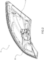
- reference number 4 indicates a vehicle light in its entirety, to which the discussion that follows will refer without, for this reason, losing generality.
- vehicle light means both a rear vehicle tail light or a front vehicle headlight, the latter also called projector, or headlamp.
- a vehicle light comprises at least one external light of the vehicle having a function of lighting and/or signalling, such as, for example, a position light, which can be a front, rear or side position light, a turn signal light, a brake light, a rear fog light, a low beam, a high beam and the like.
- a position light which can be a front, rear or side position light, a turn signal light, a brake light, a rear fog light, a low beam, a high beam and the like.
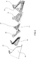
- the vehicle light 4 comprises a container body 8, usually made of polymeric material, which typically allows fixing the vehicle light 4 to the related vehicle.
- the container body 8 can have any shape and size, as well as positioning: for example, the container body 8 may not be directly associated to the bodywork or to other hardware of the associable vehicle.
- the container body 8 delimits a containment seat 12 that houses at least one light source 16 suitable to emit a light beam to be propagated outside of the vehicle light 4.
- the type of light source used is irrelevant; preferably, the light source 14 is a light emitting diode (LED) light source.
- the container body 8 can house, in said containment seat 12, intermediate support elements 18 of various optical and/or electronic components inside the vehicle light 4, in a known manner.
- the vehicle light 4 also comprises a lenticular body 20, at least partially counter-shaped with respect to the container body 8.
- the container body 8 is delimited by a first perimetral profile 24; the lenticular body 20 is in turn delimited by a second perimetral profile 28; preferably said first and second perimetral profile 24,28 are counter-shaped to each other so as to allow the coupling body of the lenticular body 20 on the container body 8.
- the lenticular body 20 is then applied to the container body 8 so as to close said containment seat 12, which houses the at least one light source 16.
- the lenticular body 20 can be outside, so as to define at least one outer wall of the vehicle light directly exposed to the atmosphere.
- the lenticular body 20 be inside a motor vehicle, so as to be housed inside a passenger compartment of the motor vehicle; this is the case, for example, of a ceiling light or a part of a dashboard of a motor vehicle.
- the lenticular body 20 closes the containment seat 12 and is suitable to transmit towards the outside of the vehicle light 4 the light beam produced by the main light source 16.
- the lenticular body 20 is made with material at least partially transparent, semi-transparent or translucent, also being able to include one or more opaque portions, so as, in any case, to allow the at least partial passage of a main light beam main emitted by said at least one main light source 16.
- the material of the lenticular body 20 is a resin such as PMMA, PC and the like.
- the light 4 comprises a substrate 32 which supports said at least one main light source 16, on the side opposite the lenticular body 20, wherein the substrate 32 comprises an outer face 36 facing the lenticular body 20 and an inner face 40, opposite the outer face 36, said at least one main light source 16 being associated on the side of the inner face 40 of the substrate 32.
- Said at least one main light source 16 is embedded in a cover layer 44, in plastic, suitable to permit the diffusion of the main light beam inside it, wherein the cover layer 44 is placed opposite the lenticular body 20 with respect to the substrate 32.
- Said cover layer 44 acts substantially as a light guide in relation to the main light beam or beams emitted by the main light source 16.
- the substrate 32 comprises at least one portion 48 transparent to the light beam suitable to transmit the main light beam towards the lenticular body 20 and, through this, outside the vehicle light 4.
- the substrate 32 comprises at least one opaque portion 52 to the main beam, adjacent to said transparent portion 48.
- Opaque portion 52 to the main light beam means a portion that does allow the main light beam to pass through, in order to form a screen or mask to the light beam itself.
- the passage of the main light beam is exclusively allowed in correspondence of said at least one transparent portion 48 and, from this, the passage of the main light beam passes through the lenticular body 20.
- the at least one transparent portion 48 defines a main light pattern of the vehicle light 4, visible from the outside of the light itself.
- the transparent portions 48 and opaque portions 52 can be arranged with each other, interpenetrating in any way so as to create any type of main light pattern.
- the substrate 32 is a sheet made of a material transparent to the beam of light emitted, and wherein said sheet is joined, on the outer face 36, to said at least one opaque portion 52.
- the substrate 32 is a flexible and/or thermoformable sheet. This makes it possible to adapt the substrate 32 to any geometry inside the vehicle light 4.
- said at least one opaque portion 52 comprises a layer opaque to the main light beam, so as to prevent the crossing of said opaque portion 52 by the light beam emitted.
- said opaque portion 52 is placed at each main light source 16 in order to conceal the presence of the main light source 16 from outside the lenticular body 20.
- the cover layer 44 comprises extractor or reflector elements 56 suitable to direct the main light beam incident upon them towards said at least one transparent portion 48.
- said extractor or reflector elements 56 are arranged on an end wall 60 of the cover layer 44 opposite the inner face 40 of the substrate 32.
- the cover layer 44 is shaped so as to achieve a total internal reflection of the main light beam, except for the transparent portions 48.
- the inner face 40 of the substrate 32 comprises reflective or diffusive surfaces 64 suitable to encourage the reflection/diffusion of the main light beam inside the cover layer 44.
- Said reflective or diffusive surfaces 64 can also be interspersed/alternated by opaque or absorbent surfaces 65 of the main light beam incident on them, in order to obtain particular optical effects.
- each main light source 16 mechanical and electrical connection means 68 of the light source 16 are arranged, suitable to mechanically fix the main light source 16 to the substrate 32 and to electrically connect the main light source 16 to an associable electricity supply of the light 4.
- said means of mechanical and electrical connection 68 of the main light source 16 comprise opaque, reflective portions and/or diffusive portions of the main light beam propagated inside the cover layer 44. In this way, even the means of mechanical and electrical connection 68 of the main light source 16 contribute to the diffusion/reflection of the main light beam inside the cover layer 44.
- the main light sources 16 fixed to the substrate 32 are of the side-LED type, so as to emit main beams having a main optical axis substantially tangent to the corresponding portion of the inner face 40 of the substrate 32.
- the cover layer 44 is fixed to the container body 8 and comprises at least one main light source 16 fixed on the inner face 40 of the substrate 32; furthermore, the vehicle light 4 comprises at least one additional light source 72, facing the outer face 36 of the substrate 32 so as to emit an additional light beam incident on said outer face 36 of the substrate 32.
- the outer face 36 of the substrate 32 in turn comprises reflective and/or diffusive portions 76 with respect to the additional light beam, to transmit the additional luminous beam towards the lenticular body 20.
- main 16 and additional 72 light source which emit the respective main and additional light beams, must not be understood as being linked to a kind of hierarchy between the light sources and corresponding light beams. These definitions are used simply to distinguish at least two different types of light beams and related light patterns emitted in output from the lenticular body 20.
- Each light pattern typically serves to identify a specific signalling and/or illumination function of the vehicle light.
- the different light patterns can be used to realise the functions of position lights, brake lights and turn signals, but also back-up lights, depth lights, fog lights, rear fog lights and lights illuminating the license plate of a motor vehicle; in addition, said light patterns can also be used for applications inside the passenger compartment, such as ceiling lights or even for illumination of parts of the instrument panel or dashboard of a motor vehicle.
- said reflective and/or diffusive portions 76 with respect to the additional beam are arranged at said opaque portions 52 to the main light beam, so as to create an additional light pattern, at least partially complementary to the main light pattern coming from the adjacent transparent portions 48 of the substrate 32.
- Said reflective and/or diffusive portions 76 with respect to the additional light beam may also be interspersed/alternated by opaque or absorbent portions 77 of the additional light beam incident on them, in order to obtain particular optical effects of the additional light pattern, such as areas of light alternating with areas of shadow, or simply areas of light of different intensities.
- Said additional light source 72 can be of any type; for example, it is an LED source.
- the additional light source 72 is mechanically and electrically connected to a corresponding support base 78.
- Said reflective and/or diffusive portions 76 constitute not only a tool for directing the additional light beam towards the lenticular body 20, but also a tool for creating a precise aesthetic effect of said additional light beam.
- the reflective and/or diffusive portions 76 are aesthetic portions that define the conformation of the additional pattern.
- said additional light source 72 is masked by a screen 80 so as not to be visible from outside the lenticular body 20.
- the screen 80 can be for example a bulkhead of any shape and size so as to prevent seeing the additional light source 72 from outside of lenticular body 20. In this way the user does not see, from the outside, the light sources that emit the light beams inside the light 4 (both the main light beam and the additional light beam) but sees only the final effect, i.e., the light beams exiting the lenticular body in the form of the preestablished main and additional patterns.
- the method of making a vehicle light according to this invention comprises the steps of:
- Figure 5a illustrates the substrate 32 on which the opaque portions 52 ( Figure 5b ) are applied, as well as the reflective or diffusive surfaces 64, and the mechanical and electrical connection means 68 ( Figures 5c-5d ), such as for example electrically conductive layers for powering the main light source 16.
- said mechanical and electrical connection means 68 such as, for example, a conductive adhesive or a soldering paste ( Figure 6e ), and a structural adhesive ( Figure 6f ) for the subsequent fixing of the main light source 16 ( Figure 6g ).
- this invention allows overcoming the drawbacks presented in the prior art.
- the light according to this invention allows obtaining any predefined light pattern and meeting all photometric specifications of the light.
- the pattern is obtained in a clear manner and it is clearly distinguishable from the outside of the light.
- the light patterns are also characterised by a significant uniformity and homogeneity of the light beam diffused outside the vehicle light.
Description
- This invention relates to a vehicle light and related manufacturing method.
- The term vehicle light means both a rear vehicle tail light or a front vehicle headlight, the latter also called projector, or headlamp.
- As is known, a vehicle light is a lighting and/or signalling device of a vehicle comprising at least one external light of the vehicle having a function of lighting and/or signalling towards the outside of a vehicle such as, for example, a position light, a turn signal light, a brake light, a rear fog light, a back-up light, a low beam, a high beam and the like.
- The vehicle light, in its most simple abstraction, comprises a container body, a lenticular body and at least one light source.
- The lenticular body is placed so as to close a mouth of the container body so as to form a housing chamber. Inside the housing chamber is arranged the light source, which can be directed so as to emit light towards the lenticular body, when electrically powered.
- The method of making a vehicle light, once the various components are assembled, must provide for the fixing and sealing of the lenticular body on the container body.
- In the art, there is an increasingly felt need to use the vehicle light not only as a tool to meet homologation needs, in order to obtain light beams that must meet particular photometric requirements, but also as a specific tool for designing the vehicle on which the light is applied.
-
EP 2 650 590 A2 discloses a vehicle light comprising a container body and a lenticular body at least partially counter-shaped to each other, wherein the container body delimits a containment seat which houses at least one main light source and the lenticular body is applied to the container body so as to close said containment seat, the lenticular body being made in transparent or semi-transparent or translucent material to a main light beam emitted by said at least one main light source, wherein the light comprises a substrate which supports said at least one main light source, the substrate comprising an outer face facing the lenticular body and an inner face, opposite the outer face, wherein said at least one main light source is embedded in a cover layer, in plastic, suitable to permit the diffusion of the main light beam inside it, wherein the substrate comprises at least one opaque portion to the main light beam. - Therefore, the luminous pattern emitted by the light has not only a signalling and/or illumination function, but also that of creating a precise desired luminous effect. This luminous effect or pattern is increasingly the leitmotif of some car manufacturers that, also thanks to the optical component of the vehicle lights, intend differentiate themselves from their competitors.
- Moreover, a need is felt to obtain optical groups able to achieve several lighting functions (such as position lights, brake lights, depth lights, back-up lights, turn signals, side markers, etc.) limiting the overall dimensions and thus the overall weight of the light itself.
- These needs are met by a vehicle light according to claim 1 and by a related method of manufacturing a vehicle light according to
claim 18. - Other embodiments of this invention are described in the dependent claims.
- Further characteristics and advantages of this invention will be more understandable from the following description of its preferred and non-limiting examples of embodiments, in which:
-
Figure 1 is a perspective view, from the front, of a vehicle light according to this invention; -
Figure 2 is a perspective view, from the rear, of the vehicle light ofFigure 1 ; -
Figure 3 is a perspective view, in separate parts, of the vehicle light ofFigure 1 ; -
Figure 4 is a sectional view of a light according to an embodiment of this invention; -
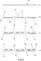
Figures 5 to 6 are schematic views, in sequence, of the assembly steps of components of a light according to this invention. - The elements, or parts of elements, in common between the embodiments described below will be indicated with the same reference numbers.
- With reference to the above figures,
reference number 4 indicates a vehicle light in its entirety, to which the discussion that follows will refer without, for this reason, losing generality. - As mentioned above, the term vehicle light means both a rear vehicle tail light or a front vehicle headlight, the latter also called projector, or headlamp.
- As is known, a vehicle light comprises at least one external light of the vehicle having a function of lighting and/or signalling, such as, for example, a position light, which can be a front, rear or side position light, a turn signal light, a brake light, a rear fog light, a low beam, a high beam and the like.
- The
vehicle light 4 comprises acontainer body 8, usually made of polymeric material, which typically allows fixing thevehicle light 4 to the related vehicle. - For the purposes of this invention, the
container body 8 can have any shape and size, as well as positioning: for example, thecontainer body 8 may not be directly associated to the bodywork or to other hardware of the associable vehicle. - According to an embodiment, the
container body 8 delimits acontainment seat 12 that houses at least onelight source 16 suitable to emit a light beam to be propagated outside of thevehicle light 4. For the purposes of this invention, the type of light source used is irrelevant; preferably, the light source 14 is a light emitting diode (LED) light source. - The
container body 8 can house, in saidcontainment seat 12,intermediate support elements 18 of various optical and/or electronic components inside thevehicle light 4, in a known manner. - The
vehicle light 4 also comprises alenticular body 20, at least partially counter-shaped with respect to thecontainer body 8. - For example, the
container body 8 is delimited by a firstperimetral profile 24; thelenticular body 20 is in turn delimited by a secondperimetral profile 28; preferably said first and secondperimetral profile lenticular body 20 on thecontainer body 8. - The
lenticular body 20 is then applied to thecontainer body 8 so as to close saidcontainment seat 12, which houses the at least onelight source 16. - For the purposes of this invention, the
lenticular body 20 can be outside, so as to define at least one outer wall of the vehicle light directly exposed to the atmosphere. - It is also possible to provide that the
lenticular body 20 be inside a motor vehicle, so as to be housed inside a passenger compartment of the motor vehicle; this is the case, for example, of a ceiling light or a part of a dashboard of a motor vehicle. - The
lenticular body 20 closes thecontainment seat 12 and is suitable to transmit towards the outside of thevehicle light 4 the light beam produced by themain light source 16. - In this regard, the
lenticular body 20 is made with material at least partially transparent, semi-transparent or translucent, also being able to include one or more opaque portions, so as, in any case, to allow the at least partial passage of a main light beam main emitted by said at least onemain light source 16. - According to possible embodiments, the material of the
lenticular body 20 is a resin such as PMMA, PC and the like. - The
light 4 comprises asubstrate 32 which supports said at least onemain light source 16, on the side opposite thelenticular body 20, wherein thesubstrate 32 comprises anouter face 36 facing thelenticular body 20 and aninner face 40, opposite theouter face 36, said at least onemain light source 16 being associated on the side of theinner face 40 of thesubstrate 32. - Said at least one
main light source 16 is embedded in acover layer 44, in plastic, suitable to permit the diffusion of the main light beam inside it, wherein thecover layer 44 is placed opposite thelenticular body 20 with respect to thesubstrate 32. - Said
cover layer 44 acts substantially as a light guide in relation to the main light beam or beams emitted by themain light source 16. - The
substrate 32 comprises at least oneportion 48 transparent to the light beam suitable to transmit the main light beam towards thelenticular body 20 and, through this, outside thevehicle light 4. - Furthermore, the
substrate 32 comprises at least oneopaque portion 52 to the main beam, adjacent to saidtransparent portion 48. -
Opaque portion 52 to the main light beam means a portion that does allow the main light beam to pass through, in order to form a screen or mask to the light beam itself. - In this way, the passage of the main light beam is exclusively allowed in correspondence of said at least one
transparent portion 48 and, from this, the passage of the main light beam passes through thelenticular body 20. - The at least one
transparent portion 48 defines a main light pattern of thevehicle light 4, visible from the outside of the light itself. - The
transparent portions 48 andopaque portions 52 can be arranged with each other, interpenetrating in any way so as to create any type of main light pattern. - According to an embodiment, the
substrate 32 is a sheet made of a material transparent to the beam of light emitted, and wherein said sheet is joined, on theouter face 36, to said at least oneopaque portion 52. - Preferably, the
substrate 32 is a flexible and/or thermoformable sheet. This makes it possible to adapt thesubstrate 32 to any geometry inside thevehicle light 4. - According to an embodiment, said at least one
opaque portion 52 comprises a layer opaque to the main light beam, so as to prevent the crossing of saidopaque portion 52 by the light beam emitted. - Preferably, said
opaque portion 52 is placed at eachmain light source 16 in order to conceal the presence of themain light source 16 from outside thelenticular body 20. - According to a possible embodiment, the
cover layer 44 comprises extractor orreflector elements 56 suitable to direct the main light beam incident upon them towards said at least onetransparent portion 48. - For example, said extractor or
reflector elements 56 are arranged on anend wall 60 of thecover layer 44 opposite theinner face 40 of thesubstrate 32. - According to an embodiment, the
cover layer 44 is shaped so as to achieve a total internal reflection of the main light beam, except for thetransparent portions 48. - Preferably, the
inner face 40 of thesubstrate 32, except for saidtransparent portions 48, comprises reflective ordiffusive surfaces 64 suitable to encourage the reflection/diffusion of the main light beam inside thecover layer 44. - Said reflective or
diffusive surfaces 64 can also be interspersed/alternated by opaque orabsorbent surfaces 65 of the main light beam incident on them, in order to obtain particular optical effects. - Between the
inner face 40 of thesubstrate 32 and eachmain light source 16 mechanical and electrical connection means 68 of thelight source 16 are arranged, suitable to mechanically fix themain light source 16 to thesubstrate 32 and to electrically connect themain light source 16 to an associable electricity supply of thelight 4. - For example, said means of mechanical and
electrical connection 68 of themain light source 16 comprise opaque, reflective portions and/or diffusive portions of the main light beam propagated inside thecover layer 44. In this way, even the means of mechanical andelectrical connection 68 of themain light source 16 contribute to the diffusion/reflection of the main light beam inside thecover layer 44. - According to a possible embodiment, the
main light sources 16 fixed to thesubstrate 32 are of the side-LED type, so as to emit main beams having a main optical axis substantially tangent to the corresponding portion of theinner face 40 of thesubstrate 32. - According to an embodiment, the
cover layer 44 is fixed to thecontainer body 8 and comprises at least one mainlight source 16 fixed on theinner face 40 of thesubstrate 32; furthermore, thevehicle light 4 comprises at least one additionallight source 72, facing theouter face 36 of thesubstrate 32 so as to emit an additional light beam incident on saidouter face 36 of thesubstrate 32. - The
outer face 36 of thesubstrate 32 in turn comprises reflective and/ordiffusive portions 76 with respect to the additional light beam, to transmit the additional luminous beam towards thelenticular body 20. - It should be clarified that the definition of the main 16 and additional 72 light source, which emit the respective main and additional light beams, must not be understood as being linked to a kind of hierarchy between the light sources and corresponding light beams. These definitions are used simply to distinguish at least two different types of light beams and related light patterns emitted in output from the
lenticular body 20. - Each light pattern typically serves to identify a specific signalling and/or illumination function of the vehicle light.
- For example, the different light patterns can be used to realise the functions of position lights, brake lights and turn signals, but also back-up lights, depth lights, fog lights, rear fog lights and lights illuminating the license plate of a motor vehicle; in addition, said light patterns can also be used for applications inside the passenger compartment, such as ceiling lights or even for illumination of parts of the instrument panel or dashboard of a motor vehicle.
- Preferably, said reflective and/or
diffusive portions 76 with respect to the additional beam are arranged at saidopaque portions 52 to the main light beam, so as to create an additional light pattern, at least partially complementary to the main light pattern coming from the adjacenttransparent portions 48 of thesubstrate 32. - Said reflective and/or
diffusive portions 76 with respect to the additional light beam may also be interspersed/alternated by opaque orabsorbent portions 77 of the additional light beam incident on them, in order to obtain particular optical effects of the additional light pattern, such as areas of light alternating with areas of shadow, or simply areas of light of different intensities. - Said additional
light source 72 can be of any type; for example, it is an LED source. - For example, the additional
light source 72 is mechanically and electrically connected to acorresponding support base 78. - Said reflective and/or
diffusive portions 76 constitute not only a tool for directing the additional light beam towards thelenticular body 20, but also a tool for creating a precise aesthetic effect of said additional light beam. - In other words, the reflective and/or
diffusive portions 76 are aesthetic portions that define the conformation of the additional pattern. - It is therefore possible to use specific surface treatments, silk-screening and similar treatments to achieve the desired graphic effect.
- Preferably, said additional
light source 72 is masked by ascreen 80 so as not to be visible from outside thelenticular body 20. - The
screen 80 can be for example a bulkhead of any shape and size so as to prevent seeing the additionallight source 72 from outside oflenticular body 20. In this way the user does not see, from the outside, the light sources that emit the light beams inside the light 4 (both the main light beam and the additional light beam) but sees only the final effect, i.e., the light beams exiting the lenticular body in the form of the preestablished main and additional patterns. - In this way these light patterns are particularly homogeneous and uniform since the emission points of the light from the respective light sources are not visible.
- Now, the method of making a vehicle light according to this invention will be described.
- In particular, the method of making a vehicle light according to this invention comprises the steps of:
- preparing a
container body 8 and alenticular body 20 at least partially counter-shaped to each other, - wherein the
container body 8 delimits acontainment seat 12 which houses at least one mainlight source 16 and thelenticular body 20 is applied to thecontainer body 8 so as to close saidcontainment seat 12, the lenticular body being made in transparent material to a main light beam emitted by said at least one mainlight source 16, - preparing a
substrate 32 which supports said at least one mainlight source 16, on the side opposite thelenticular body 20, thesubstrate 32 comprising anouter face 36 facing thelenticular body 20 and aninner face 40, opposite theouter face 36, said at least one main light source being associated on the side of theinner face 40 of thesubstrate 32, - embedding said at least one main
light source 16 in acover layer 44, in plastic, suitable to permit the diffusion of the main light beam inside it, thecover layer 44 being placed opposite thelenticular body 20 with respect to thesubstrate 32, - wherein the
substrate 32 comprises at least oneportion 48 transparent to the light beam suitable to transmit the main light beam towards thelenticular body 20 and, through this, outside thevehicle light 4, - wherein the substrate 32comprises at least one
opaque portion 52 to the main light beam, adjacent to saidtransparent portion 48 in order to allow the passage of the main light beam exclusively at saidtransparent portion 48, the at least onetransparent portion 48 defining a main light pattern of thevehicle light 4. - Some assembly stages of a vehicle light according to this invention are schematised in
Figures 5 to 6 . - In particular,
Figure 5a illustrates thesubstrate 32 on which the opaque portions 52 (Figure 5b ) are applied, as well as the reflective ordiffusive surfaces 64, and the mechanical and electrical connection means 68 (Figures 5c-5d ), such as for example electrically conductive layers for powering the mainlight source 16. - Then one proceeds, always with the deposition of said mechanical and electrical connection means 68, such as, for example, a conductive adhesive or a soldering paste (
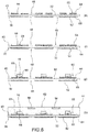
Figure 6e ), and a structural adhesive (Figure 6f ) for the subsequent fixing of the main light source 16 (Figure 6g ). - Finally, the assembly is embedded in the cover layer 44 (
Figure 6h ). - As can be appreciated from the description, this invention allows overcoming the drawbacks presented in the prior art.
- In particular, the light according to this invention allows obtaining any predefined light pattern and meeting all photometric specifications of the light.
- The pattern is obtained in a clear manner and it is clearly distinguishable from the outside of the light.
- Furthermore, it is also possible to cross one or more light patterns, for example used for different lighting functions, and overlapping them at least partially while still maintaining a clear distinguishability between them.
- The light patterns are also characterised by a significant uniformity and homogeneity of the light beam diffused outside the vehicle light.
- Therefore, thanks to this invention it is possible to obtain any light pattern, i.e., having any geometric shape, while maintaining a high energy efficiency and lighting homogeneity of the pattern itself.
- Moreover, it is possible to have a plurality of light patterns, partially or totally overlapping one another while maintaining a clear distinguishability between them if they are lit at the same time.
- A person skilled in the art, in order to satisfy contingent and specific needs, may make numerous modifications and variations to the vehicle light and methods of making vehicle lights described above, all however contained within the scope of the invention as defined by the following claims.
Claims (18)
- Vehicle light (4) comprising- a container body (8) and a lenticular body (20) at least partially counter-shaped to each other,- wherein the container body (8) delimits a containment seat (12) which houses at least one main light source (16) and the lenticular body (20) is applied to the container body (8) so as to close said containment seat (12), the lenticular body (20) being made in transparent or semi-transparent or translucent material to a main light beam emitted by said at least one main light source (16),- wherein the light (4) comprises a substrate (32) which supports said at least one main light source (16), on the side opposite the lenticular body (20), the substrate (32) comprising an outer face (36) facing the lenticular body (20) and an inner face (40), opposite the outer face (36), said at least one main light source (16) being associated on the side of the inner face (40) of the substrate (32),- wherein said at least one main light source (16) is embedded in a cover layer (44), in plastic, suitable to permit the diffusion of the main light beam inside it, the cover layer (44) being placed opposite the lenticular body (20) with respect to the substrate (32),- wherein the substrate (32) comprises at least one portion (48) transparent to the light beam suitable to transmit the main light beam towards the lenticular body (20) and, through this, outside the vehicle light (4),- wherein the substrate (32)comprises at least one opaque portion (52) to the main light beam, adjacent to said transparent portion (48) in order to allow the passage of the main light beam exclusively at said transparent portion (48), the at least one transparent portion (48) defining a main light pattern of the vehicle light (4).
- Vehicle light (4) according to claim 1, wherein the substrate (32) is a sheet made of a transparent material to the beam of light emitted, and wherein said sheet is joined, on the outer face (36), to said at least one opaque portion (52).
- Vehicle light (4) according to claim 1 or 2, where said substrate (32) is a flexible and/or thermoformable sheet.
- Vehicle light (4) according to any of the previous claims, wherein said at least one opaque portion (52) comprises a layer opaque to the main light beam, so as to prevent the crossing of said opaque portion (52) by the light beam emitted.
- Vehicle light (4) according to any of the previous claims, wherein said opaque portion (52) is placed at each main light source (16) in order to conceal the presence of the main light source (16) from outside the lenticular body (20).
- Vehicle light (4) according to any of the previous claims, wherein the cover layer (44) comprises extractor or reflector elements (56) suitable to direct the main light beam incident upon them towards said at least one transparent portion (48).
- Vehicle light (4) according to claim 6, wherein said extractor or reflector elements (56) are arranged on an end wall (60) of the cover layer (44) opposite the inner face (40) of the substrate (32).
- Vehicle light (4) according to any of the previous claims, wherein the cover layer (44) is shaped so as to achieve a total internal reflection of the main light beam, except for the transparent portions (48).
- Vehicle light (4) according to any of the earlier claims, wherein the inner face (40) of the substrate (32), except for said transparent portions (48), comprises reflective or diffusive surfaces (64) suitable to encourage the reflection/diffusion of the main light beam inside the cover layer (44).
- Vehicle light (4) according to any of the previous claims, wherein between the inner face (40) of the substrate (32) and each main light source (16) mechanical and electrical connection means (68) of the light source (16) are arranged, suitable to mechanically fix the main light source (16) to the substrate (32) and to electrically connect the main light source (16) to an associable electricity supply of the light (4).
- Vehicle light (4) according to claim 10, wherein said means of mechanical and electrical connection (68) of the main light source (16) comprise opaque, reflective portions and/or diffusive portions of the main light beam propagated inside the cover layer (44).
- Vehicle light (4) according to any of the previous claims, wherein such main light sources (16) fixed to the substrate (32) are of the side-LED type, so as to emit a main light beam having a main optical axis substantially tangent to the corresponding portion of the inner face (40) of the substrate (32).
- Vehicle light (4) according to any of the previous claims, wherein the cover layer (44) is fixed to the container body (8) and comprises at least one main light source (16) fixed to the inner face (40) of the substrate (32), and wherein the light (4) comprises at least one additional light source (72), facing the outer face (36) of the substrate (32) so as to emit an additional light beam incident on said outer face (36) of the substrate (32, the outer face (36) comprising reflective and/or diffusive portions (76) with respect to the additional light beam to transmit the additional light beam towards the lenticular body (20).
- Vehicle light (4) according to claim 13, wherein said reflective and/or diffusive portions (76) with respect to the additional beam are arranged at said opaque portions (52) to the main light beam, so as to create an additional light pattern, at least partially complementary to the main light pattern coming from the adjacent transparent portions (48) of the substrate (32).
- Vehicle light (4) according to claim 13 or 14, wherein said reflective and/or diffusive (76) portions with respect to the additional beam are interspersed/alternated by opaque or absorbent portions (77) of the additional light beam incident on them.
- Vehicle light (4) according to any of the claims 13 to 15, wherein said additional light source (72) is a LED source.
- Vehicle light (4) according to any of the claims from 13 to 16, wherein said additional light source (72) is masked by a screen (80) so as not to be visible from outside the lenticular body (20).
- Method of manufacture of a vehicle light (4) comprising the steps of:- preparing a container body and a lenticular body at least partially counter-shaped to each other,- wherein the container body (8) delimits a containment seat (12) which houses at least one main light source and the lenticular body (20) is applied to the container body (8) so as to close said containment seat (12), the lenticular body (20) being made in transparent material to a main light beam emitted by said at least one main light source (16),- preparing a substrate (32) which supports said at least one main light source (16), on the side opposite the lenticular body (20), the substrate (32) comprising an outer face (36) facing the lenticular body (20) and an inner face (40), opposite the outer face (36), said at least one main light source (16) being associated on the side of the inner face (40) of the substrate (32),- embedding said at least one main light source (16) in a cover layer (44)in plastic, suitable to permit the diffusion of the main light beam inside it, the cover layer (44) being placed opposite the lenticular body (20) with respect to the substrate (32),- wherein the substrate (32) comprises at least one portion (48) transparent to the light beam suitable to transmit the main light beam towards the lenticular body (20) and, through this, outside the vehicle light (4),- wherein the substrate (32)comprises at least one opaque portion (52) to the main light beam, adjacent to said transparent portion (48) in order to allow the passage of the main light beam exclusively at said transparent portion (48), the at least one transparent portion (48) defining a main light pattern of the vehicle light (4).
Priority Applications (1)
| Application Number | Priority Date | Filing Date | Title |
|---|---|---|---|
| PL16172050T PL3106348T3 (en) | 2015-06-16 | 2016-05-30 | Vehicle light and related manufacturing method |
Applications Claiming Priority (1)
| Application Number | Priority Date | Filing Date | Title |
|---|---|---|---|
| ITUB20151428 | 2015-06-16 |
Publications (2)
| Publication Number | Publication Date |
|---|---|
| EP3106348A1 EP3106348A1 (en) | 2016-12-21 |
| EP3106348B1 true EP3106348B1 (en) | 2018-03-14 |
Family
ID=55358039
Family Applications (1)
| Application Number | Title | Priority Date | Filing Date |
|---|---|---|---|
| EP16172050.3A Active EP3106348B1 (en) | 2015-06-16 | 2016-05-30 | Vehicle light and related manufacturing method |
Country Status (7)
| Country | Link |
|---|---|
| US (1) | US9927084B2 (en) |
| EP (1) | EP3106348B1 (en) |
| CN (1) | CN106257136B (en) |
| ES (1) | ES2673311T3 (en) |
| PL (1) | PL3106348T3 (en) |
| TR (1) | TR201808310T4 (en) |
| WO (1) | WO2017025863A2 (en) |
Families Citing this family (10)
| Publication number | Priority date | Publication date | Assignee | Title |
|---|---|---|---|---|
| FR3062452B1 (en) * | 2017-01-27 | 2019-03-29 | Peugeot Citroen Automobiles Sa | FRONT-SIDE MASK LIGHTING DEVICE LIGHTED BY IMAGE OF A COLORED PIECE |
| FR3062454B1 (en) * | 2017-01-27 | 2019-03-15 | Peugeot Citroen Automobiles Sa | 3D PATTERN MASK LIGHTING DEVICE |
| FR3062451B1 (en) * | 2017-01-27 | 2019-03-29 | Peugeot Citroen Automobiles Sa | DIAMOND TIP PATENTED MASK LIGHTING DEVICE |
| DE102017117392A1 (en) * | 2017-08-01 | 2019-02-07 | HELLA GmbH & Co. KGaA | Lighting device for vehicles |
| FR3076595B1 (en) * | 2018-01-05 | 2022-04-15 | Psa Automobiles Sa | LIGHTING AND/OR LIGHT SIGNALING DEVICE FOR A MOTOR VEHICLE |
| US11566769B2 (en) * | 2018-04-25 | 2023-01-31 | Koito Manufacturing Co., Ltd. | Vehicle lamp |
| FR3097981B1 (en) * | 2019-06-28 | 2021-07-02 | Valeo Vision | Lighting device for motor vehicle |
| CN110778987A (en) * | 2019-11-20 | 2020-02-11 | 重庆长安汽车股份有限公司 | Combined rear lamp integrating side marker lamp and rear position lamp and vehicle |
| EP3900980B1 (en) * | 2020-04-24 | 2022-12-07 | odelo GmbH | Vehicle light |
| DE102022126275A1 (en) * | 2021-10-18 | 2023-04-20 | Magna Exteriors Inc. | METHOD AND APPARATUS FOR GENERATION OF THREE-DIMENSIONAL OCCULTATION IMAGES FROM A NARROW-PROFILE ILLUMINATION ASSEMBLY |
Family Cites Families (15)
| Publication number | Priority date | Publication date | Assignee | Title |
|---|---|---|---|---|
| US3719113A (en) * | 1970-12-03 | 1973-03-06 | Gerber Garment Technology Inc | Penetrable bed used for cutting sheet material and method for treating same |
| FR2279687B1 (en) * | 1974-07-26 | 1977-01-07 | Saint Gobain | HEATED WINDOWS WITH VACUUM LAYERS |
| US4391168A (en) * | 1980-07-10 | 1983-07-05 | Gerber Garment Technology, Inc. | Method for cutting sheet material with a cutting wheel |
| CN2053000U (en) * | 1989-08-14 | 1990-02-14 | 四川省德阳市什邡教学仪器厂 | Adjustable electric heating table glass |
| IT1311417B1 (en) * | 1999-12-03 | 2002-03-12 | Bierrebi Spa | EQUIPMENT FOR CUTTING A TWO-DIMENSIONAL MATERIAL INPORTS SUITABLE FOR SHAPING. |
| KR101224265B1 (en) * | 2004-04-08 | 2013-01-18 | 페더럴-모걸 코오포레이숀 | Projector lamp headlight with chromatic aberration correction |
| ATE383544T1 (en) * | 2004-05-14 | 2008-01-15 | Fiat Ricerche | UNIT FOR PROJECTING A BEAM OF LIGHTS, AN OPTICAL DEVICE FOR THE UNIT, AND VEHICLE FRONT LIGHT DEVICE |
| US20080037267A1 (en) * | 2006-08-14 | 2008-02-14 | Converse Thomas O | Headlamp assemblies having reduced operating temperatures |
| DE102012007227A1 (en) * | 2012-04-07 | 2012-11-08 | Daimler Ag | Lighting device for vehicle lamp, has optical element having coupling point for coupling light beams emitted from light sources and decoupling point for coupling light beams |
| KR101908656B1 (en) * | 2012-04-09 | 2018-10-16 | 엘지이노텍 주식회사 | A light emitting device package |
| CN107883219B (en) * | 2012-08-10 | 2020-10-09 | Lg伊诺特有限公司 | Lighting device |
| JP6199568B2 (en) * | 2013-01-30 | 2017-09-20 | 株式会社小糸製作所 | Light emitting module |
| JP6235786B2 (en) * | 2013-03-26 | 2017-11-22 | 株式会社小糸製作所 | Cooling unit and lighting device |
| US10337688B2 (en) | 2013-03-27 | 2019-07-02 | Koito Manufacturing Co., Ltd. | Vehicle lamp |
| JP2014235817A (en) * | 2013-05-31 | 2014-12-15 | 株式会社小糸製作所 | Lighting body and lighting unit |
-
2016
- 2016-05-30 EP EP16172050.3A patent/EP3106348B1/en active Active
- 2016-05-30 PL PL16172050T patent/PL3106348T3/en unknown
- 2016-05-30 ES ES16172050.3T patent/ES2673311T3/en active Active
- 2016-05-30 TR TR2018/08310T patent/TR201808310T4/en unknown
- 2016-06-15 US US15/182,800 patent/US9927084B2/en active Active
- 2016-06-16 CN CN201610429412.6A patent/CN106257136B/en active Active
- 2016-08-03 WO PCT/IB2016/054678 patent/WO2017025863A2/en unknown
Non-Patent Citations (1)
| Title |
|---|
| None * |
Also Published As
| Publication number | Publication date |
|---|---|
| ES2673311T3 (en) | 2018-06-21 |
| CN106257136A (en) | 2016-12-28 |
| WO2017025863A3 (en) | 2017-06-29 |
| US20160369964A1 (en) | 2016-12-22 |
| TR201808310T4 (en) | 2018-07-23 |
| WO2017025863A2 (en) | 2017-02-16 |
| EP3106348A1 (en) | 2016-12-21 |
| CN106257136B (en) | 2020-05-08 |
| US9927084B2 (en) | 2018-03-27 |
| PL3106348T3 (en) | 2018-08-31 |
Similar Documents
| Publication | Publication Date | Title |
|---|---|---|
| EP3106348B1 (en) | Vehicle light and related manufacturing method | |
| US11235699B2 (en) | Illumination module for vehicle | |
| US10711970B2 (en) | Lamp and vehicle having same | |
| KR102036223B1 (en) | Light assembly to illuminate the emblem | |
| US9416934B2 (en) | Light source module of lamp for vehicle | |
| US20190170317A1 (en) | Light device, especially signal lamp, for motor vehicles | |
| JP2014101057A (en) | Lighting fixture for vehicle including bifurcation light guide lens | |
| US8387257B2 (en) | Vehicle interior panel and method to manufacture | |
| CN106195847B (en) | Mood light for vehicle | |
| CN108361651B (en) | Lighting device with light guide mounted on support integrated with transparent magnifying screen | |
| JP2001283617A (en) | Lamp for vehicle | |
| JP2014175204A (en) | Lighting fixture | |
| CN111795361B (en) | Vehicle part with a chromium-based reflective coating that is at least partially transparent to light | |
| CN209191780U (en) | Vehicle lighting assembly | |
| US7168838B2 (en) | Vehicle lamp | |
| KR20160035011A (en) | Lighting system, in particular for a motor vehicle lighting member, comprising integrated leds | |
| CN106662303B (en) | Lighting and/or signalling device for generating uniform light on a screen | |
| US10422502B2 (en) | Motor vehicle lamp and motor vehicle | |
| CN108361648B (en) | Lighting device comprising a shade with a 3D pattern | |
| JP4370259B2 (en) | Vehicle lamp and method for displaying different signal patterns of a vehicle lamp | |
| KR200483959Y1 (en) | Lamp for vehicle | |
| JP2019023992A (en) | Light-emitting device for automobile | |
| CN220688848U (en) | Optical module, lighting device and vehicle | |
| JP7223532B2 (en) | Light-emitting devices for road lighting, signaling or interior lighting | |
| KR20180057405A (en) | Lamp for vehicle |
Legal Events
| Date | Code | Title | Description |
|---|---|---|---|
| PUAI | Public reference made under article 153(3) epc to a published international application that has entered the european phase |
Free format text: ORIGINAL CODE: 0009012 |
|
| AK | Designated contracting states |
Kind code of ref document: A1 Designated state(s): AL AT BE BG CH CY CZ DE DK EE ES FI FR GB GR HR HU IE IS IT LI LT LU LV MC MK MT NL NO PL PT RO RS SE SI SK SM TR |
|
| AX | Request for extension of the european patent |
Extension state: BA ME |
|
| 17P | Request for examination filed |
Effective date: 20170616 |
|
| RBV | Designated contracting states (corrected) |
Designated state(s): AL AT BE BG CH CY CZ DE DK EE ES FI FR GB GR HR HU IE IS IT LI LT LU LV MC MK MT NL NO PL PT RO RS SE SI SK SM TR |
|
| RIC1 | Information provided on ipc code assigned before grant |
Ipc: F21S 8/10 20060101ALI20170721BHEP Ipc: F21V 8/00 20060101ALI20170721BHEP Ipc: H01L 27/00 20060101ALI20170721BHEP Ipc: F21W 101/14 20060101ALN20170721BHEP Ipc: B60Q 1/26 20060101AFI20170721BHEP Ipc: F21Y 111/00 20160101ALN20170721BHEP |
|
| GRAP | Despatch of communication of intention to grant a patent |
Free format text: ORIGINAL CODE: EPIDOSNIGR1 |
|
| RIC1 | Information provided on ipc code assigned before grant |
Ipc: H01L 27/00 20060101ALI20170915BHEP Ipc: F21S 8/10 20060101ALI20170915BHEP Ipc: B60Q 1/26 20060101AFI20170915BHEP Ipc: F21Y 111/00 20160101ALN20170915BHEP Ipc: F21W 101/14 20060101ALN20170915BHEP Ipc: F21V 8/00 20060101ALI20170915BHEP |
|
| INTG | Intention to grant announced |
Effective date: 20171006 |
|
| GRAS | Grant fee paid |
Free format text: ORIGINAL CODE: EPIDOSNIGR3 |
|
| GRAA | (expected) grant |
Free format text: ORIGINAL CODE: 0009210 |
|
| AK | Designated contracting states |
Kind code of ref document: B1 Designated state(s): AL AT BE BG CH CY CZ DE DK EE ES FI FR GB GR HR HU IE IS IT LI LT LU LV MC MK MT NL NO PL PT RO RS SE SI SK SM TR |
|
| REG | Reference to a national code |
Ref country code: GB Ref legal event code: FG4D |
|
| REG | Reference to a national code |
Ref country code: CH Ref legal event code: EP Ref country code: AT Ref legal event code: REF Ref document number: 978529 Country of ref document: AT Kind code of ref document: T Effective date: 20180315 |
|
| REG | Reference to a national code |
Ref country code: IE Ref legal event code: FG4D |
|
| REG | Reference to a national code |
Ref country code: DE Ref legal event code: R096 Ref document number: 602016001961 Country of ref document: DE |
|
| REG | Reference to a national code |
Ref country code: FR Ref legal event code: PLFP Year of fee payment: 3 |
|
| REG | Reference to a national code |
Ref country code: ES Ref legal event code: FG2A Ref document number: 2673311 Country of ref document: ES Kind code of ref document: T3 Effective date: 20180621 |
|
| REG | Reference to a national code |
Ref country code: NL Ref legal event code: MP Effective date: 20180314 |
|
| REG | Reference to a national code |
Ref country code: LT Ref legal event code: MG4D |
|
| PG25 | Lapsed in a contracting state [announced via postgrant information from national office to epo] |
Ref country code: FI Free format text: LAPSE BECAUSE OF FAILURE TO SUBMIT A TRANSLATION OF THE DESCRIPTION OR TO PAY THE FEE WITHIN THE PRESCRIBED TIME-LIMIT Effective date: 20180314 Ref country code: NO Free format text: LAPSE BECAUSE OF FAILURE TO SUBMIT A TRANSLATION OF THE DESCRIPTION OR TO PAY THE FEE WITHIN THE PRESCRIBED TIME-LIMIT Effective date: 20180614 Ref country code: HR Free format text: LAPSE BECAUSE OF FAILURE TO SUBMIT A TRANSLATION OF THE DESCRIPTION OR TO PAY THE FEE WITHIN THE PRESCRIBED TIME-LIMIT Effective date: 20180314 Ref country code: LT Free format text: LAPSE BECAUSE OF FAILURE TO SUBMIT A TRANSLATION OF THE DESCRIPTION OR TO PAY THE FEE WITHIN THE PRESCRIBED TIME-LIMIT Effective date: 20180314 Ref country code: CY Free format text: LAPSE BECAUSE OF FAILURE TO SUBMIT A TRANSLATION OF THE DESCRIPTION OR TO PAY THE FEE WITHIN THE PRESCRIBED TIME-LIMIT Effective date: 20180314 |
|
| REG | Reference to a national code |
Ref country code: AT Ref legal event code: MK05 Ref document number: 978529 Country of ref document: AT Kind code of ref document: T Effective date: 20180314 |
|
| PG25 | Lapsed in a contracting state [announced via postgrant information from national office to epo] |
Ref country code: BG Free format text: LAPSE BECAUSE OF FAILURE TO SUBMIT A TRANSLATION OF THE DESCRIPTION OR TO PAY THE FEE WITHIN THE PRESCRIBED TIME-LIMIT Effective date: 20180614 Ref country code: GR Free format text: LAPSE BECAUSE OF FAILURE TO SUBMIT A TRANSLATION OF THE DESCRIPTION OR TO PAY THE FEE WITHIN THE PRESCRIBED TIME-LIMIT Effective date: 20180615 Ref country code: SE Free format text: LAPSE BECAUSE OF FAILURE TO SUBMIT A TRANSLATION OF THE DESCRIPTION OR TO PAY THE FEE WITHIN THE PRESCRIBED TIME-LIMIT Effective date: 20180314 Ref country code: LV Free format text: LAPSE BECAUSE OF FAILURE TO SUBMIT A TRANSLATION OF THE DESCRIPTION OR TO PAY THE FEE WITHIN THE PRESCRIBED TIME-LIMIT Effective date: 20180314 Ref country code: RS Free format text: LAPSE BECAUSE OF FAILURE TO SUBMIT A TRANSLATION OF THE DESCRIPTION OR TO PAY THE FEE WITHIN THE PRESCRIBED TIME-LIMIT Effective date: 20180314 |
|
| PG25 | Lapsed in a contracting state [announced via postgrant information from national office to epo] |
Ref country code: NL Free format text: LAPSE BECAUSE OF FAILURE TO SUBMIT A TRANSLATION OF THE DESCRIPTION OR TO PAY THE FEE WITHIN THE PRESCRIBED TIME-LIMIT Effective date: 20180314 Ref country code: EE Free format text: LAPSE BECAUSE OF FAILURE TO SUBMIT A TRANSLATION OF THE DESCRIPTION OR TO PAY THE FEE WITHIN THE PRESCRIBED TIME-LIMIT Effective date: 20180314 Ref country code: RO Free format text: LAPSE BECAUSE OF FAILURE TO SUBMIT A TRANSLATION OF THE DESCRIPTION OR TO PAY THE FEE WITHIN THE PRESCRIBED TIME-LIMIT Effective date: 20180314 Ref country code: AL Free format text: LAPSE BECAUSE OF FAILURE TO SUBMIT A TRANSLATION OF THE DESCRIPTION OR TO PAY THE FEE WITHIN THE PRESCRIBED TIME-LIMIT Effective date: 20180314 |
|
| PG25 | Lapsed in a contracting state [announced via postgrant information from national office to epo] |
Ref country code: SK Free format text: LAPSE BECAUSE OF FAILURE TO SUBMIT A TRANSLATION OF THE DESCRIPTION OR TO PAY THE FEE WITHIN THE PRESCRIBED TIME-LIMIT Effective date: 20180314 Ref country code: SM Free format text: LAPSE BECAUSE OF FAILURE TO SUBMIT A TRANSLATION OF THE DESCRIPTION OR TO PAY THE FEE WITHIN THE PRESCRIBED TIME-LIMIT Effective date: 20180314 Ref country code: AT Free format text: LAPSE BECAUSE OF FAILURE TO SUBMIT A TRANSLATION OF THE DESCRIPTION OR TO PAY THE FEE WITHIN THE PRESCRIBED TIME-LIMIT Effective date: 20180314 |
|
| REG | Reference to a national code |
Ref country code: DE Ref legal event code: R097 Ref document number: 602016001961 Country of ref document: DE |
|
| PG25 | Lapsed in a contracting state [announced via postgrant information from national office to epo] |
Ref country code: PT Free format text: LAPSE BECAUSE OF FAILURE TO SUBMIT A TRANSLATION OF THE DESCRIPTION OR TO PAY THE FEE WITHIN THE PRESCRIBED TIME-LIMIT Effective date: 20180716 |
|
| RIC2 | Information provided on ipc code assigned after grant |
Ipc: F21S 8/10 20181130ALI20170915BHEP Ipc: H01L 27/00 20060101ALI20170915BHEP Ipc: F21Y 111/00 20160101ALN20170915BHEP Ipc: F21V 8/00 20060101ALI20170915BHEP Ipc: B60Q 1/26 20060101AFI20170915BHEP Ipc: F21W 101/14 20181130ALN20170915BHEP |
|
| REG | Reference to a national code |
Ref country code: CH Ref legal event code: PK Free format text: RETTIFICHE |
|
| PLBE | No opposition filed within time limit |
Free format text: ORIGINAL CODE: 0009261 |
|
| STAA | Information on the status of an ep patent application or granted ep patent |
Free format text: STATUS: NO OPPOSITION FILED WITHIN TIME LIMIT |
|
| REG | Reference to a national code |
Ref country code: BE Ref legal event code: MM Effective date: 20180531 |
|
| PG25 | Lapsed in a contracting state [announced via postgrant information from national office to epo] |
Ref country code: MC Free format text: LAPSE BECAUSE OF FAILURE TO SUBMIT A TRANSLATION OF THE DESCRIPTION OR TO PAY THE FEE WITHIN THE PRESCRIBED TIME-LIMIT Effective date: 20180314 Ref country code: DK Free format text: LAPSE BECAUSE OF FAILURE TO SUBMIT A TRANSLATION OF THE DESCRIPTION OR TO PAY THE FEE WITHIN THE PRESCRIBED TIME-LIMIT Effective date: 20180314 |
|
| REG | Reference to a national code |
Ref country code: CH Ref legal event code: PK Free format text: RETTIFICHE |
|
| RIC2 | Information provided on ipc code assigned after grant |
Ipc: F21W 101/14 20060101ALN20170915BHEP Ipc: F21S 8/10 20060101ALI20170915BHEP Ipc: F21Y 111/00 20160101ALN20170915BHEP Ipc: F21V 8/00 20060101ALI20170915BHEP Ipc: H01L 27/00 20060101ALI20170915BHEP Ipc: B60Q 1/26 20060101AFI20170915BHEP |
|
| 26N | No opposition filed |
Effective date: 20181217 |
|
| REG | Reference to a national code |
Ref country code: IE Ref legal event code: MM4A |
|
| PG25 | Lapsed in a contracting state [announced via postgrant information from national office to epo] |
Ref country code: SI Free format text: LAPSE BECAUSE OF FAILURE TO SUBMIT A TRANSLATION OF THE DESCRIPTION OR TO PAY THE FEE WITHIN THE PRESCRIBED TIME-LIMIT Effective date: 20180314 |
|
| PG25 | Lapsed in a contracting state [announced via postgrant information from national office to epo] |
Ref country code: LU Free format text: LAPSE BECAUSE OF NON-PAYMENT OF DUE FEES Effective date: 20180530 |
|
| PG25 | Lapsed in a contracting state [announced via postgrant information from national office to epo] |
Ref country code: IE Free format text: LAPSE BECAUSE OF NON-PAYMENT OF DUE FEES Effective date: 20180530 |
|
| PG25 | Lapsed in a contracting state [announced via postgrant information from national office to epo] |
Ref country code: BE Free format text: LAPSE BECAUSE OF NON-PAYMENT OF DUE FEES Effective date: 20180531 |
|
| REG | Reference to a national code |
Ref country code: CH Ref legal event code: PL |
|
| PG25 | Lapsed in a contracting state [announced via postgrant information from national office to epo] |
Ref country code: MT Free format text: LAPSE BECAUSE OF NON-PAYMENT OF DUE FEES Effective date: 20180530 Ref country code: CH Free format text: LAPSE BECAUSE OF NON-PAYMENT OF DUE FEES Effective date: 20190531 Ref country code: LI Free format text: LAPSE BECAUSE OF NON-PAYMENT OF DUE FEES Effective date: 20190531 |
|
| PG25 | Lapsed in a contracting state [announced via postgrant information from national office to epo] |
Ref country code: MK Free format text: LAPSE BECAUSE OF NON-PAYMENT OF DUE FEES Effective date: 20180314 Ref country code: HU Free format text: LAPSE BECAUSE OF FAILURE TO SUBMIT A TRANSLATION OF THE DESCRIPTION OR TO PAY THE FEE WITHIN THE PRESCRIBED TIME-LIMIT; INVALID AB INITIO Effective date: 20160530 |
|
| PG25 | Lapsed in a contracting state [announced via postgrant information from national office to epo] |
Ref country code: IS Free format text: LAPSE BECAUSE OF FAILURE TO SUBMIT A TRANSLATION OF THE DESCRIPTION OR TO PAY THE FEE WITHIN THE PRESCRIBED TIME-LIMIT Effective date: 20180714 |
|
| GBPC | Gb: european patent ceased through non-payment of renewal fee |
Effective date: 20200530 |
|
| PG25 | Lapsed in a contracting state [announced via postgrant information from national office to epo] |
Ref country code: GB Free format text: LAPSE BECAUSE OF NON-PAYMENT OF DUE FEES Effective date: 20200530 |
|
| P01 | Opt-out of the competence of the unified patent court (upc) registered |
Effective date: 20230526 |
|
| PGFP | Annual fee paid to national office [announced via postgrant information from national office to epo] |
Ref country code: IT Payment date: 20230420 Year of fee payment: 8 Ref country code: FR Payment date: 20230420 Year of fee payment: 8 Ref country code: ES Payment date: 20230601 Year of fee payment: 8 Ref country code: DE Payment date: 20230419 Year of fee payment: 8 Ref country code: CZ Payment date: 20230421 Year of fee payment: 8 |
|
| PGFP | Annual fee paid to national office [announced via postgrant information from national office to epo] |
Ref country code: TR Payment date: 20230428 Year of fee payment: 8 Ref country code: PL Payment date: 20230424 Year of fee payment: 8 |