EP3043152A1 - Glow ring for instrument panel - Google Patents
Glow ring for instrument panel Download PDFInfo
- Publication number
- EP3043152A1 EP3043152A1 EP16150885.8A EP16150885A EP3043152A1 EP 3043152 A1 EP3043152 A1 EP 3043152A1 EP 16150885 A EP16150885 A EP 16150885A EP 3043152 A1 EP3043152 A1 EP 3043152A1
- Authority
- EP
- European Patent Office
- Prior art keywords
- light
- light guide
- leg
- guide assembly
- prismatic
- Prior art date
- Legal status (The legal status is an assumption and is not a legal conclusion. Google has not performed a legal analysis and makes no representation as to the accuracy of the status listed.)
- Granted
Links
- 238000005286 illumination Methods 0.000 claims abstract description 13
- 239000000758 substrate Substances 0.000 claims description 7
- 239000013536 elastomeric material Substances 0.000 claims description 5
- 230000000712 assembly Effects 0.000 description 5
- 238000000429 assembly Methods 0.000 description 5
- 230000005540 biological transmission Effects 0.000 description 3
- 238000000034 method Methods 0.000 description 2
- 238000010276 construction Methods 0.000 description 1
- 238000004519 manufacturing process Methods 0.000 description 1
- 238000012986 modification Methods 0.000 description 1
- 230000004048 modification Effects 0.000 description 1
- 238000000465 moulding Methods 0.000 description 1
Images


Classifications
-
- B—PERFORMING OPERATIONS; TRANSPORTING
- B60—VEHICLES IN GENERAL
- B60Q—ARRANGEMENT OF SIGNALLING OR LIGHTING DEVICES, THE MOUNTING OR SUPPORTING THEREOF OR CIRCUITS THEREFOR, FOR VEHICLES IN GENERAL
- B60Q3/00—Arrangement of lighting devices for vehicle interiors; Lighting devices specially adapted for vehicle interiors
- B60Q3/10—Arrangement of lighting devices for vehicle interiors; Lighting devices specially adapted for vehicle interiors for dashboards
- B60Q3/12—Arrangement of lighting devices for vehicle interiors; Lighting devices specially adapted for vehicle interiors for dashboards lighting onto the surface to be illuminated
-
- B—PERFORMING OPERATIONS; TRANSPORTING
- B60—VEHICLES IN GENERAL
- B60Q—ARRANGEMENT OF SIGNALLING OR LIGHTING DEVICES, THE MOUNTING OR SUPPORTING THEREOF OR CIRCUITS THEREFOR, FOR VEHICLES IN GENERAL
- B60Q3/00—Arrangement of lighting devices for vehicle interiors; Lighting devices specially adapted for vehicle interiors
- B60Q3/10—Arrangement of lighting devices for vehicle interiors; Lighting devices specially adapted for vehicle interiors for dashboards
- B60Q3/14—Arrangement of lighting devices for vehicle interiors; Lighting devices specially adapted for vehicle interiors for dashboards lighting through the surface to be illuminated
-
- B—PERFORMING OPERATIONS; TRANSPORTING
- B60—VEHICLES IN GENERAL
- B60Q—ARRANGEMENT OF SIGNALLING OR LIGHTING DEVICES, THE MOUNTING OR SUPPORTING THEREOF OR CIRCUITS THEREFOR, FOR VEHICLES IN GENERAL
- B60Q3/00—Arrangement of lighting devices for vehicle interiors; Lighting devices specially adapted for vehicle interiors
- B60Q3/60—Arrangement of lighting devices for vehicle interiors; Lighting devices specially adapted for vehicle interiors characterised by optical aspects
- B60Q3/62—Arrangement of lighting devices for vehicle interiors; Lighting devices specially adapted for vehicle interiors characterised by optical aspects using light guides
- B60Q3/66—Arrangement of lighting devices for vehicle interiors; Lighting devices specially adapted for vehicle interiors characterised by optical aspects using light guides for distributing light among several lighting devices
-
- F—MECHANICAL ENGINEERING; LIGHTING; HEATING; WEAPONS; BLASTING
- F21—LIGHTING
- F21S—NON-PORTABLE LIGHTING DEVICES; SYSTEMS THEREOF; VEHICLE LIGHTING DEVICES SPECIALLY ADAPTED FOR VEHICLE EXTERIORS
- F21S43/00—Signalling devices specially adapted for vehicle exteriors, e.g. brake lamps, direction indicator lights or reversing lights
-
- F—MECHANICAL ENGINEERING; LIGHTING; HEATING; WEAPONS; BLASTING
- F21—LIGHTING
- F21V—FUNCTIONAL FEATURES OR DETAILS OF LIGHTING DEVICES OR SYSTEMS THEREOF; STRUCTURAL COMBINATIONS OF LIGHTING DEVICES WITH OTHER ARTICLES, NOT OTHERWISE PROVIDED FOR
- F21V23/00—Arrangement of electric circuit elements in or on lighting devices
- F21V23/04—Arrangement of electric circuit elements in or on lighting devices the elements being switches
-
- F—MECHANICAL ENGINEERING; LIGHTING; HEATING; WEAPONS; BLASTING
- F21—LIGHTING
- F21V—FUNCTIONAL FEATURES OR DETAILS OF LIGHTING DEVICES OR SYSTEMS THEREOF; STRUCTURAL COMBINATIONS OF LIGHTING DEVICES WITH OTHER ARTICLES, NOT OTHERWISE PROVIDED FOR
- F21V7/00—Reflectors for light sources
- F21V7/04—Optical design
-
- G—PHYSICS
- G01—MEASURING; TESTING
- G01D—MEASURING NOT SPECIALLY ADAPTED FOR A SPECIFIC VARIABLE; ARRANGEMENTS FOR MEASURING TWO OR MORE VARIABLES NOT COVERED IN A SINGLE OTHER SUBCLASS; TARIFF METERING APPARATUS; MEASURING OR TESTING NOT OTHERWISE PROVIDED FOR
- G01D11/00—Component parts of measuring arrangements not specially adapted for a specific variable
- G01D11/28—Structurally-combined illuminating devices
-
- F—MECHANICAL ENGINEERING; LIGHTING; HEATING; WEAPONS; BLASTING
- F21—LIGHTING
- F21W—INDEXING SCHEME ASSOCIATED WITH SUBCLASSES F21K, F21L, F21S and F21V, RELATING TO USES OR APPLICATIONS OF LIGHTING DEVICES OR SYSTEMS
- F21W2107/00—Use or application of lighting devices on or in particular types of vehicles
- F21W2107/10—Use or application of lighting devices on or in particular types of vehicles for land vehicles
Definitions
- Light emitting assemblies for automotive and other applications are generally well known. Regardless there is a continuous need for improvement in the uniformity of light transmission through such assemblies for aesthetic, safety and efficiency reasons. Specifically, there has been a continuing trade-off between the uniformity of light transmission through such assemblies and the number and location of the necessary light emitting diodes (LEDs) to illuminate such assemblies. These trade-offs have resulted in instrument panels that use multiple LEDs, and have "bright spots" in the illumination medium where too much illumination is emitted, and dark or dull spots, where not enough illumination is emitted. In addition, there has been a problem with light being mischanneled through locator tabs or other structures where the light is lost, thereby lowering the intensity of the light that is emitted from light emitting assemblies. This may affect the aesthetics of the instrument panel and, in extreme cases, may affect safety issues related to the instrument panel, such as, for example, a vehicle instrument panel.
- LEDs light emitting diodes
- a light emitting assembly for instrument panel illumination, such as, for example, a vehicle instrument panel.
- the assembly may include a light guide assembly having opposed first and second surfaces separated by a sidewall extending substantially unbroken therebetween to define a light guide assembly body having a width and a light guide body index of refraction.
- the light guide assembly is made from any suitable transparent, moldable, elastomeric material having a predetermined index of refraction.
- At least one light transmissive leg extends from the second surface of the light guide assembly body.
- Each light transmissive leg has a first end and a second end separated by a length to define a leg body, and the first end has a light input surface along an edge of the leg.
- the light input surface is in close proximity to at least one of the diodes, and the light emitting diode emit an incident light ray at an angle of incidence to said light input surface
- the leg has in index of refraction for refracting the incident light ray to form a refractive light ray along the light transmissive leg.
- a prismatic Y shaped light reflective structure Integral with the light guide assembly body and formed integrally at an intersection of the second end of the leg, is a prismatic Y shaped light reflective structure at the first surface of the light guide body.
- the prismatic Y shaped light reflective structure forms an angle of reflection surface at said intersection with said first surface within the width of the body of a predetermined angle of reflection to reflect the refractive light ray from the leg to the second surface of the light guide assembly body.
- the reflected light ray is then refracted substantially uniformly through said light guide assembly body along the first and second body surfaces to produce substantially uniform illumination of said light guide assembly.
- the light emitting assembly need not be limited to use in instrument panels. There is also a need for any number of lighting applications, especially in automotive applications. Examples include, but are not limited to, vanity mirrors, interior lighting, lighting controls, switches, door lights, reading lights, accent lights, steering wheels, radios/infotainment system lighting, etc.
- FIGURES 1 and 2 there is disclosed therein a basic geometry on one aspect of a light guide useful in one embodiment of a light emitting assembly.
- FIGURE 1 is an exploded schematic view of an instrument panel 10, such as an instrument panel, according to one aspect of the present disclosure.
- the instrument panel has a visor 12 equipped with instrument apertures 14, 16 and 18, to accommodate various instrument gauges(such as speedometer, tachometer, etc) and other controls, systems or radio or infotainment systems and controls.
- the instrument visor is further equipped with aperture attachment flanges 20, 21,22 and 23, to permit the assembled instrument panel to be secured into place in the vehicle interior.
- the instrument panel may also include a transparent substrate overlying at least the visor body aperture for viewing said gauge. Suitable transparent substrates include plates, plastic, film or any other medium.
- a light guide assembly 32 shown as a glow ring, has legs 34, 36, 38, and 40 as well as locator tabs 42, 44, 46 and 48. As will be discussed in greater detail regarding Figures 3 through 7 , the light guide assembly may be any shape, but is here shown as a ring structure.
- the light guide assembly is a transparent, moldable, elastomeric material having a predetermined index of refraction that is suitable for a "one shot" molding process for convenience of manufacture.
- An applique 50 has instrument detents 49 and 51, together with aperture 47 to accommodate instrument gauges and the radio or infotainment system of an exemplary vehicle instrument panel.
- the appliqué is equipped with apertures52, 54, 56, 58, at detent 49 and apertures 60, 62, 64, and 66 at detent 51, shown as slotted arcuate apertures, to permit the legs of the glow ring to pass therethrough, and to interact with the locator tabs on the glow ring so that during assembly, the glow ring in fitted through the appliqué slots and turned to engage the locator tabs to secure the glow ring into place in the appliqué.
- a light housing 68 has instrument recesses 70 and 72 as well as a cut out 73 to accommodate the radio/infotainment system.
- the light housing has glow ring apertures 74,76, 78, and 80 at recess 70, and glow ring apertures 82, 84, 86, and 88 at recess 72.
- the legs of the glow ring extend through these apertures when the instrument panel is assembled, so that the glow ring legs may be in close proximity to light emitting diodes on printed circuit board 90.
- Printed circuit board includes circuits 92 and 94 and is electrically connected to a vehicle electrical system for powering all the instrument gauges of the vehicle.
- the circuit board includes light emitting diodes (LEDs) 96, 98, 100, 102, 104, 106 108 and 110 as indicated for emitting light to the glow ring as will be hereafter be described.
- the LEDs are positioned on the circuit board in any configuration as to be complementarily accessible to the legs of the glow ring.
- FIGURE 2 is a detailed sectional view of an assembled vehicle instrument panel showing the glow ring (or light guide assembly) in place.
- the light guide assembly (glow ring) is located in close proximity to the gauge detent and the gauge aperture so that, when powered, will substantially uniformly illuminate the gauge with which it is associated.
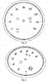
- FIGURE 3 is a schematic representation of one configuration of a light guide assembly 32 showing a top plan view.
- the light guide assembly in this embodiment is depicted as circular, and has a center 109, a diameter 111 to an inner periphery 112, all of which are subject to design choice and requirements of application.
- the light guide assembly has a ring width 113, and an outer periphery 114 and is situated in close proximity to LEDs on a circuit. Note that the legs of the light guide assembly are not depicted in this view so that the positioning of the light guide assembly relative to the LEDs can be clearly shown.
- FIGURE 4 is a schematic representation of the light guide assembly of FIGURE 3 , showing the sidewall 115 extending substantially unbroken between a first or top surface 116 and second or bottom surface 117 to define a body 118 with a thickness 119. Note that the light guide assembly thickness is about half the width 113. Again, the legs are not shown in this view simply to show the location of the light guide assembly in close proximity to the LEDs on the circuit.
- FIGURE 5 is a detailed side view of the light guide assembly 32 showing a leg 34.
- the geometry shown is optimized to reduce so called hot spots in the visible area of the glow ring by the angle of surface 162.
- Any leg of the glow ring may be understood to have similar characteristics and location relative to an LED as will described in relation to leg 34.
- Leg has a first end 35 and a second end 37 separated by a length 33.
- the leg has a surface 31, and a light input surface 39 in close proximity, or directly proximal, to a LED.
- the second end of the leg forms a prismatic Y shaped reflective structure 120 integral with the body of the light guide assembly at its first or top surface.
- the prismatic Y shaped light reflective structure is formed to create a reflective surface angle 162 at, along or within the first surface of the light guide assembly of from about 6 to about 10 degrees relative to horizontal
- the glow ring assembly body has an index of refraction as does the leg. These indices of refraction may be the same or different, depending upon design needs.
- the LED emits an incident light ray 122 which strikes the light input surface at an angle of incidence 123.
- the leg which has a refractive index, refracts the incoming light at a refraction angle 124 as a refraction light ray 125.
- the refraction ray strikes the prismatic reflective surface 126 at an angle of incidence, and is reflected at an angle of reflection 127 to the second (or bottom) surface of the ring.
- the light ray is then refracted along path 128 through the body portion of the light guide assembly, being reflected between the first surface and the second surface of the light guide assembly body.
- the body glows and the light is emitted substantially uniformly along the body of the light guide assembly. It is especially important to control the reflection and refraction of the light as it moves through the light guide assembly to minimize any "bright spots", especially at the first surface where the refractive light ray strikes the first surface of the light guide assembly body, and also to minimize any "dark spots” that may occur especially at the locator tabs where the light may be diffused and thereby lost for useful illumination purposes.
- FIGURE 6 there is shown a detailed perspective top view of a portion of the first surface and leg intersection showing the basic Y shaped glow ring structure which diverts light into both right and left channels of the glow ring to avoid dark spots at locales distant from the light source.
- the prismatic Y shaped light reflective structure includes first and second concave arcuate surfaces 142, 144, respectively, opposed to each other by an angle ⁇ and intersecting with each other at first end apex 146 and intersecting the light guide emitting assembly body at a second end 148 and 150, respectively.
- the prismatic Y shaped reflective structure has a top surface 152 intersecting the concave arcuate surfaces 142 and 144 by first and second upwardly inclined arcuate land surfaces 154 and 156, respectively.
- the top surface is concavely arcuate and intersects light guide emitting assembly first surface at first and second arcuate reflective land surfaces 158 and 160, respectively, and are separated from each other by a third arcuate reflective land surface 162, which also intersects with the first surface of the light guide assembly body.
- Land surface 162 minimizes so called "hot spots" or areas wherein light is perceived to be brighter in the glow ring than in other areas of the glow ring.
- FIGURE 7A and 7B shows another embodiment of the light guide assembly 32.
- FIGURE 7A shows the light guide assembly from a top plan perspective showing the prismatic Y shaped reflective structure as well as the locator tabs 42, 44, 46 and 48 in close proximity to the prismatic Y shaped reflective structure 120.
- the light guide assembly is formed of a transparent, moldable elastomeric material having a predetermined index of refraction.
- the light guide assembly is made in a one shot mold process to minimize costs, and ensure that the prismatic reflective structure is formed at each intersection of the legs with the body of the light guide assembly along, at or near the first surface of the assembly.
- the locator tabs have traditionally been associated with "light bleed", wherein light is channel to the locators, leaks from the substrate, and is thereby lost to the glow ring. As shown in FIGURE 7B , it has been determined that positioning the locator tabs in a plane 164 below the plane of the glow ring virtually eliminates the light bleed phenomenon. By positioning the locator tabs thus, light transmission through the glow ring substrate is substantially uniform, thereby essentially eliminating hot spots or dark spots.
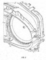
- FIGURE 8 is a detailed view of the glow ring in place in an instrument panel showing the substantially uniform illumination of the glow ring. Such uniform illumination is more aesthetically pleasing, and presents a very clear outline of the gauge and what is happening on the gauge.
- FIGURE 9 is a perspective side view of the illuminating glow ring in an instrument panel setting. As seen therein, there is substantially uniform lighting with substantially no bright spots or dark spots.
- the light emitting guide assembly is shown in this description as illuminating a vehicle instrument panel, However, it is apparent that the light guide assembly may also find application in vanity lights, vanity mirrors, interior lighting, lighting controls, switches, door lights, reading lights, accent lights, steering wheels, radios/infotainment system lighting, etc.
Landscapes
- Engineering & Computer Science (AREA)
- Mechanical Engineering (AREA)
- Physics & Mathematics (AREA)
- General Engineering & Computer Science (AREA)
- General Physics & Mathematics (AREA)
- Arrangements Of Lighting Devices For Vehicle Interiors, Mounting And Supporting Thereof, Circuits Therefore (AREA)
- Optics & Photonics (AREA)
- Planar Illumination Modules (AREA)
- Illuminated Signs And Luminous Advertising (AREA)
- Chemical & Material Sciences (AREA)
- Combustion & Propulsion (AREA)
- Transportation (AREA)
- Microelectronics & Electronic Packaging (AREA)
- Instrument Panels (AREA)
Abstract
Description
- This application claims priority to
U.S. provisional patent application number 62/102,288 filed on January 12, 2015 - Light emitting assemblies for automotive and other applications are generally well known. Regardless there is a continuous need for improvement in the uniformity of light transmission through such assemblies for aesthetic, safety and efficiency reasons. Specifically, there has been a continuing trade-off between the uniformity of light transmission through such assemblies and the number and location of the necessary light emitting diodes (LEDs) to illuminate such assemblies. These trade-offs have resulted in instrument panels that use multiple LEDs, and have "bright spots" in the illumination medium where too much illumination is emitted, and dark or dull spots, where not enough illumination is emitted. In addition, there has been a problem with light being mischanneled through locator tabs or other structures where the light is lost, thereby lowering the intensity of the light that is emitted from light emitting assemblies. This may affect the aesthetics of the instrument panel and, in extreme cases, may affect safety issues related to the instrument panel, such as, for example, a vehicle instrument panel.
- In accordance with one aspect, there is disclosed a light emitting assembly for instrument panel illumination, such as, for example, a vehicle instrument panel. The assembly may include a light guide assembly having opposed first and second surfaces separated by a sidewall extending substantially unbroken therebetween to define a light guide assembly body having a width and a light guide body index of refraction. The light guide assembly is made from any suitable transparent, moldable, elastomeric material having a predetermined index of refraction.
- At least one light transmissive leg extends from the second surface of the light guide assembly body. Each light transmissive leg has a first end and a second end separated by a length to define a leg body, and the first end has a light input surface along an edge of the leg. The light input surface is in close proximity to at least one of the diodes, and the light emitting diode emit an incident light ray at an angle of incidence to said light input surface,
- The leg has in index of refraction for refracting the incident light ray to form a refractive light ray along the light transmissive leg. Integral with the light guide assembly body and formed integrally at an intersection of the second end of the leg, is a prismatic Y shaped light reflective structure at the first surface of the light guide body.
- The prismatic Y shaped light reflective structure forms an angle of reflection surface at said intersection with said first surface within the width of the body of a predetermined angle of reflection to reflect the refractive light ray from the leg to the second surface of the light guide assembly body. The reflected light ray is then refracted substantially uniformly through said light guide assembly body along the first and second body surfaces to produce substantially uniform illumination of said light guide assembly.
- The light emitting assembly need not be limited to use in instrument panels. There is also a need for any number of lighting applications, especially in automotive applications. Examples include, but are not limited to, vanity mirrors, interior lighting, lighting controls, switches, door lights, reading lights, accent lights, steering wheels, radios/infotainment system lighting, etc.
- These and other aspects of the disclosure will become apparent when referring to the following drawings, description of the drawings and the appended claims.
-
-
FIGURE 1 is an exploded schematic view of a vehicle instrument panel showing its construction according to one aspect of the disclosure; -
FIGURE 2 is a detailed schematic view showing the vehicle instrument panel ofFIGURE 1 in assembled mode, with the light emitting assembly in place; -
FIGURE 3 is a schematic top plan view of one embodiment of the light emitting assembly showing a basic geometry of one application; -
FIGURE 4 is a schematic side view of the embodiment inFIGURE 3 showing the side view of the assembly; -
FIGURE 5 is a detailed schematic side view of the light emitting assembly light guide depicting a leg and showing the incident light ray, the refracted light ray, and prismatic reflective structure reflecting the refracted light ray to the second surface for refraction along the first and second opposed surfaces; -
FIGURE 6 is a detailed schematic top perspective view of the prismatic Y shaped reflective structure shown inFIG. 5 ; -
FIGURE 7A is a schematic top plan view of the light guide assembly showing the prismatic Y shaped reflective structures and locator tabs; -
FIGURE 7B is a detail of the light guide assemble taken a A inFIG. 7B showing the position of the locator tabs; -
FIGURE 8 is a schematic representation of a portion of an instrument panel showing the substantially uniform illumination of the gauge when using a prismatic light emitting assembly according to the present disclosure. -
FIGURE 9 is a perspective side view of the illuminated glow ring showing substantially uniform lighting with substantially no bright spots. - Turning now to the drawings wherein like numbers refer to like structures, and particularly to
FIGURES 1 and2 , there is disclosed therein a basic geometry on one aspect of a light guide useful in one embodiment of a light emitting assembly. - Specifically,
FIGURE 1 is an exploded schematic view of aninstrument panel 10, such as an instrument panel, according to one aspect of the present disclosure. The instrument panel has avisor 12 equipped withinstrument apertures aperture attachment flanges - A
light guide assembly 32, shown as a glow ring, haslegs locator tabs Figures 3 through 7 , the light guide assembly may be any shape, but is here shown as a ring structure. The light guide assembly is a transparent, moldable, elastomeric material having a predetermined index of refraction that is suitable for a "one shot" molding process for convenience of manufacture. - An
applique 50 hasinstrument detents apertures - A
light housing 68 hasinstrument recesses glow ring apertures recess 70, andglow ring apertures recess 72. The legs of the glow ring extend through these apertures when the instrument panel is assembled, so that the glow ring legs may be in close proximity to light emitting diodes on printedcircuit board 90. - Printed circuit board includes
circuits -
FIGURE 2 is a detailed sectional view of an assembled vehicle instrument panel showing the glow ring (or light guide assembly) in place. The light guide assembly (glow ring) is located in close proximity to the gauge detent and the gauge aperture so that, when powered, will substantially uniformly illuminate the gauge with which it is associated. -
FIGURE 3 is a schematic representation of one configuration of alight guide assembly 32 showing a top plan view. Specifically the light guide assembly in this embodiment is depicted as circular, and has acenter 109, a diameter 111 to aninner periphery 112, all of which are subject to design choice and requirements of application. The light guide assembly has aring width 113, and anouter periphery 114 and is situated in close proximity to LEDs on a circuit. Note that the legs of the light guide assembly are not depicted in this view so that the positioning of the light guide assembly relative to the LEDs can be clearly shown. -
FIGURE 4 is a schematic representation of the light guide assembly ofFIGURE 3 , showing thesidewall 115 extending substantially unbroken between a first ortop surface 116 and second orbottom surface 117 to define abody 118 with athickness 119. Note that the light guide assembly thickness is about half thewidth 113. Again, the legs are not shown in this view simply to show the location of the light guide assembly in close proximity to the LEDs on the circuit. -
FIGURE 5 is a detailed side view of thelight guide assembly 32 showing aleg 34. The geometry shown is optimized to reduce so called hot spots in the visible area of the glow ring by the angle ofsurface 162. Any leg of the glow ring may be understood to have similar characteristics and location relative to an LED as will described in relation toleg 34. Leg has afirst end 35 and asecond end 37 separated by alength 33. The leg has asurface 31, and alight input surface 39 in close proximity, or directly proximal, to a LED. The second end of the leg forms a prismatic Y shapedreflective structure 120 integral with the body of the light guide assembly at its first or top surface. The prismatic Y shaped light reflective structure is formed to create areflective surface angle 162 at, along or within the first surface of the light guide assembly of from about 6 to about 10 degrees relative to horizontal - The glow ring assembly body has an index of refraction as does the leg. These indices of refraction may be the same or different, depending upon design needs. The LED emits an incident
light ray 122 which strikes the light input surface at an angle ofincidence 123. The leg, which has a refractive index, refracts the incoming light at arefraction angle 124 as a refractionlight ray 125. The refraction ray strikes the prismaticreflective surface 126 at an angle of incidence, and is reflected at an angle ofreflection 127 to the second (or bottom) surface of the ring. The light ray is then refracted alongpath 128 through the body portion of the light guide assembly, being reflected between the first surface and the second surface of the light guide assembly body. As the light ray reflects at the edge or surface of the first or second surface, the body glows and the light is emitted substantially uniformly along the body of the light guide assembly. It is especially important to control the reflection and refraction of the light as it moves through the light guide assembly to minimize any "bright spots", especially at the first surface where the refractive light ray strikes the first surface of the light guide assembly body, and also to minimize any "dark spots" that may occur especially at the locator tabs where the light may be diffused and thereby lost for useful illumination purposes. - Turning to
FIGURE 6 , there is shown a detailed perspective top view of a portion of the first surface and leg intersection showing the basic Y shaped glow ring structure which diverts light into both right and left channels of the glow ring to avoid dark spots at locales distant from the light source. The prismatic Y shaped light reflective structure includes first and second concavearcuate surfaces first end apex 146 and intersecting the light guide emitting assembly body at asecond end top surface 152 intersecting the concavearcuate surfaces reflective land surface 162, which also intersects with the first surface of the light guide assembly body.Land surface 162 minimizes so called "hot spots" or areas wherein light is perceived to be brighter in the glow ring than in other areas of the glow ring. -
FIGURE 7A and 7B shows another embodiment of thelight guide assembly 32.FIGURE 7A shows the light guide assembly from a top plan perspective showing the prismatic Y shaped reflective structure as well as thelocator tabs reflective structure 120. The light guide assembly is formed of a transparent, moldable elastomeric material having a predetermined index of refraction. The light guide assembly is made in a one shot mold process to minimize costs, and ensure that the prismatic reflective structure is formed at each intersection of the legs with the body of the light guide assembly along, at or near the first surface of the assembly. - The locator tabs have traditionally been associated with "light bleed", wherein light is channel to the locators, leaks from the substrate, and is thereby lost to the glow ring. As shown in
FIGURE 7B , it has been determined that positioning the locator tabs in aplane 164 below the plane of the glow ring virtually eliminates the light bleed phenomenon. By positioning the locator tabs thus, light transmission through the glow ring substrate is substantially uniform, thereby essentially eliminating hot spots or dark spots. -
FIGURE 8 is a detailed view of the glow ring in place in an instrument panel showing the substantially uniform illumination of the glow ring. Such uniform illumination is more aesthetically pleasing, and presents a very clear outline of the gauge and what is happening on the gauge. -
FIGURE 9 is a perspective side view of the illuminating glow ring in an instrument panel setting. As seen therein, there is substantially uniform lighting with substantially no bright spots or dark spots. - The light emitting guide assembly is shown in this description as illuminating a vehicle instrument panel, However, it is apparent that the light guide assembly may also find application in vanity lights, vanity mirrors, interior lighting, lighting controls, switches, door lights, reading lights, accent lights, steering wheels, radios/infotainment system lighting, etc.
- While several embodiments have been shown, it is clear that the many variations and modifications may be made by those skilled in the art, and the words used are words of description, and not words of limitation.
Claims (15)
- A light emitting assembly for instrument panel illumination, comprising:a light guide assembly having opposed first and second surfaces separated by a sidewall
extending substantially unbroken therebetween to define a light guide assembly body with a light
guide body index of refraction;at least one light transmissive leg extending from said second surface of said light guide assembly body, said light transmissive leg having a first end and a second end separated by a length to define a leg body; said first end having a light input surface along an edge of said leg;at least one light emitting diode in close proximity to said light input surface; said light emitting diode emitting an incident light ray at an angle of incidence to said light input surface;said leg having in index of refraction for refracting said incident light ray to a refractive light ray along said light transmissive leg; said second end of said leg integral with said light guide assembly body at an intersection and extending therefrom; said intersection of said second
end of said leg and said light guide assembly body forming a prismatic Y shaped light reflective structure at said first surface of said body;said prismatic Y shaped light reflective structure forming an angle of reflection surface at said intersection with said first surface of said body of a predetermined angle of reflection to reflect said refractive light ray from said leg to said second surface of said light guide assembly body; said reflected light ray being refracted substantially uniformly through said light guide assembly body along said first and second body surfaces to produce substantially uniform illumination of said light guide assembly. - The light guide emitting assembly of claim 1, further including a transparent substrate overlying said light emitting assembly.
- The light guide emitting assembly of claim 1 or 2, wherein said predetermined angle of reflection at said intersection of said prismatic Y shaped light reflective structure and said body is between about 6 degrees to about 10 degrees along said first surface of said light guide assembly body.
- The light guide emitting assembly of one of the preceding claims, wherein said prismatic Y shaped
light reflective structure includes first and second concave arcuate surfaces opposed to each other by an angle and intersecting with each other at a first end and intersecting said light guide emitting assembly body at a second end; said prismatic Y shaped reflective structure having a top surface intersecting said concave arcuate surfaces by first and second upwardly inclined arcuate land surfaces; said top surface concavely arcuate and intersecting said light guide emitting assembly first surface at first and second arcuate reflective land surfaces separated by a third arcuate reflective land surface. - The light emitting assembly of one of the preceding claims, wherein said light emitting diode is connected to an electrical circuit and/or wherein said light emitting diode is proximal said light input surface.
- The light emitting assembly of one of the preceding claims, wherein said light guide assembly is equipped with up to four legs.
- The light emitting assembly of one of the preceding claims, further including locator structures at predetermined spaces substantially along an outer periphery of said light guide assembly body.
- The light emitting assembly of one of the preceding claims, further including a predetermined inner periphery.
- The light emitting assembly of one of the preceding claims, wherein said light guide assembly is made from a transparent, moldable, elastomeric material having a predetermined index of retraction.
- An illuminated vehicle instrument panel, comprising:a visor having a body with at least one aperture therethrough for viewing a gauge;a light guide assembly having opposed first and second surfaces separated by a sidewall extending substantially unbroken therebetween to define a light guide assembly body with a light guide body index of refraction;at least one light transmissive leg extending from said second surface of said light guide assembly body, said light transmissive leg having a first end and a second end separated by a length to define a leg body; said first end having a light input surface along an edge of said leg;said leg having in index of refraction for refracting said incident light ray to a refractive light ray along said light transmissive leg; said second end of said leg integral with said light guide assembly body at an intersection and extending therefrom; said intersection of said second
end of said leg and said light guide assembly body forming a prismatic Y shaped light reflective structure at said first surface of said body;said prismatic Y shaped light reflective structure forming an angle of reflection surface at said intersection with said first surface of said body of a predetermined angle of reflection to reflect said refractive light ray from said leg to said second surface of said light guide assembly body; said reflected light ray being refracted substantially uniformly through said light guide assembly body along said first and second body surfaces to produce substantially uniform illumination of said light guide assembly;an applique with at least one detent therein to accept said gauge; said applique further equipped with at least one locator aperture to accommodate said light transmissive leg;a light housing with at least one aperture therethrough; at least one of said apertures to accommodate said light transmissive leg; anda circuit with at least one light emitting diode; said light emitting diode in close proximity to said light input surface when said instrument panel is assembled; said light emitting diode emitting an incident light ray at an angle of incidence to said light input surface; anda transparent substrate overlying at least said visor body aperture for viewing said gauge. - The vehicle instrument panel of claim 10, wherein said light emitting diode is proximal said light input surface.
- The vehicle instrument panel of claim 10 or 11, wherein said transparent substrate is at least one of a sheet, a lens, a film or a plate.
- The vehicle instrument panel of one of the claims 10 to 12, wherein said predetermined angle of reflection at said intersection of said prismatic Y shaped light reflective structure and said body is between about 6 degrees to about 10 degrees along said first surface of said light guide assembly body.
- The vehicle instrument panel of one of the claims 10 to 13, wherein said prismatic Y shaped light reflective structure includes first and second concave arcuate surfaces opposed to each other by an angle and intersecting with each other at first end and intersecting said light guide emitting assembly body at a second end; said prismatic Y shaped reflective structure having a top surface intersecting said concave arcuate surfaces by first and second upwardly inclined arcuate land surfaces; said top surface concavely arcuate and intersecting said light guide emitting assembly first surface at first and second arcuate reflective land surfaces separated by a third arcuate reflective land surface.
- The vehicle instrument panel of one of the claims 10 to 14, wherein said light guide assembly is made from a transparent, moldable, elastomeric material having a predetermined index of refraction.
Applications Claiming Priority (2)
| Application Number | Priority Date | Filing Date | Title |
|---|---|---|---|
| US201562102288P | 2015-01-12 | 2015-01-12 | |
| US14/990,263 US9889793B2 (en) | 2015-01-12 | 2016-01-07 | Glow ring for instrument panel |
Publications (2)
| Publication Number | Publication Date |
|---|---|
| EP3043152A1 true EP3043152A1 (en) | 2016-07-13 |
| EP3043152B1 EP3043152B1 (en) | 2018-03-14 |
Family
ID=55129580
Family Applications (1)
| Application Number | Title | Priority Date | Filing Date |
|---|---|---|---|
| EP16150885.8A Active EP3043152B1 (en) | 2015-01-12 | 2016-01-12 | Glow ring for instrument panel |
Country Status (4)
| Country | Link |
|---|---|
| US (1) | US9889793B2 (en) |
| EP (1) | EP3043152B1 (en) |
| KR (1) | KR102467552B1 (en) |
| CN (1) | CN106402767B (en) |
Families Citing this family (5)
| Publication number | Priority date | Publication date | Assignee | Title |
|---|---|---|---|---|
| US10890468B2 (en) | 2017-02-02 | 2021-01-12 | Rebo Lighting & Electronics, Llc | Light ring assembly and method of using the same |
| US10112532B2 (en) * | 2017-02-13 | 2018-10-30 | N.S. International, Ltd. | Tell-tale lighting design optimization for instrument panel clusters |
| KR102640704B1 (en) | 2018-08-02 | 2024-02-27 | 삼성전자 주식회사 | A cover class and an elelctronic apparturs compsrising the same |
| CN109131058A (en) * | 2018-09-14 | 2019-01-04 | 延锋伟世通电子科技(上海)有限公司 | A kind of reflective suspension halation structure |
| JP2020085977A (en) * | 2018-11-17 | 2020-06-04 | アルパイン株式会社 | Display device |
Citations (4)
| Publication number | Priority date | Publication date | Assignee | Title |
|---|---|---|---|---|
| GB2435937A (en) * | 2006-03-11 | 2007-09-12 | Visteon Global Tech Inc | Light guide with circumferential wall and light emitting portion |
| US20090316382A1 (en) * | 2008-06-24 | 2009-12-24 | Continental Automotive Systems Us, Inc. | One led illuminated cluster |
| FR2957724A1 (en) * | 2010-03-19 | 2011-09-23 | Delphi Tech Inc | Illumination device for use in control knob of fascia of ventilation and air-conditioning system of motor vehicle to produce cornice lighting, has optical part designed to be back lighted by light guide so as to form cornice lighting |
| WO2014155350A1 (en) * | 2013-03-29 | 2014-10-02 | Denso Thermal Systems S.P.A. | Light guide device for illumination |
Family Cites Families (16)
| Publication number | Priority date | Publication date | Assignee | Title |
|---|---|---|---|---|
| JPS61127506U (en) * | 1985-01-30 | 1986-08-11 | ||
| DE3904657A1 (en) * | 1989-02-16 | 1990-08-23 | Vdo Schindling | POINTER INSTRUMENT |
| DE3904656A1 (en) * | 1989-02-16 | 1990-08-23 | Vdo Schindling | POINTER INSTRUMENT |
| GB2324599A (en) * | 1997-04-22 | 1998-10-28 | Ford Motor Co | Looped light pipe illuminator for illuminating dials etc. |
| JP4208316B2 (en) * | 1999-01-11 | 2009-01-14 | 株式会社デンソー | Illumination structure of meter device |
| DE19943589A1 (en) * | 1999-09-11 | 2001-04-05 | Preh Elektro Feinmechanik | Fiber optic |
| DE10137605A1 (en) * | 2001-08-01 | 2003-02-27 | Hella Kg Hueck & Co | Light for vehicles |
| DE10158336B4 (en) * | 2001-11-28 | 2010-12-30 | Automotive Lighting Reutlingen Gmbh | Lamp for vehicles |
| JP3426226B1 (en) * | 2002-01-10 | 2003-07-14 | 日本ライツ株式会社 | Light guide member, lighting unit and instrument |
| JP4585390B2 (en) * | 2005-06-23 | 2010-11-24 | アルプス電気株式会社 | Annular light guide |
| GB2449262B (en) * | 2007-05-14 | 2011-08-24 | Visteon Global Tech Inc | Illumination system |
| KR100990323B1 (en) * | 2008-04-29 | 2010-10-29 | (주) 태양기전 | Graphic Print Sheet and Car Instrument Cluster having Light Guide Film |
| JP5334540B2 (en) * | 2008-11-19 | 2013-11-06 | 矢崎総業株式会社 | Vehicle instrument |
| CZ309346B6 (en) * | 2010-11-01 | 2022-09-14 | Varroc Lighting Systems, s.r.o. | Light guiding module with adjustable illumination of the contour surface |
| US8454218B2 (en) * | 2010-05-20 | 2013-06-04 | Young Lighting Technology Inc. | Illuminating apparatus |
| US8523407B2 (en) * | 2011-09-13 | 2013-09-03 | Chun Kuang Optics Corp. | Optical element and illuminant device using the same |
-
2016
- 2016-01-07 US US14/990,263 patent/US9889793B2/en active Active
- 2016-01-12 EP EP16150885.8A patent/EP3043152B1/en active Active
- 2016-01-12 CN CN201610018735.6A patent/CN106402767B/en active Active
- 2016-01-12 KR KR1020160003566A patent/KR102467552B1/en active IP Right Grant
Patent Citations (4)
| Publication number | Priority date | Publication date | Assignee | Title |
|---|---|---|---|---|
| GB2435937A (en) * | 2006-03-11 | 2007-09-12 | Visteon Global Tech Inc | Light guide with circumferential wall and light emitting portion |
| US20090316382A1 (en) * | 2008-06-24 | 2009-12-24 | Continental Automotive Systems Us, Inc. | One led illuminated cluster |
| FR2957724A1 (en) * | 2010-03-19 | 2011-09-23 | Delphi Tech Inc | Illumination device for use in control knob of fascia of ventilation and air-conditioning system of motor vehicle to produce cornice lighting, has optical part designed to be back lighted by light guide so as to form cornice lighting |
| WO2014155350A1 (en) * | 2013-03-29 | 2014-10-02 | Denso Thermal Systems S.P.A. | Light guide device for illumination |
Also Published As
| Publication number | Publication date |
|---|---|
| US20160200247A1 (en) | 2016-07-14 |
| CN106402767B (en) | 2019-07-26 |
| CN106402767A (en) | 2017-02-15 |
| US9889793B2 (en) | 2018-02-13 |
| KR20160086773A (en) | 2016-07-20 |
| KR102467552B1 (en) | 2022-11-16 |
| EP3043152B1 (en) | 2018-03-14 |
Similar Documents
| Publication | Publication Date | Title |
|---|---|---|
| US9889793B2 (en) | Glow ring for instrument panel | |
| US10053004B2 (en) | Headlamp with backlit side bezel signature image | |
| US9266468B2 (en) | Linear lighting device | |
| EP2568320B1 (en) | Vehicle lamp | |
| EP2990720B1 (en) | Vehicle lighting unit | |
| EP1615820B1 (en) | Led based light guide for aircraft formation lighting | |
| US9416934B2 (en) | Light source module of lamp for vehicle | |
| KR101684117B1 (en) | Mood lamp for vehicle | |
| CN108291705B (en) | Lamp assembly and vehicle design element comprising such a lamp assembly | |
| US20110038137A1 (en) | Light guiding body and display device using the same | |
| EP2941367B1 (en) | An external rear view mirror of a vehicle | |
| US9541703B2 (en) | Lamp | |
| US8277062B2 (en) | Lamp assembly and housing therefor | |
| RU2613197C2 (en) | Vehicle lighting unit | |
| CN110469818B (en) | Lamp assembly and car lamp | |
| EP2015126A1 (en) | Light emitting diode with a beam shaping device for backlighting a dashboard | |
| US20140293649A1 (en) | Illumination device and automotive lamp | |
| EP3155316B1 (en) | Light patterning device and illuminating and/or signaling apparatus | |
| CN106415118A (en) | Vehicle lighting device, in particular for daytime-running lights, and vehicle provided with same | |
| US10422502B2 (en) | Motor vehicle lamp and motor vehicle | |
| US11377035B2 (en) | BSM unit | |
| CN109595526B (en) | Vehicle lamp | |
| US11511670B2 (en) | BSM unit | |
| CN209944207U (en) | Three-dimensional tunnel type car lamp | |
| EP3838564B1 (en) | Vehicle lighting fixture |
Legal Events
| Date | Code | Title | Description |
|---|---|---|---|
| PUAI | Public reference made under article 153(3) epc to a published international application that has entered the european phase |
Free format text: ORIGINAL CODE: 0009012 |
|
| AK | Designated contracting states |
Kind code of ref document: A1 Designated state(s): AL AT BE BG CH CY CZ DE DK EE ES FI FR GB GR HR HU IE IS IT LI LT LU LV MC MK MT NL NO PL PT RO RS SE SI SK SM TR |
|
| AX | Request for extension of the european patent |
Extension state: BA ME |
|
| STAA | Information on the status of an ep patent application or granted ep patent |
Free format text: STATUS: REQUEST FOR EXAMINATION WAS MADE |
|
| 17P | Request for examination filed |
Effective date: 20170110 |
|
| RBV | Designated contracting states (corrected) |
Designated state(s): AL AT BE BG CH CY CZ DE DK EE ES FI FR GB GR HR HU IE IS IT LI LT LU LV MC MK MT NL NO PL PT RO RS SE SI SK SM TR |
|
| GRAJ | Information related to disapproval of communication of intention to grant by the applicant or resumption of examination proceedings by the epo deleted |
Free format text: ORIGINAL CODE: EPIDOSDIGR1 |
|
| STAA | Information on the status of an ep patent application or granted ep patent |
Free format text: STATUS: GRANT OF PATENT IS INTENDED |
|
| GRAP | Despatch of communication of intention to grant a patent |
Free format text: ORIGINAL CODE: EPIDOSNIGR1 |
|
| INTG | Intention to grant announced |
Effective date: 20170928 |
|
| GRAS | Grant fee paid |
Free format text: ORIGINAL CODE: EPIDOSNIGR3 |
|
| GRAA | (expected) grant |
Free format text: ORIGINAL CODE: 0009210 |
|
| STAA | Information on the status of an ep patent application or granted ep patent |
Free format text: STATUS: THE PATENT HAS BEEN GRANTED |
|
| AK | Designated contracting states |
Kind code of ref document: B1 Designated state(s): AL AT BE BG CH CY CZ DE DK EE ES FI FR GB GR HR HU IE IS IT LI LT LU LV MC MK MT NL NO PL PT RO RS SE SI SK SM TR |
|
| REG | Reference to a national code |
Ref country code: GB Ref legal event code: FG4D |
|
| REG | Reference to a national code |
Ref country code: CH Ref legal event code: EP Ref country code: AT Ref legal event code: REF Ref document number: 979354 Country of ref document: AT Kind code of ref document: T Effective date: 20180315 |
|
| REG | Reference to a national code |
Ref country code: IE Ref legal event code: FG4D |
|
| REG | Reference to a national code |
Ref country code: DE Ref legal event code: R096 Ref document number: 602016001889 Country of ref document: DE |
|
| REG | Reference to a national code |
Ref country code: NL Ref legal event code: MP Effective date: 20180314 |
|
| REG | Reference to a national code |
Ref country code: LT Ref legal event code: MG4D |
|
| PG25 | Lapsed in a contracting state [announced via postgrant information from national office to epo] |
Ref country code: CY Free format text: LAPSE BECAUSE OF FAILURE TO SUBMIT A TRANSLATION OF THE DESCRIPTION OR TO PAY THE FEE WITHIN THE PRESCRIBED TIME-LIMIT Effective date: 20180314 Ref country code: LT Free format text: LAPSE BECAUSE OF FAILURE TO SUBMIT A TRANSLATION OF THE DESCRIPTION OR TO PAY THE FEE WITHIN THE PRESCRIBED TIME-LIMIT Effective date: 20180314 Ref country code: FI Free format text: LAPSE BECAUSE OF FAILURE TO SUBMIT A TRANSLATION OF THE DESCRIPTION OR TO PAY THE FEE WITHIN THE PRESCRIBED TIME-LIMIT Effective date: 20180314 Ref country code: NO Free format text: LAPSE BECAUSE OF FAILURE TO SUBMIT A TRANSLATION OF THE DESCRIPTION OR TO PAY THE FEE WITHIN THE PRESCRIBED TIME-LIMIT Effective date: 20180614 Ref country code: HR Free format text: LAPSE BECAUSE OF FAILURE TO SUBMIT A TRANSLATION OF THE DESCRIPTION OR TO PAY THE FEE WITHIN THE PRESCRIBED TIME-LIMIT Effective date: 20180314 |
|
| REG | Reference to a national code |
Ref country code: AT Ref legal event code: MK05 Ref document number: 979354 Country of ref document: AT Kind code of ref document: T Effective date: 20180314 |
|
| PG25 | Lapsed in a contracting state [announced via postgrant information from national office to epo] |
Ref country code: GR Free format text: LAPSE BECAUSE OF FAILURE TO SUBMIT A TRANSLATION OF THE DESCRIPTION OR TO PAY THE FEE WITHIN THE PRESCRIBED TIME-LIMIT Effective date: 20180615 Ref country code: BG Free format text: LAPSE BECAUSE OF FAILURE TO SUBMIT A TRANSLATION OF THE DESCRIPTION OR TO PAY THE FEE WITHIN THE PRESCRIBED TIME-LIMIT Effective date: 20180614 Ref country code: LV Free format text: LAPSE BECAUSE OF FAILURE TO SUBMIT A TRANSLATION OF THE DESCRIPTION OR TO PAY THE FEE WITHIN THE PRESCRIBED TIME-LIMIT Effective date: 20180314 Ref country code: SE Free format text: LAPSE BECAUSE OF FAILURE TO SUBMIT A TRANSLATION OF THE DESCRIPTION OR TO PAY THE FEE WITHIN THE PRESCRIBED TIME-LIMIT Effective date: 20180314 Ref country code: RS Free format text: LAPSE BECAUSE OF FAILURE TO SUBMIT A TRANSLATION OF THE DESCRIPTION OR TO PAY THE FEE WITHIN THE PRESCRIBED TIME-LIMIT Effective date: 20180314 |
|
| PG25 | Lapsed in a contracting state [announced via postgrant information from national office to epo] |
Ref country code: RO Free format text: LAPSE BECAUSE OF FAILURE TO SUBMIT A TRANSLATION OF THE DESCRIPTION OR TO PAY THE FEE WITHIN THE PRESCRIBED TIME-LIMIT Effective date: 20180314 Ref country code: AL Free format text: LAPSE BECAUSE OF FAILURE TO SUBMIT A TRANSLATION OF THE DESCRIPTION OR TO PAY THE FEE WITHIN THE PRESCRIBED TIME-LIMIT Effective date: 20180314 Ref country code: ES Free format text: LAPSE BECAUSE OF FAILURE TO SUBMIT A TRANSLATION OF THE DESCRIPTION OR TO PAY THE FEE WITHIN THE PRESCRIBED TIME-LIMIT Effective date: 20180314 Ref country code: PL Free format text: LAPSE BECAUSE OF FAILURE TO SUBMIT A TRANSLATION OF THE DESCRIPTION OR TO PAY THE FEE WITHIN THE PRESCRIBED TIME-LIMIT Effective date: 20180314 Ref country code: NL Free format text: LAPSE BECAUSE OF FAILURE TO SUBMIT A TRANSLATION OF THE DESCRIPTION OR TO PAY THE FEE WITHIN THE PRESCRIBED TIME-LIMIT Effective date: 20180314 Ref country code: EE Free format text: LAPSE BECAUSE OF FAILURE TO SUBMIT A TRANSLATION OF THE DESCRIPTION OR TO PAY THE FEE WITHIN THE PRESCRIBED TIME-LIMIT Effective date: 20180314 |
|
| PG25 | Lapsed in a contracting state [announced via postgrant information from national office to epo] |
Ref country code: SM Free format text: LAPSE BECAUSE OF FAILURE TO SUBMIT A TRANSLATION OF THE DESCRIPTION OR TO PAY THE FEE WITHIN THE PRESCRIBED TIME-LIMIT Effective date: 20180314 Ref country code: AT Free format text: LAPSE BECAUSE OF FAILURE TO SUBMIT A TRANSLATION OF THE DESCRIPTION OR TO PAY THE FEE WITHIN THE PRESCRIBED TIME-LIMIT Effective date: 20180314 Ref country code: CZ Free format text: LAPSE BECAUSE OF FAILURE TO SUBMIT A TRANSLATION OF THE DESCRIPTION OR TO PAY THE FEE WITHIN THE PRESCRIBED TIME-LIMIT Effective date: 20180314 Ref country code: SK Free format text: LAPSE BECAUSE OF FAILURE TO SUBMIT A TRANSLATION OF THE DESCRIPTION OR TO PAY THE FEE WITHIN THE PRESCRIBED TIME-LIMIT Effective date: 20180314 |
|
| REG | Reference to a national code |
Ref country code: DE Ref legal event code: R097 Ref document number: 602016001889 Country of ref document: DE |
|
| PG25 | Lapsed in a contracting state [announced via postgrant information from national office to epo] |
Ref country code: PT Free format text: LAPSE BECAUSE OF FAILURE TO SUBMIT A TRANSLATION OF THE DESCRIPTION OR TO PAY THE FEE WITHIN THE PRESCRIBED TIME-LIMIT Effective date: 20180716 |
|
| PLBE | No opposition filed within time limit |
Free format text: ORIGINAL CODE: 0009261 |
|
| STAA | Information on the status of an ep patent application or granted ep patent |
Free format text: STATUS: NO OPPOSITION FILED WITHIN TIME LIMIT |
|
| PG25 | Lapsed in a contracting state [announced via postgrant information from national office to epo] |
Ref country code: DK Free format text: LAPSE BECAUSE OF FAILURE TO SUBMIT A TRANSLATION OF THE DESCRIPTION OR TO PAY THE FEE WITHIN THE PRESCRIBED TIME-LIMIT Effective date: 20180314 |
|
| 26N | No opposition filed |
Effective date: 20181217 |
|
| PG25 | Lapsed in a contracting state [announced via postgrant information from national office to epo] |
Ref country code: SI Free format text: LAPSE BECAUSE OF FAILURE TO SUBMIT A TRANSLATION OF THE DESCRIPTION OR TO PAY THE FEE WITHIN THE PRESCRIBED TIME-LIMIT Effective date: 20180314 Ref country code: IT Free format text: LAPSE BECAUSE OF FAILURE TO SUBMIT A TRANSLATION OF THE DESCRIPTION OR TO PAY THE FEE WITHIN THE PRESCRIBED TIME-LIMIT Effective date: 20180314 |
|
| PG25 | Lapsed in a contracting state [announced via postgrant information from national office to epo] |
Ref country code: MC Free format text: LAPSE BECAUSE OF FAILURE TO SUBMIT A TRANSLATION OF THE DESCRIPTION OR TO PAY THE FEE WITHIN THE PRESCRIBED TIME-LIMIT Effective date: 20180314 |
|
| REG | Reference to a national code |
Ref country code: CH Ref legal event code: PL |
|
| PG25 | Lapsed in a contracting state [announced via postgrant information from national office to epo] |
Ref country code: LU Free format text: LAPSE BECAUSE OF NON-PAYMENT OF DUE FEES Effective date: 20190112 |
|
| REG | Reference to a national code |
Ref country code: BE Ref legal event code: MM Effective date: 20190131 |
|
| REG | Reference to a national code |
Ref country code: IE Ref legal event code: MM4A |
|
| PG25 | Lapsed in a contracting state [announced via postgrant information from national office to epo] |
Ref country code: FR Free format text: LAPSE BECAUSE OF NON-PAYMENT OF DUE FEES Effective date: 20190131 |
|
| PG25 | Lapsed in a contracting state [announced via postgrant information from national office to epo] |
Ref country code: BE Free format text: LAPSE BECAUSE OF NON-PAYMENT OF DUE FEES Effective date: 20190131 |
|
| PG25 | Lapsed in a contracting state [announced via postgrant information from national office to epo] |
Ref country code: CH Free format text: LAPSE BECAUSE OF NON-PAYMENT OF DUE FEES Effective date: 20190131 Ref country code: LI Free format text: LAPSE BECAUSE OF NON-PAYMENT OF DUE FEES Effective date: 20190131 |
|
| PG25 | Lapsed in a contracting state [announced via postgrant information from national office to epo] |
Ref country code: IE Free format text: LAPSE BECAUSE OF NON-PAYMENT OF DUE FEES Effective date: 20190112 |
|
| PG25 | Lapsed in a contracting state [announced via postgrant information from national office to epo] |
Ref country code: TR Free format text: LAPSE BECAUSE OF FAILURE TO SUBMIT A TRANSLATION OF THE DESCRIPTION OR TO PAY THE FEE WITHIN THE PRESCRIBED TIME-LIMIT Effective date: 20180314 |
|
| PG25 | Lapsed in a contracting state [announced via postgrant information from national office to epo] |
Ref country code: MT Free format text: LAPSE BECAUSE OF NON-PAYMENT OF DUE FEES Effective date: 20190112 |
|
| GBPC | Gb: european patent ceased through non-payment of renewal fee |
Effective date: 20200112 |
|
| PG25 | Lapsed in a contracting state [announced via postgrant information from national office to epo] |
Ref country code: GB Free format text: LAPSE BECAUSE OF NON-PAYMENT OF DUE FEES Effective date: 20200112 |
|
| PG25 | Lapsed in a contracting state [announced via postgrant information from national office to epo] |
Ref country code: IS Free format text: LAPSE BECAUSE OF FAILURE TO SUBMIT A TRANSLATION OF THE DESCRIPTION OR TO PAY THE FEE WITHIN THE PRESCRIBED TIME-LIMIT Effective date: 20180714 |
|
| PG25 | Lapsed in a contracting state [announced via postgrant information from national office to epo] |
Ref country code: HU Free format text: LAPSE BECAUSE OF FAILURE TO SUBMIT A TRANSLATION OF THE DESCRIPTION OR TO PAY THE FEE WITHIN THE PRESCRIBED TIME-LIMIT; INVALID AB INITIO Effective date: 20160112 |
|
| PG25 | Lapsed in a contracting state [announced via postgrant information from national office to epo] |
Ref country code: MK Free format text: LAPSE BECAUSE OF FAILURE TO SUBMIT A TRANSLATION OF THE DESCRIPTION OR TO PAY THE FEE WITHIN THE PRESCRIBED TIME-LIMIT Effective date: 20180314 |
|
| PGFP | Annual fee paid to national office [announced via postgrant information from national office to epo] |
Ref country code: DE Payment date: 20240129 Year of fee payment: 9 |