EP4485196A1 - Leistungsisolierungsverfahren für sendewarteschlange einer rdma-netzwerkschnittstellenkarte und rdma-netzwerkschnittstellenkarte - Google Patents
Leistungsisolierungsverfahren für sendewarteschlange einer rdma-netzwerkschnittstellenkarte und rdma-netzwerkschnittstellenkarte Download PDFInfo
- Publication number
- EP4485196A1 EP4485196A1 EP24171558.0A EP24171558A EP4485196A1 EP 4485196 A1 EP4485196 A1 EP 4485196A1 EP 24171558 A EP24171558 A EP 24171558A EP 4485196 A1 EP4485196 A1 EP 4485196A1
- Authority
- EP
- European Patent Office
- Prior art keywords
- wqe
- sensitive
- bandwidth
- group
- latency
- Prior art date
- Legal status (The legal status is an assumption and is not a legal conclusion. Google has not performed a legal analysis and makes no representation as to the accuracy of the status listed.)
- Pending
Links
Images




Classifications
-
- H—ELECTRICITY
- H04—ELECTRIC COMMUNICATION TECHNIQUE
- H04L—TRANSMISSION OF DIGITAL INFORMATION, e.g. TELEGRAPHIC COMMUNICATION
- H04L47/00—Traffic control in data switching networks
- H04L47/10—Flow control; Congestion control
- H04L47/215—Flow control; Congestion control using token-bucket
-
- G—PHYSICS
- G06—COMPUTING OR CALCULATING; COUNTING
- G06F—ELECTRIC DIGITAL DATA PROCESSING
- G06F15/00—Digital computers in general; Data processing equipment in general
- G06F15/16—Combinations of two or more digital computers each having at least an arithmetic unit, a program unit and a register, e.g. for a simultaneous processing of several programs
- G06F15/163—Interprocessor communication
- G06F15/173—Interprocessor communication using an interconnection network, e.g. matrix, shuffle, pyramid, star, snowflake
- G06F15/17306—Intercommunication techniques
- G06F15/17331—Distributed shared memory [DSM], e.g. remote direct memory access [RDMA]
-
- H—ELECTRICITY
- H04—ELECTRIC COMMUNICATION TECHNIQUE
- H04L—TRANSMISSION OF DIGITAL INFORMATION, e.g. TELEGRAPHIC COMMUNICATION
- H04L49/00—Packet switching elements
- H04L49/90—Buffering arrangements
-
- G—PHYSICS
- G06—COMPUTING OR CALCULATING; COUNTING
- G06F—ELECTRIC DIGITAL DATA PROCESSING
- G06F9/00—Arrangements for program control, e.g. control units
- G06F9/06—Arrangements for program control, e.g. control units using stored programs, i.e. using an internal store of processing equipment to receive or retain programs
- G06F9/46—Multiprogramming arrangements
- G06F9/48—Program initiating; Program switching, e.g. by interrupt
- G06F9/4806—Task transfer initiation or dispatching
- G06F9/4843—Task transfer initiation or dispatching by program, e.g. task dispatcher, supervisor, operating system
- G06F9/4881—Scheduling strategies for dispatcher, e.g. round robin, multi-level priority queues
-
- H—ELECTRICITY
- H04—ELECTRIC COMMUNICATION TECHNIQUE
- H04L—TRANSMISSION OF DIGITAL INFORMATION, e.g. TELEGRAPHIC COMMUNICATION
- H04L47/00—Traffic control in data switching networks
- H04L47/10—Flow control; Congestion control
- H04L47/24—Traffic characterised by specific attributes, e.g. priority or QoS
- H04L47/2441—Traffic characterised by specific attributes, e.g. priority or QoS relying on flow classification, e.g. using integrated services [IntServ]
-
- H—ELECTRICITY
- H04—ELECTRIC COMMUNICATION TECHNIQUE
- H04L—TRANSMISSION OF DIGITAL INFORMATION, e.g. TELEGRAPHIC COMMUNICATION
- H04L47/00—Traffic control in data switching networks
- H04L47/50—Queue scheduling
- H04L47/62—Queue scheduling characterised by scheduling criteria
- H04L47/622—Queue service order
- H04L47/6225—Fixed service order, e.g. Round Robin
-
- H—ELECTRICITY
- H04—ELECTRIC COMMUNICATION TECHNIQUE
- H04L—TRANSMISSION OF DIGITAL INFORMATION, e.g. TELEGRAPHIC COMMUNICATION
- H04L47/00—Traffic control in data switching networks
- H04L47/50—Queue scheduling
- H04L47/62—Queue scheduling characterised by scheduling criteria
- H04L47/625—Queue scheduling characterised by scheduling criteria for service slots or service orders
- H04L47/626—Queue scheduling characterised by scheduling criteria for service slots or service orders channel conditions
-
- H—ELECTRICITY
- H04—ELECTRIC COMMUNICATION TECHNIQUE
- H04L—TRANSMISSION OF DIGITAL INFORMATION, e.g. TELEGRAPHIC COMMUNICATION
- H04L67/00—Network arrangements or protocols for supporting network services or applications
- H04L67/50—Network services
- H04L67/56—Provisioning of proxy services
- H04L67/568—Storing data temporarily at an intermediate stage, e.g. caching
Definitions
- the present disclosure relates to the field of RDMA network interface card sending end performance improvement technologies, and in particular, to a performance isolation method for a send queue of an RDMA network interface card and an RDMA network interface card.
- a remote direct memory access (RDMA) technology is a high-performance network technology.
- An RDMA network interface card (RDMA NIC) designed based on the RDMA technology implements a zero-copy network transmission service bypassing an operating system kernel through a hardware-offloaded network protocol transport layer, thereby effectively reducing an occupation rate of a server CPU during network data transmission.
- a queue (Queue) is used as an interface for software and hardware interaction.
- Designed queue include a send queue (SQ), a receive queue (RQ), and a completion queue (CQ).
- FIG. 2 is a schematic diagram of an application of an RDMA network interface card in a multi-application scenario of cloud computing in the conventional technology. Both an RDMA network interface card of a cloud computing initiator and an RDMA network interface card of a cloud computing responder may execute a plurality of applications APP1, ..., and APPN.
- a structure of the RDMA network interface card of the initiator corresponds to that of the RDMA network interface card of the responder.
- An SQ is stored in a buffer block (Memory) of the RDMA network interface card of the initiator.
- the SQ includes a WQE.
- Different applications put a WQE of which content needs to be sent into the SQ.
- an RQ is stored in a buffer block (Memory) of the RDMA network interface card of the responder.
- the RQ also includes a WQE.
- An RDMA network interface card sending side invokes and processes a WQE in a plurality of manners, to complete a corresponding sending task from an upper-layer application.
- different applications may be of different types.
- application types are mainly classified into two types: a latency-sensitive type and a bandwidth-sensitive type.
- Applications of different types may be simultaneously executed on a same RDMA network interface card.
- a message volume of a latency-sensitive application is usually small, and attention is paid to a completion latency of each request of the application.
- a message volume of a bandwidth-sensitive application is usually large, and attention is paid to a bandwidth that can be occupied by the application.
- the inventors find that obvious performance interference exists when different types of applications, that is, a bandwidth-sensitive application and a latency-sensitive application, are executed on a same RDMA network interface card, and obvious performance interference also exists between bandwidth-sensitive applications.
- An application executed on an RDMA network interface card is also referred to as a tenant (Tenant) of the RDMA network interface card.
- tenant Tenant
- how to improve the RDMA network interface card to resolve the obvious performance interference between the bandwidth-sensitive applications, and improve performance of different types of tenants when the tenants are simultaneously executed on a same RDMA network interface card is a problem to be resolved.
- embodiments of the present disclosure provide a performance isolation method for a send queue of an RDMA network interface card and an RDMA network interface card, to eliminate or improve one or more defects in the conventional technology.
- One aspect of the present disclosure provides a performance isolation method for a send queue of an RDMA network interface card.
- the method includes the following steps.
- the method further includes: receiving an identification request of a tenant through a driver interface on the RDMA network interface card, and providing, based on the identification request, a tenant identifier that includes a tenant type identifier to the tenant; and creating a queue pair having the queue pair identifier for each tenant allocated with the tenant identifier, and allocating a queue pair resource for storing a WQE to the queue pair, where the queue pair identifier includes the tenant type identifier.
- the tenant type identifier is a binary value of a preset length, and the tenant type identifier is a last digit of the tenant identifier.
- the first scheduling algorithm is a fair round robin scheduling algorithm
- the step of scheduling, by the first scheduler, the latency-sensitive WQE in the latency-sensitive group based on the scheduling request of the inter-group scheduler by using a first scheduling algorithm, and returning a WQE scheduling result to the inter-group scheduler includes: receiving, by the first scheduler, the scheduling request of the inter-group scheduler, and traversing, based on the fair round robin scheduling algorithm, a queue of latency-sensitive WQEs of different tenants in an active linked list maintained by the first scheduler, to poll the queue of latency-sensitive WQEs of the different tenants in the latency-sensitive group, where the active linked list is configured to record a queue number of to-be-processed latency-sensitive WQEs of the different tenants in the latency-sensitive group, and one node of the active inked list corresponds to one non-empty queue of latency-sensitive WQEs; and returning a WQE of
- the second scheduling algorithm is a token bucket scheduling algorithm
- the step of scheduling, by the second scheduler, the bandwidth-sensitive WQE in the bandwidth-sensitive group of the wait station by using a second scheduling algorithm, and returning a WQE scheduling result to the inter-group scheduler includes: receiving, by the second scheduler, the scheduling request of the inter-group scheduler, and traversing, based on the token bucket scheduling algorithm, a token counter of a queue of bandwidth-sensitive WQEs of different tenants in an active linked list maintained by the second scheduler, to refresh a token and update a token counter count based on a predetermined refresh cycle and each token refresh quantity, where the active linked list is records a queue number of to-be-processed bandwidth-sensitive WQEs of the different tenants in the bandwidth-sensitive group, and a node of the active inked list corresponds to one non-empty queue of bandwidth-sensitive WQEs.
- the method further includes: for the WQEs in the bandwidth-sensitive group in the wait station, maintaining states of all WQEs in the wait station by using a wait WQE state module, externally outputting all wait WQE states, and performing programming control on the WQE states based on set and reset interfaces provided by the wait WQE state module, where the wait WQE states include two states: an idle state and an occupied state.
- the step of determining, by using an inter-group scheduler, whether the WQE in the latency-sensitive group or the WQE in the bandwidth-sensitive group is scheduled includes: determining, by the inter-group scheduler based on dynamic weights configured for the latency-sensitive group and the bandwidth-sensitive group, whether to schedule the WQE in the latency-sensitive group or the WQE in the bandwidth-sensitive group by using a weighted round robin scheduling algorithm, and updating the dynamic weights based on each scheduling result.
- the updating the dynamic weights based on each scheduling result includes: reducing, based on each scheduling result, a weight of the latency-sensitive group or the bandwidth-sensitive group corresponding to the scheduling result.
- the RDMA network interface card includes: a control module, configured to identify a tenant type based on a tenant type identifier included in a queue pair identifier, buffer a work queue element WQE of a send queue of an identified latency-sensitive tenant as a latency-sensitive WQE into a latency-sensitive group of a buffering module, and buffer a WQE of a send queue of an identified bandwidth-sensitive tenant as a bandwidth-sensitive WQE into a bandwidth-sensitive group of the buffering module, where at least some of to-be-processed WQEs buffered into the bandwidth-sensitive group of the buffering module are stored into a wait station, WQEs of different tenants in the latency-sensitive group and the bandwidth-sensitive group that are included in the buffering module are buffered based on different queues, and each node of a queue is a WQE; the wait station, configured to record at least some of to-be-processed W
- the wait station includes: a true dual-port SRAM, including a first wait WQE read/write channel and a second wait WQE read/write channel, where the first wait WQE read/write channel is configured to transmit the bandwidth-sensitive WQE in the bandwidth-sensitive group in the buffering module to the wait station, and the second wait WQE read/write channel is configured to write the WQE corresponding to the data packet that is not output back to the wait station; a wait WQE state module, configured to maintain states of all WQEs in the wait station and externally output all wait WQE states; and set and reset interfaces, configured to perform programming control on the WQE states, where the wait WQE states include two states: an idle state and an occupied state.
- the first scheduling algorithm is a fair round robin scheduling algorithm
- WQEs from a latency-sensitive tenant and a bandwidth-sensitive tenant are separately stored, scheduled, and processed, to implement performance isolation between a latency-sensitive application and a bandwidth-sensitive application on an RDMA network interface card sending side.
- the WQE of the bandwidth-sensitive tenant is designed to be written back into the wait station for rescheduling if the WQE is incompletely transmitted through one transmission, thereby effectively avoiding long-term occupation of a bandwidth resource on a sending side by one WQE, and implementing performance isolation between bandwidth-sensitive applications.
- the RDMA network interface card provided in the present disclosure can resolve a problem of clear performance interference between bandwidth-sensitive applications by improving performance isolation, thereby improving performance of different types of tenants when the tenants are simultaneously executed on a same RDMA network interface card.
- Obvious performance interference exists when different types of applications (such as a bandwidth-sensitive application and a latency-sensitive application) are executed on a same RDMA network interface card, and obvious performance interference also exists between bandwidth-sensitive applications.
- the inventors choose an existing RDMA network interface card with a bandwidth of 100 Gbps to perform experimental evaluation, and a latency-sensitive application and a bandwidth-sensitive analog application are simultaneously run on the experimental RDMA network interface card.
- An experimental result shows that when the latency-sensitive application is executed simultaneously with the bandwidth-sensitive application, the 50th percentile latency and 99th percentile latency of the latency-sensitive application increase by a factor of five compared to when the latency-sensitive application runs independently. Meanwhile, the inventors simultaneously run two bandwidth-sensitive analog applications on the RDMA network interface card.
- the present disclosure provides a performance isolation method for a send queue of an RDMA network interface card, to implement performance isolation between a latency-sensitive application and a bandwidth-sensitive application and between bandwidth-sensitive applications in cloud computing.
- performance isolation between applications is implemented by optimizing a sending side structure of the RDMA network interface card.
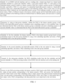
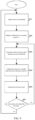
- FIG. 1 is a flowchart of a performance isolation method for a send queue of an RDMA network interface card according to the present disclosure. The method includes the following steps.
- Step S 110 Identify, by an RDMA network interface card on a sending side, a tenant type based on a tenant type identifier included in a queue pair identifier, buffer a work queue element WQE of a send queue of an identified latency-sensitive tenant as a latency-sensitive WQE into a latency-sensitive group of a buffering module, and buffer a WQE of a send queue of an identified bandwidth-sensitive tenant as a bandwidth-sensitive WQE into a bandwidth-sensitive group of the buffering module, where at least some of to-be-processed WQEs buffered into the bandwidth-sensitive group of the buffering module are stored into a wait station, WQEs of different tenants in the latency-sensitive group and the bandwidth-sensitive group that are included in the buffering module are buffered based on different queues, and each node of a queue is a WQE.
- an application that is to be run on an RDMA network interface card (or an application that is to be executed on the RDMA network interface card) is used as a tenant (Tenant) of the RDMA network interface card.
- a queue pair (QP) needs to be created by using a driver, and accordingly, a queue pair (a send queue and a receive queue) resource is applied for.
- the tenant before each tenant that arrives at the RDMA network interface card for the first time creates a queue pair resource for storing a WQE on the RDMA network interface card, the tenant first applies for a tenant identifier (Tenant ID, or referred to as a tenant identification) through a driver interface (such as a request_tenant driver interface) on the RDMA network interface card, and an RDMA network interface card driver registered with a computer operating system allocates the tenant identifier to the tenant that arrives at the RDMA network interface card for the first time.
- a tenant identifier such as a request_tenant driver interface
- the tenant identifier includes a tenant type identifier, a queue pair resource used to store a WQE is created for each tenant that is allocated with a tenant identifier, and the tenants are classified into a latency-sensitive tenant and a bandwidth-sensitive tenant based on tenant type identifiers.
- a process of allocating a tenant type identifier is: receiving, by a first driver interface located on the RDMA network interface card, a request of a tenant for applying for a tenant type identifier, allocating, by a control module on the RDMA network interface card, the tenant type identifier to the tenant, and storing all tenants and tenant type identifiers corresponding to all the tenants.
- Step S120 Determine, by using an inter-group scheduler, whether the WQE in the latency-sensitive group or the WQE in the bandwidth-sensitive group is scheduled, sending a scheduling request to a first scheduler when it is determined that the WQE in the latency-sensitive group is scheduled, and send a scheduling request to a second scheduler when it is determined that the WQE in the bandwidth-sensitive group is scheduled.
- the inter-group scheduler uses an inter-group weighted round robin scheduling algorithm or an inter-group fair round robin scheduling algorithm.
- Step S130 Schedule, by the first scheduler, the latency-sensitive WQE in the latency-sensitive group based on the scheduling request of the inter-group scheduler by using a first scheduling algorithm, and return a WQE scheduling result to the inter-group scheduler.
- the first scheduling algorithm is the fair round robin scheduling algorithm.
- Step S140 Schedule, by the second scheduler, the bandwidth-sensitive WQE in the wait station by using a second scheduling algorithm, and return a WQE scheduling result to the inter-group scheduler.
- the second scheduling algorithm is a token bucket scheduling algorithm.
- Step S150 Transmit, by the inter-group scheduler, the WQE scheduling results from the first scheduler and the second scheduler to a WQE processing module on the RDMA network interface card on the sending side, where a preset quantity of data packets may be one or more, to interrupt a sending task of a bandwidth-sensitive tenant after a length of data is sent, thereby preventing a task from occupying a bandwidth resource on a sending side of the RDMA network interface card for a long time.
- a path maximum transmission unit (Maximum Transmission Unit, MTU) is a maximum data packet size that can be transmitted by a network in bytes, and is a parameter determined by a network device and a communication environment.
- Step S160 Process, by the WQE processing module, the latency-sensitive WQE based on the WQE scheduling result to output all data packets corresponding to the latency-sensitive WQE, and processing the bandwidth-sensitive WQE based on the WQE scheduling result to output, based on the path maximum transmission unit, one data packet corresponding to the bandwidth-sensitive WQE, and if there is a data packet that is not output, write a WQE corresponding to the data packet that is not output back to the wait station.
- the method further includes: receiving, through the first driver interface on the RDMA network interface card, an identification request of a tenant that arrives at the RDMA network interface card for the first time, and providing a tenant identifier to the tenant based on the identification request, where the tenant identifier includes a tenant identifier that includes a tenant type identifier; and creating a queue pair having the queue pair identifier for each tenant allocated with a tenant identifier, and allocating the queue pair resource for storing a WQE to the queue pair, where the queue pair identifier includes the tenant type identifier.
- a method for classifying and marking a queue pair of the RDMA network interface card is used to distinguish between a queue pair used by the latency-sensitive application and a queue pair used by the bandwidth-sensitive application, to further differentially schedule send queues of different service types.
- an application that is to be run on the RDMA network interface card is used as a tenant (Tenant) of the RDMA network interface card.
- an application on the RDMA network interface card may actively apply for a tenant type identifier (Tenant ID) by invoking a request_tenant driver interface provided in the present disclosure.
- the Tenant ID is a value of M digits, that is, a Tenant value range is 0 to 2m.
- the last digit of the Tenant ID can be used to identify a type of a tenant. Specifically, the last digit of the Tenant ID is 0 to identify the latency-sensitive tenant, and the last digit of the Tenant ID is 1 to identify the bandwidth-sensitive tenant.
- a Tenant ID provided by an application is used as a part of a QP identifier (QP ID), as shown in FIG. 3 .
- FIG. 3 is a schematic diagram of an encapsulation relationship between a tenant type identifier and a queue pair identifier according to an embodiment of the present disclosure.
- the tenant type identifier (Tenant ID) is encapsulated as a part of the queue pair identifier (QP ID).
- QP ID queue pair identifier
- a tenant type may be identified as a bandwidth-sensitive type or a latency-sensitive type based on the tenant type identifier encapsulated in the queue pair identifier.
- a tenant (that is, an application) number is further encapsulated in the queue pair identifier. Based on this, a specific application from which a WQE corresponding to the queue pair identifier comes can be identified, and whether the WQE comes from a bandwidth-sensitive application or a latency-sensitive application can also be learned.
- the step of determining, by using an inter-group scheduler, whether the WQE in the latency-sensitive group or the WQE in the bandwidth-sensitive group is scheduled includes: determining, by the inter-group scheduler based on dynamic weights configured for the latency-sensitive group and the bandwidth-sensitive group, whether to schedule the WQE in the latency-sensitive group or the WQE in the bandwidth-sensitive group by using a weighted round robin scheduling algorithm, and updating the dynamic weights based on each scheduling result.
- the updating the dynamic weights based on each scheduling result includes: reducing, based on each scheduling result, a weight of the latency-sensitive group or the bandwidth-sensitive group corresponding to the scheduling result.
- the dynamic weight of the WQE from the latency-sensitive group is positively correlated with a quantity of to-be-processed WQEs from a latency-sensitive tenant in a WQE buffering module
- the dynamic weight of the WQE from the bandwidth-sensitive group is positively correlated with a quantity of to-be-processed WQEs from a bandwidth-sensitive tenant in the WQE buffering module
- the dynamic weights of the WQEs from the latency-sensitive group and the bandwidth-sensitive group are initialized to equal values after being updated to 0 each time
- the dynamic weight of the WQE from the latency-sensitive group is updated after each scheduling performed by using a fair round robin scheduler
- the dynamic weight of the WQE from the bandwidth-sensitive group is updated after each scheduling performed by using a token bucket scheduler.
- step S130 the step of scheduling, by the first scheduler, the latency-sensitive WQE in the latency-sensitive group based on the scheduling request of the inter-group scheduler by using a first scheduling algorithm, and returning a WQE scheduling result to the inter-group scheduler includes: receiving, by the first scheduler, the scheduling request of the inter-group scheduler, and traversing, based on the fair round robin scheduling algorithm, a queue of latency-sensitive WQEs of different tenants in an active linked list maintained by the first scheduler, to poll a queue of latency-sensitive WQEs of the different tenants in the latency-sensitive group, where the active linked list records a queue number of to-be-processed latency-sensitive WQEs of the different tenants in the latency-sensitive group, and one node of the active inked list corresponds to one non-empty queue of latency-sensitive WQEs; and returning a WQE of a queue in a header of the active linked list as the WQE scheduling result to the inter
- the second scheduling algorithm is a token bucket scheduling algorithm
- the step of scheduling, by the second scheduler, the bandwidth-sensitive WQE in the bandwidth-sensitive group of the wait station by using a second scheduling algorithm, and returning a WQE scheduling result to the inter-group scheduler includes: receiving, by the second scheduler, the scheduling request of the inter-group scheduler, and traversing, based on the token bucket scheduling algorithm, a token counter of a queue of bandwidth-sensitive WQEs of different tenants in an active linked list maintained by the second scheduler, to refresh a token and update a token counter count based on a predetermined refresh cycle and each token refresh quantity, where the active linked list records a queue number of to-be-processed bandwidth-sensitive WQEs of the different tenants in the bandwidth-sensitive group, and a node of the active inked list corresponds to a non-empty queue of bandwidth-sensitive WQEs.
- a counting update rule of the token counter is as follows: In a process in which a clock interrupt triggers sequential traversal of token counters in the active linked list, after each traversal, a token counter of a corresponding bandwidth-sensitive tenant is adjusted to a smaller value between a preset maximum value of the token counter and a sum of an original token counter and a quantity of refreshed tokens.
- the method further includes: for the WQEs in the bandwidth-sensitive group in the wait station, maintaining states of all WQEs in the wait station by using a wait WQE state module, externally outputting all wait WQE states, and performing programming control on the WQE states based on set and reset interfaces provided by the wait WQE state module, where the wait WQE states include two states: an idle state and an occupied state.
- Set is a manner of externally forcing an input to be changed, to map the input to an output; and reset is to change an input value to an initial state during power-on by using a program.
- a PLC namely, a programmable logic controller, which uses a type of programmable memory for internal storage of programs, executes user-oriented instructions such as instructions for logic operations, sequential control, timing, counting, and arithmetic operations, and controls various types of mechanical or production processes through digital or analog input/output.
- the purpose of this design is to implement a more logically clear and stepwise explicit organization in PLC programming by using instructions of set and reset operations.
- FIG. 4 shows a structure of a sending side of an RDMA network interface card that supports implementing performance isolation of send queue WQEs of a latency-sensitive application and a bandwidth-sensitive application.
- a WQE buffering module is configured to buffer WQEs of different tenants, thereby masking a reading latency of PCIe interface-based RDMA.
- WQEs of a latency-sensitive tenant and a bandwidth-sensitive tenant are group-buffered, and are divided into a latency-sensitive group and a bandwidth-sensitive group.
- WQEs of different tenants are also stored separately.
- a fair round-robin scheduler is used for the WQEs of different tenants of the latency-sensitive group.
- a wait station is configured to store the WQEs of different tenants of the bandwidth-sensitive group.
- a token bucket scheduler is used for the WQEs in the wait station.
- An inter-group weighted round robin scheduler is used between the latency-sensitive group and the bandwidth-sensitive group.
- a WQE processing module implements processing of WQEs. Fragmentation scheduling is used in a processing process, and an unprocessed WQE is written to the wait station for subsequent scheduling.
- FIG. 4 is a schematic diagram of a structure of a sending side of an RDMA network interface card that supports performance isolation between a latency-sensitive application and a bandwidth-sensitive application according to an embodiment of the present disclosure.
- a buffering module 01 stores a WQE from a bandwidth-sensitive tenant by using a bandwidth-sensitive group 012, stores a WQE from a latency-sensitive tenant by using a latency-sensitive group 011, and stores WQEs from different tenants by using queue classification within the bandwidth-sensitive group 012 and the latency-sensitive group 011.
- the WQE in the latency-sensitive group 011 is scheduled by using a first scheduler 02, the WQE in the bandwidth-sensitive group is first scheduled to a wait station 03 and then is scheduled by using a second scheduler 04, and the WQEs from the latency-sensitive group 011 and the bandwidth-sensitive group 012 are scheduled to a WQE processing module 06 by using an inter-group scheduler 05.
- the WQE processing module 06 completes processing of a scheduled WQE from the latency-sensitive group 011 at one time. However, if the processing of the WQE in the bandwidth-sensitive group 012 cannot be completed in a limited length, the WQE is written back to the wait station 03 to wait for scheduling and processing again.
- FIG. 5 is a schematic diagram of a structure of a sending side of an RDMA network interface card that supports performance isolation between a latency-sensitive application and a bandwidth-sensitive application according to a specific embodiment of the present disclosure.
- a buffering module 01 stores a WQE from a bandwidth-sensitive tenant by using a bandwidth-sensitive group 012, stores a WQE from a latency-sensitive tenant by using a latency-sensitive group 011, and stores WQEs from different tenants by using queue classification within the bandwidth-sensitive group 012 and the latency-sensitive group 011.
- the WQE in the latency-sensitive group 011 is scheduled (based on a fair round robin algorithm) by using a fair round robin scheduler 021, the WQE in the bandwidth-sensitive group is first scheduled to a wait station 03 and then is scheduled (based on a token bucket scheduling algorithm) by using a token bucket scheduler 041, and the WQEs from the latency-sensitive group 011 and the bandwidth-sensitive group 012 are scheduled to a WQE processing module 06 by using an inter-group weighted round robin scheduler 051.
- the WQE processing module 06 completes processing of a scheduled WQE from the latency-sensitive group 011 at one time. However, if the processing of the WQE in the bandwidth-sensitive group 012 cannot be completed in a limited length, the WQE is written back to the wait station 03 to wait for scheduling and processing again.
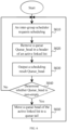
- FIG. 6 is a flowchart of fair round robin scheduling processing in a latency-sensitive group according to an embodiment of the present disclosure.
- a step of polling all queues in the latency-sensitive group by using a fair round robin scheduler includes: polling a queue head of a queue in the latency-sensitive group by periodically traversing an active linked list maintained by the fair round robin scheduler, where each node of the active linked list corresponds to one queue in the latency-sensitive group; and maintaining the active linked list by inserting a node of a queue with a to-be-processed WQE into the active linked list and deleting a node corresponding to a queue without a to-be-processed WQE from the active linked list.
- a WQE of the latency-sensitive group is scheduled by using a fair round robin scheduling algorithm, to ensure that each WQE of the latency-sensitive tenant has an equal opportunity of being processed by a WQE processing module.
- an active linked list needs to be maintained. Elements in the active linked list (the linked list may be a single linked list, a doubly linked list, or a circular linked list) are numbers of WQE queues of different tenants in the latency-sensitive group, and the active linked list includes only an active queue number of a queue with a to-be-processed element.
- FIG. 6 describes an execution procedure of the fair round robin scheduling algorithm used in the present disclosure, including the following steps.
- Step S610 An inter-group scheduler requests scheduling.
- Step S620 Remove a queue Queue_head in a header of the active linked list, where Queue_head is a scheduling result of this fair polling.
- Step S630 Output the scheduling result Queue_head to a WQE processing module.
- Step S640 After the scheduling result is output, determine whether Queue_head is empty, and if Queue_head is not empty, return to step S610.
- Step S650 If Queue_head is empty, move a queue head of the active linked list to a queue tail, and return to step S610.
- a bandwidth-sensitive WQE slicing (and writing back) processing method is used, to avoid a bandwidth-sensitive WQE occupying the WQE processing module for a long time.
- the WQE slicing processing method provided in the present disclosure relates to two key elements, a wait station for storing a WQE in an executable state and a WQE processing module that supports WQE slicing.
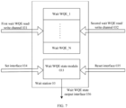
- FIG. 7 is a schematic diagram of a structure of a wait station according to an embodiment of the present disclosure.
- the wait station uses a true dual-port SRAM (including a first wait WQE read/write channel 031 and a second wait WQE read/write channel 032) to implement storage of wait WQEs, and the two read/write channels (including the first wait WQE read/write channel 031 and a second wait WQE read/write channel 032) implement read/write of WQEs in bandwidth-sensitive groups in wait stations 03 at different positions, where the first wait WQE read/write channel 031 is configured to store a WQE from a buffering module to the wait station, and the second wait WQE read/write channel 032 is configured to return a WQE that is not completely processed by a processing module to the wait station.
- a true dual-port SRAM including a first wait WQE read/write channel 031 and a second wait WQE read/write channel 032 to implement storage of wait WQEs
- a wait WQE state module 033 maintains states of all the wait WQEs through a set interface 034 and a reset interface 035.
- the wait WQE states include two states: an idle state and an occupied state.
- the wait WQE state module further provides a wait WQE state output interface 036 for externally outputting all wait WQE states.
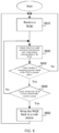
- FIG. 8 is a flowchart of implementing WQE slicing by a WQE processing module according to an embodiment of the present disclosure.
- slicing processing may be performed on only a task corresponding to a WQE of a bandwidth-sensitive tenant.
- the flowchart includes the following steps.
- Step S810 The WQE processing module receives a to-be-processed WQE.
- Step S820 The WQE processing module outputs, based on a path maximum transmission unit (PMTU), a data packet corresponding to the WQE.
- PMTU path maximum transmission unit
- Step S830 After the data packet is output, check whether a remaining message length of the WQE is greater than 0, and if the remaining message length of the WQE is not greater than 0, return to step S810, and continue to prepare to receive a next to-be-processed WQE.
- Step S840 If the remaining message length of the WQE is greater than 0, continue to check whether the WQE is from a bandwidth-sensitive group, and if the WQE is not from the bandwidth-sensitive group, return to step S820.
- Step S850 If it is detected that the WQE is from the bandwidth-sensitive group, write an unprocessed WQE back to a wait station, and return to step S810.
- FIG. 9 is a flowchart of maintaining a token counter according to an embodiment of the present disclosure. Specifically, an update rule of the token counter is shown, including the following steps.
- Step S910 Trigger with a clock interrupt (to sequentially traverse a token counter of an active linked list).
- Step S920 Initialize a linked list access pointer rd_ptr to 1.
- Step S930 Read token_bucket of the (rd_ptr) th element in the active linked list.
- Step S950 Progressively increase rd_ptr.
- Step S960 Check whether the entire active linked list is traversed, if the entire active linked list is traversed, return to step S910, or if the entire active linked list is not traversed, return to step S930.
- FIG. 10 is a procedure of executing bandwidth-sensitive WQE scheduling based on a token bucket algorithm according to an embodiment of the present disclosure, including the following steps.
- Step S1010 An inter-group scheduler requests scheduling.
- Step S1020 Remove a queue Queue_head in a header of the active linked list.
- Step S1030 Determine whether a token counter token_bucket corresponding to Queue_head is greater than a path maximum transmission unit (PMTU).
- PMTU path maximum transmission unit
- Step S1040 If the token counter token_bucket corresponding to Queue_head is greater than the path maximum transmission unit (PMTU), schedule a WQE corresponding to Queue_head.
- PMTU path maximum transmission unit
- Step S1050 If the token counter token_bucket corresponding to the Queue_head is not greater than the path maximum transmission unit (PMTU), insert Queue_head into the tail of the linked list and return to step S1020.
- PMTU path maximum transmission unit
- Step S1060 Subtract the PMTU from token_bucket.
- Step S1070 Insert Queue_head into the tail of the linked list and return to step S1010.
- the token bucket scheduling algorithm is used to schedule the bandwidth-sensitive WQE in the wait station, to achieve a performance isolation effect that active bandwidth-sensitive tenants fairly share an available bandwidth.
- a token counter token_bucket is maintained for each bandwidth-sensitive tenant, and a maximum value of the counter is B.
- a timer is maintained, and a refresh cycle of the timer is T.
- a quantity of tenants in an active bandwidth-sensitive group is NA
- all bandwidth-sensitive tenants may obtain a bandwidth of BW
- each active bandwidth-sensitive tenant shall obtain a bandwidth of BW/NA.
- it is specified that a quantity of refreshed tokens in the token bucket algorithm is F.
- BW/NA should be approximately equal to F/T.
- an active linked list needs to be maintained. Elements in the active linked list are queue numbers of wait WQEs of different tenants in the bandwidth-sensitive group, and the active linked list includes only an active queue number when the WQEs are in a to-be-processed state.
- Q_j is written to the wait station
- Q_j is inserted into the active linked list.
- Q_k is deleted from the active linked list.
- FIG. 11 is a weighted round robin scheduling process according to an embodiment of the present disclosure.
- a weighted round robin manner is used to schedule the WQEs of the latency-sensitive group and the bandwidth-sensitive group, and two groups of weights are configurable, thereby improving flexibility of differentiated services.
- two groups of dynamic weights need to be maintained, for ls_cnt of the latency-sensitive group and bs_cnt for of the bandwidth-sensitive group.
- the weighted round robin scheduling process includes the following steps.
- Step S1110 A WQE processing module requests scheduling.
- Step S1 120 Determine whether ls_cnt is greater than or equal to bs_cnt, and if ls_cnt is greater than or equal to bs_cnt, perform step S1130 and step S1140 successively, or if ls_cnt is not greater than or equal to bs_cnt, perform step S1150 and step S1160 successively.
- Step S1130 Schedule the latency-sensitivity group.
- Step S1140 Progressively decrease ls_cnt, and perform step S1170.
- Step S1150 Schedule the bandwidth-sensitive group.
- Step S1160 Progressively decrease bs_cnt, and perform step S1170.
- Step S1170 Determine whether ls_cnt and bs_cnt are both equal to 0, and if ls_cnt and bs_cnt are not both equal to 0, return step S1110, or if ls_cnt and bs_cnt are both equal to 0, perform step S1180.
- Step S1180 Re-initialize ls_cnt and bs_cnt to w_ls and w_bs.
- the physical address of each network interface card is unique in the world and is stored in a PROM of the network interface card.
- the physical address of one of the network interface cards is read from the PROM, and content of the physical address is written into a physical address register and a data structure variable of the other network interface card.
- the two network interface cards have completely same physical addresses. Based on this design, the present disclosure can implement switching between two network interface cards.
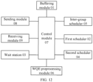
- FIG. 12 is a schematic diagram of a structure of an RDMA network interface card according to an embodiment of the present disclosure.
- the RDMA network interface card includes a buffering module 01, a first scheduler 02, a wait station 03, a second scheduler 04, an inter-group scheduler 05, a WQE processing module 06, a control module 07, a sending module 08, and a receiving module 09.
- the control module 07 is configured to identify a tenant type based on a tenant type identifier included in a queue pair identifier, buffer a work queue element WQE of a send queue of an identified latency-sensitive tenant as a latency-sensitive WQE into a latency-sensitive group of the buffering module 01, and buffer a WQE of a send queue of an identified bandwidth-sensitive tenant as a bandwidth-sensitive WQE into a bandwidth-sensitive group of the buffering module 01, where at least some of to-be-processed WQEs buffered into the bandwidth-sensitive group of the buffering module 01 are stored into the wait station 03, WQEs of different tenants in the latency-sensitive group and the bandwidth-sensitive group that are included in the buffering module are buffered based on different queues, and each node of a queue is a WQE.
- the wait station 03 is configured to record at least some of to-be-processed WQEs in the bandwidth-sensitive group.
- the structure includes a true dual-port SRAM, a wait WQE state module 033, a set interface 034, and a reset interface 035.
- the true dual-port SRAM includes a first wait WQE read/write channel 031 and a second wait WQE read/write channel 032.
- the first wait WQE read/write channel 031 is configured to transmit the bandwidth-sensitive WQE in the bandwidth-sensitive group in the buffering module to the wait station
- the second wait WQE read/write channel 032 is configured to write a WQE corresponding to a data packet that is not output back to the wait station.
- the wait WQE state module 033 is configured to maintain states of all WQEs in the wait station and externally output all wait WQE states.
- the set interface 034 and the reset interface 035 are configured to perform programming control on the WQE states, where the wait WQE states include two states: an idle state and an occupied state.
- the inter-group scheduler 05 is configured to determine whether the WQE in the latency-sensitive group or the WQE in the bandwidth-sensitive group is scheduled, send a scheduling request to a first scheduler when it is determined that the WQE in the latency-sensitive group is scheduled, send a scheduling request to a second scheduler when it is determined that the WQE in the bandwidth-sensitive group is scheduled, and transmit WQE scheduling results from the first scheduler 02 and the second scheduler 04 to the WQE processing module.
- the first scheduler 05 is configured to schedule the latency-sensitive WQE in the latency-sensitive group based on the scheduling request of the inter-group scheduler by using a first scheduling algorithm, and return a WQE scheduling result to the inter-group scheduler 05.
- the second scheduler 04 is configured to schedule the bandwidth-sensitive WQE in the bandwidth-sensitive group in the wait station 03 by using a second scheduling algorithm, and return a WQE scheduling result to the inter-group scheduler 05.
- the WQE processing module 06 is configured to process the latency-sensitive WQE based on the WQE scheduling result to output all data packets corresponding to the latency-sensitive WQE, and process the bandwidth-sensitive WQE based on the WQE scheduling result to output, based on a path maximum transmission unit, one data packet corresponding to the bandwidth-sensitive WQE, and if there is a data packet that is not output, write a WQE corresponding to the data packet that is not output back to the wait station.
- the control module 07 is configured to identify a tenant type based on a tenant type identifier included in a queue pair identifier, buffer a work queue element WQE of a send queue of an identified latency-sensitive tenant as a latency-sensitive WQE into a latency-sensitive group of the buffering module, and buffer a WQE of a send queue of an identified bandwidth-sensitive tenant as a bandwidth-sensitive WQE into a bandwidth-sensitive group of the buffering module, where at least some of to-be-processed WQEs buffered into the bandwidth-sensitive group of the buffering module are stored into the wait station, WQEs of different tenants in the latency-sensitive group and the bandwidth-sensitive group that are included in the buffering module are buffered based on different queues, and each node of a queue is a WQE.
- the sending module 08 is a conventional configuration of the RDMA network interface card, and is configured to send data corresponding to a WQE.
- the receiving module 09 is a conventional configuration of the RDMA network interface card, and is configured to receive data from another network interface card.
- the present disclosure further provides a performance isolation system for a send queue of an RDMA network interface card.
- the system includes a computer device, the computer device includes a processor and a memory, the memory stores computer instructions, the processor is configured to execute the computer instructions stored in the memory, and when the computer instructions are executed by the processor, the system implements the steps of the foregoing method.
- An embodiment of the present disclosure further provides a computer-readable storage medium, on which a computer program is stored.
- the computer program is executed by a processor to implement the steps of the foregoing method.
- the computer-readable storage medium may be a tangible storage medium, such as a random access memory (RAM), a memory, a read-only memory (ROM), an electrically programmable ROM, an electrically erasable programmable ROM, a register, a floppy disk, a hard disk, a removable storage disk, a CD-ROM, or any other form of storage medium known in the art.
- the performance isolation method and system for a send queue of an RDMA network interface card, and the storage medium that are provided in the present disclosure have the following advantages:
- the exemplary components, systems, and methods described with reference to the embodiments disclosed herein may be implemented with hardware, software, or a combination of hardware and software. Specifically, whether the exemplary components, systems, and methods are implemented with hardware or software depends on particular application and design constraints of the technical solution. Persons skilled in the art may implement the described functions using different methods for each particular application, but such implementation should not be considered beyond the scope of the present disclosure.
- the hardware may be, for example, an electronic circuit, an application-specific integrated circuit (ASIC), appropriate firmware, a plug-in, a function card, or the like.
- ASIC application-specific integrated circuit
- an element in the present disclosure is a program or a code segment that is used to execute a required task.
- the program or the code segment may be stored in a machine-readable medium, or transmitted on a transmission medium or a communication link by using a data signal carried in a carrier.
- features described and/or exemplified in one implementation may be used in one or more other implementations in a same manner or in a similar manner, and/or may be combined with or replace features of other implementations.
Landscapes
- Engineering & Computer Science (AREA)
- Computer Networks & Wireless Communication (AREA)
- Signal Processing (AREA)
- Theoretical Computer Science (AREA)
- Software Systems (AREA)
- Physics & Mathematics (AREA)
- General Engineering & Computer Science (AREA)
- General Physics & Mathematics (AREA)
- Computer Hardware Design (AREA)
- Mathematical Physics (AREA)
- Data Exchanges In Wide-Area Networks (AREA)
- Multi Processors (AREA)
Applications Claiming Priority (1)
| Application Number | Priority Date | Filing Date | Title |
|---|---|---|---|
| CN202310762123.8A CN116800684B (zh) | 2023-06-27 | 2023-06-27 | Rdma网卡发送队列的性能隔离方法和rdma网卡 |
Publications (1)
| Publication Number | Publication Date |
|---|---|
| EP4485196A1 true EP4485196A1 (de) | 2025-01-01 |
Family
ID=88036006
Family Applications (1)
| Application Number | Title | Priority Date | Filing Date |
|---|---|---|---|
| EP24171558.0A Pending EP4485196A1 (de) | 2023-06-27 | 2024-04-22 | Leistungsisolierungsverfahren für sendewarteschlange einer rdma-netzwerkschnittstellenkarte und rdma-netzwerkschnittstellenkarte |
Country Status (4)
| Country | Link |
|---|---|
| US (1) | US12706865B2 (de) |
| EP (1) | EP4485196A1 (de) |
| JP (1) | JP7690641B2 (de) |
| CN (1) | CN116800684B (de) |
Cited By (1)
| Publication number | Priority date | Publication date | Assignee | Title |
|---|---|---|---|---|
| CN119854373A (zh) * | 2025-03-20 | 2025-04-18 | 中国人民解放军国防科技大学 | 一种基于rdma的数据传输系统及方法 |
Families Citing this family (7)
| Publication number | Priority date | Publication date | Assignee | Title |
|---|---|---|---|---|
| CN118413492B (zh) * | 2024-04-29 | 2025-09-05 | 天翼云科技有限公司 | 一种端到端双通道存储io处理方法 |
| CN119271618B (zh) * | 2024-10-18 | 2025-12-02 | 无锡众星微系统技术有限公司 | 一种rdma网卡请求队列的实现方法及系统 |
| CN119835239B (zh) * | 2024-12-31 | 2026-05-05 | 无锡众星微系统技术有限公司 | 一种基于rdma的单qp场景性能优化系统及方法 |
| CN119788571B (zh) * | 2025-01-06 | 2025-09-30 | 南京邮电大学 | 一种基于环回测试的主机内部网络延迟诊断方法 |
| CN120474926B (zh) * | 2025-06-06 | 2025-11-04 | 北京翼华云网科技有限公司 | 一种基于Soft-RoCE的虚拟网络拓扑模拟方法 |
| CN121098817B (zh) * | 2025-11-11 | 2026-02-27 | 中国铁塔股份有限公司江苏省分公司 | 面向NVMe-oF存储的细粒度QoS隔离方法及装置 |
| CN121578869B (zh) * | 2026-01-26 | 2026-03-27 | 深圳云豹智能股份有限公司 | Rdma网卡的复位注销方法、rdma网卡、系统、芯片、存储介质及程序产品 |
Family Cites Families (9)
| Publication number | Priority date | Publication date | Assignee | Title |
|---|---|---|---|---|
| US8458280B2 (en) * | 2005-04-08 | 2013-06-04 | Intel-Ne, Inc. | Apparatus and method for packet transmission over a high speed network supporting remote direct memory access operations |
| CN101834787A (zh) * | 2010-04-12 | 2010-09-15 | 中兴通讯股份有限公司 | 调度数据的方法和系统 |
| US10305772B2 (en) * | 2015-03-30 | 2019-05-28 | Mellanox Technologies, Ltd. | Using a single work item to send multiple messages |
| US10048876B2 (en) * | 2015-09-10 | 2018-08-14 | Western Digital Technologies, Inc. | Method for providing nonvolatile storage write bandwidth using a caching namespace |
| CN109905329B (zh) * | 2019-01-04 | 2021-06-08 | 东南大学 | 一种虚拟化环境下任务类型感知的流队列自适应管理方法 |
| US11409685B1 (en) * | 2020-09-24 | 2022-08-09 | Amazon Technologies, Inc. | Data synchronization operation at distributed computing system |
| EP4276638A4 (de) * | 2021-02-09 | 2024-02-21 | Huawei Technologies Co., Ltd. | System und verfahren zum zugriff auf entfernte ressourcen |
| CN114124830B (zh) * | 2021-11-19 | 2024-04-30 | 南京大学 | 一种面向数据中心多应用场景的rdma服务质量保证方法及系统 |
| CN114666281A (zh) | 2022-03-18 | 2022-06-24 | 南京大学 | 基于智能网卡卸载的数据中心多应用QoS保障系统及方法 |
-
2023
- 2023-06-27 CN CN202310762123.8A patent/CN116800684B/zh active Active
-
2024
- 2024-04-22 EP EP24171558.0A patent/EP4485196A1/de active Pending
- 2024-04-24 JP JP2024070295A patent/JP7690641B2/ja active Active
- 2024-04-28 US US18/648,380 patent/US12706865B2/en active Active
Non-Patent Citations (2)
| Title |
|---|
| LIAO YUNKUN ET AL: "Optimize the TX Architecture of RDMA NIC for Performance Isolation in the Cloud Environment", PROCEEDINGS OF THE GREAT LAKES SYMPOSIUM ON VLSI 2023, ACMPUB27, NEW YORK, NY, USA, 5 June 2023 (2023-06-05), pages 29 - 35, XP059399409, ISBN: 979-8-4007-0125-2, DOI: 10.1145/3583781.3590276 * |
| YIWEN ZHANG? ET AL: "Justitia: Software Multi-Tenancy in Hardware Kernel-Bypass Networks", 4 April 2022 (2022-04-04), pages 1 - 20, XP061071340, Retrieved from the Internet <URL:http://www.usenix.org/system/files/nsdi22spring_prepub_zhang-yiwen.pdf> [retrieved on 20220404] * |
Cited By (1)
| Publication number | Priority date | Publication date | Assignee | Title |
|---|---|---|---|---|
| CN119854373A (zh) * | 2025-03-20 | 2025-04-18 | 中国人民解放军国防科技大学 | 一种基于rdma的数据传输系统及方法 |
Also Published As
| Publication number | Publication date |
|---|---|
| US12706865B2 (en) | 2026-08-11 |
| JP2025005382A (ja) | 2025-01-16 |
| CN116800684A (zh) | 2023-09-22 |
| CN116800684B (zh) | 2024-06-07 |
| JP7690641B2 (ja) | 2025-06-10 |
| US20250007862A1 (en) | 2025-01-02 |
Similar Documents
| Publication | Publication Date | Title |
|---|---|---|
| US20250007862A1 (en) | Performance isolation method for send queue of rdma network interface card and rdma network interface card | |
| US11799764B2 (en) | System and method for facilitating efficient packet injection into an output buffer in a network interface controller (NIC) | |
| US11082366B2 (en) | Method and apparatus for using multiple linked memory lists | |
| US7292593B1 (en) | Arrangement in a channel adapter for segregating transmit packet data in transmit buffers based on respective virtual lanes | |
| EP1421739B1 (de) | Übertragung von Datenpaketen an mehrere Zieladressen | |
| US7603429B2 (en) | Network adapter with shared database for message context information | |
| US7209489B1 (en) | Arrangement in a channel adapter for servicing work notifications based on link layer virtual lane processing | |
| CN115695578A (zh) | 一种数据中心网络tcp和rdma混合流调度方法、系统及装置 | |
| US12452189B2 (en) | Context-aware NVMe processing in virtualized environments | |
| CN111970213B (zh) | 一种将数据写入存储器的方法及网元 | |
| CN114116184B (zh) | 虚拟场景中的数据处理方法及装置、设备、介质 | |
| US12363204B1 (en) | High performance connection scheduler | |
| US10623521B2 (en) | Distribution of messages to queues in a distributed computing environment | |
| CN114500403A (zh) | 一种数据处理方法、装置及计算机可读存储介质 | |
| US7583678B1 (en) | Methods and apparatus for scheduling entities using a primary scheduling mechanism such as calendar scheduling filled in with entities from a secondary scheduling mechanism | |
| JP2014179838A (ja) | 通信装置、およびプログラム | |
| CN118972354B (zh) | 电信网元实时处理方法、装置、设备、介质及程序产品 | |
| JP7765055B1 (ja) | ネットワークインターフェース装置、パケット転送方法、およびプログラム | |
| HK40118223A (en) | Fragmented message tuple recovery method, network card, gateway, storage medium and program | |
| HK40118223B (en) | Fragmented message tuple recovery method, network card, gateway, storage medium and program | |
| WO2025248312A1 (zh) | 数据包转发方法、网关设备、存储介质和程序 | |
| CN113626216A (zh) | 优化基于远程直接数据存取的网络应用性能的方法及系统 | |
| HK40025316A (en) | Bandwidth isolation device and method | |
| HK1227576A1 (en) | Method and apparatus for using multiple linked memory lists |
Legal Events
| Date | Code | Title | Description |
|---|---|---|---|
| PUAI | Public reference made under article 153(3) epc to a published international application that has entered the european phase |
Free format text: ORIGINAL CODE: 0009012 |
|
| STAA | Information on the status of an ep patent application or granted ep patent |
Free format text: STATUS: REQUEST FOR EXAMINATION WAS MADE |
|
| 17P | Request for examination filed |
Effective date: 20240422 |
|
| AK | Designated contracting states |
Kind code of ref document: A1 Designated state(s): AL AT BE BG CH CY CZ DE DK EE ES FI FR GB GR HR HU IE IS IT LI LT LU LV MC ME MK MT NL NO PL PT RO RS SE SI SK SM TR |